EP0530045A1 - Modulated bias units for steerable rotary drilling systems - Google Patents
Modulated bias units for steerable rotary drilling systems Download PDFInfo
- Publication number
- EP0530045A1 EP0530045A1 EP92307882A EP92307882A EP0530045A1 EP 0530045 A1 EP0530045 A1 EP 0530045A1 EP 92307882 A EP92307882 A EP 92307882A EP 92307882 A EP92307882 A EP 92307882A EP 0530045 A1 EP0530045 A1 EP 0530045A1
- Authority
- EP
- European Patent Office
- Prior art keywords
- bias unit
- unit according
- body structure
- cavity
- modulated bias
- Prior art date
- Legal status (The legal status is an assumption and is not a legal conclusion. Google has not performed a legal analysis and makes no representation as to the accuracy of the status listed.)
- Granted
Links
- 238000005553 drilling Methods 0.000 title claims abstract description 126
- 239000012530 fluid Substances 0.000 claims abstract description 111
- 230000015572 biosynthetic process Effects 0.000 claims abstract description 28
- 238000005755 formation reaction Methods 0.000 claims abstract description 28
- 238000004891 communication Methods 0.000 claims abstract description 24
- 238000005520 cutting process Methods 0.000 claims description 12
- 230000002093 peripheral effect Effects 0.000 claims description 12
- 230000000694 effects Effects 0.000 claims description 9
- 230000007246 mechanism Effects 0.000 claims description 9
- 229920001971 elastomer Polymers 0.000 claims description 8
- 238000007789 sealing Methods 0.000 claims description 8
- 238000005096 rolling process Methods 0.000 claims description 6
- 238000003475 lamination Methods 0.000 claims description 5
- 229910052751 metal Inorganic materials 0.000 claims description 5
- 239000002184 metal Substances 0.000 claims description 5
- 239000000806 elastomer Substances 0.000 claims description 4
- 230000001050 lubricating effect Effects 0.000 claims description 3
- 230000002706 hydrostatic effect Effects 0.000 description 13
- 238000006073 displacement reaction Methods 0.000 description 11
- 241000239290 Araneae Species 0.000 description 10
- 230000000712 assembly Effects 0.000 description 8
- 238000000429 assembly Methods 0.000 description 8
- 229910003460 diamond Inorganic materials 0.000 description 7
- 239000010432 diamond Substances 0.000 description 7
- 230000000737 periodic effect Effects 0.000 description 7
- 230000002238 attenuated effect Effects 0.000 description 6
- UONOETXJSWQNOL-UHFFFAOYSA-N tungsten carbide Chemical compound [W+]#[C-] UONOETXJSWQNOL-UHFFFAOYSA-N 0.000 description 5
- 238000011144 upstream manufacturing Methods 0.000 description 5
- 238000005299 abrasion Methods 0.000 description 4
- 230000008878 coupling Effects 0.000 description 4
- 238000010168 coupling process Methods 0.000 description 4
- 238000005859 coupling reaction Methods 0.000 description 4
- 230000001360 synchronised effect Effects 0.000 description 4
- 230000006835 compression Effects 0.000 description 3
- 238000007906 compression Methods 0.000 description 3
- 238000010586 diagram Methods 0.000 description 3
- 239000011148 porous material Substances 0.000 description 3
- 238000010276 construction Methods 0.000 description 2
- 238000009434 installation Methods 0.000 description 2
- 239000000463 material Substances 0.000 description 2
- 238000000034 method Methods 0.000 description 2
- 125000006850 spacer group Chemical group 0.000 description 2
- 239000000758 substrate Substances 0.000 description 2
- 241001331845 Equus asinus x caballus Species 0.000 description 1
- XQCFHQBGMWUEMY-ZPUQHVIOSA-N Nitrovin Chemical compound C=1C=C([N+]([O-])=O)OC=1\C=C\C(=NNC(=N)N)\C=C\C1=CC=C([N+]([O-])=O)O1 XQCFHQBGMWUEMY-ZPUQHVIOSA-N 0.000 description 1
- 238000006243 chemical reaction Methods 0.000 description 1
- 238000011109 contamination Methods 0.000 description 1
- 230000001419 dependent effect Effects 0.000 description 1
- 238000005516 engineering process Methods 0.000 description 1
- 230000003628 erosive effect Effects 0.000 description 1
- 239000004744 fabric Substances 0.000 description 1
- 238000007667 floating Methods 0.000 description 1
- 238000011010 flushing procedure Methods 0.000 description 1
- 230000001771 impaired effect Effects 0.000 description 1
- 230000000670 limiting effect Effects 0.000 description 1
- 239000002245 particle Substances 0.000 description 1
- 238000005086 pumping Methods 0.000 description 1
- 230000005855 radiation Effects 0.000 description 1
- 230000002829 reductive effect Effects 0.000 description 1
- 238000009419 refurbishment Methods 0.000 description 1
- 238000009877 rendering Methods 0.000 description 1
- 230000000717 retained effect Effects 0.000 description 1
- 230000035945 sensitivity Effects 0.000 description 1
- 238000000926 separation method Methods 0.000 description 1
- 230000006641 stabilisation Effects 0.000 description 1
- 239000003381 stabilizer Substances 0.000 description 1
- 239000002759 woven fabric Substances 0.000 description 1
Images


Classifications
-
- E—FIXED CONSTRUCTIONS
- E21—EARTH DRILLING; MINING
- E21B—EARTH DRILLING, e.g. DEEP DRILLING; OBTAINING OIL, GAS, WATER, SOLUBLE OR MELTABLE MATERIALS OR A SLURRY OF MINERALS FROM WELLS
- E21B7/00—Special methods or apparatus for drilling
- E21B7/04—Directional drilling
- E21B7/06—Deflecting the direction of boreholes
-
- E—FIXED CONSTRUCTIONS
- E21—EARTH DRILLING; MINING
- E21B—EARTH DRILLING, e.g. DEEP DRILLING; OBTAINING OIL, GAS, WATER, SOLUBLE OR MELTABLE MATERIALS OR A SLURRY OF MINERALS FROM WELLS
- E21B4/00—Drives for drilling, used in the borehole
- E21B4/02—Fluid rotary type drives
-
- E—FIXED CONSTRUCTIONS
- E21—EARTH DRILLING; MINING
- E21B—EARTH DRILLING, e.g. DEEP DRILLING; OBTAINING OIL, GAS, WATER, SOLUBLE OR MELTABLE MATERIALS OR A SLURRY OF MINERALS FROM WELLS
- E21B41/00—Equipment or details not covered by groups E21B15/00 - E21B40/00
- E21B41/0085—Adaptations of electric power generating means for use in boreholes
-
- E—FIXED CONSTRUCTIONS
- E21—EARTH DRILLING; MINING
- E21B—EARTH DRILLING, e.g. DEEP DRILLING; OBTAINING OIL, GAS, WATER, SOLUBLE OR MELTABLE MATERIALS OR A SLURRY OF MINERALS FROM WELLS
- E21B47/00—Survey of boreholes or wells
- E21B47/02—Determining slope or direction
- E21B47/022—Determining slope or direction of the borehole, e.g. using geomagnetism
-
- E—FIXED CONSTRUCTIONS
- E21—EARTH DRILLING; MINING
- E21B—EARTH DRILLING, e.g. DEEP DRILLING; OBTAINING OIL, GAS, WATER, SOLUBLE OR MELTABLE MATERIALS OR A SLURRY OF MINERALS FROM WELLS
- E21B47/00—Survey of boreholes or wells
- E21B47/02—Determining slope or direction
- E21B47/024—Determining slope or direction of devices in the borehole
-
- E—FIXED CONSTRUCTIONS
- E21—EARTH DRILLING; MINING
- E21B—EARTH DRILLING, e.g. DEEP DRILLING; OBTAINING OIL, GAS, WATER, SOLUBLE OR MELTABLE MATERIALS OR A SLURRY OF MINERALS FROM WELLS
- E21B7/00—Special methods or apparatus for drilling
- E21B7/04—Directional drilling
-
- E—FIXED CONSTRUCTIONS
- E21—EARTH DRILLING; MINING
- E21B—EARTH DRILLING, e.g. DEEP DRILLING; OBTAINING OIL, GAS, WATER, SOLUBLE OR MELTABLE MATERIALS OR A SLURRY OF MINERALS FROM WELLS
- E21B7/00—Special methods or apparatus for drilling
- E21B7/04—Directional drilling
- E21B7/06—Deflecting the direction of boreholes
- E21B7/064—Deflecting the direction of boreholes specially adapted drill bits therefor
-
- E—FIXED CONSTRUCTIONS
- E21—EARTH DRILLING; MINING
- E21B—EARTH DRILLING, e.g. DEEP DRILLING; OBTAINING OIL, GAS, WATER, SOLUBLE OR MELTABLE MATERIALS OR A SLURRY OF MINERALS FROM WELLS
- E21B47/00—Survey of boreholes or wells
- E21B47/01—Devices for supporting measuring instruments on drill bits, pipes, rods or wirelines; Protecting measuring instruments in boreholes against heat, shock, pressure or the like
Abstract
Description
- When drilling or coring holes in sub-surface formations, it is sometimes desirable to be able to vary and control the direction of drilling, for example to direct the borehole towards a desired target, or to control the direction horizontally within the payzone once the target has been reached. It may also be desirable to correct for deviations from the desired direction when drilling a straight hole, or to control the direction of the hole to avoid obstacles.
- "Rotary drilling" is defined as a system in which a downhole assembly, including the drill bit, is connected to a drill string which is rotatably driven from the drilling platform. The established methods of directional control during rotary drilling involve variations in bit weight, r.p.m. and stabilisation. However, the directional control which can be exercised by these methods is limited and conflicts with optimising bit performance. Hitherto, therefore, fully controllable directional drilling has normally required the drill bit to be rotated by a downhole motor, either a turbine or PDM (positive displacement motor). The drill bit may then, for example, be coupled to the motor by a double tilt unit whereby the central axis of the drill bit is inclined to the axis of the motor. During normal drilling the effect of this inclination is nullified by continual rotation of the drill string, and hence the motor casing, as the bit is rotated by the motor. When variation of the direction of drilling is required, the rotation of the drill string is stopped with the bit tilted in the required direction. Continued rotation of the drill bit by the motor then causes the bit to drill in that direction.
- The instantaneous rotational orientation of the motor casing is sensed by survey instruments carried adjacent the motor and the required rotational orientation of the motor casing for drilling in the appropriate direction is set by rotational positioning of the drill string, from the drilling platform, in response to the information received in signals from the downhole survey instruments. A similar effect to the use of a double tilt unit may be achieved by the use of a "bent" motor, a "bent" sub-assembly above or below the motor, or an offset stabiliser on the outside of the motor casing. In each case the effect is nullified during normal drilling by continual rotation of the drill string, such rotation being stopped when deviation of the drilling direction is required.
- Although such arrangements allow accurately controlled directional drilling to be achieved, using a downhole motor to drive the drill bit, there are reasons why rotary drilling is to be preferred.
- Thus, rotary drilling is generally less costly than drilling with a downhole motor. Not only are the motor units themselves costly, and require periodic replacement or refurbishment, but the higher torque at lower rotational speeds permitted by rotary drilling provide improved bit performance and hence lower drilling cost per foot.
- Also, in steered motor drilling considerable difficulty may be experienced in accurately positioning the motor in the required rotational orientation, due to stick/slip rotation of the drill string in the borehole as attempts are made to orientate the motor by rotation of the drill string from the surface. Also, rotational orientation of the motor is affected by the wind-up in the drill string, which will vary according to the reactive torque from the motor and the angular compliance of the drill string.
- Accordingly, some attention has been given to arrangements for achieving a fully steerable rotary drilling system.
- For example, Patent Specification No. WEO90/05235 describes a steerable rotary drilling system in which the drill bit is coupled to the lower end of the drill string through a universal joint which allows the bit to pivot relative to the string axis. The bit is contra-nutated in an orbit of fixed radius and at a rate equal to the drill string rotation but in the opposite direction. This speed-controlled and phase-controlled bit nutation keeps the bit heading off-axis in a fixed direction. Such arrangement requires the provision of a controlled servo of high power.
- British Patent Specification No. 2246151 describes an alternative form of steerable rotary drilling system in which an asymmetrical drill bit is coupled to a mud hammer. The direction of the borehole is selected by selecting a particular phase relation between rotation of the drill bit and the periodic operation of the mud hammer.
- British Patent Specifications Nos. 2172324 A, 2172325 A and 2177738 A (Cambridge Radiation Technology Limited) disclose arrangements in which lateral forces are applied to a drilling tube above the drill bit so as to impart a curvature to the drilling tube and thereby control the drilling direction. Such arrangements are complex and require large downhole assemblies.
- U.S. Specification No. 4995465 (J. L. Beck and L. D. Taylor) describes a rotary drilling system in which a bent-sub is connected behind the drill bit so that the bit extends angularly with respect to the drill rod. An actuator, such as an hydraulic ram, is provided at the surface for exerting thrust on the end of the drill rod which is transmitted along the rod to the drill bit. The thrust applied axially along the drill rod is pulsed to effect the desired trajectory of the drilling, the pulsing of the drill rod being based upon signals received from a downhole monitor.
- U.S. Specification No. 4637479 (L. J. Leising) describes a roller-cone bit carried on a drilling tool in which a rotating flow-obstructing member controls the flow of drilling fluid to discharge passages in the drill bit. By controlling the rate of rotation of the flow obstructing member, drilling fluid may be sequentially discharged from the bit passages into only a single peripheral sector of the borehole, thereby diverting the drill bit into a different path by eroding the formation in that sector.
- Our British Patent Application No. 9025465.7 refers to the use of an hydrostatic bearing, for example in the gauge section of a drill bit, to provide low-friction engagement between a bearing pad and the wall of the borehole. Such a low-friction bearing pad is required in certain arrangements for reducing or eliminating bit whirl.
- US Specification No. 4416339 discloses a device for effecting deviation of a drill bit during rotary drilling, the device comprising a hinged paddle which may be urged outwardly from the drill string and toward the wall of the borehole by operation of a piston and cylinder device. Flow of fluid to and from the piston and cylinder device is controlled by an oscillating gate means which is responsive to the attitude and rotation of the bottomhole assembly, and is not positively controlled in synchronism with rotation of the drill bit.
- US re-issue Patent No. 29526 discloses an arrangement where part of the bottomhole assembly comprises an external sleeve above the drill bit which is displaceable laterally by selectively inflating and deflating fluid filled bladders arranged around the inner periphery of the sleeve, the inflation and deflation of the bladders, and hence displacement of the sleeve, being controlled in accordance with the orientation of a non-rotating pendulum mounted in the drill pipe.
- The present invention sets out to provide improved forms of modulated bias units for use in steerable rotary drilling systems.
- According to one aspect of the invention there is provided a modulated bias unit, for controlling the direction of drilling of a rotary drill bit when drilling boreholes in subsurface formations, comprising: a body structure having an outer peripheral surface; at least one cavity located at said outer peripheral surface; a movable thrust member partly projecting outwardly of said cavity for engagement with the surrounding formation of the borehole being drilled; means for supplying fluid under pressure to said cavity from a source of fluid under pressure to displace said movable member outwardly; and means for modulating the pressure of fluid supplied to the cavity in synchronism with rotation of the body structure, and in selected phase relation thereto, whereby said movable member is displaced outwardly at a selected rotational orientation of the body structure.
- The invention also provides a modulated bias unit, for controlling the direction of drilling of a rotary drill bit when drilling boreholes in subsurface formations comprising: a body structure having an outer periphery; a plurality of hydraulic actuator units spaced apart around the periphery of the body structure and having movable thrust members hydraulically displaceable outwardly with respect to the body structure for engagement with the formation of the borehole being drilled; each actuator unit having an inlet passage for connection to a source of fluid under pressure and an outlet passage for communication with a lower pressure zone; selector valve means for connecting said inlet passages in succession to said source of fluid under pressure, as the unit rotates; choke means to create a pressure drop between the source of fluid under pressure and said selector valve means; and further choke means in the outlet passage from each actuator unit.
- The invention further provides a modulated bias unit, for controlling the direction of drilling of a rotary drill bit when drilling holes in subsurface formations, comprising: a body structure; means for applying to the body structure a force having a lateral component at right angles to the axis of rotation of the body structure; means for modulating said lateral force component in synchronism with rotation of the body structure, and in selected phase relation thereto, whereby the maximum value of said lateral force component is applied to the body structure at a selected rotational orientation thereof, so as to cause the body structure to become displaced laterally as drilling continues; said means for applying the lateral force component to the body structure comprising means for supplying fluid under pressure to at least one opening in an outwardly facing surface of the body structure assembly; and said means for modulating said lateral force component comprising means for modulating the pressure of fluid delivered to said opening.
- The invention also includes within its scope a drill bit for drilling boreholes in subsurface formations comprising a bit body having a shank for connection to a drill string, an inner passage for supply drilling fluid under pressure to the bit, and a plurality of cutting elements mounted on the bit body, the bit body including a modulated bias unit according to any of the other aspects of the invention.
- The following is more detailed description of embodiments of the invention, by way of example, reference being made to the accompanying drawing in which:
- Figure 1 is a diagrammatic longitudinal section through one form of PDC drill bit, shown downhole, incorporating one form of modulated bias unit in accordance with the invention;
- Figure 2 is a side elevation of the lower part of the drill bit of Figure 1;
- Figure 3 is a part end view, part cross-section of the drill bit;
- Figure 4 is a diagrammatic longitudinal section through an alternative form of drill bit incorporating a modulated bias unit in accordance with the invention;
- Figure 5 is an end view of the bit shown in Figure 4;
- Figure 6 is a diagrammatic longitudinal section through another form of PDC drill bit in accordance with the invention;
- Figure 7 is a side elevation of the lower part of the drill bit of Figure 6;
- Figure 8 is a cross-section on the line 8-8 of Figure 6,
- Figure 9 is a diagrammatic section, on an enlarged scale, of the valve mechanism of the drill bit of Figures 6-8;
- Figure 10 is a part-sectional view of another form of drill bit in accordance with the invention, showing an alternative form of hydraulically displaceable member;
- Figures 11-14 are similar views of further alternative constructions of displaceable member,
- Figure 15 is a diagrammatic longitudinal section through a still further form of PDC drill bit in accordance with the invention;
- Figure 16 is a side elevation of the lower part of the drill bit shown in Figure 15;
- Figure 17 is a cross-section on the line 17-17 of Figure 15;
- Figure 18 is a diagrammatic longitudinal section, on an enlarged scale, through the valve mechanism of the construction of Figure 15;
- Figure 19 is a horizontal cross-section through the valve mechanism;
- Figure 20 is an hydraulic circuit diagram showing one form of polyphase modulated bias system in accordance with the invention;
- Figures 21 and 22 are further hydraulic circuit diagrams showing alternative operating systems for a polyphase arrangement;
- Figure 23 shows part of a diagrammatic longitudinal section, in two planes, through a PDC drill bit showing a preferred form of polyphase modulated bias unit;
- Figure 24 is a part horizontal section on the line 24-24 of Figure 23;
- Figures 25 to 28 are similar views to Figure 24 of alternative forms of modulated bias unit in accordance with the invention;
- Figure 29 is a similar view to Figure 24 of a further form of modulated bias unit in accordance with the invention;
- Figure 30 is a diagrammatic longitudinal section through a steerable PDC drill bit incorporating a still further form of modulated bias unit according to the invention;
- Figure 31 is a cross-section through the drill bit of Figure 1; and
- Figure 32 is a diagrammatic sectional representation of a deep hole drilling installation of the kind in which systems according to the invention may be employed.
- Reference will first be made to Figure 32 which shows diagrammatically a typical rotary drilling installation of the kind in which the system according to the present invention may be employed.
- As is well known, the bottomhole assembly includes a
drill bit 1 which is connected to the lower end of a drill string 2 which is rotatably driven from the surface by a rotary table 3 on a drilling platform 4. The rotary table is driven by a drive motor indicated diagrammatically at 5 and raising and lowering of the drill string, and application of weight-on-bit, is under the control of draw works indicated diagrammatically at 6. A pumpingstation 8 delivers drilling fluid under pressure to the pipeline, such fluid passing downwardly within the drill string 2 and through the bottomhole assembly to emerge from nozzles in the drill bit to cool and clean the cutting elements on the bit before returning to the surface, carrying with it the cuttings created by the drilling operation, through the annulus between the drill string 2 and the surrounding wall of the borehole. - As is well known, the drilling fluid passing through the bottomhole assembly may also be used to provide power for operative functions required within the bottomhole assembly.
- As previously explained, when the bottomhole assembly is a steerable system it is necessary for the system, while steering is taking place, to be continuously controlled by signals responsive to the instantaneous rotational orientation of the drill bit. The bottomhole assembly may include a roll stabilised system, indicated at 9, carrying an instrument package which supplies such continuous signals to the steering assembly and also to the
MWD transmitter 7. The roll stabilised system may, for example, be of the kind described in British Patent Application No. 9213253.9. - In accordance with the present invention, the steering of the drill bit is effected by providing in the bottomhole assembly a synchronous modulated bias unit which applies a lateral bias to the drill bit during drilling, such lateral bias being modulated in synchronism with rotation of the drill bit so that the bias is applied in a constant direction in relation to the borehole so as to cause deviation of the borehole as drilling proceeds. The modulated bias unit may be incorporated in the drill bit itself or may comprise a separate unit mounted above the drill bit in the bottomhole assembly. Various forms of modulated bias unit will now be described with reference to Figures 1 to 29 of the drawings.
- Referring to Figures 1-3, there is shown a rotary drill bit comprising a
bit body 10 having a threadedpin 11 for connection to a drill string (not shown) and acentral passage 12 for supplying drilling fluid throughbores 13 tonozzles 14 in the face of the bit. - The face of the bit is formed with a number of
blades 15, in this case four blades, each of which carries, spaced apart along its length, a plurality ofPDC cutters 16. Each cutter may be of the kind comprising a circular tablet, made up of a superhard table of polycrystalline diamond, providing the front cutting face, bonded to a substrate of cemented tungsten carbide. Each cutting element is brazed to a tungsten carbide post or stud which is received within a socket in theblade 15 on the bit body. - The
gauge portion 17 of the bit body is formed, in known manner, with four circumferentially spacedkickers walls 20 of the borehole being drilled and are separated by junk slots. Three of the kickers, indicated at 18, are of conventional form. For example, there are received in sockets in the kickers abrasion-resistant elements 20 comprising studs of cemented tungsten carbide some of which may be surface set with particles of natural or synthetic diamond. - However, one of the
kickers 19 incorporates an hydrostatic bearing pad as indicated at 21. The bearing pad comprises ashallow cavity 22 which communicates with thecentral passage 12 of the drill bit by means of aconduit 23 formed with a series ofchokes 24. The provision of a series of chokes allows greater internal diameter of the conduit, to prevent blockage, for a required pressure drop. Other forms of restrictors could also be used. As may be seen from Figure 2, thecavity 22 may be partly surrounded by abrasion-resistant elements 25 similar to theelements 20 on the other kickers. - The supply of drilling fluid under pressure to the
conduits valve 26, which is controlled by acontrol shaft 27, is so arranged as to provide a modulated flow of drilling fluid to theconduit 23 and hence to thehydrostatic bearing 21 and a continuous flow to thenozzles 14, as the bit rotates. - It will be appreciated that when drilling fluid is supplied under pressure to the
hydrostatic bearing pad 21, the reaction force between the bearing pad and thewall 20 of the borehole will apply to the drill bit a lateral force at right angles to the axis of rotation of the bit. By modulating this force in synchronism with rotation of the bit structure, by operation of thevalve 26, the maximum value of the lateral force may be applied to the bit body at the same rotational position of the drill bit during each revolution thereof. As a result a periodical lateral force is applied to the drill bit in a constant direction as the bit rotates. The phase relation between the modulation of the fluid pressure and rotation of the bit determines the direction of this periodic force and thus determines the direction of deviation of the borehole as drilling proceeds. - Periodic operation of the
valve 26, and its phase relation to rotation of the drill bit, may be controlled, for example, in the manner described in our Patent Application No. 911373.3 where an instrument package is mounted on a roll stabilised sensor platform, i.e. a downhole structure which does not rotate with the rest of the bottomhole assembly. Alternatively the instrument package may be "strapped down" and revolving with the bit. - In either case, the instrument package includes sensors which preferably comprise a three-axis accelerometer and three magnetometers, enabling inclination and azimuth to be derived downhole for comparison with command signals. A signal is generated to indicate the desired direction about the bit axis of the required deviation. The latter signal is compared with the instantaneous orientation of the bit about its axis. A control signal, dependent on the difference, is then derived which controls the modulation of the hydrostatic bearing by control of the
valve 26. This signal represents a continuously increasing angle. A cosine of this angle is alternating and synchronised with the rotation of the drill string and bit. Its phase determines the direction about the bit axis of the deviation. The signal may be for example transmitted by the concentric shaft output of the roll stabilised platform of Application No. 911373.3, such shaft being indicated diagrammatically as 28 in Figure 1. - When the desired inclination and azimuth of the borehole have been achieved, the modulation of the supply of drilling fluid under pressure to the hydrostatic bearing is stopped. The modulation may be stopped with the
valve 26 either in an open or closed position. Alternatively, the steering effect may be stopped by rendering the operation of thevalve 26 asynchronous with rotation of the drill bit. - Other means may be adopted for appropriate modulation of the hydrostatic bearing. For example arrangements similar to those used in British Specification No. 2246151 for controlling modulation of the mud hammer may be employed in the present case.
- Figures 4 and 5 show diagrammatically an arrangement in which two
hydrostatic bearing pads conical portion 31 of an alternative form of drill bit. As in the previously described arrangement, each hydrostatic bearing comprises acavity 32 which communicates with acentral passage 33 through aconduit 34 formed with a series of chokes. - The reactive force between each
hydrostatic bearing pad central axis 35 of the bit body. Since two hydrostatic bearings are provided, the total lateral force applied by the bearings to the drill bit is the resultant of these two lateral components. The supply of drilling fluid under pressure to both hydrostatic bearings is modulated in synchronism. - Although the means for applying a modulated lateral force component to the bit structure has been described as comprising one or more hydrostatic bearings, other force-applying arrangements may be provided instead. Although the force-applying arrangement may be incorporated in the drill bit structure itself, the invention includes within its scope arrangements where the force-applying assembly is incorporated in some other part of the bottom hole assembly.
- The means for applying a lateral force component to the bit structure may comprise an hydraulic actuator including a member displaceably mounted on a part of the bottom hole assembly, for example on the drill bit itself, for engagement with the formation of the borehole being drilled, the member being displaceable inwardly and outwardly with respect to the axis of rotation of the bit structure. Figures 6-28 show examples of arrangements of this type.
- Referring to Figures 6-8, the rotary drill bit comprises a
bit body 40 having a threadedpin 41 for connection to a drill string (not shown) and acentral passage 42 for supplying drilling fluid throughbores 43 tonozzles 44 in the face of the bit. - The face of the bit is formed with a number of
blades 45, each of which carries, spaced apart along its length, a plurality ofPDC cutters 46. - The
gauge portion 47 is formed with four circumferentially spacedkickers junk slots 50. Three of the kickers, indicated at 48, are of conventional form and carry abrasion-resistant elements 51. - There is mounted in the bit body, and partly in one of the
kickers 49, a piston assembly indicated generally at 52. The piston assembly, which is shown only diagrammatically in Figures 6 to 9, comprises acylindrical piston 53 which is slideable in a matchingcylindrical bore 54. The axis of thebore 54 extends radially with respect to the longitudinal axis of rotation of the bit and the bore opens into the outer surface of thekicker 49. Apassage 55 places thebore 54 into communication with thecentral passage 42 of the drill bit and flow of drilling fluid along thepassage 55 to thebore 54 is controlled by avalve 56. Thevalve 56, which will be described in greater detail in relation to Figure 9, is controlled by acontrol shaft 57. Thecontrol shaft 57 may be connected to the concentric shaft output of the roll stabilised platform of the aforementioned British Patent Application No. 911373.3, such shaft being indicated diagrammatically as 58 in Figure 6. - Referring to Figure 9, the
rotatable valve member 59 is formed with a central axial bore 60 through which passes the main flow of drilling fluid to thepassages 43 leading to the nozzles in the face of the bit body. Thevalve member 59 is so shaped at its periphery that, during a portion of each relative revolution between thevalve member 59 and bitbody 40 thepassage 55 leading to thebore 54 is placed in communication with the general flow of drilling fluid to the nozzles and thepiston member 53 is therefore urged outwardly against the surface of the formation being drilled. However, during another part of the relative rotation anannular recess 61 around part of the periphery of thevalve member 59 cuts thepassage 55 off from communication with the maindrilling fluid passage 42 and places it instead in communication with ableed passage 62 leading to the annulus between the drill string and the formation above the bit body (as best seen in Figure 6). This is a lower pressure zone so that thepiston 53 retracts into thebore 54. Accordingly, the fluid pressure applied to thepiston 53, and hence its displacement relatively to the bit body, is modulated upon relative rotation between thevalve member 59 and bitbody 40, in synchronism with such relative rotation and in selected phase relation to the bit rotation. As a result of the modulation of the displacement of thepiston 53, a periodic lateral force is applied to the drill bit in a constant direction as the bit rotates. The phase relation between the modulation of the displacement of thepiston 53 and rotation of the bit determines the direction of this periodic force and thus determines the direction of deviation of the borehole as drilling proceeds. - As previously mentioned, the
piston assembly 52, and also thevalve 56, are shown only diagrammatically in Figures 6-9, and Figures 10-14 show in greater detail some more specific forms of piston arrangement. In each of the arrangements of Figures 10-14 the valve arrangement controlling flow of drilling fluid to and from the actuator is not shown, but may be similar to the arrangement shown in Figures 6-9 or Figure 19. - In the arrangement of Figure 10 the actuator comprises a
piston unit 76 which is slidable in acylindrical insert 77 located in a cylindrical recess in one of the kickers 78 onbit body 79. Annular slidingseals insert 77 and thepiston 76, and are arranged to protect the sliding surfaces from debris entrained in the drilling fluid. A furtherannular insert 82 is screwed into an enlarged outer portion of the recess in the kicker so as to provide a stop to limit outward movement of thepiston 76. - The arrangement of Figure 11 similarly employs a sliding
piston 83 as the actuator, which slides within a floatingcylindrical insert spacer 84 in acylindrical recess 85 in thebit body 86. - In this case annular rubber seals 86, 87
encircle piston 83 and are bonded securely thereto. The outer peripheries of the rubber seals 86, 87 are clamped between the bit body, thespacer 84 and alocking ring 88 which is screwed into the end of thecylindrical recess 85. Ananti-rotation location pin 89 on the inner end of thepiston 83 is slidable in ablind bore 90 in the bit body. - The
piston 83 is formed with peripheral flanges, or part-flanges, 91 to assist in locating the piston within the cylindrical recess. The lockingring 88 also serves to limit the outward movement of the piston. - Figure 12 shows an arrangement in which the inner end of the sliding
piston 92 is sealed from drilling fluid delivered to thechamber 93 by aflexible diaphragm 94 which is clamped into position by acylindrical sleeve 95 and locking ring 96. The locking ring 96 also serves to limit the outward movement of thepiston 92. A resilient slidingseal 97 is provided between a bearingring 98 and thepiston 92 and ahelical compression spring 99 is provided to bias thepiston 92 inwardly. Peripheral flanges orpart flanges 100 are provided on thepiston 92 for sliding engagement with the surroundingelements seal 97 anddiaphragm 94 provide an enclosed chamber surrounding the major part of thepiston 92, which chamber may therefore be filled with comparatively clean fluid which will not become contaminated by drilling fluid in use. - Figure 13 shows a modified version of the arrangement of Figure 11 in which the seals between the
piston 101 and the surroundingcylindrical recess 102 are provided by compliant hollow annular rubber seals 103, 104. Theinner seal 104 is compressed between a shoulder adjacent the bottom of therecess 102 and aperipheral flange 105 on thepiston 101, whereas theouter seal 103 is compressed between afurther flange 106 on the piston and anouter locking ring 107. In this case the hollow annular rubber seals 103 and 104 provide both sealing between thepiston 101 and the bit body and also allow, through their compression, for inward and outward travel of the piston. - The arrangement of Figure 14 employs a
piston 108 which is slidable in acylindrical recess 109 in the bit body, aperipheral seal 110 being provided around the piston. Atransverse pin 111 extends through atransverse slot 112 of greater width in thepiston 108 and serves both to prevent rotation of thepiston 108 as well as limiting its inward and outward travel. - In order to avoid the problems of sealing the periphery of the
piston 108 adequately, outward pressure on the piston is provided by a closedflexible pressure bag 113 which is disposed between the inner end of thepiston 108 and the bottom of therecess 109. An inlet/outlet neck 114 on thebag 113 is bonded within aninlet passage 115 in the bit body which communicates with the central bore of the bit via control valve or valves (not shown). - In each of the arrangements of Figures 10 to 14, it will be noted that the central axis of the piston element does not pass through the central axis of rotation of the bias unit. Instead it is parallel to a radius of the unit, but is displaced rearwardly of that radius with respect to the direction of rotation of the unit during drilling. (The rotation is normally clockwise as viewed from above.)
- The reason for this is that the forces imposed on the piston by the formation during drilling comprise two major components: a normal component, which passes radially through the axis of rotation of the bias unit, and a tangential component due to friction. The resultant of these two components does not therefore pass through the axis of rotation of the unit, but is inclined rearwardly thereof. If the sliding axis of the piston were to lie along a radius of the unit, therefore, the tangential component would result in significant lateral forces between the piston and its recess, causing increased frictional opposition to the motion of the piston, and perhaps also rapid wear. By displacing the axis of the piston rearwardly, as shown, such lateral forces are reduced.
- Figures 15-19 show an arrangement which is generally similar, in principle, to the arrangement of Figures 6-8 but comprises a different form of
valve assembly 63. Otherwise, parts corresponding to parts of the arrangement of Figures 6-8 have the same reference numerals. - In this case, however, the
valve assembly 63 comprises a fixed four-armed spider 64 mounted within themain passage 42 for drilling fluid, so as to permit the flow of drilling fluid past the valve assembly to thepassages 43 andnozzles 44. Within thecentral boss 65 of the spider is a fixed valve assembly defining achamber 66 which communicates through apassage 67 with thepassage 55 leading to thebore 54 in which thepiston 53 is slideable. Thechamber 66 also communicates, through apassage 68, with afurther passage 69 leading to theaforementioned passage 62 connected to the annulus. Afurther passage 70 leads from thechamber 66 to a position upstream of the valve assembly within themain passage 42 and a filter assembly (indicated diagrammatically at 71) is provided to prevent debris entering thepassage 70. - Flow through the
passages rotatable valve disc 72 mounted on the end of thecontrol shaft 57 and provided with anarcuate aperture 73. The inter-engaging sealing faces between therotor 72 and the fixed part of the valve may be faced with polycrystalline diamond to reduce wear to a minimum. - When the
valve disc 72 is in the position shown in Figure 18, high pressure drilling fluid is communicated through thepassage 70 to thechamber 66,passages bore 54, thus extending thepiston 53. When thedisc 72 is in the diametrically opposite position it shuts off flow through thepassage 70 and opens up thepassage 68 so that thechamber 66, and hence thebore 54, is in communication with the lower pressure in the annulus, through thepassages piston 53 therefore retracts. - As in the previously described arrangement the relative rotation between the valve and the bit body modulates the fluid pressure in the
bore 54, and hence modulates the displacement of thepiston 53, in selected phase relation to rotation of the drill bit, so as to effect deviation of the direction of drilling in a selected direction. - The angular extent of the
aperture 73 in the disc 72 (and similarly the angular extent of theannular recess 61 in the arrangement of Figure 9) is selected according to what angular extent the drill bit is required to rotate through with the piston displaced outwardly. For example, the angular extent of the aperture or recess may be approximately 180°, so that the piston is displaced outwardly for approximately half of each revolution of the drill bit and is retracted inwardly for the other half revolution. - The arrangements described above in relation to Figures 1 to 19 have all been described as single phase systems in which the bias unit comprises only a single actuator operated in synchronism with rotation of the drill bit. Such system is particularly suitable for use with anti-whirl bits where the bit is so designed as to have an inherent lateral bias during normal drilling for the purposes of minimising the tendency for bit whirl to be induced. However, in the case of regular drill bits where, during normal drilling, there is not intended to be any significant inherent lateral bias, the sensitivity of a single phase system may be impaired by the gauge section of the bit on the side opposite the actuator. For this reason polyphase systems may be preferred in which two or more actuators are symmetrically disposed around the periphery of the bit, or around the periphery of the bias unit in the case where it is separate from the bit, so that different parts of the gauge of the bit are biased against the formation as the bit rotates while steering.
- Figures 20 to 22 show diagrammatically alternative forms of hydraulic circuit for operation of such a system. Figure 20 shows a typical circuit diagram for an attenuated parallel hydraulic system.
- Referring to Figure 20, there are provided four
hydraulic actuators 100 spaced symmetrically apart around the periphery of the drill bit or associated bias unit. Such actuators may be of any of the kinds previously described for use in the single phase systems of Figures 1 to 19, or of any of the kinds to be described in relation to Figures 23 to 28. - Figure 20 indicates at 102 the flow of drilling fluid downwardly along the drill string. The flow of drilling fluid is supplied in parallel to a plurality of
nozzles 104 in the drill bit, the drilling fluid emerging under pressure from the nozzles and serving, in well known manner, to clean and cool the cutting elements on the drill bit and to entrain the cuttings produced by the drilling operation and return them to the surface in the flow, indicated at 106, upwardly through the annulus between the drill pipe and the surrounding wall of the borehole. - In the arrangement of Figure 20 the
actuators 100 are arranged in parallel with thenozzles 104 and drilling fluid under pressure is delivered from theflow 102 as indicated at 108. Theflow 108 to the actuators is attenuated by aprimary choke 110 before passing to a four-way distributing valve 112, which may be a disc valve as will be described. Thechoke 110 may be selected, at the drilling site, to reduce the high pressure at 102 to an appropriate workable pressure at thevalve 112. - The four-
way valve 112 distributes theflow 108 sequentially between the fouractuators 100 as indicated at 114. Asecondary choke 116 is located in the flow between each actuator 100 and theflow 106 upwardly along the annulus. - The
valve 112 is operated in synchronism with rotation of the drill bit so that theactuators 100 are successively actuated, usually once during each rotation. - Figure 21 shows an alternative attenuated parallel system in which the four-
way valve 112 is replaced by four separate on/offvalves 118 disposed in theflow 114 to eachrespective actuator 100. Theindividual valves 118 are operated sequentially in synchronism with rotation of the drill bit. For example, they may be electrically operated valves, such as solenoid valves, operated by a sequential electric switching mechanism which operates synchronously with rotation of the drill bit. - In the arrangements of Figures 20 and 21 the valve mechanisms are shown as being located upstream of the actuators, with the chokes being located downstream. However, this arrangement may be reversed, with the chokes being located upstream of the actuators and the valves, whether a single selector valve or individual valves, being located downstream. Arrangements of the latter kind are described below with reference to Figure 27 and Figures 30 and 31.
- Also the individual chokes might also be replaced by valves, so that a control valve is located both upstream and downstream of each actuator. Such an arrangement is shown in Figure 22 where each actuator 100 (only one such actuator being shown in Figure 22) is controlled by a two-
way valve 120 which controls the flow both upstream and downstream of the actuator. In one position, shown in Figure 22, theactuator 100 is placed by thevalve 120 in communication with theflow 108 from the central bore of the drill string, and cuts off communication of the actuator from theannulus flow 106 so that the actuator then operates. When operation of the actuator is to cease thevalve 120 is operated (electrically or mechanically) to cut off the actuator from thesupply 108 and to place it into communication with theannulus flow 106. - When the actuators are referred to herein as being operated successively by their associated control valves, this should not be taken to mean that the operation of one actuator is completed before the operation of the next is begun. It means only that the operations are initiated successively. Thus the valves controlling the operation of two adjacent actuators will be directing fluid pressure to both actuators over a significant part of each rotation of the bias unit.
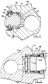
- Figures 23 and 24 show in greater detail a preferred form of polyphase modulated bias unit operating under the attenuated parallel hydraulic system shown in Figure 20.
- Referring to Figures 23 and 24, the
bit body 122 includes acentral bore 124 through which drilling fluid under pressure is delivered to nozzles, not shown, in theend face 126 of the bit. Fluid emerging from the nozzles serves to clean and cool the cuttingelements 128 and to convey cuttings upwardly to the surface through the annulus between the drill string and the surrounding wall of the borehole being drilled. - Spaced apart equally around the
gauge portion 130 of the bit body are fourbias actuators 132. The movable part of each actuator comprises apaddle 134 one end of which is pivotally connected to thebit body 122 by a pivotal mounting 136, the axis of which is parallel to the central longitudinal axis of the drill bit. Anabutment surface 138 on the bit body adjacent thepivot 136 co-operates with faces on thepaddle 134 to limit the inward and outward pivoting movement of the paddle. - An inner part of the
paddle 134 is pivotable into and out of arecess 140 in the bit body. Located within therecess 140 is a part-toroidal seal 142 the outer face of which is sealingly clamped to the inner surface of thepaddle 134 by adisc 144, and the inner face of thetoroidal seal 142 is clamped to the inner surface of therecess 140 by afurther disc 146 formed with two spacedapertures - An
inlet passage 150 formed in the bit body leads to thehole 148 and places the interior of theseal 142 into communication with afurther passage 152 in a cylindricalvalve carrier block 154 mounted across thecentral bore 124 of the bit body. Thevalve carrier 154 is formed with a number ofbypass passages 156 which allow the flow of drilling fluid past thevalve carrier 154 and to the lower part of thecentral bore 124 from where the fluid is delivered to the nozzles. - The
valve carrier 154 supports avalve assembly 158. The assembly comprises abearing disc 160 mounted in the bottom of acylindrical recess 162 in the valve carrier and formed with fourvalve apertures 164. Only one of theapertures 164 is shown in Figure 23 registering with theinlet passage 152 leading to theactuator 132. However, thedisc 160 is formed with four apertures each of which registers with the inlet passage of a different one of the four actuators provided around the periphery of the drill bit. - Rotatable over the
disc 160 is a valve disc 166 which is formed with asingle aperture 168 and is secured to the lower end of acontrol shaft 170. Theaperture 168 is circumferentially elongate so that it may overlap more than one of theapertures 164 at a time. Thecontrol shaft 170 passes through anelongate labyrinth choke 172, the lower end of which is screw threaded into the upper part of therecess 162 in the valve carrier. The engaging surfaces of thediscs 160 and 166 are preferably diamond faced. - The
labyrinth choke 172 corresponds to theprimary choke 110 in Figure 20, and may be selected according to the pressure requirements at the drilling site. By passing the control shaft through thelabyrinth choke 172 itself, the necessity of passing the shaft through a contacting rotary pressure seal is avoided. This eliminates the extra torque requirement which would result from the friction applied by such a contact seal. - The
control shaft 170 may comprise the output shaft of a roll stabilised system of any of the kinds referred to in British Patent Application No. 9213253.9. The roll stabilised system causes theshaft 170 to remain stationary in space as the drill bit rotates and consequently the fourapertures 164 andinlet passages 152 are brought successively opposite theaperture 168 once during each revolution of the drill bit. Thus, theactuators 132 are successively brought into communication with the drilling fluid pressure, attenuated by thelabyrinth choke 172. - When the
aperture 168 begins to overlap theaperture 164 associated with aparticular actuator 132, the interior of thetoroidal seal 142 of that actuator is placed in communication with the attenuated drilling fluid pressure by means of theinlet passages cavity 143 enclosed by theseal 142 and theplates paddle 134 outwardly against the wall of the surrounding formation and thus biases the drill bit in the opposite direction. Since theactuators 132 are actuated successively, each being actuated once during each revolution of the drill bit, the resulting bias to the drill bit is always in the same lateral direction. This direction depends on the rotational orientation of theshaft 170 and disc 166 in space. Thus the direction of displacement of the drill bit during drilling, and hence consequent deviation of the borehole, may be determined by appropriate selection of the rotational position of thecontrol shaft 170. - As the drill bit rotates from the position where the
aperture 168 is in communication with theaperture 164 of a particular actuator, thepaddle 134 of that actuator begins to be urged towards itsrecess 14 by the pressure of the formation, and the drilling fluid within thecavity 143 is exhausted to the annulus between the bit body and the surrounding formation. This is achieved by afurther passage 174 in the bit body which leads from thehole 149 opening into therecess 140 and is generally parallel to theinlet passage 150. Theexhaust passage 174 of theactuator 132 shown in Figures 23 and 24 may be seen in Figure 24, but is not shown in Figure 23. However, Figure 23 shows thecorresponding exhaust passage 174′ which leads from the similar actuator (not shown) which is located diametrically opposite theactuator 132 on the drill bit. Eachexhaust passage angled passage 176 in the bit body which leads upwardly and outwardly to theannulus 178, eachpassage 176 being formed with a plurality of longitudinally spaced chokes 180. The size of thechokes 180 is selected to cause sufficient pressure to build up in thecavity 143 when the valve is switched to that cavity, while allowing the pressure to dissipate sufficiently rapidly subsequently. - In known manner the gauge portion of the drill bit will normally be provided with abrasion-resistant elements. Such elements may also be mounted in the outer formation-engaging surface of each
paddle 134, as indicated at 182 in Figure 24. - Although the
disc valve assembly 158 is preferably operated by the control shaft of a roll stabilised system as disclosed in British Specification No. 921353.9, it will be appreciated that other means may be provided for operating the valve in synchronism with rotation of the drill bit. For example the valve may be operated by an electric motor or other servo mechanism controlled by signals from an appropriate instrument package. Furthermore, thedisc valve assembly 158 is shown by way of example only, and it will be appreciated that other forms of hydraulic switching valve mechanism may be employed. - Figures 25-29 show other forms of bias actuator. In each case the valve arrangement controlling the flow of drilling fluid to and from the actuator is not shown but may be of any of the kinds described herein in relation to other embodiments of the invention.
- Figure 25 is a similar view to Figure 24 showing an alternative form of bias actuator. Again, four such actuators will be provided spaced equally apart around the periphery of the drill bit or separate bias unit.
- The
actuator 182 of Figure 25 comprises again apaddle 184 pivotally mounted at 186 on the bit body and projecting partly into arecess 188 formed in the bit body. In this case, however, the inner end of aninward projection 190 on thepaddle 184 is connected to the bit body by a fabric-reinforced elastomeric annular rollingdiaphragm 192. The inner periphery of thediaphragm 192 is clamped to the inner surface of theextension 190 by aplate 194 and the outer periphery is clamped to the bit body by clampingrings 196 in therecess 188. Anenclosed cavity 198 is thus formed between thediaphragm 192 and the bottom of therecess 188 and aninlet port 200 leads into this cavity and is connected by passages (not shown) to the control valve assembly which may be of the kind indicated at 158 in Figure 23 or of any other appropriate kind. Anexhaust port 202 leads from thecavity 198 and communicates with the annulus via an exhaust choke similar to the chokedpassage 176 of Figure 23. - As is well known, a rolling diaphragm has an annular portion which is generally of elongate U-shape in cross-section and extends between the surfaces of the relatively movable parts, as shown in Figure 25, so as to permit a substantial degree of relative movement between the parts, i.e. the
paddle 184 and the bit body, without imposing undue strain on the diaphragm. - Figure 26 shows a further form of
actuator 204, again in the form of apaddle 206 pivotally mounted at 208 on the bit body. In this case the movable seal between thepaddle 206 and the bit body comprises a compression/shear seal 210. - The
seal 210 is connected between a generally conicalcentral support element 212 on the inner surface of thepaddle 206 and a surrounding conical surface within anannular ring 214 in screw-threaded engagement with the peripheral wall of therecess 216 in the bit body. - The
seal assembly 210 comprises a number of laminations ofelastomer 218 bonded between rigid conical separation rings 220. The inner ends of therings 220 are formed with projectingconical flanges 222 which serve as stops to limit the travel of each lamination relative to the adjacent one. Again the purpose of theseal assembly 210 is to permit inward and outward pivoting movement of thepaddle 206 while forming a seal for thechamber 224 between the paddle and the bottom wall of therecess 216. Aninlet passage 226 for drilling fluid leads into thechamber 224 and anoutlet passage 228 leads to the annulus, as previously described. - Figure 27 illustrates a further alternative arrangement which is somewhat similar to the embodiment of Figure 25 in that the
actuator 230 comprises apaddle 232 which is pivotally mounted at 234 on the bit body and where the seal between the paddle and the bit body is provided by a rollingdiaphragm 236. In this case, however, the motion of the paddle is made to follow the motion of a control element which is constrained to move sinusoidally. - In this case, the inner surface of the
paddle 232 receives a generally cup-shapedinsert 238 which provides an inwardly facing blind passage 240 communicating with thechamber 242 between the rollingdiaphragm 236 and the bottom of therecess 244 in the bit body. - Slidable within the passage 240 is an elongate valve element 246 which is mounted on the end of a sliding
shaft 248 which extends radially through abearing 250 in the bit body and projects into thecentral bore 252. - The end of the
shaft 248 is formed with a Scotch yoke mechanism comprising a transverseelongate slot 254 in which engages aneccentric pin 256 on ashaft 258 extending axially along thebore 252. - The outer end of the valve element 246 co-operates with an
outlet aperture 260 in the wall of the passage 240 which outlet aperture communicates through a passage 262 with theannulus 264 between the bit body and the surrounding formation (not shown). - The
shaft 258 is coupled to the control shaft of the roll stabilised assembly referred to previously and thus remains stationary in space as the bit rotates about it. Consequently, as the bit rotates the valve element 246 moves inwardly and outwardly sinusoidally as a result of being engaged by the eccentrically locatedpin 256. As the valve element 246 moves outwardly it closes theaperture 260. Thechamber 242 behind the rollingdiaphragm 236, which is in communication with the central bore of the drill bit via aninlet port 266, is pressurised causing thepaddle 232 to move outwardly. Such movement continues until theaperture 260 has moved clear of the end of the valve element 246 so that the interior of thechamber 242 is again vented to the annulus. - As the valve element 246 then moves inwardly again, the
paddle 232 is urged inwardly, as a result of the external forces acting thereon, drilling fluid continuing to escape through the passage 262. When a position is reached where theaperture 260 is again covered by the valve element 246, thepaddle 232 begins to move outwardly again. - The inward and outward movement of the
paddle 232 therefore follows the inward and outward movement of the valve element 246 and is thus in synchronism with rotation of the drill bit. - The three other actuators on the drill bit are similarly arranged and all have valve element shafts corresponding to
shaft 248 which are in engagement with theeccentric pin 256. The four valve elements corresponding to 246 are thus moved successively inwardly and outwardly during each rotation, with consequent successive inward and outward movement of the four paddles corresponding to paddle 232. - Figure 28 shows a further alternative arrangement in which the
actuator 268 comprises aslidable piston element 270 instead of a hingedly mounted paddle. In this case thepiston element 270 is slidable within anannular cylinder element 272 which is screw-threaded into arecess 274 in thebit body 276. Adiaphragm 278 is clamped between the inner end of thecylinder element 272 so as to define achamber 280 between thediaphragm 278 and thebottom 282 of the recess. As in the previous arrangements aninlet passage 284 leads into thechamber 280 and anoutlet exhaust passage 286 leads from the chamber. - An elastomer bellows
seal 288 is connected between the external part of thepiston 270 and the external part of thecylinder 272 and a slidingseal 290 is disposed between the inner periphery of thecylinder 272 and thepiston 270. - The space between the outer bellows seal 288 and the
inner diaphragm 278 is filled with a clean lubricating fluid such as oil and it will be appreciated that this does not at any time come into contact with the drilling fluid and remains uncontaminated. This prevents the loss of performance which such contamination could cause. Thediaphragm 278 and bellows seal 288 may be formed from a fabric or other porous material so that any leakage of lubricating fluid may be made up by passage of drilling fluid through the material, which fluid is effectively filtered by its passage through the material. - As the
chamber 280 is pressurised by being placed in communication with the central bore of the drill bit, thepiston 270 is urged outwardly against the formation surrounding the borehole and when thechamber 280 is placed into communication with the annulus, via the exhaust bore 286, as described in relation to the earlier arrangement, thepiston 270 moves inwardly. A pin and slot arrangement 292 is provided to limit the inward and outward movement of thepiston 270. - Figure 29 shows a further form of actuator in which the moveable thrust member is again in the form of a
paddle 308 pivotably mounted at 310 on the bit body. In this case the inner surface of thepaddle 308 is connected to the bottom of a recess 312 in thebit body 314 by generally cylindrical metal bellows 316. The bellows define avariable volume cavity 318 between the bottom of the recess 312 and the inner surface of thepaddle 308 and communicating with this cavity are aninlet passage 320 and outlet passage 322. - The flow of drilling fluid to and from the
cavity 318 through theinlet passage 320 and outlet passage 322 is controlled in synchronism with rotation of the bias unit by suitable valve means in any of the ways previously described. When thecavity 318 is pressurised thepaddle 308 is urged outwardly away from thebody 314, and when thecavity 318 is placed in communication with the annulus the paddle is free to move inwardly. - In order to prevent debris entrained in the drilling fluid from fouling the peripheral surfaces of the metal bellows, the bellows may be enclosed between inner and outer flexible "bags" 324 and 326. Since the purpose of the bags is to prevent debris finding its way onto the metal bellows, the bags may be formed from woven fabric or other porous material. However, it will be appreciated that even if the bags are of non-porous material, such as an impervious elastomer, this will not interfere with the operation of the bellows 316, provided that the bags are of sufficient size to permit the appropriate extension and retraction of the bellows.
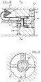
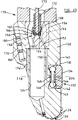
- Figures 30 and 31 show diagrammatically a further form of PDC (polycrystalline diamond compact) drill bit incorporating a synchronous modulated bias unit, in accordance with the invention, for effecting steering of the bit during rotary drilling.
- The drill bit comprises a
bit body 350 having ashank 351 for connection to the drill string and acentral passage 352 for supplying drilling fluid through bores, such as 353, to nozzles such as 354 in the face of the bit. - The face of the bit is formed with a number of
blades 355, for example four blades, each of which carries, spaced apart along its length, a plurality of PDC cutters (not shown). Each cutter may be of the kind comprising a circular tablet, made up of a superhard table of polycrystalline diamond, providing the front cutting face, bonded to a substrate of cemented tungsten carbide. Each cutting element is brazed to a tungsten carbide post or stud which is received within a socket in theblade 355 on the bit body. - The
gauge portion 357 of the bit body is formed with four circumferentially spaced kickers which, in use, engage the walls of the borehole being drilled and are separated by junk slots. - PDC drill bits having the features just described are generally well known and such features do not therefore require to be described or illustrated in further detail. The drill bit of Figures 30 and 31, however, incorporates a synchronous modulated bias unit according to the invention which allows the bit to be steered in the course of rotary drilling and the features of such bias unit will now be described.
- Each of the four
kickers 358 of the drill bit incorporates apiston assembly matching bore 363 in the bit body. Theopposite piston assemblies parallel rods 364 which are slideable through correspondingly shaped guide bores through the bit body so that the piston assemblies are rigidly connected together at a constant distance apart. The other twopiston assemblies rods 365 extending at right angles below therespective rods 364. - The outer surfaces of the
piston assemblies assembly 360 in Figure 10, is flush with the surface of its kicker, the outer surface of the opposite assembly, such as 359 in Figure 10, projects a short distance beyond the outer surface of its associated kicker. - Each piston assembly is separated from the inner end of the
bore 363 in which it is slideable by aflexible diaphragm 366 so as to define anenclosed chamber 367 between the diaphragm and the inner wall of thebore 363. The upper end of eachchamber 367 communicates through aninclined bore 368 with thecentral passage 352 in the bit body, achoke 369 being located in thebore 368. - The lower end of each
chamber 367 communicates through abore 370 with a cylindrical radially extendingvalve chamber 371 closed off by a fixed plug 372. Anaperture 373 places the inner end of thevalve chamber 371 in communication with a part 352a of thecentral passage 352 below a circular spider/choke 377 mounted in thepassage 352. Theaperture 373 is controlled by apoppet valve 374 mounted on arod 375. The inner end of eachrod 375 is slidingly supported in a blind bore in the inner end of the plug 372. - The
valve rod 375 extends inwardly through eachaperture 373 and is supported in a slidingbearing 376 depending from thecircular spider 377. Thespider 377 has vertical throughpassages 378 to permit the flow of drilling fluid past the spider to thenozzles 354 in the bit face, and therefore also acts as a choke to create a pressure drop in the fluid. Acontrol shaft 379 extends axially through the centre of thespider 377 and is supported therein bybearings 380. The lower end of thecontrol shaft 379 carries a cam member 381 which cooperates with the fourvalve rods 375 to operate thepoppet valves 374. - The upper end of the
control shaft 379 is detachably coupled to anoutput shaft 385 which is mounted axially on the carrier of a roll stabilised assembly of any of the kinds previously described. The coupling may be in the form of amule shoe 386 which, as is well known, is a type of readily engageable and disengageable coupling which automatically connects two shafts in a predetermined relative rotational orientation to one another. Oneshaft 379 carries a transverse pin which is guided into an open-ended axial slot on a coupling member on theother shaft 385, by engagement with a peripheral cam surface on the coupling member. During steered directional drilling theshafts - As the drill bit rotates relatively to the
shaft 379 the cam member 381 opens and closes the fourpoppet valves 374 in succession. When apoppet valve 374 is open drilling fluid from thecentral passage 352 flows into the associatedchamber 367 through thebore 368 and then flows out of thechamber 367 through thebore 370,valve chamber 371, andaperture 373 into the lower end 352a of thepassage 352, which is at a lower pressure than the upper part of the passage due to the pressure drop caused by thespider 377 and afurther choke 382 extending across thepassage 352 above thespider 377. This throughflow of drilling fluid flushes any debris from thebores chamber 367. - The
further choke 382 is replaceable, and is selected according to the total pressure drop required across thechoke 382 andspider 377, having regard to the particular pressure and flow rate of the drilling fluid being employed. - As the drill bit rotates to a position where the
poppet valve 374 is closed, the pressure in thechamber 367 rises causing the associated piston assembly to be displaced outwardly with respect to the bit body. Simultaneously, due to their interconnection by therods - Accordingly, the displacement of the piston assemblies is modulated in synchronism with rotation of the bit body about the
control shaft 379. As a result of the modulation of the displacement of the piston assemblies, a periodic lateral displacement is applied to the drill bit in a constant direction as the bit rotates, such direction being determined by the angular orientation of theshafts - When it is required to drill without deviation, the
control shafts - In certain of the arrangements described above, the flow of drilling fluid into and out of the cavity in each actuator takes place through a single passage. For example the embodiments of Figures 6 to 17 are of this type. In other arrangements, however, for example of the kind shown in Figures 20 to 31, drilling fluid under pressure is delivered to the cavity through an inlet passage and fluid escapes from the cavity to the annulus through a separate outlet or exhaust passage.
- The latter arrangement is preferred since it tends to prevent debris entrained in the fluid settling and being retained within the cavity. In the more preferred arrangements the operation is such that, at some stage in each operation of the actuator, the inlet and exhaust passages are open simultaneously so that there is a flushing through of drilling fluid which washes away any debris. It will be appreciated that if debris were to be allowed to settle out and accumulate in the cavity, this would lead to eventual clogging of the cavity and perhaps non functioning of the bias unit.
- Those arrangements described above having only a single combined inlet and outlet passage could be modified so as to provide, instead, separate inlet and outlet passages.
- It should be emphasised that although, for convenience, the modulated bias systems described above have been shown incorporated in a special drill bit, the present invention includes arrangements where such modulated bias systems are not incorporated in the drill bit itself but are provided in a separate sub-unit designed to form a part of the bottomhole assembly above the drill bit, and thus to allow steerable rotary drilling with any existing or conventionally designed form of drill bit. Also, the invention is not exclusively for use with PDC drill bits, but a modulated bias unit according to the invention might be incorporated in, or used in combination with, a roller cone or natural diamond bit.
Claims (40)
- A modulated bias unit, for controlling the direction of drilling of a rotary drill bit when drilling boreholes in subsurface formations, comprising:
a body structure having an outer peripheral surface;
at least one cavity located at said outer peripheral surface;
a movable thrust member partly projecting outwardly of said cavity for engagement with the surrounding formation of the borehole being drilled;
means for supplying fluid under pressure to said cavity from a source of fluid under pressure to displace said movable member outwardly; and
means for modulating the pressure of fluid supplied to the cavity in synchronism with rotation of the body structure, and in selected phase relation thereto, whereby said movable member is displaced outwardly at a selected rotational orientation of the body structure. - A modulated bias unit according to Claim 1, wherein said means for modulating the pressure of fluid supplied to the cavity comprise valve means operable to place said cavity alternately in communication with an inlet flowpath leading from said source of fluid under pressure and an outlet flowpath leading to a lower pressure zone, in synchronism with rotation of the unit.
- A modulated bias unit according to Claim 1, comprising an inlet flowpath leading from said source of fluid under pressure to said cavity, an outlet flowpath leading from said cavity to a lower pressure zone, and valve means in at least one of said flowpaths operable in synchronism with rotation of the unit to modulate the pressure of fluid supplied to said cavity from said source.
- A modulated bias unit according to Claim 3, wherein the other of said inlet and outlet flowpaths includes choke means to effect a pressure drop in fluid flowing along said other flowpath.
- A modulated bias unit according to Claim 3 or Claim 4, where said valve means are located in said inlet flowpath.
- A modulated bias unit according to any of Claims 2 to 5, wherein said inlet and outlet flowpaths are separate and include separate inlet and outlet passages leading into and out of said cavity respectively.
- A modulated bias unit according to any of Claims 1 to 6, wherein there are provided a plurality of said cavities and movable thrust members, spaced substantially equally apart around the periphery of the body structure, and said means for modulating the pressure of fluid supplied to each cavity comprise valve means operable to increase the pressure of fluid supplied to each cavity in succession, as the unit rotates.
- A modulated bias unit according to Claim 7, wherein said valve means comprise a single selector valve adapted to connect an inlet, leading from said source of fluid under pressure, to each one in succession of a plurality of outlets, each of which outlets leads to a different one of said cavities.
- A modulated bias unit according to Claim 8, wherein said selector valve is a disc valve.
- A modulated bias unit according to Claim 7, wherein said valve means comprise a plurality of separate valves, each located to control the supply of fluid under pressure to a different one of said cavities, means being provided to effect operation of each valve in succession, as the unit rotates.
- A modulated bias unit according to any of Claims 1 to 10, wherein said means for modulating the pressure of fluid supplied to the cavity comprise valve means operable by a shaft which extends at least partly into a region providing said source of fluid under pressure, wherein a flowpath leading from said region to the valve means includes an annular choke to effect a pressure drop in fluid flowing along said flowpath, and wherein said shaft extends through said choke.
- A modulated bias unit according to any of Claims 1 to 11, wherein said movable thrust member is pivotally mounted on the body structure for pivotal movement about a pivot axis located to one side of said recess.
- A modulated bias unit according to Claim 12, wherein said pivot axis extends generally parallel to the axis of rotation of the modulated bias unit during drilling.
- A modulated bias unit according to Claim 12 or Claim 13, wherein said pivot axis is disposed on the leading side of the recess with respect to the direction of rotation of the modulated bias unit during drilling.
- A modulated bias unit according to any of Claims 1 to 11, wherein means are provided to constrain the movable thrust member to reciprocate linearly inwardly and outwardly with respect to said cavity.
- A modulated bias unit according to claim 15, wherein the movable thrust member is constrained to reciprocate along an axis which is parallel to a radius of the bias unit but is spaced rearwardly from said radius with respect to the direction of rotation of the unit during drilling, whereby said axis does not intersect the axis of rotation of the bias unit.
- A modulated bias unit according to Claim 7 or Claim 16, wherein said movable thrust member includes a piston portion which is slidable within a cylinder portion communicating with said cavity.
- A modulated bias unit according to claim 17, wherein flexible seals are provided at inner and outer ends of said cylinder portion to isolate the sliding engagement between the piston portion and cylinder portion from fluid both in the cavity and externally of the bias unit.
- A modulated bias unit according to Claim 18, wherein the spaces enclosed between said flexible seals are filled with lubricating fluid.
- A modulated bias unit according to any of Claims 1 to 19, wherein at least part of said cavity is defined by a flexible sealing element connected between the movable thrust member and the body structure of the unit, which cavity increases in volume as fluid under pressure is delivered thereto, so as to urge the movable thrust member outwardly with respect to the cavity.
- A modulated bias unit according to Claim 20, wherein said flexible sealing element comprises an annular element of generally C-shaped cross-section, one face of which is connected to an inner face of the movable thrust member and the opposite face of which is connected to a surface of the body structure, around an inlet and outlet for fluid under pressure, whereby said cavity is defined by the annular element, said inner face of the movable thrust member and said surface of the body structure.
- A modulated bias unit according to claim 20, wherein said flexible sealing element comprises a diaphragm connected between the movable thrust member and a surrounding wall of a recess in the body structure.
- A modulated bias unit according to Claim 22, wherein said diaphragm is a rolling diaphragm having an annular portion of elongate U-shaped cross-section between the movable thrust member and said surrounding wall of said recess.
- A modulated bias unit according to claim 20, wherein said resiliently flexible sealing element is a shear seal comprising a plurality of generally concentric annular laminations of elastomer separated by a plurality of generally concentric annular rigid laminations.
- A modulated bias unit according to Claim 24, wherein said shear seal, and the laminations thereof, are part-conical and are mounted between part-conical surfaces on the movable thrust member and recess respectively.
- A modulated bias unit according to Claim 20, wherein said flexible sealing element comprises a metal bellows, one end of which is connected to an inner face of the movable thrust member and the opposite face of which is connected to a surface of the body structure around an inlet and outlet for fluid under pressure, whereby said cavity is defined by the metal bellows, said inner face of the movable thrust member and said surface of the body structure.
- A modulated bias unit according to Claim 10, wherein the separate valve means controlling the supply of fluid under pressure to each cavity comprise an outlet in the respective movable thrust member which faces into the cavity and leads to an exhaust passage formed in the movable thrust member and leading to a lower pressure zone, and a reciprocable element located to move into and out of covering relation with said outlet as the bias unit rotates, whereby said movable thrust member is moved outwardly under the action of fluid pressure in the cavity when the outlet is covered, and is free to move inwardly when the outlet is uncovered and vents fluid pressure from the cavity through said exhaust passage.
- A modulated bias unit according to Claim 27, wherein said reciprocable element is located at the outer end of an elongate element which extends generally radially of the bias unit, the inner end of the elongate element being coupled by a Scotch yoke mechanism to a control member coaxial with the bias unit, which control member remains substantially non-rotating as the bias unit rotates.
- A modulated bias unit according to any of the preceding claims, and including at least one pair of movable thrust members diametrically oppositely disposed with respect to the central longitudinal axis of the bias unit, wherein the movable thrust members of each said pair are mechanically coupled together by connecting means extending through the body structure of the bias unit whereby as one thrust member moves outwardly the other thrust member moves inwardly by an equal amount and vice versa.
- A modulated bias unit according to Claim 29, wherein said connecting means comprise at least one connecting rod extending slidably through bearing means within the body structure, opposite ends of each rod being connected to the two thrust members respectively.
- A modulated bias unit, for controlling the direction of drilling of a rotary drill bit when drilling boreholes in subsurface formations comprising:
a body structure having an outer periphery;
a plurality of hydraulic actuator units spaced apart around the periphery of the body structure and having movable thrust members hydraulically displaceable outwardly with respect to the body structure for engagement with the formation of the borehole being drilled;
each actuator unit having an inlet passage for connection to a source of fluid under pressure and an outlet passage for communication with a lower pressure zone;
selector valve means for connecting said inlet passages in succession to said source of fluid under pressure, as the unit rotates;
choke means to create a pressure drop between the source of fluid under pressure and said selector valve means; and
further choke means in the outlet passage from each actuator unit. - A modulated bias unit, for controlling the direction of drilling of a rotary drill bit when drilling boreholes in subsurface formations comprising:
a body structure having an outer periphery;
a plurality of hydraulic actuator units spaced apart around the periphery of the body structure and having movable thrust members hydraulically displaceable outwardly with respect to the body structure for engagement with the formation of the borehole being drilled;
each actuator unit having an inlet passage for connection to a source of fluid under pressure and an outlet passage for communication with a lower pressure zone;
valve means in one of the inlet and outlet passages of each actuator unit;
choke means in the other of the inlet and outlet passages of each actuator unit; and
means for selectively operating said valve means in succession as the bias unit rotates, to place the hydraulic actuators successively in communication with the source of fluid under pressure. - A modulated bias unit according to Claim 32, wherein said choke means comprise further valve means, means being provided for selectively operating said further valve means in succession as the bias unit rotates.
- A modulated bias unit according to Claim 32, including further choke means to create a pressure drop between the source of fluid under pressure and said inlet passages of the actuator units.
- A modulated bias unit, for controlling the direction of drilling of a rotary drill bit when drilling holes in subsurface formations, comprising:
a body structure;
means for applying to the body structure a force having a lateral component at right angles to the axis of rotation of the body structure;
means for modulating said lateral force component in synchronism with rotation of the body structure, and in selected phase relation thereto, whereby the maximum value of said lateral force component is applied to the body structure at a selected rotational orientation thereof, so as to cause the body structure to become displaced laterally as drilling continues;
said means for applying the lateral force component to the body structure comprising means for supplying fluid under pressure to at least one opening in an outwardly facing surface of the body structure assembly; and
said means for modulating said lateral force component comprising means for modulating the pressure of fluid delivered to said opening. - A modulated bias unit according to Claim 35, wherein said opening comprises an outwardly facing cavity in said surface of the body structure, conduit means being provided for placing the cavity in communication with a passage in the body structure through which fluid is delivered under pressure to the cavity.
- A modulated bias unit according to Claim 35 or Claim 36, wherein said opening for fluid under pressure is provided in an outwardly facing surface of the body structure itself.
- A modulated bias unit according to any one of Claims 35 to 37, wherein said means for modulating the pressure of fluid delivered to said opening comprise a valve disposed in the path of flow of fluid to the opening, means being provided to operate said valve periodically in synchronism with rotation of the body structure and in said selected phase relation thereto.
- A modulated bias unit according to Claim 38, wherein said valve is arranged to switch the flow of fluid on and off periodically.
- A drill bit for drilling boreholes in subsurface formations comprising a bit body having a shank for connection to a drill string, an inner passage for supply drilling fluid under pressure to the bit, and a plurality of cutting elements mounted on the bit body, the bit body including a modulated bias unit according to any of the preceding claims.
Applications Claiming Priority (4)
| Application Number | Priority Date | Filing Date | Title |
|---|---|---|---|
| GB919118618A GB9118618D0 (en) | 1991-08-30 | 1991-08-30 | A drilling system and method |
| GB9118618 | 1991-08-30 | ||
| US901748 | 1992-06-22 | ||
| US07/901,748 US5265682A (en) | 1991-06-25 | 1992-06-22 | Steerable rotary drilling systems |
Publications (2)
| Publication Number | Publication Date |
|---|---|
| EP0530045A1 true EP0530045A1 (en) | 1993-03-03 |
| EP0530045B1 EP0530045B1 (en) | 1997-04-23 |
Family
ID=26299463
Family Applications (1)
| Application Number | Title | Priority Date | Filing Date |
|---|---|---|---|
| EP92307882A Expired - Lifetime EP0530045B1 (en) | 1991-08-30 | 1992-08-28 | Modulated bias units for steerable rotary drilling systems |
Country Status (7)
| Country | Link |
|---|---|
| US (1) | US5553678A (en) |
| EP (1) | EP0530045B1 (en) |
| AU (1) | AU647957B2 (en) |
| CA (1) | CA2077177C (en) |
| DE (1) | DE69219250T2 (en) |
| GB (1) | GB2259316B (en) |
| NO (1) | NO307098B1 (en) |
Cited By (38)
| Publication number | Priority date | Publication date | Assignee | Title |
|---|---|---|---|---|
| US5520255A (en) * | 1994-06-04 | 1996-05-28 | Camco Drilling Group Limited | Modulated bias unit for rotary drilling |
| EP0792995A1 (en) * | 1996-02-27 | 1997-09-03 | Tracto-Technik Paul Schmidt Spezialmaschinen | Method for guiding of an earth drilling device |
| EP0841462A3 (en) * | 1996-11-06 | 1999-01-20 | Camco Drilling Group Limited | Downhole tool with at least one formation-engaging member |
| US6092610A (en) * | 1998-02-05 | 2000-07-25 | Schlumberger Technology Corporation | Actively controlled rotary steerable system and method for drilling wells |
| US6109372A (en) * | 1999-03-15 | 2000-08-29 | Schlumberger Technology Corporation | Rotary steerable well drilling system utilizing hydraulic servo-loop |
| US6158529A (en) * | 1998-12-11 | 2000-12-12 | Schlumberger Technology Corporation | Rotary steerable well drilling system utilizing sliding sleeve |
| US6691804B2 (en) * | 2001-02-20 | 2004-02-17 | William H. Harrison | Directional borehole drilling system and method |
| US6705413B1 (en) * | 1999-02-23 | 2004-03-16 | Tesco Corporation | Drilling with casing |
| US6845826B1 (en) | 2003-02-14 | 2005-01-25 | Noble Drilling Services Inc. | Saver sub for a steering tool |
| US6857484B1 (en) | 2003-02-14 | 2005-02-22 | Noble Drilling Services Inc. | Steering tool power generating system and method |
| WO2006119022A2 (en) * | 2005-04-29 | 2006-11-09 | Aps Technology, Inc. | Rotary steerable motor system for underground drilling |
| WO2007012858A1 (en) * | 2005-07-27 | 2007-02-01 | Schlumberger Holdings Limited | Steerable drilling system |
| WO2008150765A1 (en) | 2007-05-30 | 2008-12-11 | Halliburton Energy Services, Inc. | Rotary drill bit with gage pads having improved steerability and reduced wear |
| WO2009022117A1 (en) * | 2007-08-15 | 2009-02-19 | Schlumberger Technology B.V. | Stochastic bit noise control |
| WO2009022145A1 (en) | 2007-08-15 | 2009-02-19 | Schlumberger Technology B.V. | Compliantly coupled cutting/gauge pad system |
| WO2009022116A1 (en) * | 2007-08-15 | 2009-02-19 | Schlumberger Technology B.V. | Drill bit gauge pad control |
| WO2009055199A2 (en) | 2007-10-24 | 2009-04-30 | Services Petroliers Schlumberger | Morphible bit |
| WO2010092313A1 (en) * | 2009-02-13 | 2010-08-19 | Schlumberger Technology B.V. | Offset stochastic control |
| US20110000716A1 (en) * | 2009-07-06 | 2011-01-06 | Comeau Laurier E | Drill bit with a flow interrupter |
| US7971662B2 (en) * | 2008-09-25 | 2011-07-05 | Baker Hughes Incorporated | Drill bit with adjustable steering pads |
| US8087479B2 (en) * | 2009-08-04 | 2012-01-03 | Baker Hughes Incorporated | Drill bit with an adjustable steering device |
| US8205686B2 (en) * | 2008-09-25 | 2012-06-26 | Baker Hughes Incorporated | Drill bit with adjustable axial pad for controlling torsional fluctuations |
| US8534380B2 (en) | 2007-08-15 | 2013-09-17 | Schlumberger Technology Corporation | System and method for directional drilling a borehole with a rotary drilling system |
| US8720604B2 (en) | 2007-08-15 | 2014-05-13 | Schlumberger Technology Corporation | Method and system for steering a directional drilling system |
| US8727036B2 (en) | 2007-08-15 | 2014-05-20 | Schlumberger Technology Corporation | System and method for drilling |
| US8757294B2 (en) | 2007-08-15 | 2014-06-24 | Schlumberger Technology Corporation | System and method for controlling a drilling system for drilling a borehole in an earth formation |
| US8763726B2 (en) * | 2007-08-15 | 2014-07-01 | Schlumberger Technology Corporation | Drill bit gauge pad control |
| WO2016130865A1 (en) * | 2015-02-15 | 2016-08-18 | Schlumberger Technology Corporation | Displacement assembly with a displacement mechanism defining an exhaust path therethrough |
| US9500031B2 (en) | 2012-11-12 | 2016-11-22 | Aps Technology, Inc. | Rotary steerable drilling apparatus |
| US9915138B2 (en) | 2008-09-25 | 2018-03-13 | Baker Hughes, A Ge Company, Llc | Drill bit with hydraulically adjustable axial pad for controlling torsional fluctuations |
| US10113363B2 (en) | 2014-11-07 | 2018-10-30 | Aps Technology, Inc. | System and related methods for control of a directional drilling operation |
| WO2019009911A1 (en) | 2017-07-06 | 2019-01-10 | Halliburton Energy Services, Inc. | Steering assembly control valve |
| US10233700B2 (en) | 2015-03-31 | 2019-03-19 | Aps Technology, Inc. | Downhole drilling motor with an adjustment assembly |
| US10337250B2 (en) | 2014-02-03 | 2019-07-02 | Aps Technology, Inc. | System, apparatus and method for guiding a drill bit based on forces applied to a drill bit, and drilling methods related to same |
| WO2019133033A1 (en) * | 2017-12-29 | 2019-07-04 | Halliburton Energy Services, Inc. | Steering system for use with a drill string |
| US11162303B2 (en) | 2019-06-14 | 2021-11-02 | Aps Technology, Inc. | Rotary steerable tool with proportional control valve |
| GB2605358A (en) * | 2021-03-03 | 2022-10-05 | Enteq Tech Plc | Cartridge for a rotary drill bit |
| WO2022249055A1 (en) * | 2021-05-28 | 2022-12-01 | Rockatek Limited | Piston and cylinder assembly of a downhole tool, downhole tool with a piston and cylinder assembly, and method of assembling the piston and cylinder |
Families Citing this family (215)
| Publication number | Priority date | Publication date | Assignee | Title |
|---|---|---|---|---|
| US5265682A (en) * | 1991-06-25 | 1993-11-30 | Camco Drilling Group Limited | Steerable rotary drilling systems |
| GB9125778D0 (en) * | 1991-12-04 | 1992-02-05 | Anderson Charles A | Downhole stabiliser |
| US5449046A (en) * | 1993-12-23 | 1995-09-12 | Electric Power Research Institute, Inc. | Earth boring tool with continuous rotation impulsed steering |
| US6116355A (en) * | 1994-06-04 | 2000-09-12 | Camco Drilling Group Limited Of Hycalog | Choke device |
| US6857486B2 (en) | 2001-08-19 | 2005-02-22 | Smart Drilling And Completion, Inc. | High power umbilicals for subterranean electric drilling machines and remotely operated vehicles |
| GB9503827D0 (en) * | 1995-02-25 | 1995-04-19 | Camco Drilling Group Ltd | "Improvements in or relating to steerable rotary drilling systems |
| GB9503828D0 (en) * | 1995-02-25 | 1995-04-19 | Camco Drilling Group Ltd | "Improvements in or relating to steerable rotary drilling systems" |
| GB9503830D0 (en) * | 1995-02-25 | 1995-04-19 | Camco Drilling Group Ltd | "Improvements in or relating to steerable rotary drilling systems" |
| GB9503829D0 (en) * | 1995-02-25 | 1995-04-19 | Camco Drilling Group Ltd | "Improvememnts in or relating to steerable rotary drilling systems" |
| GB9517378D0 (en) * | 1995-08-24 | 1995-10-25 | Sofitech Nv | Hydraulic jetting system |
| GB2304756B (en) * | 1995-09-08 | 1999-09-08 | Camco Drilling Group Ltd | Improvement in or relating to electrical machines |
| GB9521972D0 (en) * | 1995-10-26 | 1996-01-03 | Camco Drilling Group Ltd | A drilling assembly for drilling holes in subsurface formations |
| US5740873A (en) * | 1995-10-27 | 1998-04-21 | Baker Hughes Incorporated | Rotary bit with gageless waist |
| BR9612567A (en) * | 1996-03-04 | 1999-07-20 | Vermeer Mfg Co | Directional drilling machine |
| GB2312905A (en) * | 1996-05-09 | 1997-11-12 | Camco Drilling Group Ltd | Automatically steered drill assembly |
| GB9708428D0 (en) * | 1997-04-26 | 1997-06-18 | Camco Int Uk Ltd | Improvements in or relating to rotary drill bits |
| US6318481B1 (en) * | 1998-12-18 | 2001-11-20 | Quantum Drilling Motors, Inc. | Drill string deflector sub |
| US6116354A (en) * | 1999-03-19 | 2000-09-12 | Weatherford/Lamb, Inc. | Rotary steerable system for use in drilling deviated wells |
| US9586699B1 (en) | 1999-08-16 | 2017-03-07 | Smart Drilling And Completion, Inc. | Methods and apparatus for monitoring and fixing holes in composite aircraft |
| US6257356B1 (en) | 1999-10-06 | 2001-07-10 | Aps Technology, Inc. | Magnetorheological fluid apparatus, especially adapted for use in a steerable drill string, and a method of using same |
| EP1163419B1 (en) | 1999-11-10 | 2004-06-16 | Schlumberger Holdings Limited | Control method for use with a steerable drilling system |
| US6491115B2 (en) | 2000-03-15 | 2002-12-10 | Vermeer Manufacturing Company | Directional drilling machine and method of directional drilling |
| US6357537B1 (en) | 2000-03-15 | 2002-03-19 | Vermeer Manufacturing Company | Directional drilling machine and method of directional drilling |
| GB0009008D0 (en) * | 2000-04-13 | 2000-05-31 | Edscer William G | Apparatus and method for directional of holes |
| US6550548B2 (en) * | 2001-02-16 | 2003-04-22 | Kyle Lamar Taylor | Rotary steering tool system for directional drilling |
| US6962214B2 (en) | 2001-04-02 | 2005-11-08 | Schlumberger Wcp Ltd. | Rotary seal for directional drilling tools |
| US6840336B2 (en) | 2001-06-05 | 2005-01-11 | Schlumberger Technology Corporation | Drilling tool with non-rotating sleeve |
| GB0120076D0 (en) | 2001-08-17 | 2001-10-10 | Schlumberger Holdings | Measurement of curvature of a subsurface borehole, and use of such measurement in directional drilling |
| US9625361B1 (en) | 2001-08-19 | 2017-04-18 | Smart Drilling And Completion, Inc. | Methods and apparatus to prevent failures of fiber-reinforced composite materials under compressive stresses caused by fluids and gases invading microfractures in the materials |
| US8515677B1 (en) | 2002-08-15 | 2013-08-20 | Smart Drilling And Completion, Inc. | Methods and apparatus to prevent failures of fiber-reinforced composite materials under compressive stresses caused by fluids and gases invading microfractures in the materials |
| US7188685B2 (en) | 2001-12-19 | 2007-03-13 | Schlumberge Technology Corporation | Hybrid rotary steerable system |
| US7036611B2 (en) | 2002-07-30 | 2006-05-02 | Baker Hughes Incorporated | Expandable reamer apparatus for enlarging boreholes while drilling and methods of use |
| US6814162B2 (en) * | 2002-08-09 | 2004-11-09 | Smith International, Inc. | One cone bit with interchangeable cutting structures, a box-end connection, and integral sensory devices |
| GB2402902B (en) * | 2003-06-19 | 2007-05-30 | William George Edscer | Forward driving system for use in drilling masonry structures |
| US7383898B2 (en) * | 2003-06-23 | 2008-06-10 | Schlumberger Technology Corporation | Inner and outer motor with eccentric stabilizer |
| US7287604B2 (en) * | 2003-09-15 | 2007-10-30 | Baker Hughes Incorporated | Steerable bit assembly and methods |
| GB2410042B (en) * | 2004-01-15 | 2006-11-15 | Schlumberger Holdings | Compensated shielded actuator apparatus and method |
| US7243739B2 (en) * | 2004-03-11 | 2007-07-17 | Rankin Iii Robert E | Coiled tubing directional drilling apparatus |
| US7287605B2 (en) | 2004-11-02 | 2007-10-30 | Scientific Drilling International | Steerable drilling apparatus having a differential displacement side-force exerting mechanism |
| GB0503742D0 (en) * | 2005-02-11 | 2005-03-30 | Hutton Richard | Rotary steerable directional drilling tool for drilling boreholes |
| US8827006B2 (en) * | 2005-05-12 | 2014-09-09 | Schlumberger Technology Corporation | Apparatus and method for measuring while drilling |
| US7604072B2 (en) * | 2005-06-07 | 2009-10-20 | Baker Hughes Incorporated | Method and apparatus for collecting drill bit performance data |
| US7849934B2 (en) * | 2005-06-07 | 2010-12-14 | Baker Hughes Incorporated | Method and apparatus for collecting drill bit performance data |
| US8376065B2 (en) * | 2005-06-07 | 2013-02-19 | Baker Hughes Incorporated | Monitoring drilling performance in a sub-based unit |
| US8100196B2 (en) * | 2005-06-07 | 2012-01-24 | Baker Hughes Incorporated | Method and apparatus for collecting drill bit performance data |
| US20070030167A1 (en) * | 2005-08-04 | 2007-02-08 | Qiming Li | Surface communication apparatus and method for use with drill string telemetry |
| US7503405B2 (en) * | 2005-11-21 | 2009-03-17 | Hall David R | Rotary valve for steering a drill string |
| US8297375B2 (en) | 2005-11-21 | 2012-10-30 | Schlumberger Technology Corporation | Downhole turbine |
| US8528664B2 (en) | 2005-11-21 | 2013-09-10 | Schlumberger Technology Corporation | Downhole mechanism |
| US8297378B2 (en) | 2005-11-21 | 2012-10-30 | Schlumberger Technology Corporation | Turbine driven hammer that oscillates at a constant frequency |
| US7730972B2 (en) * | 2005-11-21 | 2010-06-08 | Schlumberger Technology Corporation | Downhole turbine |
| US7641003B2 (en) | 2005-11-21 | 2010-01-05 | David R Hall | Downhole hammer assembly |
| US8316964B2 (en) | 2006-03-23 | 2012-11-27 | Schlumberger Technology Corporation | Drill bit transducer device |
| US8522897B2 (en) | 2005-11-21 | 2013-09-03 | Schlumberger Technology Corporation | Lead the bit rotary steerable tool |
| US8225883B2 (en) * | 2005-11-21 | 2012-07-24 | Schlumberger Technology Corporation | Downhole percussive tool with alternating pressure differentials |
| US7753144B2 (en) | 2005-11-21 | 2010-07-13 | Schlumberger Technology Corporation | Drill bit with a retained jack element |
| US8267196B2 (en) | 2005-11-21 | 2012-09-18 | Schlumberger Technology Corporation | Flow guide actuation |
| US7617886B2 (en) * | 2005-11-21 | 2009-11-17 | Hall David R | Fluid-actuated hammer bit |
| US7360610B2 (en) * | 2005-11-21 | 2008-04-22 | Hall David R | Drill bit assembly for directional drilling |
| US7571780B2 (en) | 2006-03-24 | 2009-08-11 | Hall David R | Jack element for a drill bit |
| US7549489B2 (en) | 2006-03-23 | 2009-06-23 | Hall David R | Jack element with a stop-off |
| US8360174B2 (en) | 2006-03-23 | 2013-01-29 | Schlumberger Technology Corporation | Lead the bit rotary steerable tool |
| WO2007103245A2 (en) * | 2006-03-02 | 2007-09-13 | Baker Hughes Incorporated | Automated steerable hole enlargement drilling device and methods |
| US8875810B2 (en) | 2006-03-02 | 2014-11-04 | Baker Hughes Incorporated | Hole enlargement drilling device and methods for using same |
| GB0706650D0 (en) * | 2006-04-06 | 2007-05-16 | Tracto Technik | Method for operating an actuator and apparatus |
| US7413034B2 (en) * | 2006-04-07 | 2008-08-19 | Halliburton Energy Services, Inc. | Steering tool |
| US8162076B2 (en) * | 2006-06-02 | 2012-04-24 | Schlumberger Technology Corporation | System and method for reducing the borehole gap for downhole formation testing sensors |
| GB0615883D0 (en) * | 2006-08-10 | 2006-09-20 | Meciria Ltd | Steerable rotary directional drilling tool for drilling boreholes |
| US8191651B2 (en) * | 2006-08-11 | 2012-06-05 | Hall David R | Sensor on a formation engaging member of a drill bit |
| GB2468426B (en) * | 2006-10-27 | 2011-07-06 | Schlumberger Holdings | Well drilling apparatus and methods |
| US7954401B2 (en) | 2006-10-27 | 2011-06-07 | Schlumberger Technology Corporation | Method of assembling a drill bit with a jack element |
| US7942213B2 (en) * | 2006-10-27 | 2011-05-17 | Schlumberger Technology Corporation | Using hydrostatic bearings for downhole applications |
| RU2462577C2 (en) | 2006-12-04 | 2012-09-27 | Бейкер Хьюз Инкорпорейтед | Expanding reamer for holes reaming and method of hole reaming |
| US8657039B2 (en) | 2006-12-04 | 2014-02-25 | Baker Hughes Incorporated | Restriction element trap for use with an actuation element of a downhole apparatus and method of use |
| US20080142268A1 (en) * | 2006-12-13 | 2008-06-19 | Geoffrey Downton | Rotary steerable drilling apparatus and method |
| US7866416B2 (en) | 2007-06-04 | 2011-01-11 | Schlumberger Technology Corporation | Clutch for a jack element |
| US8469120B2 (en) * | 2007-06-13 | 2013-06-25 | Exxonmobil Upstream Research Company | Methods and apparatus for controlling cutting ribbons during a drilling operation |
| US7669669B2 (en) * | 2007-07-30 | 2010-03-02 | Schlumberger Technology Corporation | Tool face sensor method |
| US7866415B2 (en) * | 2007-08-24 | 2011-01-11 | Baker Hughes Incorporated | Steering device for downhole tools |
| US7721826B2 (en) | 2007-09-06 | 2010-05-25 | Schlumberger Technology Corporation | Downhole jack assembly sensor |
| US7967083B2 (en) * | 2007-09-06 | 2011-06-28 | Schlumberger Technology Corporation | Sensor for determining a position of a jack element |
| US8442769B2 (en) * | 2007-11-12 | 2013-05-14 | Schlumberger Technology Corporation | Method of determining and utilizing high fidelity wellbore trajectory |
| US20090133931A1 (en) * | 2007-11-27 | 2009-05-28 | Schlumberger Technology Corporation | Method and apparatus for hydraulic steering of downhole rotary drilling systems |
| US8813869B2 (en) * | 2008-03-20 | 2014-08-26 | Schlumberger Technology Corporation | Analysis refracted acoustic waves measured in a borehole |
| US7779933B2 (en) * | 2008-04-30 | 2010-08-24 | Schlumberger Technology Corporation | Apparatus and method for steering a drill bit |
| EP2304174A4 (en) | 2008-05-22 | 2015-09-23 | Schlumberger Technology Bv | Downhole measurement of formation characteristics while drilling |
| US8061444B2 (en) * | 2008-05-22 | 2011-11-22 | Schlumberger Technology Corporation | Methods and apparatus to form a well |
| CA2725133A1 (en) | 2008-05-23 | 2009-11-26 | Schlumberger Canada Limited | Drilling wells in compartmentalized reservoirs |
| US7818128B2 (en) * | 2008-07-01 | 2010-10-19 | Schlumberger Technology Corporation | Forward models for gamma ray measurement analysis of subterranean formations |
| US8960329B2 (en) * | 2008-07-11 | 2015-02-24 | Schlumberger Technology Corporation | Steerable piloted drill bit, drill system, and method of drilling curved boreholes |
| US8746368B2 (en) * | 2008-08-13 | 2014-06-10 | Schlumberger Technology Corporation | Compliantly coupled gauge pad system |
| US20100101864A1 (en) * | 2008-10-27 | 2010-04-29 | Olivier Sindt | Anti-whirl drill bits, wellsite systems, and methods of using the same |
| US20100101867A1 (en) * | 2008-10-27 | 2010-04-29 | Olivier Sindt | Self-stabilized and anti-whirl drill bits and bottom-hole assemblies and systems for using the same |
| US20100108390A1 (en) * | 2008-11-04 | 2010-05-06 | Baker Hughes Incorporated | Apparatus and method for controlling fluid flow in a rotary drill bit |
| US8146679B2 (en) * | 2008-11-26 | 2012-04-03 | Schlumberger Technology Corporation | Valve-controlled downhole motor |
| US7819666B2 (en) * | 2008-11-26 | 2010-10-26 | Schlumberger Technology Corporation | Rotating electrical connections and methods of using the same |
| US8179278B2 (en) * | 2008-12-01 | 2012-05-15 | Schlumberger Technology Corporation | Downhole communication devices and methods of use |
| US8376366B2 (en) * | 2008-12-04 | 2013-02-19 | Schlumberger Technology Corporation | Sealing gland and methods of use |
| US7980328B2 (en) * | 2008-12-04 | 2011-07-19 | Schlumberger Technology Corporation | Rotary steerable devices and methods of use |
| US8276805B2 (en) | 2008-12-04 | 2012-10-02 | Schlumberger Technology Corporation | Method and system for brazing |
| US8157024B2 (en) * | 2008-12-04 | 2012-04-17 | Schlumberger Technology Corporation | Ball piston steering devices and methods of use |
| US8783382B2 (en) * | 2009-01-15 | 2014-07-22 | Schlumberger Technology Corporation | Directional drilling control devices and methods |
| US7975780B2 (en) * | 2009-01-27 | 2011-07-12 | Schlumberger Technology Corporation | Adjustable downhole motors and methods for use |
| US8365843B2 (en) * | 2009-02-24 | 2013-02-05 | Schlumberger Technology Corporation | Downhole tool actuation |
| US9127521B2 (en) * | 2009-02-24 | 2015-09-08 | Schlumberger Technology Corporation | Downhole tool actuation having a seat with a fluid by-pass |
| US8061455B2 (en) * | 2009-02-26 | 2011-11-22 | Baker Hughes Incorporated | Drill bit with adjustable cutters |
| US9976360B2 (en) | 2009-03-05 | 2018-05-22 | Aps Technology, Inc. | System and method for damping vibration in a drill string using a magnetorheological damper |
| US20100243242A1 (en) * | 2009-03-27 | 2010-09-30 | Boney Curtis L | Method for completing tight oil and gas reservoirs |
| US8301382B2 (en) | 2009-03-27 | 2012-10-30 | Schlumberger Technology Corporation | Continuous geomechanically stable wellbore trajectories |
| US7650951B1 (en) | 2009-04-16 | 2010-01-26 | Hall David R | Resettable actuator for downhole tool |
| WO2010121344A1 (en) | 2009-04-23 | 2010-10-28 | Schlumberger Holdings Limited | A drill bit assembly having aligned features |
| CA2795482C (en) | 2009-04-23 | 2014-07-08 | Schlumberger Canada Limited | Drill bit assembly having electrically isolated gap joint for electromagnetic telemetry |
| US9022144B2 (en) | 2009-04-23 | 2015-05-05 | Schlumberger Technology Corporation | Drill bit assembly having electrically isolated gap joint for measurement of reservoir properties |
| US8701799B2 (en) | 2009-04-29 | 2014-04-22 | Schlumberger Technology Corporation | Drill bit cutter pocket restitution |
| US8322416B2 (en) | 2009-06-18 | 2012-12-04 | Schlumberger Technology Corporation | Focused sampling of formation fluids |
| US8297381B2 (en) | 2009-07-13 | 2012-10-30 | Baker Hughes Incorporated | Stabilizer subs for use with expandable reamer apparatus, expandable reamer apparatus including stabilizer subs and related methods |
| US8919459B2 (en) * | 2009-08-11 | 2014-12-30 | Schlumberger Technology Corporation | Control systems and methods for directional drilling utilizing the same |
| US8469104B2 (en) * | 2009-09-09 | 2013-06-25 | Schlumberger Technology Corporation | Valves, bottom hole assemblies, and method of selectively actuating a motor |
| US8307914B2 (en) * | 2009-09-09 | 2012-11-13 | Schlumberger Technology Corporation | Drill bits and methods of drilling curved boreholes |
| US9175520B2 (en) | 2009-09-30 | 2015-11-03 | Baker Hughes Incorporated | Remotely controlled apparatus for downhole applications, components for such apparatus, remote status indication devices for such apparatus, and related methods |
| WO2011041562A2 (en) | 2009-09-30 | 2011-04-07 | Baker Hughes Incorporated | Remotely controlled apparatus for downhole applications and methods of operation |
| WO2011041521A2 (en) | 2009-09-30 | 2011-04-07 | Baker Hughes Incorporated | Earth-boring tools having expandable cutting structures and methods of using such earth-boring tools |
| AU2010310816B2 (en) | 2009-10-20 | 2016-01-28 | Schlumberger Technology B.V. | Methods for characterization of formations, navigating drill paths, and placing wells in earth boreholes |
| US8777598B2 (en) * | 2009-11-13 | 2014-07-15 | Schlumberger Technology Corporation | Stators for downwhole motors, methods for fabricating the same, and downhole motors incorporating the same |
| US20110116961A1 (en) | 2009-11-13 | 2011-05-19 | Hossein Akbari | Stators for downhole motors, methods for fabricating the same, and downhole motors incorporating the same |
| US9347266B2 (en) * | 2009-11-13 | 2016-05-24 | Schlumberger Technology Corporation | Stator inserts, methods of fabricating the same, and downhole motors incorporating the same |
| US8245781B2 (en) | 2009-12-11 | 2012-08-21 | Schlumberger Technology Corporation | Formation fluid sampling |
| US8235145B2 (en) * | 2009-12-11 | 2012-08-07 | Schlumberger Technology Corporation | Gauge pads, cutters, rotary components, and methods for directional drilling |
| US8235146B2 (en) | 2009-12-11 | 2012-08-07 | Schlumberger Technology Corporation | Actuators, actuatable joints, and methods of directional drilling |
| US8905159B2 (en) * | 2009-12-15 | 2014-12-09 | Schlumberger Technology Corporation | Eccentric steering device and methods of directional drilling |
| US8473435B2 (en) * | 2010-03-09 | 2013-06-25 | Schlumberger Technology Corporation | Use of general bayesian networks in oilfield operations |
| US8281880B2 (en) | 2010-07-14 | 2012-10-09 | Hall David R | Expandable tool for an earth boring system |
| US8172009B2 (en) | 2010-07-14 | 2012-05-08 | Hall David R | Expandable tool with at least one blade that locks in place through a wedging effect |
| US8353354B2 (en) | 2010-07-14 | 2013-01-15 | Hall David R | Crawler system for an earth boring system |
| SA111320627B1 (en) | 2010-07-21 | 2014-08-06 | Baker Hughes Inc | Wellbore Tool With Exchangable Blades |
| US8694257B2 (en) | 2010-08-30 | 2014-04-08 | Schlumberger Technology Corporation | Method for determining uncertainty with projected wellbore position and attitude |
| CN103221626B (en) * | 2010-09-09 | 2015-07-15 | 国民油井华高有限公司 | Downhole rotary drilling apparatus with formation-interfacing members and control system |
| US8869916B2 (en) | 2010-09-09 | 2014-10-28 | National Oilwell Varco, L.P. | Rotary steerable push-the-bit drilling apparatus with self-cleaning fluid filter |
| US8939236B2 (en) | 2010-10-04 | 2015-01-27 | Baker Hughes Incorporated | Status indicators for use in earth-boring tools having expandable members and methods of making and using such status indicators and earth-boring tools |
| US9435649B2 (en) | 2010-10-05 | 2016-09-06 | Schlumberger Technology Corporation | Method and system for azimuth measurements using a gyroscope unit |
| US8365821B2 (en) | 2010-10-29 | 2013-02-05 | Hall David R | System for a downhole string with a downhole valve |
| US8640768B2 (en) | 2010-10-29 | 2014-02-04 | David R. Hall | Sintered polycrystalline diamond tubular members |
| CN103261560A (en) | 2010-11-08 | 2013-08-21 | 贝克休斯公司 | Tools for use in subterranean boreholes having expandable members and related methods |
| US9309884B2 (en) | 2010-11-29 | 2016-04-12 | Schlumberger Technology Corporation | Downhole motor or pump components, method of fabrication the same, and downhole motors incorporating the same |
| US9175515B2 (en) | 2010-12-23 | 2015-11-03 | Schlumberger Technology Corporation | Wired mud motor components, methods of fabricating the same, and downhole motors incorporating the same |
| US8708064B2 (en) * | 2010-12-23 | 2014-04-29 | Schlumberger Technology Corporation | System and method to control steering and additional functionality in a rotary steerable system |
| US20120193147A1 (en) * | 2011-01-28 | 2012-08-02 | Hall David R | Fluid Path between the Outer Surface of a Tool and an Expandable Blade |
| US20120234604A1 (en) * | 2011-03-15 | 2012-09-20 | Hall David R | Timed Steering Nozzle on a Downhole Drill Bit |
| US8844635B2 (en) | 2011-05-26 | 2014-09-30 | Baker Hughes Incorporated | Corrodible triggering elements for use with subterranean borehole tools having expandable members and related methods |
| US9080399B2 (en) * | 2011-06-14 | 2015-07-14 | Baker Hughes Incorporated | Earth-boring tools including retractable pads, cartridges including retractable pads for such tools, and related methods |
| US8890341B2 (en) | 2011-07-29 | 2014-11-18 | Schlumberger Technology Corporation | Harvesting energy from a drillstring |
| WO2013046028A2 (en) | 2011-09-27 | 2013-04-04 | Richard Hutton | Point the bit rotary steerable system |
| GB2498831B (en) | 2011-11-20 | 2014-05-28 | Schlumberger Holdings | Directional drilling attitude hold controller |
| US8960333B2 (en) | 2011-12-15 | 2015-02-24 | Baker Hughes Incorporated | Selectively actuating expandable reamers and related methods |
| US9267331B2 (en) | 2011-12-15 | 2016-02-23 | Baker Hughes Incorporated | Expandable reamers and methods of using expandable reamers |
| US8210283B1 (en) | 2011-12-22 | 2012-07-03 | Hunt Energy Enterprises, L.L.C. | System and method for surface steerable drilling |
| US9085941B2 (en) | 2012-02-10 | 2015-07-21 | David R. Hall | Downhole tool piston assembly |
| US9388638B2 (en) | 2012-03-30 | 2016-07-12 | Baker Hughes Incorporated | Expandable reamers having sliding and rotating expandable blades, and related methods |
| US9493991B2 (en) | 2012-04-02 | 2016-11-15 | Baker Hughes Incorporated | Cutting structures, tools for use in subterranean boreholes including cutting structures and related methods |
| US9068407B2 (en) | 2012-05-03 | 2015-06-30 | Baker Hughes Incorporated | Drilling assemblies including expandable reamers and expandable stabilizers, and related methods |
| US9394746B2 (en) | 2012-05-16 | 2016-07-19 | Baker Hughes Incorporated | Utilization of expandable reamer blades in rigid earth-boring tool bodies |
| CN104508230B (en) * | 2012-06-06 | 2017-07-07 | 贝克休斯公司 | With the drill bit for controlling the adjustable axially pad of the hydraulic pressure for reversing fluctuation |
| US9057223B2 (en) | 2012-06-21 | 2015-06-16 | Schlumberger Technology Corporation | Directional drilling system |
| US9140114B2 (en) | 2012-06-21 | 2015-09-22 | Schlumberger Technology Corporation | Instrumented drilling system |
| US9121223B2 (en) | 2012-07-11 | 2015-09-01 | Schlumberger Technology Corporation | Drilling system with flow control valve |
| US9303457B2 (en) | 2012-08-15 | 2016-04-05 | Schlumberger Technology Corporation | Directional drilling using magnetic biasing |
| US9290998B2 (en) | 2013-02-25 | 2016-03-22 | Baker Hughes Incorporated | Actuation mechanisms for downhole assemblies and related downhole assemblies and methods |
| US9677344B2 (en) | 2013-03-01 | 2017-06-13 | Baker Hughes Incorporated | Components of drilling assemblies, drilling assemblies, and methods of stabilizing drilling assemblies in wellbores in subterranean formations |
| US9341027B2 (en) | 2013-03-04 | 2016-05-17 | Baker Hughes Incorporated | Expandable reamer assemblies, bottom-hole assemblies, and related methods |
| US9284816B2 (en) | 2013-03-04 | 2016-03-15 | Baker Hughes Incorporated | Actuation assemblies, hydraulically actuated tools for use in subterranean boreholes including actuation assemblies and related methods |
| US9267329B2 (en) * | 2013-03-12 | 2016-02-23 | Baker Hughes Incorporated | Drill bit with extension elements in hydraulic communications to adjust loads thereon |
| US9255450B2 (en) * | 2013-04-17 | 2016-02-09 | Baker Hughes Incorporated | Drill bit with self-adjusting pads |
| US9663995B2 (en) | 2013-04-17 | 2017-05-30 | Baker Hughes Incorporated | Drill bit with self-adjusting gage pads |
| US9708859B2 (en) | 2013-04-17 | 2017-07-18 | Baker Hughes Incorporated | Drill bit with self-adjusting pads |
| US9822633B2 (en) | 2013-10-22 | 2017-11-21 | Schlumberger Technology Corporation | Rotational downlinking to rotary steerable system |
| US9869140B2 (en) * | 2014-07-07 | 2018-01-16 | Schlumberger Technology Corporation | Steering system for drill string |
| US10316598B2 (en) | 2014-07-07 | 2019-06-11 | Schlumberger Technology Corporation | Valve system for distributing actuating fluid |
| US10006249B2 (en) | 2014-07-24 | 2018-06-26 | Schlumberger Technology Corporation | Inverted wellbore drilling motor |
| US20160069139A1 (en) * | 2014-09-07 | 2016-03-10 | Schlumberger Technology Corporation | Rotary Steering with Multiple Contact Points |
| US20160084007A1 (en) * | 2014-09-24 | 2016-03-24 | Schlumberger Technology Corporation | Back-Reaming Rotary Steering |
| US10184873B2 (en) | 2014-09-30 | 2019-01-22 | Schlumberger Technology Corporation | Vibrating wire viscometer and cartridge for the same |
| US10378286B2 (en) * | 2015-04-30 | 2019-08-13 | Schlumberger Technology Corporation | System and methodology for drilling |
| US10830004B2 (en) | 2015-05-20 | 2020-11-10 | Schlumberger Technology Corporation | Steering pads with shaped front faces |
| WO2016187373A1 (en) | 2015-05-20 | 2016-11-24 | Schlumberger Technology Corporation | Directional drilling steering actuators |
| US10174560B2 (en) | 2015-08-14 | 2019-01-08 | Baker Hughes Incorporated | Modular earth-boring tools, modules for such tools and related methods |
| US10041305B2 (en) | 2015-09-11 | 2018-08-07 | Baker Hughes Incorporated | Actively controlled self-adjusting bits and related systems and methods |
| GB2587117B (en) | 2015-10-12 | 2021-10-13 | Halliburton Energy Services Inc | Rotary steerable drilling tool and method |
| US10273759B2 (en) | 2015-12-17 | 2019-04-30 | Baker Hughes Incorporated | Self-adjusting earth-boring tools and related systems and methods |
| WO2017127688A1 (en) * | 2016-01-21 | 2017-07-27 | National Oilwell DHT, L.P. | Fixed cutter drill bits including nozzles with end and side exits |
| WO2017142815A1 (en) | 2016-02-16 | 2017-08-24 | Extreme Rock Destruction LLC | Drilling machine |
| US9624727B1 (en) | 2016-02-18 | 2017-04-18 | D-Tech (Uk) Ltd. | Rotary bit pushing system |
| WO2017172563A1 (en) | 2016-03-31 | 2017-10-05 | Schlumberger Technology Corporation | Equipment string communication and steering |
| CN105927188B (en) * | 2016-07-01 | 2018-05-08 | 牡丹江金宇石油配件有限公司 | Pneumatic drain pump |
| US11933158B2 (en) | 2016-09-02 | 2024-03-19 | Motive Drilling Technologies, Inc. | System and method for mag ranging drilling control |
| US11255136B2 (en) | 2016-12-28 | 2022-02-22 | Xr Lateral Llc | Bottom hole assemblies for directional drilling |
| US10890030B2 (en) | 2016-12-28 | 2021-01-12 | Xr Lateral Llc | Method, apparatus by method, and apparatus of guidance positioning members for directional drilling |
| WO2019014142A1 (en) | 2017-07-12 | 2019-01-17 | Extreme Rock Destruction, LLC | Laterally oriented cutting structures |
| US10633929B2 (en) | 2017-07-28 | 2020-04-28 | Baker Hughes, A Ge Company, Llc | Self-adjusting earth-boring tools and related systems |
| US10683702B2 (en) | 2017-10-29 | 2020-06-16 | Weatherford Technology Holdings, Llc | Rotary steerable system having actuator with linkage |
| EP3755866B1 (en) * | 2018-02-19 | 2023-04-05 | Halliburton Energy Services Inc. | Rotary steerable tool with dump valve |
| US11293230B2 (en) * | 2018-02-19 | 2022-04-05 | Halliburton Energy Services, Inc. | Rotary steerable tool with independent actuators |
| US11286718B2 (en) | 2018-02-23 | 2022-03-29 | Schlumberger Technology Corporation | Rotary steerable system with cutters |
| WO2019190483A1 (en) | 2018-03-27 | 2019-10-03 | Halliburton Energy Services, Inc. | Driven rotary steering system having a variable-orifice valve |
| CA3099823A1 (en) | 2018-05-18 | 2019-11-21 | Scientific Drilling International, Inc. | In-situ downhole measurement correction and control |
| US11396779B2 (en) | 2018-06-29 | 2022-07-26 | Halliburton Energy Services, Inc. | Hybrid drill bit gauge configuration |
| US10947814B2 (en) | 2018-08-22 | 2021-03-16 | Schlumberger Technology Corporation | Pilot controlled actuation valve system |
| US10808504B2 (en) | 2018-10-25 | 2020-10-20 | Saudi Arabian Oil Company | Self-winding power generating systems and methods for downhole environments |
| CA3145578C (en) * | 2019-09-25 | 2023-10-03 | Halliburton Energy Services, Inc. | Steering actuation mechanism |
| US11692416B2 (en) * | 2020-02-21 | 2023-07-04 | Schlumberger Technology Corporation | Wear resistant downhole piston |
| US11795763B2 (en) | 2020-06-11 | 2023-10-24 | Schlumberger Technology Corporation | Downhole tools having radially extendable elements |
| US11927091B2 (en) | 2020-12-30 | 2024-03-12 | Halliburton Energy Services, Inc. | Drill bit with reciprocating gauge assembly |
| US11952894B2 (en) * | 2021-03-02 | 2024-04-09 | Ontarget Drilling, Llc | Dual piston rotary steerable system |
| WO2022238666A1 (en) | 2021-05-12 | 2022-11-17 | Reme, Llc | Fluid control valve for rotary steerable tool |
| CA3227272A1 (en) | 2021-08-03 | 2023-02-09 | Amb-Reb Llc | Piston shut-off valve for rotary steerable tool |
| CN114562225B (en) * | 2022-02-28 | 2024-03-08 | 中国铁建重工集团股份有限公司 | Direction-adjustable core drill with simple sealing device |
Citations (6)
| Publication number | Priority date | Publication date | Assignee | Title |
|---|---|---|---|---|
| US3092188A (en) * | 1961-07-31 | 1963-06-04 | Whipstock Inc | Directional drilling tool |
| DE2441553A1 (en) * | 1973-11-26 | 1975-05-28 | Continental Oil Co | CONTROL DEVICE FOR THE ANGLE POSITION AND DEFLECTION OF A DRILLING MACHINE |
| US4211292A (en) * | 1978-07-27 | 1980-07-08 | Evans Robert F | Borehole angle control by gage corner removal effects |
| US4635736A (en) * | 1985-11-22 | 1987-01-13 | Shirley Kirk R | Drill steering apparatus |
| US4899834A (en) * | 1986-01-24 | 1990-02-13 | Parker Kinetic Designs, Inc. | Electromagnetic drilling apparatus |
| EP0459008A2 (en) * | 1990-06-01 | 1991-12-04 | Eastman Teleco Company | Drilling tool for directional drilling |
Family Cites Families (10)
| Publication number | Priority date | Publication date | Assignee | Title |
|---|---|---|---|---|
| US3997008A (en) * | 1974-09-13 | 1976-12-14 | Smith International, Inc. | Drill director |
| US4305474A (en) * | 1980-02-04 | 1981-12-15 | Conoco Inc. | Thrust actuated drill guidance device |
| US4416339A (en) * | 1982-01-21 | 1983-11-22 | Baker Royce E | Bit guidance device and method |
| US4637479A (en) * | 1985-05-31 | 1987-01-20 | Schlumberger Technology Corporation | Methods and apparatus for controlled directional drilling of boreholes |
| EP0317605A1 (en) * | 1987-06-16 | 1989-05-31 | Preussag AG | Device for guiding a drilling tool and/or pipe string |
| DE3863640D1 (en) * | 1988-01-19 | 1991-08-14 | Schwing Hydraulik Elektronik | SELF-CONTROLLING PIPE TUBE FOR ROTATING DRILL BODIES OF STONE DRILLING MACHINES. |
| US4886130A (en) * | 1988-07-26 | 1989-12-12 | Evans Robert F | Nutational technique for limiting well bore deviation |
| GB8926689D0 (en) * | 1989-11-25 | 1990-01-17 | Reed Tool Co | Improvements in or relating to rotary drill bits |
| AU8044091A (en) * | 1990-07-17 | 1992-01-23 | Camco Drilling Group Limited | A drilling system and method for controlling the directions of holes being drilled or cored in subsurface formations |
| US5265682A (en) * | 1991-06-25 | 1993-11-30 | Camco Drilling Group Limited | Steerable rotary drilling systems |
-
1992
- 1992-08-27 US US07/937,061 patent/US5553678A/en not_active Expired - Lifetime
- 1992-08-28 DE DE69219250T patent/DE69219250T2/en not_active Expired - Lifetime
- 1992-08-28 AU AU21369/92A patent/AU647957B2/en not_active Expired
- 1992-08-28 NO NO923369A patent/NO307098B1/en not_active IP Right Cessation
- 1992-08-28 EP EP92307882A patent/EP0530045B1/en not_active Expired - Lifetime
- 1992-08-28 CA CA002077177A patent/CA2077177C/en not_active Expired - Lifetime
- 1992-08-28 GB GB9218415A patent/GB2259316B/en not_active Expired - Lifetime
Patent Citations (6)
| Publication number | Priority date | Publication date | Assignee | Title |
|---|---|---|---|---|
| US3092188A (en) * | 1961-07-31 | 1963-06-04 | Whipstock Inc | Directional drilling tool |
| DE2441553A1 (en) * | 1973-11-26 | 1975-05-28 | Continental Oil Co | CONTROL DEVICE FOR THE ANGLE POSITION AND DEFLECTION OF A DRILLING MACHINE |
| US4211292A (en) * | 1978-07-27 | 1980-07-08 | Evans Robert F | Borehole angle control by gage corner removal effects |
| US4635736A (en) * | 1985-11-22 | 1987-01-13 | Shirley Kirk R | Drill steering apparatus |
| US4899834A (en) * | 1986-01-24 | 1990-02-13 | Parker Kinetic Designs, Inc. | Electromagnetic drilling apparatus |
| EP0459008A2 (en) * | 1990-06-01 | 1991-12-04 | Eastman Teleco Company | Drilling tool for directional drilling |
Cited By (67)
| Publication number | Priority date | Publication date | Assignee | Title |
|---|---|---|---|---|
| US5520255A (en) * | 1994-06-04 | 1996-05-28 | Camco Drilling Group Limited | Modulated bias unit for rotary drilling |
| EP0792995A1 (en) * | 1996-02-27 | 1997-09-03 | Tracto-Technik Paul Schmidt Spezialmaschinen | Method for guiding of an earth drilling device |
| US6012536A (en) * | 1996-02-27 | 2000-01-11 | Tracto-Technik Schmidt Spezialmaschinen | Method for steering a ground-drilling machine |
| EP0841462A3 (en) * | 1996-11-06 | 1999-01-20 | Camco Drilling Group Limited | Downhole tool with at least one formation-engaging member |
| US5971085A (en) * | 1996-11-06 | 1999-10-26 | Camco International (Uk) Limited | Downhole unit for use in boreholes in a subsurface formation |
| US6092610A (en) * | 1998-02-05 | 2000-07-25 | Schlumberger Technology Corporation | Actively controlled rotary steerable system and method for drilling wells |
| US6158529A (en) * | 1998-12-11 | 2000-12-12 | Schlumberger Technology Corporation | Rotary steerable well drilling system utilizing sliding sleeve |
| US6705413B1 (en) * | 1999-02-23 | 2004-03-16 | Tesco Corporation | Drilling with casing |
| US6109372A (en) * | 1999-03-15 | 2000-08-29 | Schlumberger Technology Corporation | Rotary steerable well drilling system utilizing hydraulic servo-loop |
| US6691804B2 (en) * | 2001-02-20 | 2004-02-17 | William H. Harrison | Directional borehole drilling system and method |
| US6845826B1 (en) | 2003-02-14 | 2005-01-25 | Noble Drilling Services Inc. | Saver sub for a steering tool |
| US6857484B1 (en) | 2003-02-14 | 2005-02-22 | Noble Drilling Services Inc. | Steering tool power generating system and method |
| WO2006119022A2 (en) * | 2005-04-29 | 2006-11-09 | Aps Technology, Inc. | Rotary steerable motor system for underground drilling |
| WO2006119022A3 (en) * | 2005-04-29 | 2007-03-29 | Aps Technology Inc | Rotary steerable motor system for underground drilling |
| US7389830B2 (en) | 2005-04-29 | 2008-06-24 | Aps Technology, Inc. | Rotary steerable motor system for underground drilling |
| US7762356B2 (en) | 2005-04-29 | 2010-07-27 | Aps Technology, Inc. | Rotary steerable motor system for underground drilling |
| WO2007012858A1 (en) * | 2005-07-27 | 2007-02-01 | Schlumberger Holdings Limited | Steerable drilling system |
| EP2167780A4 (en) * | 2007-05-30 | 2015-11-11 | Halliburton Energy Services Inc | Rotary drill bit with gage pads having improved steerability and reduced wear |
| WO2008150765A1 (en) | 2007-05-30 | 2008-12-11 | Halliburton Energy Services, Inc. | Rotary drill bit with gage pads having improved steerability and reduced wear |
| US7971661B2 (en) | 2007-08-15 | 2011-07-05 | Schlumberger Technology Corporation | Motor bit system |
| EA018829B1 (en) * | 2007-08-15 | 2013-11-29 | Шлюмбергер Текнолоджи Б.В. | Stochastic bit noise control |
| US8720604B2 (en) | 2007-08-15 | 2014-05-13 | Schlumberger Technology Corporation | Method and system for steering a directional drilling system |
| CN101784747A (en) * | 2007-08-15 | 2010-07-21 | 普拉德研究及开发股份有限公司 | Compliantly coupled cutting/gauge pad system |
| WO2009022117A1 (en) * | 2007-08-15 | 2009-02-19 | Schlumberger Technology B.V. | Stochastic bit noise control |
| WO2009022116A1 (en) * | 2007-08-15 | 2009-02-19 | Schlumberger Technology B.V. | Drill bit gauge pad control |
| WO2009022145A1 (en) | 2007-08-15 | 2009-02-19 | Schlumberger Technology B.V. | Compliantly coupled cutting/gauge pad system |
| US7845430B2 (en) | 2007-08-15 | 2010-12-07 | Schlumberger Technology Corporation | Compliantly coupled cutting system |
| US8727036B2 (en) | 2007-08-15 | 2014-05-20 | Schlumberger Technology Corporation | System and method for drilling |
| US8534380B2 (en) | 2007-08-15 | 2013-09-17 | Schlumberger Technology Corporation | System and method for directional drilling a borehole with a rotary drilling system |
| US8066085B2 (en) | 2007-08-15 | 2011-11-29 | Schlumberger Technology Corporation | Stochastic bit noise control |
| US8899352B2 (en) | 2007-08-15 | 2014-12-02 | Schlumberger Technology Corporation | System and method for drilling |
| US8763726B2 (en) * | 2007-08-15 | 2014-07-01 | Schlumberger Technology Corporation | Drill bit gauge pad control |
| CN101784746B (en) * | 2007-08-15 | 2014-06-25 | 普拉德研究及开发股份有限公司 | Stochastic bit noise control |
| US8757294B2 (en) | 2007-08-15 | 2014-06-24 | Schlumberger Technology Corporation | System and method for controlling a drilling system for drilling a borehole in an earth formation |
| EA018284B1 (en) * | 2007-08-15 | 2013-06-28 | Шлюмбергер Текнолоджи Б.В. | Compliantly coupled cutting/gauge pad system |
| WO2009055199A2 (en) | 2007-10-24 | 2009-04-30 | Services Petroliers Schlumberger | Morphible bit |
| WO2009055199A3 (en) * | 2007-10-24 | 2009-06-04 | Schlumberger Services Petrol | Morphible bit |
| US7836975B2 (en) | 2007-10-24 | 2010-11-23 | Schlumberger Technology Corporation | Morphable bit |
| US10001005B2 (en) | 2008-09-25 | 2018-06-19 | Baker Hughes, A Ge Company, Llc | Drill bit with hydraulically adjustable axial pad for controlling torsional fluctuations |
| US8205686B2 (en) * | 2008-09-25 | 2012-06-26 | Baker Hughes Incorporated | Drill bit with adjustable axial pad for controlling torsional fluctuations |
| US7971662B2 (en) * | 2008-09-25 | 2011-07-05 | Baker Hughes Incorporated | Drill bit with adjustable steering pads |
| US9915138B2 (en) | 2008-09-25 | 2018-03-13 | Baker Hughes, A Ge Company, Llc | Drill bit with hydraulically adjustable axial pad for controlling torsional fluctuations |
| WO2010092313A1 (en) * | 2009-02-13 | 2010-08-19 | Schlumberger Technology B.V. | Offset stochastic control |
| US20110000716A1 (en) * | 2009-07-06 | 2011-01-06 | Comeau Laurier E | Drill bit with a flow interrupter |
| US9234392B2 (en) | 2009-07-06 | 2016-01-12 | Northbasin Energy Services Inc. | Drill bit with a flow interrupter |
| US8544567B2 (en) * | 2009-07-06 | 2013-10-01 | Northbasin Energy Services Inc. | Drill bit with a flow interrupter |
| US8240399B2 (en) * | 2009-08-04 | 2012-08-14 | Baker Hughes Incorporated | Drill bit with an adjustable steering device |
| US8087479B2 (en) * | 2009-08-04 | 2012-01-03 | Baker Hughes Incorporated | Drill bit with an adjustable steering device |
| US9500031B2 (en) | 2012-11-12 | 2016-11-22 | Aps Technology, Inc. | Rotary steerable drilling apparatus |
| US10337250B2 (en) | 2014-02-03 | 2019-07-02 | Aps Technology, Inc. | System, apparatus and method for guiding a drill bit based on forces applied to a drill bit, and drilling methods related to same |
| US10113363B2 (en) | 2014-11-07 | 2018-10-30 | Aps Technology, Inc. | System and related methods for control of a directional drilling operation |
| WO2016130865A1 (en) * | 2015-02-15 | 2016-08-18 | Schlumberger Technology Corporation | Displacement assembly with a displacement mechanism defining an exhaust path therethrough |
| US10487584B2 (en) | 2015-02-15 | 2019-11-26 | Schlumberger Technology Corporation | Displacement assembly with a displacement mechanism defining an exhaust path therethrough |
| US10233700B2 (en) | 2015-03-31 | 2019-03-19 | Aps Technology, Inc. | Downhole drilling motor with an adjustment assembly |
| US11506018B2 (en) | 2017-07-06 | 2022-11-22 | Halliburton Energy Services, Inc. | Steering assembly control valve |
| EP3612705A4 (en) * | 2017-07-06 | 2020-10-28 | Halliburton Energy Services, Inc. | Steering assembly control valve |
| WO2019009911A1 (en) | 2017-07-06 | 2019-01-10 | Halliburton Energy Services, Inc. | Steering assembly control valve |
| WO2019133033A1 (en) * | 2017-12-29 | 2019-07-04 | Halliburton Energy Services, Inc. | Steering system for use with a drill string |
| GB2581747A (en) * | 2017-12-29 | 2020-08-26 | Halliburton Energy Services Inc | Steering system for use with a drill string |
| US11365586B2 (en) | 2017-12-29 | 2022-06-21 | Halliburton Energy Services, Inc. | Steering system for use with a drill string |
| GB2581747B (en) * | 2017-12-29 | 2023-02-08 | Halliburton Energy Services Inc | Steering system for use with a drill string |
| US11162303B2 (en) | 2019-06-14 | 2021-11-02 | Aps Technology, Inc. | Rotary steerable tool with proportional control valve |
| US11624237B2 (en) | 2019-06-14 | 2023-04-11 | Aps Technology, Inc. | Rotary steerable tool with proportional control valve |
| GB2605358A (en) * | 2021-03-03 | 2022-10-05 | Enteq Tech Plc | Cartridge for a rotary drill bit |
| GB2605358B (en) * | 2021-03-03 | 2023-08-16 | Enteq Tech Plc | Cartridge for a rotary drill bit |
| WO2022249055A1 (en) * | 2021-05-28 | 2022-12-01 | Rockatek Limited | Piston and cylinder assembly of a downhole tool, downhole tool with a piston and cylinder assembly, and method of assembling the piston and cylinder |
| GB2622159A (en) * | 2021-05-28 | 2024-03-06 | Rockatek Ltd | Piston and cylinder assembly of a downhole tool, downhole tool with a piston and cylinder assembly, and method of assembling the piston and cylinder |
Also Published As
| Publication number | Publication date |
|---|---|
| EP0530045B1 (en) | 1997-04-23 |
| AU2136992A (en) | 1993-03-04 |
| CA2077177C (en) | 2006-03-21 |
| NO923369L (en) | 1993-03-01 |
| DE69219250D1 (en) | 1997-05-28 |
| GB9218415D0 (en) | 1992-10-14 |
| GB2259316A (en) | 1993-03-10 |
| US5553678A (en) | 1996-09-10 |
| NO923369D0 (en) | 1992-08-28 |
| NO307098B1 (en) | 2000-02-07 |
| DE69219250T2 (en) | 1997-12-18 |
| GB2259316B (en) | 1995-07-05 |
| CA2077177A1 (en) | 1993-03-01 |
| AU647957B2 (en) | 1994-03-31 |
Similar Documents
| Publication | Publication Date | Title |
|---|---|---|
| US5553678A (en) | Modulated bias units for steerable rotary drilling systems | |
| US20010052428A1 (en) | Steerable drilling tool | |
| US7004263B2 (en) | Directional casing drilling | |
| US7849936B2 (en) | Steerable rotary directional drilling tool for drilling boreholes | |
| CA2523725C (en) | Steerable drilling apparatus having a differential displacement side-force exerting mechanism | |
| US4597454A (en) | Controllable downhole directional drilling tool and method | |
| CA2150735C (en) | Modulated bias unit for rotary drilling | |
| AU743946B2 (en) | Electro-hydraulically controlled tractor | |
| US5421420A (en) | Downhole weight-on-bit control for directional drilling | |
| US7762356B2 (en) | Rotary steerable motor system for underground drilling | |
| US4461359A (en) | Rotary drill indexing system | |
| CA1100034A (en) | Subterranean mining | |
| WO1999035365A2 (en) | Downhole pressure intensifier for jet cutting | |
| GB2291448A (en) | Apparatus and method for orienting and setting a hydraulically actuated tool in a borehole | |
| GB2426991A (en) | Method and apparatus for increasing drilling capacity and removing cuttings when drilling with coiled tubing | |
| AU2016209731A1 (en) | Apparatus and method for drilling a directional borehole in the ground | |
| US8342266B2 (en) | Timed steering nozzle on a downhole drill bit | |
| CN110073073A (en) | System and method for guiding fluid stream | |
| AU2922202A (en) | Electro-hyraulically controlled tractor |
Legal Events
| Date | Code | Title | Description |
|---|---|---|---|
| PUAI | Public reference made under article 153(3) epc to a published international application that has entered the european phase |
Free format text: ORIGINAL CODE: 0009012 |
|
| AK | Designated contracting states |
Kind code of ref document: A1 Designated state(s): BE DE FR NL |
|
| 17P | Request for examination filed |
Effective date: 19930802 |
|
| 17Q | First examination report despatched |
Effective date: 19941108 |
|
| GRAG | Despatch of communication of intention to grant |
Free format text: ORIGINAL CODE: EPIDOS AGRA |
|
| GRAH | Despatch of communication of intention to grant a patent |
Free format text: ORIGINAL CODE: EPIDOS IGRA |
|
| GRAH | Despatch of communication of intention to grant a patent |
Free format text: ORIGINAL CODE: EPIDOS IGRA |
|
| GRAA | (expected) grant |
Free format text: ORIGINAL CODE: 0009210 |
|
| AK | Designated contracting states |
Kind code of ref document: B1 Designated state(s): BE DE FR NL |
|
| PG25 | Lapsed in a contracting state [announced via postgrant information from national office to epo] |
Ref country code: BE Effective date: 19970423 |
|
| REF | Corresponds to: |
Ref document number: 69219250 Country of ref document: DE Date of ref document: 19970528 |
|
| ET | Fr: translation filed | ||
| PLBE | No opposition filed within time limit |
Free format text: ORIGINAL CODE: 0009261 |
|
| STAA | Information on the status of an ep patent application or granted ep patent |
Free format text: STATUS: NO OPPOSITION FILED WITHIN TIME LIMIT |
|
| 26N | No opposition filed | ||
| PGFP | Annual fee paid to national office [announced via postgrant information from national office to epo] |
Ref country code: DE Payment date: 20110824 Year of fee payment: 20 Ref country code: FR Payment date: 20110818 Year of fee payment: 20 |
|
| PGFP | Annual fee paid to national office [announced via postgrant information from national office to epo] |
Ref country code: NL Payment date: 20110818 Year of fee payment: 20 |
|
| REG | Reference to a national code |
Ref country code: DE Ref legal event code: R071 Ref document number: 69219250 Country of ref document: DE |
|
| REG | Reference to a national code |
Ref country code: DE Ref legal event code: R071 Ref document number: 69219250 Country of ref document: DE |
|
| REG | Reference to a national code |
Ref country code: NL Ref legal event code: V4 Effective date: 20120828 |
|
| PG25 | Lapsed in a contracting state [announced via postgrant information from national office to epo] |
Ref country code: DE Free format text: LAPSE BECAUSE OF EXPIRATION OF PROTECTION Effective date: 20120829 |