EP0528370A2 - Frame length control in data transmission using ATM network - Google Patents
Frame length control in data transmission using ATM network Download PDFInfo
- Publication number
- EP0528370A2 EP0528370A2 EP92113880A EP92113880A EP0528370A2 EP 0528370 A2 EP0528370 A2 EP 0528370A2 EP 92113880 A EP92113880 A EP 92113880A EP 92113880 A EP92113880 A EP 92113880A EP 0528370 A2 EP0528370 A2 EP 0528370A2
- Authority
- EP
- European Patent Office
- Prior art keywords
- length
- layer
- cells
- data
- field
- Prior art date
- Legal status (The legal status is an assumption and is not a legal conclusion. Google has not performed a legal analysis and makes no representation as to the accuracy of the status listed.)
- Withdrawn
Links
Images


Classifications
-
- H—ELECTRICITY
- H04—ELECTRIC COMMUNICATION TECHNIQUE
- H04L—TRANSMISSION OF DIGITAL INFORMATION, e.g. TELEGRAPHIC COMMUNICATION
- H04L49/00—Packet switching elements
- H04L49/15—Interconnection of switching modules
- H04L49/1553—Interconnection of ATM switching modules, e.g. ATM switching fabrics
-
- H—ELECTRICITY
- H04—ELECTRIC COMMUNICATION TECHNIQUE
- H04L—TRANSMISSION OF DIGITAL INFORMATION, e.g. TELEGRAPHIC COMMUNICATION
- H04L1/00—Arrangements for detecting or preventing errors in the information received
- H04L1/0078—Avoidance of errors by organising the transmitted data in a format specifically designed to deal with errors, e.g. location
-
- H—ELECTRICITY
- H04—ELECTRIC COMMUNICATION TECHNIQUE
- H04Q—SELECTING
- H04Q11/00—Selecting arrangements for multiplex systems
- H04Q11/04—Selecting arrangements for multiplex systems for time-division multiplexing
- H04Q11/0428—Integrated services digital network, i.e. systems for transmission of different types of digitised signals, e.g. speech, data, telecentral, television signals
- H04Q11/0478—Provisions for broadband connections
-
- H—ELECTRICITY
- H04—ELECTRIC COMMUNICATION TECHNIQUE
- H04L—TRANSMISSION OF DIGITAL INFORMATION, e.g. TELEGRAPHIC COMMUNICATION
- H04L12/00—Data switching networks
- H04L12/54—Store-and-forward switching systems
- H04L12/56—Packet switching systems
- H04L12/5601—Transfer mode dependent, e.g. ATM
- H04L2012/5638—Services, e.g. multimedia, GOS, QOS
- H04L2012/5646—Cell characteristics, e.g. loss, delay, jitter, sequence integrity
-
- H—ELECTRICITY
- H04—ELECTRIC COMMUNICATION TECHNIQUE
- H04L—TRANSMISSION OF DIGITAL INFORMATION, e.g. TELEGRAPHIC COMMUNICATION
- H04L12/00—Data switching networks
- H04L12/54—Store-and-forward switching systems
- H04L12/56—Packet switching systems
- H04L12/5601—Transfer mode dependent, e.g. ATM
- H04L2012/5672—Multiplexing, e.g. coding, scrambling
Definitions
- the present invention relates to a method and an apparatus for controlling a length of information frames assembled to perform error recovery control in data transmission that is realized using an ATM (Asynchronous Transfer Mode) network.
- ATM Asynchronous Transfer Mode
- the ATM network provides various types of services having various traffic characteristics in various transmission speeds from high speed to low speed, by segmentating transmission data into cells having a fixed 53 bytes length and by statistically multiplexing the cells.
- a congestion of cells occurs because of an increase in traffic in the ATM network, cells can be lost, because the ATM layer does not provide an error recovery procedure. Therefore, to securely transmit burst digital data, an error recovery control should be provided in a data link layer higher than the ATM layer.
- LAPB link access protocol balanced
- the frames are short, a process for error detection is frequently carried out, and therefore, transmission efficiency is lowered, but, if the frames are long, the error detection process is not frequently carried out. However, as the traffic in the ATM network increases, the congestion of cells frequently occurs. Then, if the frames are long, the rate of received frames including errors increases, so that retransmission frequently occurs, and consequently, transmission efficiency is lowered.
- a method of controlling a length of information frames in a data transmission where transmitted data are divided into information frames in a first layer of a hierarical reference model where error recovery control is attained and the information frames are further divided into cells in a second layer lower than the first layer in order to be transmitted on an asynchronous transfer mode network, comprising the steps of detecting a rate of cells lost in the transmission on the asynchronous transfer mode network, in the second layer, determining a length in accordance with the rate detected in the detecting step, in the first layer, and using the length determined in the determining step as the length of the information frames in the first layer.
- an apparatus for controlling the length of information frames in a data transmission where transmitted data are divided into the information frames in a first layer of a hierarical reference model where error recovery control is attained and information frames are further divided into cells in a second layer lower than the first layer in order to be transmitted on an asynchronous transfer mode network, comprising means for detecting a rate of cells lost in the transmission on the asynchronous transfer mode network, in the second layer, means for determining a length in accordance with the rate detected by the detecting means, in the first layer, and means for using the length determined by the determining means as the length of the information frames in the first layer.
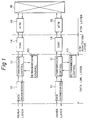
- Figure 1 shows an example of a transmission system wherein retransmission control is carried out in a layer higher than an ATM layer
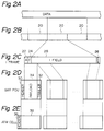
- Figures 2A to 2E show formats of data transmitted between units shown in Fig. 1.
- a data segmentation unit 10 divides data of Fig. 2A, received from a higher layer, into segments 20 having a prescribed length as shown in Fig. 2B.
- a transmission control unit 12 assembles an I (information) frame by adding an A (address) field 22, C (control) field 24, and FCS (frame check sequence) field 26 to I field 28 consisting of each segment, for example, according to X.25 LAPB (link access protocol balanced), as shown in Fig. 2C.
- An SAR (segmentation and reassembly) unit 14 divides I frames into segments having a 44 bytes length and assembles SAR-PDU (protocol data unit) having a 48 bytes length by adding header 30 and trailer 32 to the segment as a payload 34, as shown in Fig. 2D.
- An ATM unit 16 assembles an ATM cell by adding an ATM header 36 having a 5 bytes length to the SAR-PDU as an ATM payload 38, and sends the ATM cell to an ATM network 18.
- a retransmission control unit 40 at a receiver side examines whether a received I frame includes errors, by using the FCS field. According to the X.25 LAPB, the retransmission control unit 40 at the receiver side sends an RR (receive ready) frame including N(R) (receive sequence number) to the retransmission control unit 40 at a transmitter side when one or more I frames, not including errors, are received, and sends an REJ (reject) frame when an I frame, including an error, is received. The retransmission control unit 40 at the transmitter side retransmits the I frame when the RR frame is not received within a prescribed time or when the REJ frame is received.
- the data segmentation unit 10 the transmission control unit 12 and the retransmission control unit 40 belong to a data link layer of the OSI reference model
- the SAR unit 14 belongs to ATM adaptation layer
- the ATM unit 16 belongs to an ATM layer.
- the prescribed length of the I field is small, transmission efficiency is lowered because of a frequent error detection process.
- the prescribed length of the I field is large, the transmission efficiency is lowered as the traffic in the ATM network 18 increases.
- FIG. 3 shows a detailed format of the SAR-PDU shown in Fig. 2D.
- the SAR-header 30 includes an ST (segment type) field, an SN (sequence number) field, and an MID (multiplexing identification) field.
- the SAR-trailer 32 includes an LI (length indicator) field and a CRC (cyclic redundancy check code) field.
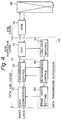
- Figure 4 shows the construction of a transmission system according to an embodiment of the present invention.
- the same reference numerals as used in Fig. 1 are used for constituents that are similar to those in Fig. 1.
- a data transmission supervisor 42 consists of the retransmission control unit 40, a loss rate watching unit 44, and a frame length setting unit 46.
- the loss rate watching unit 44 at a receiver side calculates the rate of lost cells per unit time, from the number of lost cells or cells including errors among cells received in the SAR unit 14 and the number of received cells not including errors.
- the number of lost cells is obtained by watching the SN fields of the ATM cells received in the SAR unit 14, and whether the received cells include errors is determined by using the CRC field of the SAR-trailer 32 in the SAR unit 14.
- the rate of lost cells is fed through the retransmission control unit 40 to the frame length setting unit 46 at the receiver side.
- the frame length setting unit 46 determines the optimum length of the I field in accordance with the rate of lost cells. Namely, if the loss rate is smaller, a longer length is selected, and if the loss rate is larger, a shorter length is selected.
- the frame length setting unit 46 communicates the determined I field length to the data segmentation units 10 of the receiver side and the transmitter side. The communication of the I field length to the transmitter side is carried out through a link between the retransmission control units 40 of the receiver and transmitter sides according to a protocol described later.
- the retransmission control unit 40 performs the above process to attain a frame length control as well as the previously mentioned retransmission process.
- the loss rate watching unit 44 calculates the loss rate as mentioned previously (arrow A), and communicates the loss rate to the retransmission control unit 40 (arrow B).
- the retransmission control unit 40 communicates the loss rate to the frame length setting unit 46 (arrow C).
- the frame length setting unit 46 determines the optimum I field length according to the loss rate, and communicates the I field length to the data segmentation unit 10 (arrow D) and to the retransmission control unit 40 (arrow E).
- the retransmission control unit 40 communicates the I field length through the transmission control unit 12 (arrow F) to a data transmission supervisor 42 at the transmitter side according to a protocol described later.
- the retransmission control unit 40 Upon receiving the I field length from the receiver side (arrow G), the retransmission control unit 40 communicates the I field length to the frame length setting unit 46 (arrow H). The frame length setting unit 46 sets the I field length at the data segmentation unit 10 (arrow I).
- Figure 7 shows a first example of the protocol for communicating the I field length from the data transmission supervisor 42 of the receiver side to that of the transmitter side.
- the data transmission supervisor at the receiver side sends a SABM (set asynchronous balanced mode) command to the transmitter side in order to establish a data link and communicate the I field length data.
- SABM set asynchronous balanced mode
- UA unnumbered acknowledgement
- RR receiver ready
- DISC disconnect
- Figures 8A and 8B show a format of the I frame containing the I field length data.
- the I frame includes one byte of I field as shown in Fig. 8A.
- the I field includes a 3 bit length data field as shown in Fig. 8B.
- the binary code in the length data field corresponds to the length of I field for containing information transmitted from the transmitter side, as shown in Fig. 9.
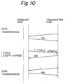
- Figure 10 shows a second example of the protocol for communicating the I field length from the receiver side to the transmitter side.
- the I field length data is transmitted on a special I frame having the same format as a usual I frame for transmitting usual data in a reverse direction, and a data link for transmitting the field length data only is not required.
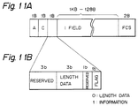
- Figure 11A and Figure 11B show a frame format of the I frame in the second protocol.
- the I frame includes 1 byte information after the C field.
- the 1 byte information includes a 3 bit length data field and 1 bit flag field, as shown in Fig. 11B.
- the binary code in the length field represents the length of I field for containing usual information, according to the correspondence of Fig. 9.
- the flag field is "1”
- the I frame includes the usual I field having a 1 kB to 128 kB length.
- flag field is "0"
- the I frame contains length data in the length data field and does not include the usual I field.
Abstract
Description
- The present invention relates to a method and an apparatus for controlling a length of information frames assembled to perform error recovery control in data transmission that is realized using an ATM (Asynchronous Transfer Mode) network.
- The ATM network provides various types of services having various traffic characteristics in various transmission speeds from high speed to low speed, by segmentating transmission data into cells having a fixed 53 bytes length and by statistically multiplexing the cells. When a congestion of cells occurs because of an increase in traffic in the ATM network, cells can be lost, because the ATM layer does not provide an error recovery procedure. Therefore, to securely transmit burst digital data, an error recovery control should be provided in a data link layer higher than the ATM layer.
- Conventional data link protocols such as an LAPB (link access protocol balanced) may be used to perform the error recovery control, wherein the transmission data are segmentated into frames including error detection codes and the frames are retransmitted if frames are not received in a receiver side or if errors are detected in received frames.
- If the frames are short, a process for error detection is frequently carried out, and therefore, transmission efficiency is lowered, but, if the frames are long, the error detection process is not frequently carried out. However, as the traffic in the ATM network increases, the congestion of cells frequently occurs. Then, if the frames are long, the rate of received frames including errors increases, so that retransmission frequently occurs, and consequently, transmission efficiency is lowered.
- It is an object of the present invention to provide a method and apparatus for adaptively controlling a length of frames in accordance with the congestion condition of cells in an ATM network.
- In accordance with the present invention, there is provided a method of controlling a length of information frames in a data transmission where transmitted data are divided into information frames in a first layer of a hierarical reference model where error recovery control is attained and the information frames are further divided into cells in a second layer lower than the first layer in order to be transmitted on an asynchronous transfer mode network, comprising the steps of detecting a rate of cells lost in the transmission on the asynchronous transfer mode network, in the second layer, determining a length in accordance with the rate detected in the detecting step, in the first layer, and using the length determined in the determining step as the length of the information frames in the first layer.
- In accordance with the present invention there is also provided an apparatus for controlling the length of information frames in a data transmission where transmitted data are divided into the information frames in a first layer of a hierarical reference model where error recovery control is attained and information frames are further divided into cells in a second layer lower than the first layer in order to be transmitted on an asynchronous transfer mode network, comprising means for detecting a rate of cells lost in the transmission on the asynchronous transfer mode network, in the second layer, means for determining a length in accordance with the rate detected by the detecting means, in the first layer, and means for using the length determined by the determining means as the length of the information frames in the first layer.
-
- Figure 1 is a block diagram showing an example of a transmission system wherein retransmission control is carried out in a layer higher than an ATM layer;
- Figures 2A to 2E are diagrams showing formats of data transmitted between units shown in Fig. 1;
- Figure 3 is a diagram showing a detailed format of the SAR-PDU shown in Fig. 2D;
- Figure 4 is a block diagram showing the construction of a transmission system according to an embodiment of the present invention;
- Figure 5 is a block diagram explaining an operation of the data transmission supervisor shown in Fig. 4 at a receiver side;
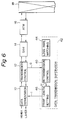
- Figure 6 is a block diagram explaining an operation of the data transmission supervisor at a transmitter side;
- Figure 7 is a diagram showing a first example of the protocol for communicating the length data from the receiver side to the transmitter side;
- Figure 8A and 8B are diagrams showing a format of an I frame containing the length data;
- Figure 9 is a diagram showing correspondence of the length data with the I field length;
- Figure 10 is a diagram showing a second example of the protocol for communicating the length data from the receiver side to the transmitter side; and
- Figures 11A and 11B are diagrams showing a format of the I frame in the second protocol.
- Before describing the preferred embodiments according to the present invention, examples of the related art are given with reference to the accompanying drawings.
- Figure 1 shows an example of a transmission system wherein retransmission control is carried out in a layer higher than an ATM layer, and Figures 2A to 2E show formats of data transmitted between units shown in Fig. 1.
- In a transmitted data flow, shown by arrows indicating a direction to the right in Fig. 1, a
data segmentation unit 10 divides data of Fig. 2A, received from a higher layer, intosegments 20 having a prescribed length as shown in Fig. 2B. Atransmission control unit 12 assembles an I (information) frame by adding an A (address)field 22, C (control)field 24, and FCS (frame check sequence)field 26 to Ifield 28 consisting of each segment, for example, according to X.25 LAPB (link access protocol balanced), as shown in Fig. 2C. An SAR (segmentation and reassembly)unit 14 divides I frames into segments having a 44 bytes length and assembles SAR-PDU (protocol data unit) having a 48 bytes length by addingheader 30 andtrailer 32 to the segment as apayload 34, as shown in Fig. 2D. AnATM unit 16 assembles an ATM cell by adding anATM header 36 having a 5 bytes length to the SAR-PDU as anATM payload 38, and sends the ATM cell to anATM network 18. - In a received data flow shown by arrows indicating a direction to the left in Fig. 1, data are transferred according to a process in reverse order of the aforementioned process.
- A
retransmission control unit 40 at a receiver side examines whether a received I frame includes errors, by using the FCS field. According to the X.25 LAPB, theretransmission control unit 40 at the receiver side sends an RR (receive ready) frame including N(R) (receive sequence number) to theretransmission control unit 40 at a transmitter side when one or more I frames, not including errors, are received, and sends an REJ (reject) frame when an I frame, including an error, is received. Theretransmission control unit 40 at the transmitter side retransmits the I frame when the RR frame is not received within a prescribed time or when the REJ frame is received. - As shown in Fig. 1, the
data segmentation unit 10, thetransmission control unit 12 and theretransmission control unit 40 belong to a data link layer of the OSI reference model, theSAR unit 14 belongs to ATM adaptation layer, and theATM unit 16 belongs to an ATM layer. - As mentioned previously, if the prescribed length of the I field is small, transmission efficiency is lowered because of a frequent error detection process. On the other hand, if the prescribed length of the I field is large, the transmission efficiency is lowered as the traffic in the
ATM network 18 increases. - The preferred embodiments of the present invention will now be described with reference to the accompanying drawings.
- Figure 3 shows a detailed format of the SAR-PDU shown in Fig. 2D. The SAR-
header 30 includes an ST (segment type) field, an SN (sequence number) field, and an MID (multiplexing identification) field. The SAR-trailer 32 includes an LI (length indicator) field and a CRC (cyclic redundancy check code) field. - Figure 4 shows the construction of a transmission system according to an embodiment of the present invention. The same reference numerals as used in Fig. 1 are used for constituents that are similar to those in Fig. 1.
- A
data transmission supervisor 42 consists of theretransmission control unit 40, a lossrate watching unit 44, and a framelength setting unit 46. - The loss
rate watching unit 44 at a receiver side calculates the rate of lost cells per unit time, from the number of lost cells or cells including errors among cells received in theSAR unit 14 and the number of received cells not including errors. The number of lost cells is obtained by watching the SN fields of the ATM cells received in theSAR unit 14, and whether the received cells include errors is determined by using the CRC field of the SAR-trailer 32 in theSAR unit 14. The rate of lost cells is fed through theretransmission control unit 40 to the framelength setting unit 46 at the receiver side. - The frame
length setting unit 46 determines the optimum length of the I field in accordance with the rate of lost cells. Namely, if the loss rate is smaller, a longer length is selected, and if the loss rate is larger, a shorter length is selected. The framelength setting unit 46 communicates the determined I field length to thedata segmentation units 10 of the receiver side and the transmitter side. The communication of the I field length to the transmitter side is carried out through a link between theretransmission control units 40 of the receiver and transmitter sides according to a protocol described later. - The
retransmission control unit 40 performs the above process to attain a frame length control as well as the previously mentioned retransmission process. - An operation of the
data transmission supervisor 42 at the receiver side is described referring to Figure 5. The lossrate watching unit 44 calculates the loss rate as mentioned previously (arrow A), and communicates the loss rate to the retransmission control unit 40 (arrow B). Theretransmission control unit 40 communicates the loss rate to the frame length setting unit 46 (arrow C). The framelength setting unit 46 determines the optimum I field length according to the loss rate, and communicates the I field length to the data segmentation unit 10 (arrow D) and to the retransmission control unit 40 (arrow E). Theretransmission control unit 40 communicates the I field length through the transmission control unit 12 (arrow F) to adata transmission supervisor 42 at the transmitter side according to a protocol described later. - An operation of the
data transmission supervisor 42 at the transmitter side is described referring to Figure 6. Upon receiving the I field length from the receiver side (arrow G), theretransmission control unit 40 communicates the I field length to the frame length setting unit 46 (arrow H). The framelength setting unit 46 sets the I field length at the data segmentation unit 10 (arrow I). - Figure 7 shows a first example of the protocol for communicating the I field length from the
data transmission supervisor 42 of the receiver side to that of the transmitter side. The data transmission supervisor at the receiver side sends a SABM (set asynchronous balanced mode) command to the transmitter side in order to establish a data link and communicate the I field length data. If an UA (unnumbered acknowledgement) response is received from the transmitter side, an I frame containing the I field length data is sent to the transmitter side. If an RR (receive ready) response is received, a DISC (disconnect) command is sent to the transmitter side. After an UA response is received, the data link is released. - Figures 8A and 8B show a format of the I frame containing the I field length data. The I frame includes one byte of I field as shown in Fig. 8A. The I field includes a 3 bit length data field as shown in Fig. 8B. The binary code in the length data field corresponds to the length of I field for containing information transmitted from the transmitter side, as shown in Fig. 9.
- Figure 10 shows a second example of the protocol for communicating the I field length from the receiver side to the transmitter side. In the protocol shown in Fig. 10., the I field length data is transmitted on a special I frame having the same format as a usual I frame for transmitting usual data in a reverse direction, and a data link for transmitting the field length data only is not required. Figure 11A and Figure 11B show a frame format of the I frame in the second protocol. As shown in Fig. 11A, the I frame includes 1 byte information after the C field. The 1 byte information includes a 3 bit length data field and 1 bit flag field, as shown in Fig. 11B. The binary code in the length field represents the length of I field for containing usual information, according to the correspondence of Fig. 9. When the flag field is "1", the I frame includes the usual I field having a 1 kB to 128 kB length. When flag field is "0", the I frame contains length data in the length data field and does not include the usual I field.
- Reference signs in the claims are intended for better understanding and shall not limit the scope.
Claims (6)
- A method of controlling the length of information frames in a data transmission where transmitted data are divided into information frames in a first layer of a hierarical reference model where error recovery control is attained and the information frames are further divided into cells in a second layer lower than the first layer in order to be transmitted on an asynchronous transfer mode network, comprising the steps of:i) detecting the rate of cells lost in the transmission on the asynchronous transfer mode network, in the second layer;ii) determining a length in accordance with the rate detected in step i), in the first layer; andiii) using the length determined in step ii) as the length of the information frames in the first layer.
- A method as claimed in claim 1, wherein the steps i) and ii) are executed in a receiver side and the method further comprises the step ofiv) communicating the determined length to a transmitter side in the first layer.
- A method as claimed in claim 1 or 2, wherein each cell in the second layer includes a sequence number and the step i) includes the substeps of:
monitoring the sequence number of each cell, and
calculating the rate of lost cells from the monitored sequence number. - An apparatus for controlling the length of information frames in a data transmission where transmitted data are divided into information frames in a first layer of a hierarical reference model where error recovery control is attained and the information frames are further divided into cells in a second layer lower than the first layer in order to be transmitted on an asynchronous transfer mode network, comprising
means (44) for detecting a rate of cells lost in the transmission on the asynchronous transfer mode network, in the second layer;
means (46) for determining a length in accordance with the rate detected by the detecting means, in the first layer; and
means (10) for using the length determined by the determining means as the length of the information frames in the first layer. - An apparatus as claimed in claim 4, further comprising
means (42) for communicating the length determined by the determining means at a receiver side to a transmitter side. - An apparatus as claimed in claim 4 or 5, wherein each cell in the second layer includes a sequence number and the detecting means includes
means for monitoring the sequence number of each cell, and
means for calculating the rate of lost cells from the sequence number monitored by the monitoring means.
Applications Claiming Priority (2)
| Application Number | Priority Date | Filing Date | Title |
|---|---|---|---|
| JP204515/91 | 1991-08-15 | ||
| JP20451591A JPH0548638A (en) | 1991-08-15 | 1991-08-15 | End to end congestion coping control processing system in atm network |
Publications (2)
| Publication Number | Publication Date |
|---|---|
| EP0528370A2 true EP0528370A2 (en) | 1993-02-24 |
| EP0528370A3 EP0528370A3 (en) | 1994-11-09 |
Family
ID=16491813
Family Applications (1)
| Application Number | Title | Priority Date | Filing Date |
|---|---|---|---|
| EP9292113880A Withdrawn EP0528370A3 (en) | 1991-08-15 | 1992-08-14 | Frame length control in data transmission using atm network |
Country Status (4)
| Country | Link |
|---|---|
| US (1) | US5535221A (en) |
| EP (1) | EP0528370A3 (en) |
| JP (1) | JPH0548638A (en) |
| CA (1) | CA2075650C (en) |
Cited By (3)
| Publication number | Priority date | Publication date | Assignee | Title |
|---|---|---|---|---|
| EP0844795A2 (en) * | 1996-11-20 | 1998-05-27 | Gpt Limited | Telecommunications access system and equipment |
| EP1337063A2 (en) * | 1998-03-31 | 2003-08-20 | Samsung Electronics Co., Ltd. | Turbo encoding / decoding device and method for processing frame data |
| CN108900831A (en) * | 2018-05-25 | 2018-11-27 | 烽火通信科技股份有限公司 | Flower screen event detecting method and its detection system |
Families Citing this family (23)
| Publication number | Priority date | Publication date | Assignee | Title |
|---|---|---|---|---|
| PT732028E (en) * | 1993-11-30 | 2002-07-31 | Gen Electric | DATA WORD INDICATOR IN A SYSTEM FOR MOUNTING OF TRANSPORT DATA PACKAGES |
| US5638367A (en) * | 1995-07-07 | 1997-06-10 | Sun Microsystems, Inc. | Apparatus and method for data packing through addition |
| US5790544A (en) * | 1996-03-25 | 1998-08-04 | International Business Machines Corporation | ATM cell-to-frame reassembly method and apparatus for overrun avoidance |
| US6728921B1 (en) | 1996-05-31 | 2004-04-27 | Nortel Networks Limited | Cell based data transmission method |
| GB2313748B (en) * | 1996-05-31 | 2000-12-20 | Northern Telecom Ltd | Cell based data transmission method |
| US5878028A (en) * | 1996-06-06 | 1999-03-02 | Advanced Micro Devices, Inc. | Data structure to support multiple transmit packets for high performance |
| WO1998029987A1 (en) * | 1996-12-26 | 1998-07-09 | Ntt Mobile Communications Network Inc. | Data transmitting method |
| JP2871650B2 (en) * | 1997-04-17 | 1999-03-17 | 日本電気株式会社 | Data transmission system |
| US6229821B1 (en) * | 1997-04-22 | 2001-05-08 | At&T Corp. | Serial data transmission of variable length mini packets using statistical multiplexing |
| US5991912A (en) * | 1997-05-15 | 1999-11-23 | Next Level Communications | Digital video transport error handling in cell based communications systems |
| US6931009B1 (en) * | 1997-07-15 | 2005-08-16 | Viasat, Inc. | Frame format and frame assembling/disassembling method for the frame format |
| US7570645B2 (en) * | 2000-01-18 | 2009-08-04 | Viasat, Inc. | Frame format and frame assembling/disassembling method for the frame format |
| US6819658B1 (en) | 1997-07-15 | 2004-11-16 | Comsat Corporation | Method and apparatus for segmentation, reassembly and inverse multiplexing of packets and ATM cells over satellite/wireless networks |
| AU8389098A (en) * | 1997-07-15 | 1999-02-10 | Comsat Corporation | Method and apparatus for improving asynchronous transfer mode operation over noisy, high speed wireless links |
| JP3500565B2 (en) * | 1998-07-27 | 2004-02-23 | 富士通株式会社 | Message division communication method and communication system |
| US7215650B1 (en) | 1999-08-16 | 2007-05-08 | Viasat, Inc. | Adaptive data rate control for narrowcast networks |
| US7230908B2 (en) * | 2000-07-24 | 2007-06-12 | Viasat, Inc. | Dynamic link assignment in a communication system |
| US7965729B2 (en) * | 2001-05-23 | 2011-06-21 | Polytechnic University | Transferring data such as files |
| US7570654B2 (en) * | 2003-12-22 | 2009-08-04 | Intel Corporation | Switching device utilizing requests indicating cumulative amount of data |
| US7623524B2 (en) * | 2003-12-22 | 2009-11-24 | Intel Corporation | Scheduling system utilizing pointer perturbation mechanism to improve efficiency |
| US7324541B2 (en) * | 2003-12-22 | 2008-01-29 | Intel Corporation | Switching device utilizing internal priority assignments |
| US20050207436A1 (en) * | 2004-03-18 | 2005-09-22 | Anujan Varma | Switching device based on aggregation of packets |
| US20080159145A1 (en) * | 2006-12-29 | 2008-07-03 | Raman Muthukrishnan | Weighted bandwidth switching device |
Citations (4)
| Publication number | Priority date | Publication date | Assignee | Title |
|---|---|---|---|---|
| EP0254047A2 (en) * | 1986-07-21 | 1988-01-27 | International Business Machines Corporation | Packet length traffic control in a local area network |
| EP0269202A2 (en) * | 1986-11-28 | 1988-06-01 | Gec-Marconi Limited | A communication system |
| EP0355797A2 (en) * | 1988-08-26 | 1990-02-28 | Hitachi, Ltd. | Signalling apparatus for use in an ATM switching system |
| EP0430571B1 (en) * | 1989-11-30 | 1996-03-06 | AT&T Corp. | Dynamic window sizing in a data network |
Family Cites Families (12)
| Publication number | Priority date | Publication date | Assignee | Title |
|---|---|---|---|---|
| JP2667868B2 (en) * | 1988-04-06 | 1997-10-27 | 株式会社日立製作所 | Cell switching system |
| US5258752A (en) * | 1988-11-25 | 1993-11-02 | Sumitomo Electric Industries, Ltd. | Broad band digital exchange |
| JPH02151152A (en) * | 1988-12-02 | 1990-06-11 | Nippon Telegr & Teleph Corp <Ntt> | Frame transmission method |
| US5214642A (en) * | 1989-02-21 | 1993-05-25 | Hitachi, Ltd. | ATM switching system and adaptation processing apparatus |
| FR2655223B1 (en) * | 1989-11-27 | 1992-02-07 | Cit Alcatel | METHOD OF MANAGING FLOWS IN A BROADBAND BROADBAND DIGITAL TELECOMMUNICATION NETWORK, AND NETWORK FOR CARRYING OUT SAID METHOD. |
| JPH04100342A (en) * | 1990-08-20 | 1992-04-02 | Toshiba Corp | Traffic control system |
| JP3241716B2 (en) * | 1990-08-31 | 2001-12-25 | 株式会社東芝 | ATM exchange method |
| FR2669798B1 (en) * | 1990-11-23 | 1994-09-16 | Lmt Radio Professionelle | DEVICE FOR TRANSMITTING SYNCHRONOUS INFORMATION OVER AN ASYNCHRONOUS NETWORK, ESPECIALLY AN ATM NETWORK. |
| US5124978A (en) * | 1990-11-26 | 1992-06-23 | Bell Communications Research, Inc. | Grouping network based non-buffer statistical multiplexor |
| DE69129851T2 (en) * | 1991-09-13 | 1999-03-25 | Ibm | Configurable gigabit / s switch adapter |
| US5313454A (en) * | 1992-04-01 | 1994-05-17 | Stratacom, Inc. | Congestion control for cell networks |
| US5311513A (en) * | 1992-09-10 | 1994-05-10 | International Business Machines Corp. | Rate-based congestion control in packet communications networks |
-
1991
- 1991-08-15 JP JP20451591A patent/JPH0548638A/en active Pending
-
1992
- 1992-08-10 CA CA002075650A patent/CA2075650C/en not_active Expired - Fee Related
- 1992-08-13 US US07/928,709 patent/US5535221A/en not_active Expired - Lifetime
- 1992-08-14 EP EP9292113880A patent/EP0528370A3/en not_active Withdrawn
Patent Citations (4)
| Publication number | Priority date | Publication date | Assignee | Title |
|---|---|---|---|---|
| EP0254047A2 (en) * | 1986-07-21 | 1988-01-27 | International Business Machines Corporation | Packet length traffic control in a local area network |
| EP0269202A2 (en) * | 1986-11-28 | 1988-06-01 | Gec-Marconi Limited | A communication system |
| EP0355797A2 (en) * | 1988-08-26 | 1990-02-28 | Hitachi, Ltd. | Signalling apparatus for use in an ATM switching system |
| EP0430571B1 (en) * | 1989-11-30 | 1996-03-06 | AT&T Corp. | Dynamic window sizing in a data network |
Cited By (7)
| Publication number | Priority date | Publication date | Assignee | Title |
|---|---|---|---|---|
| EP0844795A2 (en) * | 1996-11-20 | 1998-05-27 | Gpt Limited | Telecommunications access system and equipment |
| EP0844795A3 (en) * | 1996-11-20 | 2000-03-08 | Marconi Communications Limited | Telecommunications access system and equipment |
| US6426964B1 (en) | 1996-11-20 | 2002-07-30 | Marconi Communications Limited | Telecommunications access systems and equipment |
| EP1337063A2 (en) * | 1998-03-31 | 2003-08-20 | Samsung Electronics Co., Ltd. | Turbo encoding / decoding device and method for processing frame data |
| EP1337063A3 (en) * | 1998-03-31 | 2003-08-27 | Samsung Electronics Co., Ltd. | Turbo encoding / decoding device and method for processing frame data |
| US6920602B1 (en) | 1998-03-31 | 2005-07-19 | Samsung Electronics Co., Ltd. | Turbo encoding/decoding device and method for processing frame data according to QoS |
| CN108900831A (en) * | 2018-05-25 | 2018-11-27 | 烽火通信科技股份有限公司 | Flower screen event detecting method and its detection system |
Also Published As
| Publication number | Publication date |
|---|---|
| EP0528370A3 (en) | 1994-11-09 |
| JPH0548638A (en) | 1993-02-26 |
| CA2075650C (en) | 1998-07-28 |
| CA2075650A1 (en) | 1993-02-16 |
| US5535221A (en) | 1996-07-09 |
Similar Documents
| Publication | Publication Date | Title |
|---|---|---|
| US5535221A (en) | Frame length control in data transmission using ATM network | |
| US6307867B1 (en) | Data transmission over a communications link with variable transmission rates | |
| US6075798A (en) | Extended header for use in ATM adaptation layer type 2 packets | |
| EP1943800B1 (en) | Method for receiving and managing a downlink radio link control data block in an egprs mobile electronic communication device | |
| EP2824887B1 (en) | Apparatus and method for transmitting variable-length data according to a radio link protocol in a mobile communication system | |
| US7359403B1 (en) | Data segmentation method in a telecommunications system | |
| RU2430481C2 (en) | Method and apparatus for signalling packet segmentation and linking in communication system | |
| US6161207A (en) | Communications unit and method of communicating having efficient packet acknowledgement | |
| US5481562A (en) | Multi-mode modem and data transmission method | |
| US6141784A (en) | Method and system in a data communications system for the retransmission of only an incorrectly transmitted portion of a data packet | |
| AU723092B2 (en) | Minicell sequence number count | |
| US6959406B2 (en) | Block error ratio measurements | |
| EP1073228B1 (en) | Data link protocol for wireless systems | |
| AU2295500A (en) | Flow control method in a telecommunications system | |
| EP1198917B1 (en) | Method and system for data reception acknowledgement | |
| WO2002043403A2 (en) | Enhanced data link layer selective reject mechanism in noisy wireless environment | |
| US7330902B1 (en) | Header compression | |
| CN101162973A (en) | Method and devices for digital data transfer | |
| US5712860A (en) | Methods and system for using multi-block bursts in half duplex subscriber unit transmissions | |
| GB2266641A (en) | Digital mobile telephone control system | |
| US6922401B1 (en) | Arrangement for optimizing the data transmission over a bidirectional radio channel | |
| US6965565B1 (en) | System and method for communicating an event status across a data channel | |
| JPH03131143A (en) | Method for setting packet length | |
| EP1162776A1 (en) | Method of measuring the block error rate | |
| Cho et al. | Performance of hybrid II ARQ schemes using punctured RS code for wireless ATM |
Legal Events
| Date | Code | Title | Description |
|---|---|---|---|
| PUAI | Public reference made under article 153(3) epc to a published international application that has entered the european phase |
Free format text: ORIGINAL CODE: 0009012 |
|
| AK | Designated contracting states |
Kind code of ref document: A2 Designated state(s): DE FR GB |
|
| PUAL | Search report despatched |
Free format text: ORIGINAL CODE: 0009013 |
|
| AK | Designated contracting states |
Kind code of ref document: A3 Designated state(s): DE FR GB |
|
| 17P | Request for examination filed |
Effective date: 19950208 |
|
| 17Q | First examination report despatched |
Effective date: 19990514 |
|
| STAA | Information on the status of an ep patent application or granted ep patent |
Free format text: STATUS: THE APPLICATION IS DEEMED TO BE WITHDRAWN |
|
| 18D | Application deemed to be withdrawn |
Effective date: 20010316 |