EP0520741A1 - Image compression associated with camera shake correction - Google Patents
Image compression associated with camera shake correction Download PDFInfo
- Publication number
- EP0520741A1 EP0520741A1 EP19920305754 EP92305754A EP0520741A1 EP 0520741 A1 EP0520741 A1 EP 0520741A1 EP 19920305754 EP19920305754 EP 19920305754 EP 92305754 A EP92305754 A EP 92305754A EP 0520741 A1 EP0520741 A1 EP 0520741A1
- Authority
- EP
- European Patent Office
- Prior art keywords
- image
- image signal
- moving vector
- memory
- compression
- Prior art date
- Legal status (The legal status is an assumption and is not a legal conclusion. Google has not performed a legal analysis and makes no representation as to the accuracy of the status listed.)
- Granted
Links
Images


Classifications
-
- H—ELECTRICITY
- H04—ELECTRIC COMMUNICATION TECHNIQUE
- H04N—PICTORIAL COMMUNICATION, e.g. TELEVISION
- H04N5/00—Details of television systems
- H04N5/76—Television signal recording
- H04N5/765—Interface circuits between an apparatus for recording and another apparatus
- H04N5/77—Interface circuits between an apparatus for recording and another apparatus between a recording apparatus and a television camera
- H04N5/772—Interface circuits between an apparatus for recording and another apparatus between a recording apparatus and a television camera the recording apparatus and the television camera being placed in the same enclosure
-
- H—ELECTRICITY
- H04—ELECTRIC COMMUNICATION TECHNIQUE
- H04N—PICTORIAL COMMUNICATION, e.g. TELEVISION
- H04N19/00—Methods or arrangements for coding, decoding, compressing or decompressing digital video signals
- H04N19/50—Methods or arrangements for coding, decoding, compressing or decompressing digital video signals using predictive coding
- H04N19/503—Methods or arrangements for coding, decoding, compressing or decompressing digital video signals using predictive coding involving temporal prediction
- H04N19/51—Motion estimation or motion compensation
- H04N19/527—Global motion vector estimation
-
- H—ELECTRICITY
- H04—ELECTRIC COMMUNICATION TECHNIQUE
- H04N—PICTORIAL COMMUNICATION, e.g. TELEVISION
- H04N23/00—Cameras or camera modules comprising electronic image sensors; Control thereof
- H04N23/60—Control of cameras or camera modules
- H04N23/68—Control of cameras or camera modules for stable pick-up of the scene, e.g. compensating for camera body vibrations
- H04N23/681—Motion detection
- H04N23/6812—Motion detection based on additional sensors, e.g. acceleration sensors
-
- H—ELECTRICITY
- H04—ELECTRIC COMMUNICATION TECHNIQUE
- H04N—PICTORIAL COMMUNICATION, e.g. TELEVISION
- H04N23/00—Cameras or camera modules comprising electronic image sensors; Control thereof
- H04N23/60—Control of cameras or camera modules
- H04N23/68—Control of cameras or camera modules for stable pick-up of the scene, e.g. compensating for camera body vibrations
- H04N23/681—Motion detection
- H04N23/6815—Motion detection by distinguishing pan or tilt from motion
-
- H—ELECTRICITY
- H04—ELECTRIC COMMUNICATION TECHNIQUE
- H04N—PICTORIAL COMMUNICATION, e.g. TELEVISION
- H04N23/00—Cameras or camera modules comprising electronic image sensors; Control thereof
- H04N23/60—Control of cameras or camera modules
- H04N23/68—Control of cameras or camera modules for stable pick-up of the scene, e.g. compensating for camera body vibrations
- H04N23/682—Vibration or motion blur correction
- H04N23/683—Vibration or motion blur correction performed by a processor, e.g. controlling the readout of an image memory
-
- H—ELECTRICITY
- H04—ELECTRIC COMMUNICATION TECHNIQUE
- H04N—PICTORIAL COMMUNICATION, e.g. TELEVISION
- H04N5/00—Details of television systems
- H04N5/76—Television signal recording
- H04N5/91—Television signal processing therefor
- H04N5/92—Transformation of the television signal for recording, e.g. modulation, frequency changing; Inverse transformation for playback
- H04N5/926—Transformation of the television signal for recording, e.g. modulation, frequency changing; Inverse transformation for playback by pulse code modulation
- H04N5/9261—Transformation of the television signal for recording, e.g. modulation, frequency changing; Inverse transformation for playback by pulse code modulation involving data reduction
- H04N5/9264—Transformation of the television signal for recording, e.g. modulation, frequency changing; Inverse transformation for playback by pulse code modulation involving data reduction using transform coding
Abstract
Description
- This invention relates to a signal processing device, and more particularly, to compression processing of image signals.
- Recently, so-called digital VCR's (video cassette recorders) are being considered in which digital signal processing of image signals of so-called VCR's is performed which use magnetic tapes having a width of 1/2 inches or 8 millimeters for recording moving-image signals.
- The digital VCR performs various kinds of image processing using correlation between images in time. One example of such processing is frame correlation image compression processing which uses correlation between images in the direction of time base.
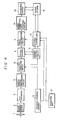
- FIG. 5 is a diagram showing the principle of the frame correlation image compression processing.
- In FIG. 5, there are shown a picture frame n, and a picture frame n + 1 immediately after the picture frame n in the direction of time base indicated by arrow t. FIG. 5 illustrates a case in which a coded pixel (picture element) Pn+1 of the next picture frame n + 1 is subjected to interframe encoding based on a target pixel Pn of the picture frame n.
- The processing is based on a premise (an assumption) that there is strong correlation between immediately successive picture frames of a moving-image signal, and basically, pixel data at the same position in adjacent frames have substantially the same value.
- If encoding is performed according to simple interframe prediction, only the difference between the pixels Pn and Pn+1, which is the variance in the image deviation from the above-described premise, is encoded. Hence, it is possible to reduce the amount of data by a method, such as nonlinear quantization or the like, which is similar to one-dimensional DPCM (differential pulse-code modulation).
- Such a method compresses the amount of data so that, for example, only transmission of information of "the same as the preceding frame" suffices in the case of a perfectly still picture on the assumption that correlation increases as the values of pixel data are closer between frames.
- However, when correlation between images is low, data corresponding to the predicted error from a predicted correlation value must be transmitted. Hence, when the entire picture frame has much movement, there is a possibility of temporarily generating of a large amount of data.
- Accordingly, in the case of a portable image recording apparatus provided with the above-described digital signal processing system, various kinds of image processing using time-base correlation between images cannot be effectively performed owing to displacement of picture frames caused by unintended hand movement.
- The present invention has been made in consideration of the problems of the prior art.
- It is an object of the present invention to provide a signal processing device which can efficiently perform various kinds of image processing using time-base correlation of images.
- This object is accomplished, according to one aspect of the present invention, by a signal processing device comprising an image displacement corrector that removes image displacement in an image signal, and a compression unit that compresses the image signal output from the image displacement corrector.
- Other objects and advantages of the invention will become apparent from the following detailed description taken in conjunction with the accompanying drawings.
-
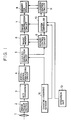
- FIG. 1 is a block diagram of an image pickup apparatus according to a first embodiment of the present invention;
- FIGS. 2(a) and 2(b) are diagrams illustrating correction of shaking according to the first embodiment;
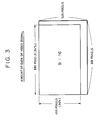
- FIG. 3 is a diagram illustrating a picture surface for displaying image information according to the first embodiment;
- FIG. 4 is a block diagram of an image pickup apparatus according to a second embodiment of the present invention; and
- FIG. 5 is a schematic diagram illustrating image compression according to a time-base correlation method.
- A signal processing device illustrating a signal processing unit provided within an image pickup apparatus including an image pickup means will now be explained.
- An image pickup apparatus according to a first embodiment of the present invention will be explained in detail with reference to FIGS. 1 - 3.
- FIG. 1 is a block diagram of the image pickup apparatus of the present embodiment. FIGS. 2(a) and 2(b) are diagrams illustrating shaking correction. FIG. 3 is a diagram illustrating a picture surface for displaying image information.
- In FIG. 1, there are shown an imaging optical system 1, and a solid-state
image pickup device 2, such as a CCD (charge-coupled device) or the like. Incident light of a photographed image from the imaging optical system 1 is imaged onto the solid-stateimage pickup device 2, and is subjected to photoelectric conversion, whereby an image signal is obtained. - An A/
D converter 3 converts the image signal into a digital image signal. A digital signal processing circuit (DSP circuit) 4 performs well-known video camera signal processing, such as γ-conversion, knee-characteristic processing, color balance adjustment or the like. - A shaking
correction circuit 5 corrects shaking of the picture surface. Animage memory 6 temporarily stores an image signal for at least one field. There are also shown animage compression circuit 7, and amemory 8 for storing image signals. Amemory control circuit 9 controls a reading operation of stored image signals. Amicrocomputer 10 for controlling the system (hereinafter termed a system controller) controls theimage compression circuit 7, thememory control circuit 9, an address control circuit 11 (to be described below) and the like. - The
address control circuit 11 controls storing of image signals in thememory 8. A shaking/panning sensor 12 detects panning which is frequently used in a camera work. There is also shown anoperation key 13. - An explanation will now be provided of the signal processing operations until storage of an image by the image pickup apparatus having the above-described configuration.
- A photographed optical image from the imaging optical system 1 is focused onto the
image pickup device 2. The focused optical image is converted into an electrical image signal by theimage pickup device 2. The image sigal is converted into a digital image signal by the A/D converter 3, and is input to theDSP circuit 4, in which predetermined signal processing is performed. The image signal output from theDSP circuit 4 is input to the shakingcorrection circuit 5, in which shaking of the photographed image is corrected. - The operation of the shaking
correction circuit 5 will be more specifically explained with reference to FIGS. 2(a) and 2(b). - As shown in FIG. 2(a), a photographed picture frame having a size of H₀ x V₀ which has allowance both in the horizontal and vertical directions relative to a substantially effective picture frame having a size of h x v (horizontal width x vertical width) is set, and is first stored in the
image memory 6. - As shown in FIG. 2(b), cutting of an effective picture frame so as to cancel shaking of an image is realized by controlling the setting of a memory address. That is, the shaking
correction circuit 5 includes a circuit for detecting a moving vector of an image signal, and detects a moving vector corresponding to shaking of the picture frame generated by unintended hand movement. - In the example shown in FIG. 2(b), movement from point A to point B between adjacent frames is detected, and a moving vector v is input to the
memory control circuit 9. Thememory control circuit 9 changes the read address so as to cancel the influence of the vector v. - If it is assumed that point Pn to start reading of image data at the upper left position of picture frame n is

and the moving vector v is
point Pn+1 to start reading of data on picture frame n + 1 is set as
- By thus controlling the memory address, an image signal in which shaking of the picture frame due to unintended hand movement is removed is obtained from the
image memory 6. - In the stabilized image signal obtained as described above, correlation in the direction of time base is high. The above-described image signal is subjected to data compression processing including time-base correlation processing by the
image compression circuit 7 to reduce the amount of image data, and is then stored in the large-capacity solid-state memory 8. - By appropriately combining the above-described interframe correlation processing using temporal correlation between images, moving-vector compensation for reducing deterioration in picture quality in the interframe correlation processing, both-side predictive interframe compression in which interframe compression is performed for time periods before and after (past and future) the present time on time base, and the like, it is possible to reduce the amount of data of a digital image signal to about a fraction of a few tenths to a few hundredths of the original amount.
- More specifically, according to the JPEG (Joint Photographic Expert Group) method in which encoding is performed by DCT (discrete cosine transform) in units of a block comprising (8 x 8) pixels, or the so-called MPEG-I which is an algorithm proposed by the MPEG (Moving Picture Expert Group), standard picture quality substantially equivalent to that of a so-called 1/2-inch VCR can be obtained.
- The above-described compression and storage processing is performed by operating the
system controller 10 and theaddress control circuit 11 controlled by thesystem controller 10 through theoperation key 13. - By further adding the shaking/panning
sensor 12 in which the movement of the main body of the camera is detected by external sensors, shaking correction and image compression processing can be more efficiently performed. The shaking/panningsensor 12 comprises a plurality of one-dimensional sensors, such as accelerometers or the like, which constitute necessary detecting axes. For example, when panning which is frequently used in a camera work is detected, panning information (direction, speed, timing and the like) is transmitted from the one-dimensional sensor in the horizontal direction of the shaking/panningsensor 12 to the shakingcorrection circuit 5 and thesystem controller 10. - The shaking
correction circuit 5 which has received the panning information can prevent unnatural processing at the start and end of panning by interrupting correction of the panning direction during a panning operation. - Correlation processing in the horizontal direction can be properly executed according to the panning information transmitted to the
compression circuit 7 via thesystem controller 10, whereby compression processing is optimized. - FIG. 3 illustrates a picture surface for displaying image information.
- In the present embodiment, based on a TV signal of the NTSC system (525 scanning lines), a TV signal having an aspect ratio (9:16) of the image which is close to that of a movie is provided as an input signal. If the effective ratio of the picture surface is assumed to be 94 % both in the vertical and horizontal directions, information of (495 x 880) pixels for 30 picture frames is generated per second, and is supplied to the A/
D converter 3. - The composite image signal input to the A/
D converter 3 is converted into a digital signal, and is subjected to video signal processing of components (for example, Y:(R - Y):(B - Y) = 4:2:2) by theDSP circuit 4 whenever necessary. If luminance (Y) and color difference are quantized in 8 bits with a sampling rate of 1/2, information of about 700 G (giga) bits is obtained per hour. - If a stereo sound signal is digitized at 48 kHz (kilohertz)/16 bits, information of about 5.5 G bits per hour is obtained. If the above-described compression processing is performed for these signals, information of about 4 G bits is obtained for the entire AV (audio-visual) signal.
- Next, an explanation will be provided of an image pickup apparatus according to a second embodiment of the present invention with reference to FIG. 4.
- FIG. 4 is a block diagram of the image pickup apparatus of the second present embodiment. In FIG. 4, the same components as in FIG. 1 are indicated by the same reference numerals, and explanation thereof will be omitted.
- In FIG. 4, an error correcting
code adding circuit 14 corrects erroneous codes in a digital image signal output from theimage compression circuit 7. Arecording system 15 uses media, such as magnetooptical or other disks, digital VCR tapes or the like. Aservo system 16 mechanically controls therecording system 15. - That is, in the second embodiment, an image pickup apparatus which does not employ a solid-state memory is used, the same components as in the first embodiment are used except the above-described three components are added, and the same image signal processing as in the first embodiment is performed.
- As explained above in detail, since the signal processing device of the present invention performs time-base correlation processing of image data compression after removing shaking in an image signal and corelation between images is increased, it is possible to increase efficiency in data compression.
- More particularly, the present invention is expected to greatly remove the influence of hand movement likely to be produced when a small portable image pickup apparatus is used.
- By having a configuration of processing photographed information in the form of digital signals and recording the signals whenever necessary, the present invention can also prevent a reduction in the quality of information and reliability during a retrieving or copying operation.
- Various changes and modifications may be made without departing from the spirit and scope of the invention.
- For example, although in the above-described embodiments, the moving vector of an image signal is detected between adjacent frames, the moving vector of an image signal may be detected between adjacent fields.
- In other words, the foregoing description of the embodiments has been given for illustrative purposes only and is not to be construed as imposing any limitation in every respect.
- The scope of the invention is, therefore, to be determined solely by the following claims and not limited by the text of the specification and alterations that may be made within the scope of the claims fall within the true spirit and scope of the invention.
Claims (16)
- A signal processing device, comprising:
image displacement correction means for removing an image displacement from an image signal; and
compression means for compressing the image signal output from said image displacement correction means. - A device according to Claim 1, wherein the operation of said image displacement correction means is controlled in accordance with an output of an external sensor.
- A device according to Claim 2, wherein said image displacement correction means further comprises moving vector detection means for detecting a moving vector of the image signal.
- A device according to Claim 1, wherein said compression means performs compression by correlating images in time.
- A device according to Claim 4, wherein said compression means includes encoding means for encoding in units of blocks, each comprising two-dimensional arrangement of picture elements.
- A signal processing device, comprising:
image pickup means for converting an optical image into an image signal;
moving vector detection means for detecting a moving vector of the image signal obtained by said image pickup means;
memory means for storing said image signal;
memory control means for reading the image signal by changing an address of said memory means in accordance with the moving vector detected by said moving vector detection means; and
compression means for compressing the image signal read from said memory means by said memory control means. - A device according to Claim 6, wherein said moving vector detection means obtains the moving vector by comparing two frames of the image signal.
- A device according to Claim 6, wherein said memory means stores an image signal for at least a field.
- A device according to Claim 6, wherein said moving vector detection means obtains the moving vector by comparing two fields of the image signal.
- A device according to Claim 6, wherein said compression means performs compression by correlation of images in time.
- A device according to Claim 10, wherein said compression means includes encoding means for encoding in units of blocks, each comprising a two-dimensional arrangement of picture elements.
- A device according to Claim 6, further comprising a sensor for detecting movement of the entire device.
- A device according to Claim 12, wherein said memory control means is controlled in accordance with an output of said sensor.
- A method for processing an image signal comprising the steps of:
correcting an image signal by removing the displacement from the image signal; and
compressing the corrected image signal. - A method for processing an image signal comprising the steps of:
converting an optical image into an image signal;
detecting a moving vector or the image signal;
storing the image signal in a memory;
reading the image signal from the memory by changing an address of the memory according to the detected moving vector; and
compressing the image signal read from the memory. - A method or apparatus for processing video image data in which the data is compressed on the basis of correlation of the image with itself over time,
characterised in that
movement of the image over time is detected and is taken into account in correlating the image with itself over time.
Applications Claiming Priority (2)
| Application Number | Priority Date | Filing Date | Title |
|---|---|---|---|
| JP15162991A JP3227173B2 (en) | 1991-06-24 | 1991-06-24 | Imaging device and method thereof |
| JP151629/91 | 1991-06-24 |
Publications (2)
| Publication Number | Publication Date |
|---|---|
| EP0520741A1 true EP0520741A1 (en) | 1992-12-30 |
| EP0520741B1 EP0520741B1 (en) | 1998-04-29 |
Family
ID=15522721
Family Applications (1)
| Application Number | Title | Priority Date | Filing Date |
|---|---|---|---|
| EP19920305754 Expired - Lifetime EP0520741B1 (en) | 1991-06-24 | 1992-06-23 | Image compression associated with camera shake correction |
Country Status (4)
| Country | Link |
|---|---|
| US (1) | US7218675B1 (en) |
| EP (1) | EP0520741B1 (en) |
| JP (1) | JP3227173B2 (en) |
| DE (1) | DE69225273T2 (en) |
Cited By (7)
| Publication number | Priority date | Publication date | Assignee | Title |
|---|---|---|---|---|
| EP0557007A2 (en) * | 1992-02-15 | 1993-08-25 | Sony Corporation | Picture processing apparatus |
| EP0831644A2 (en) * | 1996-09-20 | 1998-03-25 | Sony Corporation | Image shake discriminator and stabilizer |
| EP1083742A2 (en) | 1999-09-10 | 2001-03-14 | Sony Corporation | Image pickup apparatus and methods |
| WO2012164048A3 (en) * | 2011-05-31 | 2013-03-21 | Skype | Video stabilisation |
| US8723966B2 (en) | 2011-09-26 | 2014-05-13 | Skype | Video stabilization |
| EP3136726A1 (en) * | 2015-08-27 | 2017-03-01 | Axis AB | Method of pre-processing digital images, and digital image pre-processing system |
| US9762799B2 (en) | 2011-10-14 | 2017-09-12 | Skype | Received video stabilization |
Families Citing this family (14)
| Publication number | Priority date | Publication date | Assignee | Title |
|---|---|---|---|---|
| JP2000050151A (en) * | 1998-07-28 | 2000-02-18 | Olympus Optical Co Ltd | Image pickup device |
| JP3636011B2 (en) * | 1999-12-03 | 2005-04-06 | 日本電気株式会社 | Method and apparatus for correcting photographic image data in portable videophone device |
| US7554578B2 (en) * | 2000-07-11 | 2009-06-30 | Phase One A/S | Digital camera with integrated accelerometers |
| US20020193157A1 (en) * | 2001-06-18 | 2002-12-19 | Canon Kabushiki Kaisha | Computer device for implementing a trading card game and control method therefor, program executed by computer device, controller, system, and game cards |
| US7646891B2 (en) * | 2002-12-26 | 2010-01-12 | Mitshubishi Denki Kabushiki Kaisha | Image processor |
| US20050213662A1 (en) * | 2004-03-29 | 2005-09-29 | James Owens | Method of compression and digital imaging device employing compression algorithm |
| US7705884B2 (en) * | 2004-07-21 | 2010-04-27 | Zoran Corporation | Processing of video data to compensate for unintended camera motion between acquired image frames |
| TWI260918B (en) * | 2005-05-30 | 2006-08-21 | Pixart Imaging Inc | Pixel compensation method for an image sensor |
| JP2007067694A (en) * | 2005-08-30 | 2007-03-15 | Mitsubishi Electric Corp | Apparatus and method for encoding image, camera, and portable terminal equipment |
| JP5159189B2 (en) * | 2007-06-29 | 2013-03-06 | キヤノン株式会社 | Image processing apparatus, imaging apparatus, image processing method, and program |
| US8150211B2 (en) * | 2008-03-12 | 2012-04-03 | Intel Corporation | Identifying patterns in data |
| DE102009058597B4 (en) * | 2009-12-17 | 2012-04-19 | Siemens Aktiengesellschaft | Image recording system for recording and transmitting digital video images, image data processing system for receiving and processing digital image data, image stabilization system and method for generating low-blur digital video images |
| CN103957351B (en) * | 2014-04-21 | 2017-12-15 | 深圳市视晶无线技术有限公司 | A kind of three-dimensional camera shooting system and its image debounce processing method |
| US10757350B2 (en) * | 2015-07-31 | 2020-08-25 | Sony Semiconductor Solutions Corporation | Solid-state image pickup device and electronic apparatus |
Citations (3)
| Publication number | Priority date | Publication date | Assignee | Title |
|---|---|---|---|---|
| US4769826A (en) * | 1985-01-16 | 1988-09-06 | Mitsubishi Denki Kabushiki Kaisha | Video encoding apparatus |
| WO1990000334A1 (en) * | 1988-07-01 | 1990-01-11 | Plessey Overseas Limited | Improvements in or relating to image stabilisation |
| US5032927A (en) * | 1988-03-01 | 1991-07-16 | Fuji Photo Film Co., Ltd. | Image signal recording apparatus capable of recording compressed image data together with audio data |
Family Cites Families (44)
| Publication number | Priority date | Publication date | Assignee | Title |
|---|---|---|---|---|
| US4460923A (en) * | 1981-06-01 | 1984-07-17 | Nippon Electric Co., Ltd. | Predictive coding system for television signals |
| US4670851A (en) * | 1984-01-09 | 1987-06-02 | Mitsubishi Denki Kabushiki Kaisha | Vector quantizer |
| JPS60163594A (en) | 1984-02-06 | 1985-08-26 | Hitachi Ltd | Estimation system of motion |
| JPS60189388A (en) * | 1984-03-09 | 1985-09-26 | Fujitsu Ltd | Moving compensation encoder |
| JPS61200789A (en) * | 1985-03-04 | 1986-09-05 | Kokusai Denshin Denwa Co Ltd <Kdd> | System for detecting dynamic vector of object on picture plane |
| IL75728A (en) * | 1985-07-05 | 1989-06-30 | Elbit Computers Ltd | Image converter system |
| JPS6278979A (en) * | 1985-10-02 | 1987-04-11 | Toshiba Corp | Picture processor |
| JPH01109970A (en) | 1987-10-23 | 1989-04-26 | Matsushita Electric Ind Co Ltd | Moving picture fluctuation elimination device |
| JPH01125068A (en) | 1987-11-09 | 1989-05-17 | Matsushita Electric Ind Co Ltd | Blur correcting device |
| JPH01174076A (en) | 1987-12-28 | 1989-07-10 | Hitachi Ltd | Photographing device |
| JP2542662B2 (en) | 1988-01-28 | 1996-10-09 | 富士通株式会社 | Image signal communication method and image signal communication system |
| JP2527210B2 (en) | 1988-03-08 | 1996-08-21 | 富士写真フイルム株式会社 | Image signal recording device |
| US5012270A (en) * | 1988-03-10 | 1991-04-30 | Canon Kabushiki Kaisha | Image shake detecting device |
| JPH01241991A (en) | 1988-03-24 | 1989-09-26 | Nec Corp | Coder for moving image signal |
| JP2693516B2 (en) | 1988-09-14 | 1997-12-24 | 日本放送協会 | Image motion detector |
| JPH02171093A (en) | 1988-12-23 | 1990-07-02 | Nec Corp | Prediction coding system for moving picture |
| JP2925157B2 (en) * | 1989-02-28 | 1999-07-28 | キヤノン株式会社 | Data storage device |
| JP2563567B2 (en) * | 1989-03-20 | 1996-12-11 | 松下電器産業株式会社 | Shake correction device |
| JP2693574B2 (en) * | 1989-05-19 | 1997-12-24 | 日本電信電話株式会社 | Image coding method |
| JPH031669A (en) | 1989-05-29 | 1991-01-08 | Canon Inc | Moving picture/still picture converter |
| JP2551999B2 (en) | 1989-06-23 | 1996-11-06 | 日本電気ホームエレクトロニクス株式会社 | Video data pre-processing method with high efficiency coding |
| JPH0396931A (en) | 1989-09-08 | 1991-04-22 | Sharp Corp | Image blurring preventing device |
| JP2961761B2 (en) * | 1989-09-14 | 1999-10-12 | ミノルタ株式会社 | Optical device |
| EP0419752B1 (en) * | 1989-09-25 | 1995-05-10 | Rai Radiotelevisione Italiana | System for encoding and transmitting video signals comprising motion vectors |
| JPH03117278A (en) | 1989-09-29 | 1991-05-20 | Matsushita Electric Ind Co Ltd | Image pickup device |
| JPH03117991A (en) * | 1989-09-29 | 1991-05-20 | Victor Co Of Japan Ltd | Encoding and decoder device for movement vector |
| US5144426A (en) * | 1989-10-13 | 1992-09-01 | Matsushita Electric Industrial Co., Ltd. | Motion compensated prediction interframe coding system |
| GB2239575B (en) * | 1989-10-17 | 1994-07-27 | Mitsubishi Electric Corp | Motion vector detecting apparatus and image blur correcting apparatus, and video camera including such apparatus |
| DE69030165T2 (en) * | 1989-12-28 | 1997-10-16 | Olympus Optical Co | Camera with drift detector |
| JPH03252287A (en) * | 1990-02-28 | 1991-11-11 | Victor Co Of Japan Ltd | Moving picture compressor |
| US5136371A (en) * | 1990-03-15 | 1992-08-04 | Thomson Consumer Electronics, Inc. | Digital image coding using random scanning |
| JP2885322B2 (en) * | 1990-03-27 | 1999-04-19 | 日本ビクター株式会社 | Inter-field prediction encoding device and decoding device |
| EP0449283B1 (en) * | 1990-03-30 | 1997-11-12 | Sanyo Electric Co., Ltd. | An image sensing apparatus having camera-shake detection function |
| JP2827424B2 (en) * | 1990-03-31 | 1998-11-25 | ソニー株式会社 | Image stabilization device |
| JP2687670B2 (en) * | 1990-04-19 | 1997-12-08 | 松下電器産業株式会社 | Motion detection circuit and image stabilization device |
| EP0454481B1 (en) * | 1990-04-27 | 1996-08-28 | Canon Kabushiki Kaisha | Movement vector detection device |
| DE69127850T2 (en) * | 1990-04-29 | 1998-03-12 | Canon Kk | Motion detection device and focus detector using such a device |
| EP0456414A3 (en) * | 1990-05-11 | 1992-05-20 | Matsushita Electric Industrial Co., Ltd | Slant correction for a video camera apparatus |
| US5596366A (en) * | 1990-05-14 | 1997-01-21 | Canon Kabushiki Kaisha | Camera apparatus having camera movement detection |
| JP2507138B2 (en) * | 1990-05-21 | 1996-06-12 | 松下電器産業株式会社 | Motion vector detection device and image shake correction device |
| US5068724A (en) * | 1990-06-15 | 1991-11-26 | General Instrument Corporation | Adaptive motion compensation for digital television |
| DE4192565T (en) * | 1990-10-23 | 1992-12-10 | ||
| US5379063A (en) * | 1991-04-24 | 1995-01-03 | Olympus Optical Co., Ltd. | Electronic still camera system compensating for image displacement |
| US5647049A (en) * | 1991-05-31 | 1997-07-08 | Kabushiki Kaisha Toshiba | Video recording/reproducing apparatus which uses a differential motion vector determined using two other motion vectors |
-
1991
- 1991-06-24 JP JP15162991A patent/JP3227173B2/en not_active Expired - Fee Related
-
1992
- 1992-06-23 EP EP19920305754 patent/EP0520741B1/en not_active Expired - Lifetime
- 1992-06-23 DE DE1992625273 patent/DE69225273T2/en not_active Expired - Lifetime
-
1994
- 1994-07-22 US US08/279,077 patent/US7218675B1/en not_active Expired - Fee Related
Patent Citations (3)
| Publication number | Priority date | Publication date | Assignee | Title |
|---|---|---|---|---|
| US4769826A (en) * | 1985-01-16 | 1988-09-06 | Mitsubishi Denki Kabushiki Kaisha | Video encoding apparatus |
| US5032927A (en) * | 1988-03-01 | 1991-07-16 | Fuji Photo Film Co., Ltd. | Image signal recording apparatus capable of recording compressed image data together with audio data |
| WO1990000334A1 (en) * | 1988-07-01 | 1990-01-11 | Plessey Overseas Limited | Improvements in or relating to image stabilisation |
Non-Patent Citations (7)
| Title |
|---|
| Conference COMPCON Spring '91, 25 Feb. - 1 March 1991, San Fransisco, CA, USA LE GALL D.J. : " The MPEG video compression standard " Page 334-335 * |
| PATENT ABSTRACTS OF JAPAN vol. 13, no. 350 (E-800)7 August 1989 & JP-A-1 109 970 ( MATSUSHITA ELECTRIC IND. CO. LTD. ) 26 April 1989 * |
| PATENT ABSTRACTS OF JAPAN vol. 13, no. 371 (E-807)17 August 1989 & JP-A-1 125 068 ( MATSUSHITA ELECTRIC IND. CO. LTD. ) 17 May 1989 * |
| PATENT ABSTRACTS OF JAPAN vol. 13, no. 450 (E-830)(3798) 11 October 1989 & JP-A-1 174 076 ( HITACHI LTD. ) 10 July 1989 * |
| PATENT ABSTRACTS OF JAPAN vol. 14, no. 259 (E-937)5 June 1990 & JP-A-2 079 585 ( NIPPON HOSO KYOKAI ) 20 March 1990 * |
| PATENT ABSTRACTS OF JAPAN vol. 15, no. 281 (P-1228)17 July 1991 & JP-A-3 096 931 ( SHARP CORP. ) 22 April 1991 * |
| SIGNAL PROCESSING IMAGE COMMUNICATION vol. 2, no. 2, August 1990, AMSTERDAM pages 187 - 199; M. HAGHIRI & P. DENOYELLE: 'A low bit rate coding algorithm for full motion video signal' * |
Cited By (21)
| Publication number | Priority date | Publication date | Assignee | Title |
|---|---|---|---|---|
| EP0557007A2 (en) * | 1992-02-15 | 1993-08-25 | Sony Corporation | Picture processing apparatus |
| EP0557007A3 (en) * | 1992-02-15 | 1994-08-31 | Sony Corp | |
| US5552823A (en) * | 1992-02-15 | 1996-09-03 | Sony Corporation | Picture processing apparatus with object tracking |
| EP0831644A2 (en) * | 1996-09-20 | 1998-03-25 | Sony Corporation | Image shake discriminator and stabilizer |
| EP0831644A3 (en) * | 1996-09-20 | 2000-01-12 | Sony Corporation | Image shake discriminator and stabilizer |
| EP1739959A3 (en) * | 1999-09-10 | 2008-09-17 | Sony Corporation | Image pickup apparatus and methods |
| EP1083742B1 (en) * | 1999-09-10 | 2013-02-27 | Sony Corporation | Image pickup apparatus and methods |
| EP1083742A2 (en) | 1999-09-10 | 2001-03-14 | Sony Corporation | Image pickup apparatus and methods |
| US10412305B2 (en) | 2011-05-31 | 2019-09-10 | Skype | Video stabilization |
| WO2012164048A3 (en) * | 2011-05-31 | 2013-03-21 | Skype | Video stabilisation |
| US8711233B2 (en) | 2011-05-31 | 2014-04-29 | Skype | Video stabilization |
| EP3079352A1 (en) * | 2011-05-31 | 2016-10-12 | Skype | Video stabilisation |
| EP3079351A1 (en) * | 2011-05-31 | 2016-10-12 | Skype | Video stabilisation |
| CN106101566A (en) * | 2011-05-31 | 2016-11-09 | 斯凯普公司 | Video stabilization |
| CN106101566B (en) * | 2011-05-31 | 2020-11-10 | 微软技术许可有限责任公司 | Video stabilization |
| US8723966B2 (en) | 2011-09-26 | 2014-05-13 | Skype | Video stabilization |
| US9635256B2 (en) | 2011-09-26 | 2017-04-25 | Skype | Video stabilization |
| US9762799B2 (en) | 2011-10-14 | 2017-09-12 | Skype | Received video stabilization |
| US10110929B2 (en) | 2015-08-27 | 2018-10-23 | Axis Ab | Method of pre-processing digital images, and digital image preprocessing system |
| KR20170026167A (en) * | 2015-08-27 | 2017-03-08 | 엑시스 에이비 | Method of pre-processing digital images, and digital image pre-processing system |
| EP3136726A1 (en) * | 2015-08-27 | 2017-03-01 | Axis AB | Method of pre-processing digital images, and digital image pre-processing system |
Also Published As
| Publication number | Publication date |
|---|---|
| DE69225273D1 (en) | 1998-06-04 |
| US7218675B1 (en) | 2007-05-15 |
| JPH04373374A (en) | 1992-12-25 |
| DE69225273T2 (en) | 1998-09-03 |
| EP0520741B1 (en) | 1998-04-29 |
| JP3227173B2 (en) | 2001-11-12 |
Similar Documents
| Publication | Publication Date | Title |
|---|---|---|
| EP0520741A1 (en) | Image compression associated with camera shake correction | |
| KR100820528B1 (en) | Digital camera, memory control device usable for it, image processing device and image processing method | |
| US6992707B2 (en) | Delayed encoding based joint video and still image pipeline with still burst mode | |
| US7903162B2 (en) | Electronic camera that display information representative of its selected mode | |
| JP2004200989A (en) | Imaging apparatus and supervisory system | |
| JP3221785B2 (en) | Imaging device | |
| JPH0580248A (en) | Automatic focusing device | |
| JPH06121275A (en) | Till camera | |
| JPS61198879A (en) | Television signal processor | |
| JPH08275049A (en) | Image pickup device | |
| KR100452097B1 (en) | Image data storing method using a change detection of image data | |
| JPH09261530A (en) | Video recorder | |
| JP2001024933A (en) | Device and method for inputting image | |
| JP3877538B2 (en) | Digital camera | |
| US20010005451A1 (en) | Image intermittent recording device and its method | |
| JP2001024932A (en) | Device and method for inputting image | |
| JPH0795590A (en) | Method and device for processing video signal and image pickup device | |
| JP3594355B2 (en) | Video signal storage transmission method and apparatus | |
| JPH03272289A (en) | Electronic still camera | |
| JPH0865565A (en) | Image recorder | |
| JPH1042275A (en) | Monitor device | |
| JPH07162853A (en) | Image pickup device | |
| KR19990086082A (en) | CD camera image compression device | |
| JP2000278588A (en) | Video camera |
Legal Events
| Date | Code | Title | Description |
|---|---|---|---|
| PUAI | Public reference made under article 153(3) epc to a published international application that has entered the european phase |
Free format text: ORIGINAL CODE: 0009012 |
|
| AK | Designated contracting states |
Kind code of ref document: A1 Designated state(s): DE FR GB |
|
| 17P | Request for examination filed |
Effective date: 19930514 |
|
| R17P | Request for examination filed (corrected) |
Effective date: 19930514 |
|
| 17Q | First examination report despatched |
Effective date: 19950222 |
|
| GRAG | Despatch of communication of intention to grant |
Free format text: ORIGINAL CODE: EPIDOS AGRA |
|
| GRAG | Despatch of communication of intention to grant |
Free format text: ORIGINAL CODE: EPIDOS AGRA |
|
| GRAH | Despatch of communication of intention to grant a patent |
Free format text: ORIGINAL CODE: EPIDOS IGRA |
|
| GRAH | Despatch of communication of intention to grant a patent |
Free format text: ORIGINAL CODE: EPIDOS IGRA |
|
| GRAA | (expected) grant |
Free format text: ORIGINAL CODE: 0009210 |
|
| AK | Designated contracting states |
Kind code of ref document: B1 Designated state(s): DE FR GB |
|
| REF | Corresponds to: |
Ref document number: 69225273 Country of ref document: DE Date of ref document: 19980604 |
|
| ET | Fr: translation filed | ||
| PLBE | No opposition filed within time limit |
Free format text: ORIGINAL CODE: 0009261 |
|
| STAA | Information on the status of an ep patent application or granted ep patent |
Free format text: STATUS: NO OPPOSITION FILED WITHIN TIME LIMIT |
|
| 26N | No opposition filed | ||
| REG | Reference to a national code |
Ref country code: GB Ref legal event code: IF02 |
|
| PGFP | Annual fee paid to national office [announced via postgrant information from national office to epo] |
Ref country code: FR Payment date: 20100706 Year of fee payment: 19 |
|
| PGFP | Annual fee paid to national office [announced via postgrant information from national office to epo] |
Ref country code: GB Payment date: 20100401 Year of fee payment: 19 Ref country code: DE Payment date: 20100630 Year of fee payment: 19 |
|
| GBPC | Gb: european patent ceased through non-payment of renewal fee |
Effective date: 20110623 |
|
| REG | Reference to a national code |
Ref country code: FR Ref legal event code: ST Effective date: 20120229 |
|
| REG | Reference to a national code |
Ref country code: DE Ref legal event code: R119 Ref document number: 69225273 Country of ref document: DE Effective date: 20120103 |
|
| PG25 | Lapsed in a contracting state [announced via postgrant information from national office to epo] |
Ref country code: FR Free format text: LAPSE BECAUSE OF NON-PAYMENT OF DUE FEES Effective date: 20110630 Ref country code: DE Free format text: LAPSE BECAUSE OF NON-PAYMENT OF DUE FEES Effective date: 20120103 |
|
| PG25 | Lapsed in a contracting state [announced via postgrant information from national office to epo] |
Ref country code: GB Free format text: LAPSE BECAUSE OF NON-PAYMENT OF DUE FEES Effective date: 20110623 |