EP0519717B1 - Display apparatus - Google Patents
Display apparatus Download PDFInfo
- Publication number
- EP0519717B1 EP0519717B1 EP92305574A EP92305574A EP0519717B1 EP 0519717 B1 EP0519717 B1 EP 0519717B1 EP 92305574 A EP92305574 A EP 92305574A EP 92305574 A EP92305574 A EP 92305574A EP 0519717 B1 EP0519717 B1 EP 0519717B1
- Authority
- EP
- European Patent Office
- Prior art keywords
- scanning
- driving
- display
- liquid crystal
- display apparatus
- Prior art date
- Legal status (The legal status is an assumption and is not a legal conclusion. Google has not performed a legal analysis and makes no representation as to the accuracy of the status listed.)
- Expired - Lifetime
Links
Images


Classifications
-
- G—PHYSICS
- G09—EDUCATION; CRYPTOGRAPHY; DISPLAY; ADVERTISING; SEALS
- G09G—ARRANGEMENTS OR CIRCUITS FOR CONTROL OF INDICATING DEVICES USING STATIC MEANS TO PRESENT VARIABLE INFORMATION
- G09G3/00—Control arrangements or circuits, of interest only in connection with visual indicators other than cathode-ray tubes
- G09G3/20—Control arrangements or circuits, of interest only in connection with visual indicators other than cathode-ray tubes for presentation of an assembly of a number of characters, e.g. a page, by composing the assembly by combination of individual elements arranged in a matrix no fixed position being assigned to or needed to be assigned to the individual characters or partial characters
- G09G3/34—Control arrangements or circuits, of interest only in connection with visual indicators other than cathode-ray tubes for presentation of an assembly of a number of characters, e.g. a page, by composing the assembly by combination of individual elements arranged in a matrix no fixed position being assigned to or needed to be assigned to the individual characters or partial characters by control of light from an independent source
- G09G3/36—Control arrangements or circuits, of interest only in connection with visual indicators other than cathode-ray tubes for presentation of an assembly of a number of characters, e.g. a page, by composing the assembly by combination of individual elements arranged in a matrix no fixed position being assigned to or needed to be assigned to the individual characters or partial characters by control of light from an independent source using liquid crystals
- G09G3/3611—Control of matrices with row and column drivers
- G09G3/3622—Control of matrices with row and column drivers using a passive matrix
- G09G3/3629—Control of matrices with row and column drivers using a passive matrix using liquid crystals having memory effects, e.g. ferroelectric liquid crystals
-
- G—PHYSICS
- G09—EDUCATION; CRYPTOGRAPHY; DISPLAY; ADVERTISING; SEALS
- G09G—ARRANGEMENTS OR CIRCUITS FOR CONTROL OF INDICATING DEVICES USING STATIC MEANS TO PRESENT VARIABLE INFORMATION
- G09G2310/00—Command of the display device
- G09G2310/02—Addressing, scanning or driving the display screen or processing steps related thereto
- G09G2310/0202—Addressing of scan or signal lines
- G09G2310/0205—Simultaneous scanning of several lines in flat panels
-
- G—PHYSICS
- G09—EDUCATION; CRYPTOGRAPHY; DISPLAY; ADVERTISING; SEALS
- G09G—ARRANGEMENTS OR CIRCUITS FOR CONTROL OF INDICATING DEVICES USING STATIC MEANS TO PRESENT VARIABLE INFORMATION
- G09G2310/00—Command of the display device
- G09G2310/04—Partial updating of the display screen
-
- G—PHYSICS
- G09—EDUCATION; CRYPTOGRAPHY; DISPLAY; ADVERTISING; SEALS
- G09G—ARRANGEMENTS OR CIRCUITS FOR CONTROL OF INDICATING DEVICES USING STATIC MEANS TO PRESENT VARIABLE INFORMATION
- G09G2310/00—Command of the display device
- G09G2310/06—Details of flat display driving waveforms
-
- G—PHYSICS
- G09—EDUCATION; CRYPTOGRAPHY; DISPLAY; ADVERTISING; SEALS
- G09G—ARRANGEMENTS OR CIRCUITS FOR CONTROL OF INDICATING DEVICES USING STATIC MEANS TO PRESENT VARIABLE INFORMATION
- G09G2310/00—Command of the display device
- G09G2310/06—Details of flat display driving waveforms
- G09G2310/061—Details of flat display driving waveforms for resetting or blanking
-
- G—PHYSICS
- G09—EDUCATION; CRYPTOGRAPHY; DISPLAY; ADVERTISING; SEALS
- G09G—ARRANGEMENTS OR CIRCUITS FOR CONTROL OF INDICATING DEVICES USING STATIC MEANS TO PRESENT VARIABLE INFORMATION
- G09G2320/00—Control of display operating conditions
- G09G2320/02—Improving the quality of display appearance
- G09G2320/0247—Flicker reduction other than flicker reduction circuits used for single beam cathode-ray tubes
Definitions
- the present invention relates to a display apparatus for driving a liquid crystal display device operable in both an entire frame scan mode and a partial rewrite scan mode.
- a display apparatus for driving a ferroelectric liquid crystal display device FLCD
- FLCD ferroelectric liquid crystal display device
- a liquid crystal display device for displaying image information which comprises many pixels formed by placing a liquid crystal material between an array of scanning electrodes and an array of information electrodes to constitute a matrix of electrodes.
- An example of this type of display device is illustrated in Figs. 1 and 2.
- a scanning method used in such a display device is disclosed, for example, in U.S. Patent No. 4,655,561 (Kanbe et al) and in EP-A-0256879. The method utilises a memory to scan for partial rewriting so as to maintain a smooth display of movements even during low field frequency scanning.
- a display apparatus for driving a liquid crystal display device operable in both an entire frame scan mode and a partial rewrite scan mode is described in EP-A-0361471.
- This in common with the display apparatus of the present invention, comprises drive means, to apply respective driving signals to selected respective scanning electrodes of the device, and to apply data signals to information electrodes of the device, in synchronism with said drive signals; and
- Multi-interlaced scanning is used for entire frame scan and non-interlaced scanning is used for partial rewrite scan.
- the driving signal waveform is the same in both scan modes.
- the present invention is intended to solve the above problems.
- the display apparatus is characterised in that: said drive means includes means of supplying, selecting, and applying during said partial rewrite scan, driving signals having a waveform that includes, or respective waveforms that include, at least a write pulse, the effect of which is to produce a resultant voltage across respective picture elements of the device having no time average voltage DC component.
- Fig. 3 shows driving waveforms according to a first embodiment of the present invention.
- waveforms which include black erasing pulses and DC components and which drive two neighbouring scanning lines at a time (double driving) are used.
- waveforms which include no erasing pulses and no DC components and which drive one scanning line at a time (single driving) are used.
- Fig. 4 shows driving waveforms according to a second embodiment of the present invention.
- waveforms including black erasing pulses and DC components are used.
- waveforms including black erasing pulses and waveforms including white erasing pulses are alternately used. Neither of the waveforms includes a DC component.
- Fig. 5 shows conventional driving waveforms. The same waveforms are used both during entire frame scanning and during partial rewriting scanning.
- Table 3 shows a comparison between the driving waveforms for the partial rewriting scannings according to the embodiments, shown in Figs. 3 and 4, and the partial rewriting scanning of the conventional art, shown in Fig. 5. Because the driving waveforms according to the embodiments include no DC components, they cause less deterioration in the liquid crystal alignment than the conventional driving waveform and fairly expand driving margins. Because the driving waveforms according to the embodiments do not include erasing pulses or include both black and white erasing pulses to offset each other, they cause less decrease in contrast.
- Fig. 1 is an enlarged view of the display panel 103. Scanning electrodes C1 to C6 and information electrodes S1 to S6 are arranged in a matrix and form pixels P22 which are the units of display.
- Fig. 2 is a sectional view of the display panel 103 including the scanning line C2 shown in Fig. 1.
- the figure shows an analyser 161, a polariser 165, glass substrates 162 and 164, ferroelectric liquid crystal 163 and a spacer 166.
- the analyser 161 and the polariser 165 are arranged in crossed nicol.
- a liquid crystal display device operable in both an entire frame scan mode and a partial rewrite mode, in which the aforesaid embodiments can be applied, will now be described.
- a graphic controller 102 transfers scanning line address information for designating scanning electrodes and image data (PD0 to PD3) for the scanning lines designated by the scanning line address information to a display driving circuit 104/105 (composed of a scanning line driving circuit 104 and a data line driving circuit 105) of a liquid crystal display apparatus 101, which advantageously includes a ferroelectric liquid crystal.
- a display driving circuit 104/105 composed of a scanning line driving circuit 104 and a data line driving circuit 105
- the two kinds of information must be discriminated.
- Signal AH/DL is used to perform this discrimination, so that a high level of the AH/DL signal indicates scanning line address information, and a low level of the AH/DL signal indicates display information.
- Scanning line address information is extracted from the image data PD0 to PD3 by a drive control circuit 111 of the liquid crystal display apparatus 101 and then outputted to the scanning line driving circuit 104 at a timing for driving the designated scanning lines.
- the scanning line address information is inputted into a decoder 106 in the scanning line driving circuit 104.
- a scanning signal generating circuit 107 drives the designated scanning electrodes of the display panel 103.
- display information is fed to a shift register 108 of the data line driving circuit 105.
- the shift register 108 shifts the display information in units of four bits using a transfer clock.
- the shift register 108 has shifted the display information of one horizontal scanning line
- the display information of 1280 pixels is transferred to a line memory 109 connected to the shift register 108.
- the display information is stored in the line memory 109 for a period equal to one horizontal line scanning period and then outputted as display information signals from the information signal generating circuit 110 to the associated information electrodes.
- the liquid crystal display apparatus 101 and the graphic controller 102 must be synchronized with each other when image data is transferred, by using a SYNC signal.
- the SYNC signal is generated by the drive control circuit 111 of the liquid crystal display apparatus 101 for each horizontal scanning period.
- the graphic controller 102 always monitors SYNC signals. When a SYNC signal is at low level, the graphic controller 102 transfers image data. When a SYNC signal is at high level, the graphic controller 102 does not continue to transfer image data after transferring image data of one horizontal scanning line. Referring to Fig.
- the graphic controller 102 changes the AH/DL signal to high level in order to start transferring image data of one horizontal scanning line.
- the drive control circuit 111 of the liquid crystal display apparatus 101 changes the SYNC signal to high level while image data is being transferred. After one horizontal scanning period, i.e., after data-writing into one horizontal scanning line of the display panel 103 is completed, the drive controller circuit (FLCD controller) 111 changes the SYNC signal back to low level to enable the reception of image data for the next scanning line.
- Fig. 8 illustrates a display frame 3 when the following display requests for display information are made in multiwindow and multitask format:
- Table 1 shows the respective priorities of graphic events corresponding to the above display requests 31 to 38.
- Partial Rewrite means a driving method which scans only the scanning lines in a partial rewriting area
- Display Priority means the priorities assigned to the events beforehand
- “Description” means an internal description operation performed in a graphic processor. In this device the priorities of the events are determined according to operability in a man/machine interface. The top priority is given to the graphic event 31 (mouse movement display), and is followed in descending order by the graphic events 33, 34, 37 and 38.
- the mouse movement display is given the top priority because operator's intention expressed by moving the pointing device, i.e., the mouse, should be reflected in the computer as quickly as possible, i.e., in real time. Character input through the key board comes next. Although such key input requires a quite high real-time characteristic, the key input is usually buffered and, therefore, does not require as high a real-time characteristic as the mouse movement display. Frame renewal (scrolling) in the window does not need to be performed simultaneously with the key input, and the document line to which characters are inputted has a higher priority than frame renewal.
- the display manner of an overlap area in a case where scrolling is performed in an overlapped window varies according to system setting. Document-line scrolling in the overlapped window goes beneath the active window.
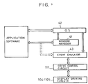
- a frame display control method illustrated in Fig. 9 receives the external display requests 31 to 38 through communication means including a window manager 41 and an operating system (OS) 42 and then transfers the requests to the ferroelectric liquid crystal display apparatus (FLCD) 101. If at least one request is made to rewrite information currently displayed, the frame display control program, according to the display priority of the request, determines the area to be rewritten and the necessary description of data in the VRAM (an image data memory) and selects image data to send to the FLCD 101 while synchronizing the graphic controller 102 and the display apparatus 101.
- VRAM an image data memory
- the OS 42 of the communication means may be MS-DOS (trademark), OS/2 (trademark) or XENIX (trademark) of Microsoft in the USA, or UNIX (trademark) of AT&T in the USA.
- the window manager 41 may be MS-Windows ver. 1.03 or ver. 2.0 (trademarks) of Microsoft in the USA, OS/2 Presentation Manager (trademark) of Microsoft in the USA, public domain X-Window, or DEC-Window (trademark) of Digital Equipment in the USA.
- An event emulator 43 may be a pair of MS-DOS and MS-Windows or a pair of UNIX and X-Window.
- Partial rewriting is performed by scanning only the scanning lines in a partial rewriting area. Since the FLCD 101 has a memory, partial rewriting can be performed. Also it is supposed that, at any particular moment, there will not be many events in which the computer system has to rewrite display information at high speed. For example, information from the pointing device (a mouse, etc.) can be sufficiently displayed at a speed of 30 Hz or less because display at a greater speed can not be followed by the human eye. Also, the speed of smooth scrolling (scrolling in units of a scanning line), which is required to be greater than that of any other display, must stay in a certain range for the same reason. In practice, scrolling is often performed in units of a character or a block instead of a scanning line.
- Scrolling in a computer system is usually performed in order to edit a program or a document, in which case what counts is not smooth scrolling but rather quick shifting from one document line to another (document-line scrolling in units of a document line).
- a display speed of 10 document lines per second is sufficient for document-line scrolling.
- the document-line scrolling at a speed of 10 document lines per second corresponds to frame renewal at 10 Hz by the non-interlace method. Flickering caused by the frame frequency of 10 Hz does not become a problem because the operator's attention is more strongly drawn to display changes caused by the document-line scrolling.
- the display apparatus employs a data format, i.e. image data including scanning line address information, and communication synchronising means using the SYNC signal, as shown in Figs. 6 and 7, so as to be driven according to a partial rewrite scanning method performed by the graphic controller, as described below.
- a data format i.e. image data including scanning line address information
- communication synchronising means using the SYNC signal as shown in Figs. 6 and 7, so as to be driven according to a partial rewrite scanning method performed by the graphic controller, as described below.
- Image data is generated by the graphic controller 102 and transferred to the display panel 103 by the signal transferring means shown in Figs. 6 and 7.
- the graphic controller 102 has a CPU (a central processing unit, referred to as a "GCPU” hereinafter) 112 and a VRAM (an image data memory) 114, which together control management and communication of image data between a host CPU 113 and the liquid crystal display apparatus 102.
- a CPU central processing unit
- VRAM an image data memory
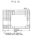
- the scanning line address information is mapped in the VRAM 114 as shown in Fig. 10.
- the VRAM 114 is divided into two areas: one area assigned for scanning line address information and the other area assigned for display information.
- Image data of one scanning line are lined up horizontally and scanning line address information is placed on the leading end (the left end in Fig. 10) of the thus lined-up image data of each scanning line.
- the data mapped in the VRAM 114 correspond, on a one-to-one basis, to the pixels of the display panel 103.
- the GCPU 112 reads out the image data of one line at a time from the left end in the VRAM 114 and sends out the read-out data to the liquid crystal display apparatus 101 so as to achieve the data format, i.e., image data including scanning line address information as well as display information.
- Fig.11 shows a method for partial rewriting.
- the data about the address of the scanning line being currently scanned, the number of scanning lines and the current scanning method (a non-interlace method or a multi-interlace method, and in the case of multi-interlace method, the number of fields composing one frame) is saved (S3) in a register pre-assigned therefor in the GCPU 112 so that processing can return to the normal refresh routine after the partial rewriting routine is completed.
- the image data for the partial rewriting is developed in the VRAM 114 (S4).
- the host CPU 113 is allowed to access to the VRAM 114 solely via the GCPU 112.
- the GCPU 112 manages the area and the starting address in the VRAM 114 to store image data for partial rewriting.
- the GCPU 112 changes scanning methods from multi-interlace scanning to non-interlace scanning according to the image data for partial rewriting (S5, S6). Scanning methods can be changed simply by changing the sequence for reading out image data including scanning line address information from the VRAM 114 shown in Fig. 10. For example, to perform multi-interlace scanning in which eight fields form one frame, lines of image data in the VRAM 114 are read out every eight lines. To perform non-interlace scanning, the lines of image data are read out one after another in their address order. The image data is transferred to the liquid crystal display apparatus (S7), according to the signal transferring method shown in Figs. 6 and 7. The scanning line address information mapped in the VRAM 114 is transferred line by line, always monitored by the GCPU 112. Scanning methods are not changed during transfer of image data for partial rewriting.
- the method checks (S8) whether there is a second request for partial rewriting having a high priority than the partial rewriting being currently processed every time one line of image data has been transferred. If there is a second request for partial rewriting having a higher priority, the transfer of the current (first) partial rewriting image data is stopped, and processing branches to the routine for the second partial rewriting (S9). In the routine for the second partial rewriting, first, the data about the scanning method for the first partial rewriting is stored.
- the scanning method is changed to a scanning method according to the image data for the second partial rewriting, and processing similar to that in the routine for the first partial rewriting is performed (S10-S15).
- the scanning method for the first partial rewriting is restored to return to the routine for the first partial rewriting (S16).
- the remaining image data is transferred (S17) while the method checks for generation of another request for partial rewriting of a higher priority after each process of transferring one line of image data. When all the image data is transferred, processing returns to the normal entire refresh routine based on the pre-saved data about the scanning line address, the number of scanning lines and the scanning method (18).
- Table 2 shows the correspondence between the scanning electrode numbers. (the scanning electrodes are numbered from the top scanning electrode to the bottom scanning electrode in the display panel as 1°, 2°, 3°, ⁇ N°) and the priorities to select scanning methods and scanning electrodes.
- Fig. 12 shows an example of a multiwindow display frame 110.
- a window 1 displays a circle graph exhibiting the result of a certain survey.
- a window 2 displays a table showing the same result exhibited by the circle graph in the window 1.
- a window 3 displays a bar graph exhibiting the same result as above.
- a window 4 displays a document being written and an icon of the mouse, i.e. the pointing device, 5.
- the mouse 5 is moved. Both scrolling and mouse movement requires partial rewriting in the ferroelectric liquid crystal display apparatus 101. If 1120 scanning lines of the entire frame are scanned, the frame frequency will be about 10 Hz since one horizontal scanning period is 80 ⁇ sec according to this embodiment. This frame frequency is not fast enough to follow the normal movement of the mouse 5 ( ⁇ 30 Hz).
- the scrolling in the window 4 and the movement of the mouse 5 correspond to the first and second partial rewriting routines, respectively.
- the first partial rewriting routine scanning methods are changed from multi-interlace scanning for the entire frame refresh routine to non-interlace scanning in order to perform partial rewriting in the window 4.
- Non-interlace scanning is required because the display operation for scrolling in a window requires the ferroelectric liquid crystal display apparatus 101 to quickly change its display and because what is displayed (e.g., characters) must be recognizable during scrolling. If, like page turning, the process of rewriting in the window 4 does not need to be recognizable, a change of scanning methods is not required.
- multi-interlace scanning provides a more stable picture quality than non-interlace scanning.
- Branching to the second partial rewriting routine occurs when the mouse 5 is moved.
- the time required for the branching is one horizontal scanning period at most. Since the moving process of the mouse 5 must be traced as in the scrolling in the window 4, the scanning method for this partial rewriting must be the non-interlace scanning.
- the font size of the mouse 5 is 32 x 32 dots and one horizontal scanning period is 80 ⁇ sec
- the scrolling operation in the window 4 performed by the first partial rewriting routine is stopped, the duration is very short and, therefore, does not significantly affect the scrolling speed.
- processing returns to the first partial rewriting routine in the window 4.
- another mouse movement causes immediate branching to the partial rewriting for the mouse 5, in which the mouse 5 is rewritten by the non-interlace scanning.
- processing returns to the entire refresh routine.
- the window and the mouse are displayed by multi-interlace refresh scanning. If partial rewriting is so performed for predetermined display operations by selecting the appropriate scanning method, the sufficiently fast movement of the mouse and the sufficient display quality of the moving mouse can be achieved even in the low frame-frequency driving unique to ferroelectric liquid crystal display apparatuses.
- the preferred embodiment of the present invention includes means for changing scanning methods according to image data for which partial rewriting is performed. If such image data causes slow display change, multi-interlace scanning is performed in order to maintain picture quality. If such image data causes fast change and requires display of the moving process, such as movement of a mouse or scrolling in a window, non-interlace scanning is performed.
- the embodiment achieves a method suitable for a variety of applications which require the ferroelectric liquid crystal display apparatus to perform partial rewriting and, thereby, smoothly displays sophisticated display application software, such as multiwindow and multitask applications, without causing any problems.
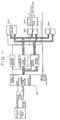
- Fig. 13 is a block diagram of the graphic controller 102.
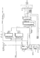
- Fig. 14 is a block diagram of a digital interface.
- Figs. 15 and 16 are timing charts of data transfer.
- the graphic controller 102 is substantially different from conventional graphic controllers in the following features.
- a graphic processor 501 has its own system memory 502.
- the graphic processor 501 not only manages a RAM 503 and a ROM 504 but also executes and manages description commands to the RAM 503. Further, information transfer from a digital interface 505 to the FLCD controller, management of methods of driving the FLCD, etc., can be programmed independently.
- Fig. 14 while the digital interface 505 is performing synchronization with the driving circuits 104 and 105 of the display panel 103 using external synchronizing signals HSYNC ⁇ and VSYNC ⁇ from the FLCD controller 111, the data from the VRAM becomes 4 bits/clock (data transfer clock) at the final stage of the processing by the digital interface 505 and is sent to the FLCD controller 111.
- Fig. 15 shows the timing for the FLCD to perform entire frame rewriting. Parameters used in Fig. 15 are the same as those in Fig. 16. Transfer of one line of image data starts when the HSYNC ⁇ signal becomes active (low level).
- the HSYNC ⁇ signal is made low by the FLCD controller 111 to indicate an information request made by the display panel 103.
- the information request made by the display panel 103 is received by the graphic processor 501 show in Fig. 13and processed therein at the timing shown in Fig. 16.
- the HSYNC ⁇ signal of the information request made by the display panel 103 for one cycle of an external video clock from the outside (CLKOUT) (in other words, for a period of low level of VCLK) is sampled (actually, the VCLK is inputted to the graphic processor 501, which performs such sampling for the period of low level of the VCLK).
- a DATEN becomes active (high) half a clock of the VCLK after the HBLNK ⁇ signal becomes disabled, as shown in Fig. 16.
- Half a clock later, i.e., 4.5 clocks after the sampling of the HSYNC ⁇ signal the image data of the next line is transferred, four bits at a time, from the VRAM to FLCD controller 111.
- the scanning line address information of the next line (corresponding to the scanning line numbers) is sent out four bits at a time, and then, the display information of this line is sent out.
- the FLCD controller 111 discriminates the scanning line address information and the display information by using the AH/DL signal.
- the high level of the AH/DL signal indicates scanning line address information, and the low level of the AH/DL signal indicates display information.
- a scanning line of the FLCD 101 is selected according to scanning line address information, and display information is written into the selected scanning line. Therefore, if the scanning line address information continuously transferred from the graphic controller 102 indicates scanning line numbers which serially increase one by one, the FLCD 101 is driven by non-interlace scanning.
- the FLCD 101 is driven by the interlace scanning. If such scanning line address information indicates scanning line numbers which increase by m, the FLCD is driven by m-multi-interlace scanning.
- the graphic controller 102 thus controls driving methods in the FLCD.
- the time required to drive one scanning line of the FLCD is about 100 ⁇ sec. If the driving time for one scanning line is 100 ⁇ sec, and the lowest possible frequency which causes no flickering is 30 Hz, the following number of scanning lines of the FLCD can be driven without causing flickering in a static image:
- 74AS161A, 74AS74, 74ALS257, 74ALS878 and 74AS257 are IC Nos., and the other numerals are pin Nos.
Abstract
Description
- The present invention relates to a display apparatus for driving a liquid crystal display device operable in both an entire frame scan mode and a partial rewrite scan mode. In particular, but not exclusively, it concerns a display apparatus for driving a ferroelectric liquid crystal display device (FLCD). It relates also to a liquid crystal display device including display apparatus.
- A liquid crystal display device for displaying image information is known which comprises many pixels formed by placing a liquid crystal material between an array of scanning electrodes and an array of information electrodes to constitute a matrix of electrodes. An example of this type of display device is illustrated in Figs. 1 and 2. A scanning method used in such a display device is disclosed, for example, in U.S. Patent No. 4,655,561 (Kanbe et al) and in EP-A-0256879. The method utilises a memory to scan for partial rewriting so as to maintain a smooth display of movements even during low field frequency scanning.
- Another driving waveform is disclosed by Taniguchi et al in European Laid-Open No. 394,903, which helps to speed up the frame frequency and provide a sufficient driving margin, i.e. the range of the driving voltage or the writing pulse width within which images of favourable quality can be displayed.
- A display apparatus for driving a liquid crystal display device operable in both an entire frame scan mode and a partial rewrite scan mode is described in EP-A-0361471. This, in common with the display apparatus of the present invention, comprises drive means, to apply respective driving signals to selected respective scanning electrodes of the device, and to apply data signals to information electrodes of the device, in synchronism with said drive signals; and
- control means, co-operable with said drive means, to cause said drive means to perform either an entire frame scan in which the picture elements of the device are fully rewritten, or a partial rewrite scan in which the picture elements of only a part of the device are rewritten; wherein
- said drive means is operable to apply, during said entire frame scan, driving signals each having a waveform that includes an erase pulse, and following said erase pulse, a write pulse, the effect of which is to produce a resultant voltage across respective picture elements of the device having a time average voltage DC component.
- As described in EP-A-0361471, graphic events are displayed in a predetermined order of priority. Multi-interlaced scanning is used for entire frame scan and non-interlaced scanning is used for partial rewrite scan. The driving signal waveform is the same in both scan modes.
- However, since the scanning waveform according to the above conventional art produces an erasing waveform including a time average voltage DC component, frequent repetition of partial-rewrite scanning on a single scanning electrode causes the following problems in the pixels on that scanning electrode;
- (1) decrease of the driving margin
- (2) deterioration of liquid crystal alignment
- (3) decrease in sharpness of contrast
- The present invention is intended to solve the above problems.
- To substantially avoid a decrease of the driving margin, deterioration of liquid crystal alignment and decrease in sharpness of contrast which are caused during partial-rewrite scanning, the display apparatus according to the present invention is characterised in that:
said drive means includes means of supplying, selecting, and applying during said partial rewrite scan, driving signals having a waveform that includes, or respective waveforms that include, at least a write pulse, the effect of which is to produce a resultant voltage across respective picture elements of the device having no time average voltage DC component. - It is acknowledged that it is known to use driving signals, during an entire frame scan, the effect of which is to produce a resultant voltage, across respective picture elements of a display device, having no time average voltage DC component. There is described in EP-A-0197742 a display device in which data writing is preceded with erasing pulses. The polarity of the erasing and writing driving pulses is periodically reversed to maintain charge balance in the long term.
- Further objects, features and advantages of the present invention will become apparent from the following description of the preferred embodiments with reference to the attached drawings.
- In the accompanying drawings:
- Fig. 1 is a plan view of a display panel;
- Fig. 2 is a sectional view of the display panel shown in Fig. 1;
- Fig. 3 illustrates driving waveforms used in the present invention;
- Fig. 4 illustrates other driving waveforms used in the present invention;
- Fig. 5 illustrates conventional driving waveforms;
- Fig. 6 is a block diagram of a liquid crystal display apparatus and a graphic controller;
- Fig. 7 is a timing chart of image information communication between the liquid crystal display apparatus and the graphic controller of Fig. 1;
- Fig. 8 illustrates a display frame including a plurality of graphic events;
- Fig. 9 is a block diagram of a display control program;
- Fig. 10 illustrates data mapping of scanning line address information and display information on a VRAM;
- Fig. 11 illustrates a method for partial rewriting;
- Fig. 12 illustrates a display frame of a multiwindow display;
- Fig. 13 is a block diagram of a graphic controller;
- Fig. 14 is a block diagram of a digital interface;
- Fig. 15 is an interface timing chart for a display driving apparatus;
- Fig. 16 is an interface timing chart for an FLCD controller.
- Preferred embodiments of the present invention will be described hereinafter with reference to the figures.
- Fig. 3 shows driving waveforms according to a first embodiment of the present invention. During entire frame scanning, waveforms which include black erasing pulses and DC components and which drive two neighbouring scanning lines at a time (double driving) are used. During partial rewriting scanning, waveforms which include no erasing pulses and no DC components and which drive one scanning line at a time (single driving) are used.
- Fig. 4 shows driving waveforms according to a second embodiment of the present invention. During entire frame scanning, waveforms including black erasing pulses and DC components are used. During partial rewriting scanning, waveforms including black erasing pulses and waveforms including white erasing pulses are alternately used. Neither of the waveforms includes a DC component.
- Fig. 5 shows conventional driving waveforms. The same waveforms are used both during entire frame scanning and during partial rewriting scanning.
- Table 3 below shows a comparison between the driving waveforms for the partial rewriting scannings according to the embodiments, shown in Figs. 3 and 4, and the partial rewriting scanning of the conventional art, shown in Fig. 5. Because the driving waveforms according to the embodiments include no DC components, they cause less deterioration in the liquid crystal alignment than the conventional driving waveform and fairly expand driving margins. Because the driving waveforms according to the embodiments do not include erasing pulses or include both black and white erasing pulses to offset each other, they cause less decrease in contrast.
- Frequent repetition of the driving of a scanning electrode, which may well happen in partial rewriting, lowers the threshold of the pixels on the scanning electrode. However, according to the present invention, the amplitude or the writing pulse width during partial rewriting scanning is reduced by a predetermined percentage from the value thereof during entire frame scanning. Therefore, driving substantially at the center of the driving margin can be achieved in any of the scanning methods.
Table 3 Conventional Embodiment 1 Embodiment 2Driving Margin Δ Δ ○ Alignment X ○ ○ Contrast Δ ○ ○ - Fig. 1 is an enlarged view of the
display panel 103. Scanning electrodes C1 to C6 and information electrodes S1 to S6 are arranged in a matrix and form pixels P22 which are the units of display. - Fig. 2 is a sectional view of the
display panel 103 including the scanning line C2 shown in Fig. 1. The figure shows an analyser 161, a polariser 165,glass substrates ferroelectric liquid crystal 163 and aspacer 166. The analyser 161 and the polariser 165 are arranged in crossed nicol. - A liquid crystal display device, operable in both an entire frame scan mode and a partial rewrite mode, in which the aforesaid embodiments can be applied, will now be described.
- Referring to Figs. 6 and 7, a
graphic controller 102 transfers scanning line address information for designating scanning electrodes and image data (PD0 to PD3) for the scanning lines designated by the scanning line address information to adisplay driving circuit 104/105 (composed of a scanningline driving circuit 104 and a data line driving circuit 105) of a liquidcrystal display apparatus 101, which advantageously includes a ferroelectric liquid crystal. In this embodiment, because image data including both scanning line address information and display information are transferred through one communication line, the two kinds of information must be discriminated. Signal AH/DL is used to perform this discrimination, so that a high level of the AH/DL signal indicates scanning line address information, and a low level of the AH/DL signal indicates display information. - Scanning line address information is extracted from the image data PD0 to PD3 by a
drive control circuit 111 of the liquidcrystal display apparatus 101 and then outputted to the scanningline driving circuit 104 at a timing for driving the designated scanning lines. The scanning line address information is inputted into adecoder 106 in the scanningline driving circuit 104. In response to signals from thedecoder 106, a scanningsignal generating circuit 107 drives the designated scanning electrodes of thedisplay panel 103. - On the other hand, display information is fed to a
shift register 108 of the data line drivingcircuit 105. Theshift register 108 shifts the display information in units of four bits using a transfer clock. When theshift register 108 has shifted the display information of one horizontal scanning line, the display information of 1280 pixels is transferred to aline memory 109 connected to theshift register 108. The display information is stored in theline memory 109 for a period equal to one horizontal line scanning period and then outputted as display information signals from the informationsignal generating circuit 110 to the associated information electrodes. - Because the driving of the
display panel 103 in the liquidcrystal display apparatus 101 is not synchronous with generation of scanning line address information and display information in thegraphic controller 102 according to this embodiment, the liquidcrystal display apparatus 101 and thegraphic controller 102 must be synchronized with each other when image data is transferred, by using a SYNC signal. The SYNC signal is generated by thedrive control circuit 111 of the liquidcrystal display apparatus 101 for each horizontal scanning period. Thegraphic controller 102 always monitors SYNC signals. When a SYNC signal is at low level, thegraphic controller 102 transfers image data. When a SYNC signal is at high level, thegraphic controller 102 does not continue to transfer image data after transferring image data of one horizontal scanning line. Referring to Fig. 7, as soon as thegraphic controller 102 detects the low level of the SYNC signal, thegraphic controller 102 changes the AH/DL signal to high level in order to start transferring image data of one horizontal scanning line. Thedrive control circuit 111 of the liquidcrystal display apparatus 101 changes the SYNC signal to high level while image data is being transferred. After one horizontal scanning period, i.e., after data-writing into one horizontal scanning line of thedisplay panel 103 is completed, the drive controller circuit (FLCD controller) 111 changes the SYNC signal back to low level to enable the reception of image data for the next scanning line. - Fig. 8 illustrates a
display frame 3 when the following display requests for display information are made in multiwindow and multitask format: -
display request 31 to smoothly move a mouse diagonally; -
display request 32 to display a portion of a window selected as the active frame, which portion is overlapped by a previously selected window; -
display request 33 to insert characters by key-board input; - display request 34 to move characters already displayed (in a direction indicated by arrow keys);
-
display request 35 for display change in an overlap area; -
display request 36 to display a non-active window; -
display request 37 to perform scrolling in a non-active window; and -
display request 38 for scanning the entire display. - The following Table 1 shows the respective priorities of graphic events corresponding to the above display requests 31 to 38.
-
Table 1 Graphic Event Drive Mode Display Priority Description 31 Mouse Movement Partial Highest Display Rewrite 32 Active Window Area On Logical Access Area 33 Character Partial 2nd Level Insertion Display Rewrite 34 Character Partial 3rd Level Movement Display Rewrite 35 Overlap area Logical VRAM Display change Operation 36 Non-active Logical Access Window Area On Area 37 Non-active Partial 4th Level Window Area Rewrite Scroll Display 38 Entire Multi-field Lowest Scanning Display Refresh - In the above table: "Partial Rewrite" means a driving method which scans only the scanning lines in a partial rewriting area; "Multi-field Refresh" means an entire-frame scanning mode using multi-interlace scanning of N-fields (N = 2, 4, 8, ··· 2n) (a driving method described in Japanese patent application No. 62-287172); "Display Priority" means the priorities assigned to the events beforehand; and "Description" means an internal description operation performed in a graphic processor. In this device the priorities of the events are determined according to operability in a man/machine interface. The top priority is given to the graphic event 31 (mouse movement display), and is followed in descending order by the
graphic events - The mouse movement display is given the top priority because operator's intention expressed by moving the pointing device, i.e., the mouse, should be reflected in the computer as quickly as possible, i.e., in real time. Character input through the key board comes next. Although such key input requires a quite high real-time characteristic, the key input is usually buffered and, therefore, does not require as high a real-time characteristic as the mouse movement display. Frame renewal (scrolling) in the window does not need to be performed simultaneously with the key input, and the document line to which characters are inputted has a higher priority than frame renewal. The display manner of an overlap area in a case where scrolling is performed in an overlapped window varies according to system setting. Document-line scrolling in the overlapped window goes beneath the active window.
- A frame display control method illustrated in Fig. 9 receives the external display requests 31 to 38 through communication means including a
window manager 41 and an operating system (OS) 42 and then transfers the requests to the ferroelectric liquid crystal display apparatus (FLCD) 101. If at least one request is made to rewrite information currently displayed, the frame display control program, according to the display priority of the request, determines the area to be rewritten and the necessary description of data in the VRAM (an image data memory) and selects image data to send to theFLCD 101 while synchronizing thegraphic controller 102 and thedisplay apparatus 101. - The
OS 42 of the communication means may be MS-DOS (trademark), OS/2 (trademark) or XENIX (trademark) of Microsoft in the USA, or UNIX (trademark) of AT&T in the USA. Thewindow manager 41 may be MS-Windows ver. 1.03 or ver. 2.0 (trademarks) of Microsoft in the USA, OS/2 Presentation Manager (trademark) of Microsoft in the USA, public domain X-Window, or DEC-Window (trademark) of Digital Equipment in the USA. Anevent emulator 43 may be a pair of MS-DOS and MS-Windows or a pair of UNIX and X-Window. - Partial rewriting is performed by scanning only the scanning lines in a partial rewriting area. Since the
FLCD 101 has a memory, partial rewriting can be performed. Also it is supposed that, at any particular moment, there will not be many events in which the computer system has to rewrite display information at high speed. For example, information from the pointing device (a mouse, etc.) can be sufficiently displayed at a speed of 30 Hz or less because display at a greater speed can not be followed by the human eye. Also, the speed of smooth scrolling (scrolling in units of a scanning line), which is required to be greater than that of any other display, must stay in a certain range for the same reason. In practice, scrolling is often performed in units of a character or a block instead of a scanning line. Scrolling in a computer system is usually performed in order to edit a program or a document, in which case what counts is not smooth scrolling but rather quick shifting from one document line to another (document-line scrolling in units of a document line). A display speed of 10 document lines per second is sufficient for document-line scrolling. - If partial rewrite scanning in the
FLCD 101 is performed by a non-interlace method in order to display movement of a mouse formed in 32 x 32 dots, the following response speed is possible
- The document-line scrolling at a speed of 10 document lines per second corresponds to frame renewal at 10 Hz by the non-interlace method. Flickering caused by the frame frequency of 10 Hz does not become a problem because the operator's attention is more strongly drawn to display changes caused by the document-line scrolling. The number of scanning lines driven by the non-interlace method during document-line scrolling is

- The display apparatus employs a data format, i.e. image data including scanning line address information, and communication synchronising means using the SYNC signal, as shown in Figs. 6 and 7, so as to be driven according to a partial rewrite scanning method performed by the graphic controller, as described below.
- Image data is generated by the
graphic controller 102 and transferred to thedisplay panel 103 by the signal transferring means shown in Figs. 6 and 7. Thegraphic controller 102 has a CPU (a central processing unit, referred to as a "GCPU" hereinafter) 112 and a VRAM (an image data memory) 114, which together control management and communication of image data between ahost CPU 113 and the liquidcrystal display apparatus 102. - To obtain this data format, i.e. image data including scanning line address information, the scanning line address information is mapped in the
VRAM 114 as shown in Fig. 10. TheVRAM 114 is divided into two areas: one area assigned for scanning line address information and the other area assigned for display information. Image data of one scanning line are lined up horizontally and scanning line address information is placed on the leading end (the left end in Fig. 10) of the thus lined-up image data of each scanning line. As a result, the data mapped in theVRAM 114 correspond, on a one-to-one basis, to the pixels of thedisplay panel 103. TheGCPU 112 reads out the image data of one line at a time from the left end in theVRAM 114 and sends out the read-out data to the liquidcrystal display apparatus 101 so as to achieve the data format, i.e., image data including scanning line address information as well as display information. - Fig.11 shows a method for partial rewriting.
- If there is no request for partial rewriting (S1), an entire frame is scanned by the multi-interlace method (entire frame refresh driving) (S2). The image data (data about the pointing device, the pop-up menu, etc.) necessary for the ferroelectric liquid
crystal display apparatus 101 to perform partial rewriting is registered beforehand in theGCPU 112 and the method branches to partial rewriting according to information from thehost CPU 113. Immediately before branching to partial rewriting, the data about the address of the scanning line being currently scanned, the number of scanning lines and the current scanning method (a non-interlace method or a multi-interlace method, and in the case of multi-interlace method, the number of fields composing one frame) is saved (S3) in a register pre-assigned therefor in theGCPU 112 so that processing can return to the normal refresh routine after the partial rewriting routine is completed. Then, the image data for the partial rewriting is developed in the VRAM 114 (S4). Thehost CPU 113 is allowed to access to theVRAM 114 solely via theGCPU 112. TheGCPU 112 manages the area and the starting address in theVRAM 114 to store image data for partial rewriting. - After the image data is stored in the
VRAM 114, transfer of the image data to the liquidcrystal display apparatus 101 is started. For this transfer, theGCPU 112 changes scanning methods from multi-interlace scanning to non-interlace scanning according to the image data for partial rewriting (S5, S6). Scanning methods can be changed simply by changing the sequence for reading out image data including scanning line address information from theVRAM 114 shown in Fig. 10. For example, to perform multi-interlace scanning in which eight fields form one frame, lines of image data in theVRAM 114 are read out every eight lines. To perform non-interlace scanning, the lines of image data are read out one after another in their address order. The image data is transferred to the liquid crystal display apparatus (S7), according to the signal transferring method shown in Figs. 6 and 7. The scanning line address information mapped in theVRAM 114 is transferred line by line, always monitored by theGCPU 112. Scanning methods are not changed during transfer of image data for partial rewriting. - To handle a second request for partial rewriting generated during processing of partial rewriting, the method checks (S8) whether there is a second request for partial rewriting having a high priority than the partial rewriting being currently processed every time one line of image data has been transferred. If there is a second request for partial rewriting having a higher priority, the transfer of the current (first) partial rewriting image data is stopped, and processing branches to the routine for the second partial rewriting (S9). In the routine for the second partial rewriting, first, the data about the scanning method for the first partial rewriting is stored. Then, the scanning method is changed to a scanning method according to the image data for the second partial rewriting, and processing similar to that in the routine for the first partial rewriting is performed (S10-S15). Finally, the scanning method for the first partial rewriting is restored to return to the routine for the first partial rewriting (S16). Back in the routine for the first partial rewriting, the remaining image data is transferred (S17) while the method checks for generation of another request for partial rewriting of a higher priority after each process of transferring one line of image data. When all the image data is transferred, processing returns to the normal entire refresh routine based on the pre-saved data about the scanning line address, the number of scanning lines and the scanning method (18).
- Table 2 below shows the correspondence between the scanning electrode numbers. (the scanning electrodes are numbered from the top scanning electrode to the bottom scanning electrode in the display panel as 1°, 2°, 3°, ··· N°) and the priorities to select scanning methods and scanning electrodes.


- Fig. 12 shows an example of a
multiwindow display frame 110. Awindow 1 displays a circle graph exhibiting the result of a certain survey. Awindow 2 displays a table showing the same result exhibited by the circle graph in thewindow 1. Awindow 3 displays a bar graph exhibiting the same result as above. Awindow 4 displays a document being written and an icon of the mouse, i.e. the pointing device, 5. - In the figure, let it be supposed that the
windows 1 to 3 are non-active and that while scrolling is being performed in thewindow 4 to edit the document, themouse 5 is moved. Both scrolling and mouse movement requires partial rewriting in the ferroelectric liquidcrystal display apparatus 101. If 1120 scanning lines of the entire frame are scanned, the frame frequency will be about 10 Hz since one horizontal scanning period is 80 µsec according to this embodiment. This frame frequency is not fast enough to follow the normal movement of the mouse 5 (≥ 30 Hz). - If the partial rewriting method shown in Fig. 11 is used in this case, the scrolling in the
window 4 and the movement of themouse 5 correspond to the first and second partial rewriting routines, respectively. In the first partial rewriting routine, scanning methods are changed from multi-interlace scanning for the entire frame refresh routine to non-interlace scanning in order to perform partial rewriting in thewindow 4. Non-interlace scanning is required because the display operation for scrolling in a window requires the ferroelectric liquidcrystal display apparatus 101 to quickly change its display and because what is displayed (e.g., characters) must be recognizable during scrolling. If, like page turning, the process of rewriting in thewindow 4 does not need to be recognizable, a change of scanning methods is not required. In such a case, multi-interlace scanning provides a more stable picture quality than non-interlace scanning. Branching to the second partial rewriting routine occurs when themouse 5 is moved. The time required for the branching is one horizontal scanning period at most. Since the moving process of themouse 5 must be traced as in the scrolling in thewindow 4, the scanning method for this partial rewriting must be the non-interlace scanning. If the font size of themouse 5 is 32 x 32 dots and one horizontal scanning period is 80 µsec, the time required to write themouse 5 in the display panel is
window 4 performed by the first partial rewriting routine is stopped, the duration is very short and, therefore, does not significantly affect the scrolling speed. After themouse 5 is rewritten in, processing returns to the first partial rewriting routine in thewindow 4. However, another mouse movement causes immediate branching to the partial rewriting for themouse 5, in which themouse 5 is rewritten by the non-interlace scanning. When the first and second partial rewriting routines are completed, processing returns to the entire refresh routine. - When there is no display change in a window or no movement of the mouse, the window and the mouse are displayed by multi-interlace refresh scanning. If partial rewriting is so performed for predetermined display operations by selecting the appropriate scanning method, the sufficiently fast movement of the mouse and the sufficient display quality of the moving mouse can be achieved even in the low frame-frequency driving unique to ferroelectric liquid crystal display apparatuses.
- The preferred embodiment of the present invention includes means for changing scanning methods according to image data for which partial rewriting is performed. If such image data causes slow display change, multi-interlace scanning is performed in order to maintain picture quality. If such image data causes fast change and requires display of the moving process, such as movement of a mouse or scrolling in a window, non-interlace scanning is performed. Thus, the embodiment achieves a method suitable for a variety of applications which require the ferroelectric liquid crystal display apparatus to perform partial rewriting and, thereby, smoothly displays sophisticated display application software, such as multiwindow and multitask applications, without causing any problems.
- Fig. 13 is a block diagram of the
graphic controller 102. Fig. 14 is a block diagram of a digital interface. Figs. 15 and 16 are timing charts of data transfer. - The
graphic controller 102 is substantially different from conventional graphic controllers in the following features. As shown in Fig.13 agraphic processor 501 has itsown system memory 502. Thegraphic processor 501 not only manages aRAM 503 and aROM 504 but also executes and manages description commands to theRAM 503. Further, information transfer from adigital interface 505 to the FLCD controller, management of methods of driving the FLCD, etc., can be programmed independently. - Referring to Fig. 14, while the
digital interface 505 is performing synchronization with the drivingcircuits display panel 103 using external synchronizing signals

FLCD controller 111, the data from the VRAM becomes 4 bits/clock (data transfer clock) at the final stage of the processing by thedigital interface 505 and is sent to theFLCD controller 111. Fig. 15 shows the timing for the FLCD to perform entire frame rewriting. Parameters used in Fig. 15 are the same as those in Fig. 16. Transfer of one line of image data starts when the

FLCD controller 111 to indicate an information request made by thedisplay panel 103. The information request made by thedisplay panel 103 is received by thegraphic processor 501 show in Fig. 13and processed therein at the timing shown in Fig. 16. According to the timing chart shown in Fig. 16,the
display panel 103 for one cycle of an external video clock from the outside (CLKOUT) (in other words, for a period of low level of VCLK) is sampled (actually, the VCLK is inputted to thegraphic processor 501, which performs such sampling for the period of low level of the VCLK). Two and half clocks of the VCLK after such sampling, a horizontal counter HCOUNT in thegraphic processor 501 is cleared. Then,


FLCD controller 111. - AS shown in the bottom-right portion of Fig. 16, first, the scanning line address information of the next line (corresponding to the scanning line numbers) is sent out four bits at a time, and then, the display information of this line is sent out. The
FLCD controller 111 discriminates the scanning line address information and the display information by using the AH/DL signal. The high level of the AH/DL signal indicates scanning line address information, and the low level of the AH/DL signal indicates display information. A scanning line of theFLCD 101 is selected according to scanning line address information, and display information is written into the selected scanning line. Therefore, if the scanning line address information continuously transferred from thegraphic controller 102 indicates scanning line numbers which serially increase one by one, theFLCD 101 is driven by non-interlace scanning. If such scanning line address information indicates scanning line numbers which increase by two, theFLCD 101 is driven by the interlace scanning. If such scanning line address information indicates scanning line numbers which increase by m, the FLCD is driven by m-multi-interlace scanning. Thegraphic controller 102 thus controls driving methods in the FLCD. - The time required to drive one scanning line of the FLCD is about 100 µsec. If the driving time for one scanning line is 100 µsec, and the lowest possible frequency which causes no flickering is 30 Hz, the following number of scanning lines of the FLCD can be driven without causing flickering in a static image:
- by non-interlace driving
[Calculation 3] (1/30Hz)/100µsec ≈ 333 (lines) - by interlace driving
[Calculation 4] (1/30Hz) x 2/100µsec ≈ 666 (lines) - by m-multi-interlace driving
[Calculation 5] (1/30Hz) x m/100µsec ≈ 333 x m (lines) - In Fig. 14, 74AS161A, 74AS74, 74ALS257, 74ALS878 and 74AS257 are IC Nos., and the other numerals are pin Nos.
- While the present invention has been described with respect to what is presently considered to be the preferred embodiments, it is to be understood that the invention is not limited to the disclosed embodiments. To the contrary, the invention is intended to cover various modifications and equivalent arrangements included within the scope of the appended claims.
Claims (7)
- A display apparatus for driving a liquid crystal display device (101) operable in both an entire frame scan mode and a partial rewrite scan mode, said apparatus comprising:drive means (107,110), to apply respective driving signals to selected respective scanning electrodes (21: C1-C6) of the device, and to apply data signals to information electrodes (22: S1-S6) of the device, in synchronism with said drive signals; andcontrol means (111), co-operable with said drive means (107,110), to cause said drive means (107,110) to perform either an entire frame scan in which the picture elements (P22, ...) of the device are fully rewritten, or a partial rewrite scan in which the picture elements (P22, ...) of only a part of the device are rewritten; whereinsaid drive means (107,110) is operable to apply, during said entire frame scan, driving signals each having a waveform that includes an erase pulse, and following said erase pulse, a write pulse, the effect of which is to produce a resultant voltage across respective picture elements (P22, ...) of the device having a time average voltage DC component; which display apparatus is characterised in that:said drive means (107,110) includes means (107) of supplying, selecting, and applying during said partial rewrite scan, driving signals having a waveform that includes, or respective waveforms that include, at least a write pulse, the effect of which is to produce a resultant voltage across respective picture elements (P22, ...) of the device having no time average voltage DC component.
- A display apparatus according to claim 1 wherein said drive means (107,110) is operable to apply in successive partial rewrite scan cycles alternately a driving signal the waveform of which includes a black erasing pulse and a writing pulse and a driving signal the waveform of which includes a white erasing pulse and a writing pulse.
- A display apparatus according to claim 1 wherein said drive means (107,110) is operable to apply during partial rewrite scan a driving signal the waveform of which includes no erasing pulse.
- A display apparatus according to claim 1 wherein said drive means (107,110) is operable to apply, during entire frame scan, driving signals to two scanning electrodes (C1 and C2, C2 and C3, ...) at a time, the waveforms thereof overlapping such that an erasing pulse is applied to one of the two electrodes (C2,C3,...) while a writing pulse is applied to the other scanning electrode (C1, C2, ...) and during partial rewrite scan, a driving signal is applied to one scanning electrode (C1,C2,C3,...) at a time.
- A display apparatus according to any preceding claim wherein said drive means (107,110) is operable to apply during partial rewrite scan a driving signal the amplitude or the writing pulse width of which is reduced compared to that of the driving signal applied during entire frame scan, to perform driving at the centre of the driving margin.
- A liquid crystal display device comprising a liquid crystal material (163) between an array of scanning electrodes (21: C1-C6) and an array of information electrodes (22: S1-S6) constituting a matrix of electrodes (101), which display device is operable in both an entire frame scan mode and a partial rewrite scan mode and includes a display apparatus as claimed in any preceding claim.
- A liquid crystal display device according to claim 6 wherein said liquid crystal material (163) is a ferroelectric liquid crystal material.
Applications Claiming Priority (4)
| Application Number | Priority Date | Filing Date | Title |
|---|---|---|---|
| JP145996/91 | 1991-06-18 | ||
| JP14599691 | 1991-06-18 | ||
| JP11760792A JP3227197B2 (en) | 1991-06-18 | 1992-05-11 | Display device |
| JP117607/92 | 1992-05-11 |
Publications (3)
| Publication Number | Publication Date |
|---|---|
| EP0519717A2 EP0519717A2 (en) | 1992-12-23 |
| EP0519717A3 EP0519717A3 (en) | 1993-08-25 |
| EP0519717B1 true EP0519717B1 (en) | 1997-01-08 |
Family
ID=26455704
Family Applications (1)
| Application Number | Title | Priority Date | Filing Date |
|---|---|---|---|
| EP92305574A Expired - Lifetime EP0519717B1 (en) | 1991-06-18 | 1992-06-17 | Display apparatus |
Country Status (5)
| Country | Link |
|---|---|
| US (1) | US5321419A (en) |
| EP (1) | EP0519717B1 (en) |
| JP (1) | JP3227197B2 (en) |
| AT (1) | ATE147531T1 (en) |
| DE (1) | DE69216482T2 (en) |
Families Citing this family (39)
| Publication number | Priority date | Publication date | Assignee | Title |
|---|---|---|---|---|
| US5815130A (en) * | 1989-04-24 | 1998-09-29 | Canon Kabushiki Kaisha | Chiral smectic liquid crystal display and method of selectively driving the scanning and data electrodes |
| US6124842A (en) * | 1989-10-06 | 2000-09-26 | Canon Kabushiki Kaisha | Display apparatus |
| JP2802685B2 (en) * | 1991-01-08 | 1998-09-24 | キヤノン株式会社 | Ferroelectric liquid crystal device |
| JP3156977B2 (en) * | 1992-05-19 | 2001-04-16 | キヤノン株式会社 | Display control device and method |
| DE69314921T2 (en) * | 1992-12-25 | 1998-03-19 | Canon Kk | Liquid crystal display device |
| US5592190A (en) * | 1993-04-28 | 1997-01-07 | Canon Kabushiki Kaisha | Liquid crystal display apparatus and drive method |
| JP3524122B2 (en) * | 1993-05-25 | 2004-05-10 | キヤノン株式会社 | Display control device |
| JP2942161B2 (en) * | 1993-12-28 | 1999-08-30 | キヤノン株式会社 | Liquid crystal alignment treatment method, liquid crystal element manufacturing method using the method, and liquid crystal element |
| US5943035A (en) * | 1994-04-20 | 1999-08-24 | Canon Kabushiki Kaisha | Driving method and apparatus for liquid crystal device |
| DE69524013T2 (en) * | 1994-09-12 | 2002-06-06 | Canon Kk | Control for a ferroelectrical liquid crystal device |
| EP0703561A3 (en) * | 1994-09-26 | 1996-12-18 | Canon Kk | Driving method for display device and display apparatus |
| US5808594A (en) * | 1994-09-26 | 1998-09-15 | Canon Kabushiki Kaisha | Driving method for display device and display apparatus |
| US6075511A (en) * | 1995-02-27 | 2000-06-13 | Canon Kabushiki Kaisha | Drive voltages switched depending upon temperature detection of chiral smectic liquid crystal displays |
| US5986736A (en) * | 1995-04-26 | 1999-11-16 | Canon Kabushiki Kaisha | Liquid crystal device, image display apparatus and image forming apparatus |
| US5933128A (en) * | 1995-05-17 | 1999-08-03 | Canon Kabushiki Kaisha | Chiral smectic liquid crystal apparatus and driving method therefor |
| US6061044A (en) * | 1995-05-30 | 2000-05-09 | Canon Kabushiki Kaisha | Liquid-crystal display apparatus |
| KR100337865B1 (en) * | 1995-09-05 | 2002-12-16 | 삼성에스디아이 주식회사 | Method for driving liquid crystal display device |
| JP3182070B2 (en) * | 1996-01-16 | 2001-07-03 | キヤノン株式会社 | Liquid crystal element and driving method of liquid crystal element |
| US5734365A (en) * | 1996-01-25 | 1998-03-31 | Canon Kabushiki Kaisha | Liquid crystal display apparatus |
| US6028579A (en) * | 1996-06-12 | 2000-02-22 | Canon Kabushiki Kaisha | Driving method for liquid crystal devices |
| US6452581B1 (en) | 1997-04-11 | 2002-09-17 | Canon Kabushiki Kaisha | Driving method for liquid crystal device and liquid crystal apparatus |
| US6222517B1 (en) | 1997-07-23 | 2001-04-24 | Canon Kabushiki Kaisha | Liquid crystal apparatus |
| US6323850B1 (en) | 1998-04-30 | 2001-11-27 | Canon Kabushiki Kaisha | Driving method for liquid crystal device |
| JP3347678B2 (en) | 1998-06-18 | 2002-11-20 | キヤノン株式会社 | Liquid crystal device and driving method thereof |
| US6054980A (en) * | 1999-01-06 | 2000-04-25 | Genesis Microchip, Corp. | Display unit displaying images at a refresh rate less than the rate at which the images are encoded in a received display signal |
| US6670937B1 (en) | 1999-03-01 | 2003-12-30 | Canon Kabushiki Kaisha | Liquid crystal display apparatus |
| JP2001282203A (en) * | 2000-03-31 | 2001-10-12 | Minolta Co Ltd | Display device, method for driving the same, portable information terminal and portable communication terminal |
| EP1130568A3 (en) | 2000-03-01 | 2003-09-10 | Minolta Co., Ltd. | Liquid crystal display device |
| JP2001312260A (en) * | 2000-04-28 | 2001-11-09 | Konami Computer Entertainment Japan Inc | Image display method, game system, and computer- readable recording medium with picture display program recorded thereon |
| US7034791B1 (en) | 2000-12-14 | 2006-04-25 | Gary Odom | Digital video display employing minimal visual conveyance |
| EP1387344A3 (en) * | 2002-08-01 | 2006-07-26 | Lg Electronics Inc. | Method and apparatus for driving plasma display panel |
| JP3928528B2 (en) * | 2002-09-20 | 2007-06-13 | コニカミノルタホールディングス株式会社 | Liquid crystal display |
| US9075559B2 (en) | 2009-02-27 | 2015-07-07 | Nvidia Corporation | Multiple graphics processing unit system and method |
| US9135675B2 (en) | 2009-06-15 | 2015-09-15 | Nvidia Corporation | Multiple graphics processing unit display synchronization system and method |
| US20140184611A1 (en) * | 2012-12-31 | 2014-07-03 | Nvidia Corporation | Method and apparatus for sending partial frame updates rendered in a graphics processor to a display using framelock signals |
| US9818379B2 (en) | 2013-08-08 | 2017-11-14 | Nvidia Corporation | Pixel data transmission over multiple pixel interfaces |
| US9293119B2 (en) | 2014-01-06 | 2016-03-22 | Nvidia Corporation | Method and apparatus for optimizing display updates on an interactive display device |
| US9383851B2 (en) | 2014-01-06 | 2016-07-05 | Nvidia Corporation | Method and apparatus for buffering sensor input in a low power system state |
| JP6900279B2 (en) | 2016-09-13 | 2021-07-07 | キヤノン株式会社 | Toner and toner manufacturing method |
Citations (2)
| Publication number | Priority date | Publication date | Assignee | Title |
|---|---|---|---|---|
| EP0066983A2 (en) * | 1981-05-27 | 1982-12-15 | SORD Computer Systems, Inc. | Method of and apparatus for controlling the display of video signal information |
| EP0416172A2 (en) * | 1989-09-08 | 1991-03-13 | Canon Kabushiki Kaisha | Information processing system with display panel |
Family Cites Families (16)
| Publication number | Priority date | Publication date | Assignee | Title |
|---|---|---|---|---|
| US4655561A (en) * | 1983-04-19 | 1987-04-07 | Canon Kabushiki Kaisha | Method of driving optical modulation device using ferroelectric liquid crystal |
| US4691200A (en) * | 1984-10-01 | 1987-09-01 | Xerox Corporation | Matrix display with a fast cursor |
| GB2173336B (en) * | 1985-04-03 | 1988-04-27 | Stc Plc | Addressing liquid crystal cells |
| US4898456A (en) * | 1985-04-23 | 1990-02-06 | Canon Kabushiki Kaisha | Liquid crystal optical device |
| FR2581209B1 (en) * | 1985-04-26 | 1993-11-05 | Canon Kk | LIQUID CRYSTAL OPTICAL DEVICE |
| JPS62278540A (en) * | 1986-05-27 | 1987-12-03 | Canon Inc | Liquid crystal element and its orientation control method and driving method |
| JPS62287172A (en) * | 1986-06-05 | 1987-12-14 | Nec Corp | Test circuit |
| US4901066A (en) * | 1986-12-16 | 1990-02-13 | Matsushita Electric Industrial Co., Ltd. | Method of driving an optical modulation device |
| EP0606929B1 (en) * | 1987-11-12 | 2001-05-30 | Canon Kabushiki Kaisha | Liquid crystal apparatus |
| CA1319767C (en) * | 1987-11-26 | 1993-06-29 | Canon Kabushiki Kaisha | Display apparatus |
| JPH01288830A (en) * | 1988-05-17 | 1989-11-21 | Citizen Watch Co Ltd | Method of driving matrix type ferroelectric liquid crystal panel |
| JP2651204B2 (en) * | 1988-07-14 | 1997-09-10 | キヤノン株式会社 | Driving method of liquid crystal device |
| JP2614280B2 (en) * | 1988-08-17 | 1997-05-28 | キヤノン株式会社 | Liquid crystal device |
| AU617006B2 (en) * | 1988-09-29 | 1991-11-14 | Canon Kabushiki Kaisha | Data processing system and apparatus |
| JP2660566B2 (en) * | 1988-12-15 | 1997-10-08 | キヤノン株式会社 | Ferroelectric liquid crystal device and driving method thereof |
| JP2652886B2 (en) * | 1989-04-24 | 1997-09-10 | キヤノン株式会社 | Driving method of liquid crystal device |
-
1992
- 1992-05-11 JP JP11760792A patent/JP3227197B2/en not_active Expired - Fee Related
- 1992-06-17 EP EP92305574A patent/EP0519717B1/en not_active Expired - Lifetime
- 1992-06-17 US US07/899,720 patent/US5321419A/en not_active Expired - Fee Related
- 1992-06-17 AT AT92305574T patent/ATE147531T1/en not_active IP Right Cessation
- 1992-06-17 DE DE69216482T patent/DE69216482T2/en not_active Expired - Fee Related
Patent Citations (2)
| Publication number | Priority date | Publication date | Assignee | Title |
|---|---|---|---|---|
| EP0066983A2 (en) * | 1981-05-27 | 1982-12-15 | SORD Computer Systems, Inc. | Method of and apparatus for controlling the display of video signal information |
| EP0416172A2 (en) * | 1989-09-08 | 1991-03-13 | Canon Kabushiki Kaisha | Information processing system with display panel |
Also Published As
| Publication number | Publication date |
|---|---|
| ATE147531T1 (en) | 1997-01-15 |
| EP0519717A3 (en) | 1993-08-25 |
| JPH05127629A (en) | 1993-05-25 |
| EP0519717A2 (en) | 1992-12-23 |
| JP3227197B2 (en) | 2001-11-12 |
| DE69216482D1 (en) | 1997-02-20 |
| DE69216482T2 (en) | 1997-05-15 |
| US5321419A (en) | 1994-06-14 |
Similar Documents
| Publication | Publication Date | Title |
|---|---|---|
| EP0519717B1 (en) | Display apparatus | |
| EP0416172B1 (en) | Information processing system with display panel | |
| EP0690431B1 (en) | Display apparatus | |
| US5543817A (en) | Data processing system and apparatus | |
| US5481274A (en) | Display control device | |
| EP0433540B1 (en) | Information processing apparatus and display system | |
| US5675354A (en) | Liquid crystal apparatus | |
| JP2738846B2 (en) | Information processing device | |
| JP2738845B2 (en) | Display device and drive control device | |
| JP2633032B2 (en) | Information processing system and device | |
| JP2662427B2 (en) | Information processing device | |
| JP2714053B2 (en) | Information processing device | |
| JP2729049B2 (en) | Display device | |
| JP2770961B2 (en) | Information processing device | |
| JP2584872B2 (en) | Information processing device | |
| JP2801218B2 (en) | Display device |
Legal Events
| Date | Code | Title | Description |
|---|---|---|---|
| PUAI | Public reference made under article 153(3) epc to a published international application that has entered the european phase |
Free format text: ORIGINAL CODE: 0009012 |
|
| AK | Designated contracting states |
Kind code of ref document: A2 Designated state(s): AT BE CH DE DK ES FR GB GR IT LI LU NL PT SE |
|
| PUAL | Search report despatched |
Free format text: ORIGINAL CODE: 0009013 |
|
| AK | Designated contracting states |
Kind code of ref document: A3 Designated state(s): AT BE CH DE DK ES FR GB GR IT LI LU NL PT SE |
|
| 17P | Request for examination filed |
Effective date: 19940118 |
|
| 17Q | First examination report despatched |
Effective date: 19950724 |
|
| GRAG | Despatch of communication of intention to grant |
Free format text: ORIGINAL CODE: EPIDOS AGRA |
|
| GRAH | Despatch of communication of intention to grant a patent |
Free format text: ORIGINAL CODE: EPIDOS IGRA |
|
| GRAH | Despatch of communication of intention to grant a patent |
Free format text: ORIGINAL CODE: EPIDOS IGRA |
|
| GRAA | (expected) grant |
Free format text: ORIGINAL CODE: 0009210 |
|
| AK | Designated contracting states |
Kind code of ref document: B1 Designated state(s): AT BE CH DE DK ES FR GB GR IT LI LU NL PT SE |
|
| PG25 | Lapsed in a contracting state [announced via postgrant information from national office to epo] |
Ref country code: NL Free format text: LAPSE BECAUSE OF FAILURE TO SUBMIT A TRANSLATION OF THE DESCRIPTION OR TO PAY THE FEE WITHIN THE PRESCRIBED TIME-LIMIT Effective date: 19970108 Ref country code: LI Effective date: 19970108 Ref country code: GR Free format text: LAPSE BECAUSE OF FAILURE TO SUBMIT A TRANSLATION OF THE DESCRIPTION OR TO PAY THE FEE WITHIN THE PRESCRIBED TIME-LIMIT Effective date: 19970108 Ref country code: ES Free format text: THE PATENT HAS BEEN ANNULLED BY A DECISION OF A NATIONAL AUTHORITY Effective date: 19970108 Ref country code: DK Effective date: 19970108 Ref country code: CH Effective date: 19970108 Ref country code: BE Effective date: 19970108 Ref country code: AT Effective date: 19970108 |
|
| REF | Corresponds to: |
Ref document number: 147531 Country of ref document: AT Date of ref document: 19970115 Kind code of ref document: T |
|
| REG | Reference to a national code |
Ref country code: CH Ref legal event code: EP |
|
| REF | Corresponds to: |
Ref document number: 69216482 Country of ref document: DE Date of ref document: 19970220 |
|
| ET | Fr: translation filed | ||
| ITF | It: translation for a ep patent filed |
Owner name: 0403;03RMFSOCIETA' ITALIANA BREVETTI S.P |
|
| PG25 | Lapsed in a contracting state [announced via postgrant information from national office to epo] |
Ref country code: SE Effective date: 19970408 Ref country code: PT Effective date: 19970408 |
|
| NLV1 | Nl: lapsed or annulled due to failure to fulfill the requirements of art. 29p and 29m of the patents act | ||
| PG25 | Lapsed in a contracting state [announced via postgrant information from national office to epo] |
Ref country code: LU Free format text: LAPSE BECAUSE OF NON-PAYMENT OF DUE FEES Effective date: 19970630 |
|
| REG | Reference to a national code |
Ref country code: CH Ref legal event code: PL |
|
| PLBE | No opposition filed within time limit |
Free format text: ORIGINAL CODE: 0009261 |
|
| STAA | Information on the status of an ep patent application or granted ep patent |
Free format text: STATUS: NO OPPOSITION FILED WITHIN TIME LIMIT |
|
| 26N | No opposition filed | ||
| REG | Reference to a national code |
Ref country code: GB Ref legal event code: IF02 |
|
| PGFP | Annual fee paid to national office [announced via postgrant information from national office to epo] |
Ref country code: GB Payment date: 20030603 Year of fee payment: 12 |
|
| PGFP | Annual fee paid to national office [announced via postgrant information from national office to epo] |
Ref country code: FR Payment date: 20030620 Year of fee payment: 12 |
|
| PGFP | Annual fee paid to national office [announced via postgrant information from national office to epo] |
Ref country code: DE Payment date: 20030626 Year of fee payment: 12 |
|
| PG25 | Lapsed in a contracting state [announced via postgrant information from national office to epo] |
Ref country code: GB Free format text: LAPSE BECAUSE OF NON-PAYMENT OF DUE FEES Effective date: 20040617 |
|
| PG25 | Lapsed in a contracting state [announced via postgrant information from national office to epo] |
Ref country code: DE Free format text: LAPSE BECAUSE OF NON-PAYMENT OF DUE FEES Effective date: 20050101 |
|
| GBPC | Gb: european patent ceased through non-payment of renewal fee |
Effective date: 20040617 |
|
| PG25 | Lapsed in a contracting state [announced via postgrant information from national office to epo] |
Ref country code: FR Free format text: LAPSE BECAUSE OF NON-PAYMENT OF DUE FEES Effective date: 20050228 |
|
| REG | Reference to a national code |
Ref country code: FR Ref legal event code: ST |
|
| PG25 | Lapsed in a contracting state [announced via postgrant information from national office to epo] |
Ref country code: IT Free format text: LAPSE BECAUSE OF NON-PAYMENT OF DUE FEES Effective date: 20050617 |