EP0507499A2 - Orthogonal transform coding apparatus for digital audio signals - Google Patents
Orthogonal transform coding apparatus for digital audio signals Download PDFInfo
- Publication number
- EP0507499A2 EP0507499A2 EP92302617A EP92302617A EP0507499A2 EP 0507499 A2 EP0507499 A2 EP 0507499A2 EP 92302617 A EP92302617 A EP 92302617A EP 92302617 A EP92302617 A EP 92302617A EP 0507499 A2 EP0507499 A2 EP 0507499A2
- Authority
- EP
- European Patent Office
- Prior art keywords
- block
- signal
- spectrum
- floating
- orthogonal transform
- Prior art date
- Legal status (The legal status is an assumption and is not a legal conclusion. Google has not performed a legal analysis and makes no representation as to the accuracy of the status listed.)
- Granted
Links
Images


Classifications
-
- H—ELECTRICITY
- H03—ELECTRONIC CIRCUITRY
- H03M—CODING; DECODING; CODE CONVERSION IN GENERAL
- H03M7/00—Conversion of a code where information is represented by a given sequence or number of digits to a code where the same, similar or subset of information is represented by a different sequence or number of digits
-
- H—ELECTRICITY
- H04—ELECTRIC COMMUNICATION TECHNIQUE
- H04B—TRANSMISSION
- H04B1/00—Details of transmission systems, not covered by a single one of groups H04B3/00 - H04B13/00; Details of transmission systems not characterised by the medium used for transmission
- H04B1/66—Details of transmission systems, not covered by a single one of groups H04B3/00 - H04B13/00; Details of transmission systems not characterised by the medium used for transmission for reducing bandwidth of signals; for improving efficiency of transmission
- H04B1/665—Details of transmission systems, not covered by a single one of groups H04B3/00 - H04B13/00; Details of transmission systems not characterised by the medium used for transmission for reducing bandwidth of signals; for improving efficiency of transmission using psychoacoustic properties of the ear, e.g. masking effect
Landscapes
- Engineering & Computer Science (AREA)
- Computer Networks & Wireless Communication (AREA)
- Signal Processing (AREA)
- Theoretical Computer Science (AREA)
- Compression, Expansion, Code Conversion, And Decoders (AREA)
- Reduction Or Emphasis Of Bandwidth Of Signals (AREA)
- Transmission Systems Not Characterized By The Medium Used For Transmission (AREA)
- Image Processing (AREA)
- Compression Or Coding Systems Of Tv Signals (AREA)
Abstract
Description
- This invention relates to coding apparatus for digital signals.
- One way of achieving bit compression when encoding, for example, an audio signal, uses the so-called block floating method in which input data are divided into data blocks every predetermined number of words, and floating processing is effected on each block. In this method the maximum absolute value of the words in each block is found, and floating processing is effected using this maximum absolute value as a common floating coefficient for all the words in that block.
- Another known method uses so-called orthogonal transform coding to transform a signal on the time base to a signal on the frequency base for encoding. Such orthogonal transform coding may comprise fast fourier transform (FFT) or discrete cosine transform (DCT) processing of audio PCM data every fixed number of words (number of samples) in the time base direction.
- There has also been proposed a coding apparatus for a digital signal, in which the above methods are combined thereby to divide a signal on the frequency base into signal components in blocks of predetermined frequency band, for example, the so-called critical band and carry out floating processing on each block.
- Figure 11 shows the configuration of part of a coding apparatus for a digital signal, in which orthogonal transform and block floating processing are combined.
- In Figure 11, a digital signal, such as an audio PCM signal, supplied to an
input terminal 41 is temporarily stored in abuffer memory 42, and is then orthogonally transformed, for example, by acircuit 43 for orthogonal transform, such as FFT. In Figure 11, there is shown the part of the circuit for the (K-1)-th and K-th critical bands where, for example, the number of spectrum components (FFT coefficients) are both eight. Thus data of eight spectrum components of the (K-1)-th band (block) are supplied to apeak detector 44 and aquantizer 45. These date are quantized by a scale factor corresponding to a peak value detected by thepeak detector 44. Data of eight spectrum components of the K-th band (block) are supplied to apeak detector 46 and aquantizer 47. An example of data of eight spectrum components is shown in Figure 12. - At these
quantizers respective peak detectors multiplexer 48, and are combined with spectrum signals of other bands or auxiliary information such as the allocated bit number. The signal thus combined is derived from anoutput terminal 49. - Meanwhile, in the case where a signal in one critical band has any deviation, that is, in the case of a signal in which the so-called tonality is high is inputted, as shown for example in Figure 12, there would occur within the block B(k) a portion B(K,b) at which a signal allowing the tonality to be high is dominant and a portion B(k,a) at which such a signal is not dominant. In this case, if the floating processing is carried out by using the peak value P in the block B(k) as a scale factor, the portion B(k,b) at which a signal allowing the tonality to be high is dominant is no problem, but there would occur degradation with respect to the portion B(k,a) at which such a signal is not dominant. In Figure 12, the example where the allocated bit number nk is three is shown. It is seen that when a signal is quantized with a step size Δ in this case, the quantization step size Δ is relatively large with respect to a signal of the portion B(k,a) at which a tonality signal is not dominant. If quantization is carried out with a quantization step which is relatively large with respect to a signal as stated above, the quantization noise becomes large, resulting in the drawback that noise might be heard after carrying out synthesis at a decoder for reproduction of the signal.
- According to the present invention there is provided a coding apparatus for a digital signal which divides an input digital signal into signal components in a plurality of bands of predetermined frequencies to carry out orthogonal transform on each divided band, signal components on the frequency base being divided into blocks in critical bands then to carry out floating processing thereof; wherein said critical bands are further divided into small blocks to compare respective indices for the floating processing for each small block to carry out the floating processing when the compared difference is above a fixed value.
- In embodiments of the invention, as a digital signal on the frequency base, spectrum data obtained by orthogonally transforming, for example, a digital signal on the time base by FFT or DCT, may be used. As the predetermined frequency band, the so-called critical band may be used. In addition, as the index of the floating processing for every small block, a maximum absolute value (peak value) in the small block may be used.
- When a signal having high tonality is inputted, a difference between indices (maximum absolute values, etc.) of the floating processing for every small block appears as a large value and exceeds the above-mentioned fixed value. Accordingly, at this time, if floating processing is carried out on every small block, the portion where a signal having high tonality is not dominant is also quantized by a suitable scale factor. Thus, quantization noise can be reduced.
- The invention will now be described by way of example with reference to the accompanying drawings, throughout which like parts are referred to by like references, and in which:
- Figure 1 is a block circuit diagram of part of an embodiment of coding apparatus according to the present invention;
- Figure 2 is a frequency spectrum diagram for explaining the operation of the embodiment;
- Figure 3 is a frequency spectrum diagram for explaining another operation of the embodiment;
- Figure 4 is a frequency spectrum diagram for explaining the operation of another embodiment;
- Figure 5 is a block circuit diagram of coding apparatus for a digital signal to which the embodiment can be applied;
- Figure 6 shows division of the frequency band into blocks in a time base direction in the apparatus of Figure 5;
- Figure 7 is a block circuit diagram of an allowed noise detector of the apparatus of Figure 5;
- Figure 8 shows a bark spectrum;
- Figure 9 shows a masking spectrum;
- Figure 10 shows a minimum audible curve and the masking spectrum synthesized;
- Figure 11 is a block circuit diagram of part of a previously proposed apparatus; and
- Figure 12 is a frequency spectrum diagram for explaining the operation of the apparatus of Figure 11.
- In the embodiment of Figure 1, a digital signal such as an audio PCM signal, is supplied to an
input terminal 41. This digital signal is temporarily stored in abuffer memory 42, at which it undergoes orthogonal transform (FFT) processing. In Figure 1, there is shown the part of the circuit corresponding to the K-th critical band (block of the floating processing unit) where, for example, the number of spectrum components (FFT coefficients) is eight. Data of eight spectrum components of the K-th band (block) are halved into small blocks respectively having four spectrum components. - Thus, in Figure 2, a block B(k) corresponding to the K-th critical band is divided into two small blocks B(k,1) and B(k,2). Data of four spectrum components of one divided small block B(k,1) are supplied to a
peak detector 46₁ and aquantizer 47₁, and data of four spectrum components of the other small block B(k,2) are supplied to apeak detector 46₂ and aquantizer 47₂. Thepeak detectors peak detector 46₁ is supplied to a selected terminal a of achangeover switch 51₁ and acomparator 52, and is supplied to amultiplexer 56 through aswitch 53₁. A scale factor from thepeak detector 46₂ is supplied to a selected terminal a of achangeover switch 51₂ and thecomparator 52, and is also supplied to themultiplexer 56 through aswitch 53₂. - The
comparator 52 outputs the greater one of respective scale factors (larger one of peak values) from therespective peak detectors comparator 52 is supplied to themultiplexer 56 through aswitch 54. A judged result of tonality from thecomparator 52 is supplied as a control signal to each of thechangeover switches switches comparator 52 is also supplied as a control signal to theswitch 54 through aninverter 55. - The
quantizer 47₁ commonly quantizes data of four spectrum components in the small block B(k,1) (block floating quantization) by a scale factor (peak value) from thechangeover switch 51₁ and an allocated bit number nk determined by other processing. Thequantizer 47₂ commonly quantizes data of four spectrum components in the small block B(k,2) by a scale factor from thechangeover switch 51₂ and the allocated bit number nk. The spectrum signals quantized by thequantizers multiplexer 56. Themultiplexer 56 combines the quantized spectrum signals or the scale factor information to output a signal indicative of the combined result from theoutput terminal 57. - In such a configuration, the following operation is carried out in accordance with the tonality of an input signal.
- In the case where as the result of the fact that an input signal of high tonality is supplied or for some other reason, a difference between respective peak values (maximum absolute values ) P₁ and P₂ of small blocks B(k,1) and B(k,2) in a block B(k) corresponding to the K-th critical band is more than 6 dB as shown in Figure 2, the
comparator 52 outputs a larger peak value P₂ to supply it to respective selected terminals b of thechangeover switches switch 54. Also, at this time, in dependence upon a tonality judged result from thecomparator 52, thechangeover switches switches switch 54 is controlled so that it is turned OFF. - Accordingly, since the peak value P₁ from the
peak detector 46₁ is supplied as a scale factor from thechangeover switch 51₁ to thequantizer 47₁, when it is assumed that the number of bits allocated to the K-th critical band is three, data of four spectrum components of the small block B(k,1) are quantized at a quantization step size Δ₁ of Figure 2. This step size Δ₁ is provided by dividing the peak value P₁ by 2³ (=8) corresponding to allocated bit number nk=3. Further, the peak value P₂ from thepeak detector 46₂ is supplied as a scale factor from thechangeover switch 51₂ to thequantizer 47₂, data of four spectrum components of the small block B(k,2) are quantized at a quantization step size Δ₂ of Figure 2. Respective quantized outputs from thequantizers switches multiplexer 56. - On the contrary, in the case where the tonality of an input signal is low, or in the case where the portion at which the tonality is high belongs to other critical bands, a difference between peak values P₁ and P₂ of the respective small blocks B(k,1) and B(k,2) is less than 6 dB, as shown in Figure 3, for example. In such a case, the
comparator 52 outputs a greater peak value P₂ to supply it to respective selected terminals b of the changeover switches 51₁ and 51₂ and theswitch 54. In dependence upon the tonality judged result at this time, the changeover switches 51₁ and 51₂ are controlled so that their switch terminals are switched to the respective selected terminal b side; theswitches switch 54 is controlled so that it is turned ON. - At this time, the peak value P2 from the
comparator 52 is supplied as a scale factor torespective quantizers multiplexer 56. In addition, the peak value P₂ from thecomparator 52 is supplied to themultiplexer 56 through theswitch 54. - As explained above, in the case where the tonality is high and a difference between respective peak values P₁ and P₂ of respective small blocks B(k,1) and B(k,2) is more than 6 dB, block floating processing is individually carried out on every small block B(k,1) and B(k,2), respectively. Thus, it is seen that spectrum data of the small block B(k,1) is quantized by a suitable scale factor and a step size without being affected by the peak value P₂ of the small block B(k,2). On the other hand, in the case where the tonality is low and a difference between respective peak values P₁ and P₂ is less than 6 dB, a greater peak value P₂ is taken as a peak value (maximum absolute value in the block) of the original block B(k). By carrying out the block floating processing every block B(k), a required result can be provided by using a single peak value.
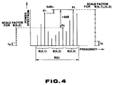
- An example of the case where a block B(k) corresponding to a single critical band is divided into three small blocks B(k,1), B(k,2) and B(k,3) is shown in Figure 4. In the example of Figure 4, a maximum one of the peak values P₁, P₂ and P₃ of respective small blocks B(k,1), B(k,2) and B(k,3) is taken as a peak value P₃. The peak value P₁ is assumed to have a difference less than 6 dB between the peak value P₁ and the peak value P₃, and the peak value P₂ is assumed to have a difference more than 6 dB between the peak value P₁ and the peak value P₃.
- In the example shown in Figure 4, respective spectrum data of small blocks B(k,1) and B(k,3) where the difference between respective peak values is less than 6 dB are quantized by a step size Δ₃ by using a greater peak value P₃ as a common scale factor. On the contrary, spectrum data in the small block B(k,2) is quantized by a step size Δ₂ by using the peak value P₂ as a scale factor. Thus, small blocks B(k,1) and B(k,3) are combined into a single block to carry out the floating processing on every single block. Further, the floating processing is carried out by using the small block B(k,2) as a single block.
- As stated above, when a single critical band is divided into three blocks or more, the approach employed is to determine the maximum one of peak values of these small blocks to allow small blocks where a difference between respective peak values is less than 6 dB to be a common block to carry out the block floating processing thereby to reduce the number of peak values, and independently to process small blocks where that difference is more than 6 dB thereby to prevent quantization noise from increasing.
- As an actual example of a coding apparatus for a digital signal, an embodiment of this invention will be described in connection with a coding apparatus using band divisional coding (SBC), adaptive transform coding (ATC) and adaptive bit allocation (APC-AB).
- In the coding apparatus shown in Figure 5, an input digital signal is divided into signal components in a plurality of frequency bands with the bandwidth becoming broader at higher frequencies, to carry out orthogonal transform processing on respective frequency bands adaptively to bit-allocate spectrum data on the frequency base thus obtained for every so-called critical band in which human hearing characteristics, which will be described later, are taken into consideration, to encode the data. Further, in this embodiment another scheme is also employed adaptively to vary the block size (block length) in dependence upon an input signal prior to orthogonal transform processing, and to carry out floating processing on every block.
- Thus, in Figure 5, an audio PCM signal, for example, of 0 to 20 KHz is supplied to the
input terminal 10. This input signal is divided into signal components in the frequency band of 0 to 10 KHz and the frequency band of 10 to 20 KHz by a band division filter 11, such as a so-called QMF filter. Further, the signal component in the frequency band of 0 to 10 KHz is divided into signal components in the frequency band of 0 to 5 KHz and the frequency band of 5 to 10 KHz by a similarband division filter 12 such as a QMF filter. The signal component in the frequency band of 10 to 20 KHz from the band division filter 11 is supplied to anorthogonal transform circuit 13; the signal component in the frequency band of 5 to 10 KHz from theband division filter 12 is supplied to theFFT circuit 14; and the signal component in the frequency band of 0 to 5 KHz is supplied to theFFT circuit 15, whereby those signal components are subjected to orthogonal transform processing. - An actual example of a standard input signal with respect to blocks of respective bands, which is supplied to the respective
orthogonal transform circuits input signal 0 to 22 KHz, the lower frequency band is in a range of 0 to 5.5 KHz, the medium frequency band is in a range of 5.5 to 11 KHz, and the higher frequency band is in a range of 11 to 22 KHz. - Turning back to Figure 5, spectrum data on the frequency base or orthogonal transform coefficient data provided as a result of orthogonal transform processing at respective
orthogonal transform circuits bit allocation encoder 18. This critical band is frequency band divided in dependence on human hearing wherein narrow band noise having the same intensity as that of a pure sound and existing in the vicinity of the pure sound masks the pure sound. These critical bands are such that as the frequency shifts to a higher frequency, the bandwidth becomes broader, and the entire frequency band of 0 to 20 KHz is divided into 25 critical bands. - An allowed
noise calculation circuit 20 determines, on the basis of spectrum data divided into critical bands, allowed noise quantities for each critical band in which the so-called masking effect, etc. is taken into consideration to determine, for each critical band, allocated bit numbers, on the basis of the allowed noise quantities and energies or peak values, etc. to requantize respective spectrum data (or orthogonal transform data) in dependence upon the number of bits allocated to respective critical bands by the adaptivebit allocation encoder 18. Data thus coded are derived at anoutput terminal 19. - In coding in the adaptive
bit allocation encoder 18, block floating processing is carried out on every critical band. Further, as explained above, a single critical band is divided into several small blocks to carry out block floating processing on every small block in dependence upon the tonality of an input signal, that is, when the difference between respective peak values of respective small blocks is more than 6 dB. Thus, quantization noise is avoided. - Figure 7 is a block circuit diagram of an actual example of the
noise calculation circuit 20. In Figure 7, spectrum data on the frequency base from the respectiveorthogonal transform circuits input terminal 21. As these data, only the amplitude value and the phase value calculated on the basis of the real number component and the imaginary number component of orthogonal transform coefficient data obtained by performing the orthogonal transform operation are used. This is because human hearing is more sensitive to the amplitude (level, intensity) on the frequency base, but considerably more sensitive to the phase. - The input data on the frequency base is supplied to an
energy calculation circuit 22, at which energies of each critical band are determined, for example, by calculating a sum total of respective amplitude values in the band. In place of energies of each respective band, peak values or mean values of amplitude value may be used. A spectrum of sum total of respective bands as an output from theenergy calculation circuit 22 is generally called a bark spectrum. Figure 8 shows such a bark spectrum SB for respective bands. It is to be noted that, in order to simplify Figure 8, only twelve critical bands are shown (B₁ to B₁₂). - To allow for the influence in the so-called masking of the bark spectrum SB, convolution processing is used to multiply respective values of the back spectrum SB by a predetermined weighting function to add the multiplied values. To realize this, an output from a
circuit 22 for calculating an energy every band, that is, respective values of the bark spectrum SB are supplied to aconvolution filter circuit 23. Thisconvolution filter circuit 23 comprises, for example, a plurality of delay elements for sequentially delaying input data, a plurality of multipliers (for example, 25 multipliers corresponding to respective bands) for multiplying outputs from these delay elements by filter coefficients (weighting function), and a sum total adder for taking a sum total of respective multiplier outputs. By this convolution processing, the sum total of the portion indicated by dotted lines in Figure 8 is derived. It is to be noted that the above-mentioned masking refers to the phenomenon that a signal is masked by another signal, and is not heard. As the masking effect, there are the simultaneous masking effect by a signal on the time base and the masking effect for an audio signal on the frequency base. Thus, due to masking effect, even if there is any noise at the portion subject to masking, such a noise will not be heard. For this reason, in an actual audio signal, noise in the portion subject to masking is considered as an allowable noise. - Referring to an example of multiplying coefficients (filter coefficients) of respective multipliers of the
convolution filter circuit 23, when the coefficient of a multiplier M corresponding to an arbitrary band is assumed to be one, at the multiplier M-1, the filter coefficient 0.15 is multiplied by outputs of respective delay elements; at the multiplier M-2 the filter coefficient 0.0019 is multiplied by those outputs; at the multiplier M-3, the filter coefficient 0.0000086 is multiplied by those outputs; at the multiplier M+1, the filter coefficient 0.4 is multiplied by those outputs; at the multiplier M+2, the filter coefficient 0.06 is multiplied by those outputs; and at the multiplier M+3, the filter coefficient 0.007 is multiplied by those outputs. Thus, convolution processing of the bark spectrum SB is carried out. It is to be noted that M is an arbitrary integer of one to 25. - Thereafter, an output of the
convolution filter circuit 23 is supplied to asubtracter 24 which serves to determine a level α corresponding to an allowable noise level, which will be described later, in the convoluted region. It is to be noted that the level α corresponding to the allowable noise level (allowed noise level) is a level to correspond with the allowed noise level in every band of the critical band when carrying out deconvolution processing as described later. Here, an allowed function (function representing the masking level) for determining the level α is supplied to thesubtracter 24. By increasing or decreasing this allowed function, control of the level α is carried out. This allowed function is supplied from a (n-ai)function generator 25 which will be described later. - When the number given in order from a lower frequency band of bands of the critical band is assumed to be i, the level of α corresponding to the allowed noise level is determined by the following equation:

where n and a are respective constants (a>0), and S is the intensity of a convolution processed bark spectrum. In the above equation (1), (n-ai) represents an allowed function. In this embodiment, n is set to 38 and a is set to 1. There then results no degradation of sound quality, and satisfactory coding is thus carried out. - In this way, the level α is determined. These data are transmitted to a
divider 26 which serves to apply deconvolution to the level α in the convolution region. Accordingly, by carrying out this deconvolution, a masking spectrum is provided from the level α. Namely, this masking spectrum becomes an allowed noise spectrum. It is to be noted that while the above-mentioned deconvolution processing requires a complicated operation, asimplified divider 26 is used in this embodiment to carry out deconvolution. - Then, the above-mentioned masking spectrum is transmitted to a
subtracter 28 through asynthesis circuit 27. Here, thesubtracter 28 through asynthesis circuit 27. Here, thesubtracter 28 through asynthesis circuit 27. Here, thesubtracter 28 is supplied with an output of theenergy detector 22 in every band, that is, the previously described bark spectrum SB through adelay circuit 29. Accordingly, at thissubtracter 28, a subtractive operation between the masking spectrum and the bark spectrum SB is carried out. Thus, as shown in Figure 12, the portion of the bark spectrum SB of which level is lower than the level indicated by the level of the masking spectrum MS is subjected to masking. - An output from the
subtracter 28 is taken out through an allowednoise corrector 30 and theoutput terminal 31, and is supplied to a ROM, etc. (not shown) at which, for example, allocated bit number information are stored. This ROM, etc. serves to supply allocated bit number information every band in dependence upon an output (difference level between energy of each band and an output of the noise level setting means) obtained through the allowednoise corrector 30 from thesubtracter 28. This allocated bit number information is supplied to the adaptivebit allocation encoder 18, whereby spectrum data on the frequency base from theDCT circuits - In short, the adaptive
bit allocation encoder 18 serves to quantize spectrum data in respective bands by bit numbers allocated in dependence upon levels of differences between energies of respective bands of the critical band and an output of the noise level setting means. It is to be noted that adelay circuit 29 is provided in order to delay the bark spectrum SB from theenergy detector 22 by taking into consideration delay quantities at respective circuits preceding thesynthesis circuit 27. - Meanwhile, in synthesis at the above-described
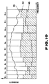
synthesis circuit 27, it is possible to synthesize data indicating the so-called minimum audible curve RC which is the human hearing characteristic as shown in Figure 13 supplied from a minimumaudible curve generator 32 and the above-mentioned masking spectrum MS. In this minimum audible curve, if the noise absolute level is below the minimum audible curve, this noise cannot be heard. Furthermore, even if coding is the same, the minimum audible curve would vary, for example, in dependence upon variation of a reproducing volume at the time of reproduction. However, it is to be noted that, since there is not so great a variation in the manner in which music enters, for example, a 16-bit dynamic range in actual digital systems, if it is assumed that quantization noise of, for example, the frequency band most easily heard in the vicinity of 4 KHz, quantization noise less than the level of the minimum audible curve is considered to be not heard in other frequency bands. Accordingly, noise in the vicinity of 4 KHz of a word length that the system has is not heard, and an allowed noise level is provided by synthesizing the minimum audible curve RC and the masking spectrum MS, the allowed noise level in this case is permitted to be the level up to the portion indicated by hatching in Figure 13. It is to be noted that, in this embodiment, the level of 4 KHz of the minimum audible curve is caused to correspond with the minimum level correspond to, for example, 20 bits. In Figure 13, signal spectrum SS is also shown. - At the allowed
noise level corrector 30, the allowed noise level in an output from thesubtracter 28 is corrected on the basis of a so-called equi-loudness curve supplied from a correctioninformation output circuit 33. The equi-loudness curve is related to the human hearing characteristics. This curve is obtained by determining sound pressures of sound at respective frequencies, which can be heard at the same intensity as that of a pure sound of, for example, 1 KHz. This curve is also called an equi-sensitivity curve of loudness. The equi-loudness curve is substantially the same as the minimum audible curve RC shown in Figure 10. In this equi-loudness curve, for example in the vicinity of 4 KHz, sound is heard at the same intensity as a sound at 1 KHz. In contrast, in the vicinity of 50 KHz, if the sound pressure is not higher than the sound pressure in the vicinity of 1 KHz by about 15 dB, the sound is not heard at the same intensity. For this reason, it is seen that it is desirable to allow noise above the level of the minimum audible curve (allowed noise level) to have a frequency characteristic given by a curve corresponding to the equi-lness curve. For this reason, it is seen that there is adaption for human hearing characteristics, to correct the allowed noise level by taking the equi-loudness curve into consideration.
- Here, as the correction
information output circuit 33, there may be employed a circuit to correct the allowed noise level on the basis of a detected output of output information (data quantity) quantized at theencoder 18, and a bit rate target value of the final coded data. The reason why such a correction is made is as follows. Since there are instances where the total bit number provided by carrying out in advance a temporary adaptive bit allocation with respect to all bit allocation unit blocks may have an error with respect to a fixed number of bits (target value) determined by the bit rate of the final coded output data, it is required to carry out bit allocation for a second time, so that the above error becomes equal to zero. When the total number of allocated bits is less than the target value, bit numbers of differences are allocated to respective unit blocks to increase that number. In contrast, when the total number of allocated bits is greater than the target value, bit numbers of differences are allocated to respective unit blocks to decrease that number. - To carry this out, the correction
information output circuit 33 outputs correction data for correcting respective allocated bit numbers in dependence upon detected data indicative of an error from the target value of the total number of allocated bits. Here, in the case where the error data indicates that the number of bits is insufficient, an increased number of bits per unit block is used, in consideration of the case where the data quantity is greater than the target value. Further, in the case where the error data are data indicating bit number remainder, it is sufficient that the number of bits per unit block is small, in consideration of the case where the data quantity is less than the target value. Accordingly, data of the correction value for correcting an allowed noise level in an output level from thesubtracter 28 on the basis of, for example, information data of the equi-loudness curve are outputted from the correctioninformation output circuit 33 in accordance with this error data. The correction value as described above is transmitted to the allowednoise corrector 30, whereby an allowed noise level from thesubtracter 28 is corrected. - It is to be noted that this invention is not limited to the above-described embodiment, and is applicable, for example, not only to a signal processor for an audio PCM signal, but also to a signal processor for a digital speech signal or a digital video signal, etc. Further, there may be employed a configuration such that the above-described synthesis processing of the minimum audible curve is not carried out. In this case, the minimum
audible curve generator 32 and thesynthesis circuit 27 are unnecessary, and an output from thesubtracter 24 is subjected to deconvolution at thesubtracter 26, and is then transmitted directly to thesubtracter 28.
Claims (7)
- A coding apparatus for a digital signal which divides an input digital signal into signal components in a plurality of bands of predetermined frequencies to carry out orthogonal transform on each divided band, signal components on the frequency base being divided into blocks in critical bands then to carry out floating processing thereof;
wherein said critical bands are further divided into small blocks to compare respective indices for the floating processing for each small block to carry out the floating processing when the compared difference is above a fixed value. - Apparatus according to claim 1 wherein when a difference between respective indices for the floating processing is within a fixed value, said small blocks are floating processed using a common index for the floating processing.
- Apparatus according to claim 1 wherein said floating processing is carried out by determining a maximum absolute value of all words of a digital signal within said respective small blocks to use said maximum absolute value as a floating coefficient common to all the words within said small blocks.
- Apparatus according to claim 3 wherein when a difference between respective maximum values of said these respective small blocks is more than 6 dB, the floating processing is carried out on each respective small block.
- Apparatus according to claim 3 wherein said floating processing includes requantization processing.
- Apparatus according to any one of the preceding claims wherein said orthogonal transform is fast Fourier transform.
- Apparatus according to any one of claims 1 to 5 wherein said orthogonal transform is discrete cosine transform.
Applications Claiming Priority (2)
| Application Number | Priority Date | Filing Date | Title |
|---|---|---|---|
| JP92738/91 | 1991-03-30 | ||
| JP03092738A JP3134337B2 (en) | 1991-03-30 | 1991-03-30 | Digital signal encoding method |
Publications (3)
| Publication Number | Publication Date |
|---|---|
| EP0507499A2 true EP0507499A2 (en) | 1992-10-07 |
| EP0507499A3 EP0507499A3 (en) | 1994-05-04 |
| EP0507499B1 EP0507499B1 (en) | 1998-05-20 |
Family
ID=14062763
Family Applications (1)
| Application Number | Title | Priority Date | Filing Date |
|---|---|---|---|
| EP92302617A Expired - Lifetime EP0507499B1 (en) | 1991-03-30 | 1992-03-26 | Orthogonal transform coding apparatus for digital audio signals |
Country Status (6)
| Country | Link |
|---|---|
| US (1) | US5264846A (en) |
| EP (1) | EP0507499B1 (en) |
| JP (1) | JP3134337B2 (en) |
| KR (1) | KR100279094B1 (en) |
| AT (1) | ATE166505T1 (en) |
| DE (1) | DE69225524T2 (en) |
Cited By (2)
| Publication number | Priority date | Publication date | Assignee | Title |
|---|---|---|---|---|
| EP0645769A2 (en) * | 1993-09-28 | 1995-03-29 | Sony Corporation | Signal encoding or decoding apparatus and recording medium |
| EP0669724A1 (en) * | 1993-07-16 | 1995-08-30 | Sony Corporation | High-efficiency encoding method, high-efficiency decoding method, high-efficiency encoding device, high-efficiency decoding device, high-efficiency encoding/decoding system and recording media |
Families Citing this family (60)
| Publication number | Priority date | Publication date | Assignee | Title |
|---|---|---|---|---|
| US5479562A (en) * | 1989-01-27 | 1995-12-26 | Dolby Laboratories Licensing Corporation | Method and apparatus for encoding and decoding audio information |
| US5115240A (en) * | 1989-09-26 | 1992-05-19 | Sony Corporation | Method and apparatus for encoding voice signals divided into a plurality of frequency bands |
| KR100268623B1 (en) * | 1991-06-28 | 2000-10-16 | 이데이 노부유끼 | Compressed data recording and/or reproducing apparatus and signal processing method |
| EP0525809B1 (en) * | 1991-08-02 | 2001-12-05 | Sony Corporation | Digital encoder with dynamic quantization bit allocation |
| DE69231369T2 (en) * | 1991-09-30 | 2001-03-29 | Sony Corp | Method and device for audio data compression |
| JP3153933B2 (en) * | 1992-06-16 | 2001-04-09 | ソニー株式会社 | Data encoding device and method and data decoding device and method |
| JP3189401B2 (en) * | 1992-07-29 | 2001-07-16 | ソニー株式会社 | Audio data encoding method and audio data encoding device |
| JPH06180948A (en) * | 1992-12-11 | 1994-06-28 | Sony Corp | Method and unit for processing digital signal and recording medium |
| JP3186292B2 (en) * | 1993-02-02 | 2001-07-11 | ソニー株式会社 | High efficiency coding method and apparatus |
| JP3150475B2 (en) * | 1993-02-19 | 2001-03-26 | 松下電器産業株式会社 | Quantization method |
| JP3123290B2 (en) * | 1993-03-09 | 2001-01-09 | ソニー株式会社 | Compressed data recording device and method, compressed data reproducing method, recording medium |
| JP3186307B2 (en) * | 1993-03-09 | 2001-07-11 | ソニー株式会社 | Compressed data recording apparatus and method |
| TW232116B (en) * | 1993-04-14 | 1994-10-11 | Sony Corp | Method or device and recording media for signal conversion |
| US5581654A (en) * | 1993-05-25 | 1996-12-03 | Sony Corporation | Method and apparatus for information encoding and decoding |
| KR100287494B1 (en) * | 1993-06-30 | 2001-04-16 | 이데이 노부유끼 | Digital signal encoding method and apparatus, decoding method and apparatus and recording medium of encoded signal |
| US5737720A (en) * | 1993-10-26 | 1998-04-07 | Sony Corporation | Low bit rate multichannel audio coding methods and apparatus using non-linear adaptive bit allocation |
| KR100330290B1 (en) * | 1993-11-04 | 2002-08-27 | 소니 가부시끼 가이샤 | Signal encoding device, signal decoding device, and signal encoding method |
| KR960003628B1 (en) * | 1993-12-06 | 1996-03-20 | Lg전자주식회사 | Coding and decoding apparatus & method of digital signal |
| US5731767A (en) * | 1994-02-04 | 1998-03-24 | Sony Corporation | Information encoding method and apparatus, information decoding method and apparatus, information recording medium, and information transmission method |
| US5608713A (en) * | 1994-02-09 | 1997-03-04 | Sony Corporation | Bit allocation of digital audio signal blocks by non-linear processing |
| JP3186412B2 (en) * | 1994-04-01 | 2001-07-11 | ソニー株式会社 | Information encoding method, information decoding method, and information transmission method |
| JP3277682B2 (en) * | 1994-04-22 | 2002-04-22 | ソニー株式会社 | Information encoding method and apparatus, information decoding method and apparatus, and information recording medium and information transmission method |
| JP3277699B2 (en) * | 1994-06-13 | 2002-04-22 | ソニー株式会社 | Signal encoding method and apparatus, and signal decoding method and apparatus |
| JP3250376B2 (en) * | 1994-06-13 | 2002-01-28 | ソニー株式会社 | Information encoding method and apparatus, and information decoding method and apparatus |
| TW295747B (en) * | 1994-06-13 | 1997-01-11 | Sony Co Ltd | |
| JP3277705B2 (en) | 1994-07-27 | 2002-04-22 | ソニー株式会社 | Information encoding apparatus and method, and information decoding apparatus and method |
| JP3341474B2 (en) * | 1994-07-28 | 2002-11-05 | ソニー株式会社 | Information encoding method and decoding method, information encoding device and decoding device, and information recording medium |
| JP2776277B2 (en) * | 1994-12-08 | 1998-07-16 | 日本電気株式会社 | Audio coding device |
| JP3557674B2 (en) * | 1994-12-15 | 2004-08-25 | ソニー株式会社 | High efficiency coding method and apparatus |
| JPH08190764A (en) * | 1995-01-05 | 1996-07-23 | Sony Corp | Method and device for processing digital signal and recording medium |
| US5699479A (en) * | 1995-02-06 | 1997-12-16 | Lucent Technologies Inc. | Tonality for perceptual audio compression based on loudness uncertainty |
| JPH08223049A (en) * | 1995-02-14 | 1996-08-30 | Sony Corp | Signal coding method and device, signal decoding method and device, information recording medium and information transmission method |
| JP3307138B2 (en) * | 1995-02-27 | 2002-07-24 | ソニー株式会社 | Signal encoding method and apparatus, and signal decoding method and apparatus |
| US5706392A (en) * | 1995-06-01 | 1998-01-06 | Rutgers, The State University Of New Jersey | Perceptual speech coder and method |
| US5960390A (en) * | 1995-10-05 | 1999-09-28 | Sony Corporation | Coding method for using multi channel audio signals |
| JP3189660B2 (en) | 1996-01-30 | 2001-07-16 | ソニー株式会社 | Signal encoding method |
| US5825320A (en) * | 1996-03-19 | 1998-10-20 | Sony Corporation | Gain control method for audio encoding device |
| JP3318825B2 (en) * | 1996-08-20 | 2002-08-26 | ソニー株式会社 | Digital signal encoding method, digital signal encoding device, digital signal recording method, digital signal recording device, recording medium, digital signal transmission method, and digital signal transmission device |
| JPH1083623A (en) * | 1996-09-10 | 1998-03-31 | Sony Corp | Signal recording method, signal recorder, recording medium and signal processing method |
| JP3496411B2 (en) * | 1996-10-30 | 2004-02-09 | ソニー株式会社 | Information encoding method and decoding device |
| TW384434B (en) | 1997-03-31 | 2000-03-11 | Sony Corp | Encoding method, device therefor, decoding method, device therefor and recording medium |
| JP3282661B2 (en) * | 1997-05-16 | 2002-05-20 | ソニー株式会社 | Signal processing apparatus and method |
| US6091773A (en) * | 1997-11-12 | 2000-07-18 | Sydorenko; Mark R. | Data compression method and apparatus |
| US6236766B1 (en) * | 1998-09-11 | 2001-05-22 | General Electric Company | Method and apparatus for zooming digital images |
| JP2000101439A (en) | 1998-09-24 | 2000-04-07 | Sony Corp | Information processing unit and its method, information recorder and its method, recording medium and providing medium |
| US6765930B1 (en) | 1998-12-11 | 2004-07-20 | Sony Corporation | Decoding apparatus and method, and providing medium |
| US6735561B1 (en) | 2000-03-29 | 2004-05-11 | At&T Corp. | Effective deployment of temporal noise shaping (TNS) filters |
| US7099830B1 (en) | 2000-03-29 | 2006-08-29 | At&T Corp. | Effective deployment of temporal noise shaping (TNS) filters |
| AUPR433901A0 (en) * | 2001-04-10 | 2001-05-17 | Lake Technology Limited | High frequency signal construction method |
| US7447631B2 (en) * | 2002-06-17 | 2008-11-04 | Dolby Laboratories Licensing Corporation | Audio coding system using spectral hole filling |
| JP3861770B2 (en) * | 2002-08-21 | 2006-12-20 | ソニー株式会社 | Signal encoding apparatus and method, signal decoding apparatus and method, program, and recording medium |
| US20050041757A1 (en) * | 2003-08-04 | 2005-02-24 | Lowell Rosen | Frequency-hopped holographic communications apparatus and methods |
| US10721405B2 (en) | 2004-03-25 | 2020-07-21 | Clear Imaging Research, Llc | Method and apparatus for implementing a digital graduated filter for an imaging apparatus |
| US9826159B2 (en) | 2004-03-25 | 2017-11-21 | Clear Imaging Research, Llc | Method and apparatus for implementing a digital graduated filter for an imaging apparatus |
| WO2005093654A2 (en) | 2004-03-25 | 2005-10-06 | Fatih Ozluturk | Method and apparatus to correct digital image blur due to motion of subject or imaging device |
| US20060034531A1 (en) * | 2004-05-10 | 2006-02-16 | Seiko Epson Corporation | Block noise level evaluation method for compressed images and control method of imaging device utilizing the evaluation method |
| TW200811204A (en) * | 2006-05-19 | 2008-03-01 | Nissan Chemical Ind Ltd | Hyper-branched polymer and process for producing the same |
| JP6179087B2 (en) * | 2012-10-24 | 2017-08-16 | 富士通株式会社 | Audio encoding apparatus, audio encoding method, and audio encoding computer program |
| JP6492915B2 (en) * | 2015-04-15 | 2019-04-03 | 富士通株式会社 | Encoding apparatus, encoding method, and program |
| KR101936744B1 (en) | 2015-12-23 | 2019-01-11 | 코웨이 주식회사 | Water discharging apparatus |
Citations (2)
| Publication number | Priority date | Publication date | Assignee | Title |
|---|---|---|---|---|
| EP0064119A2 (en) * | 1981-04-30 | 1982-11-10 | International Business Machines Corporation | Speech coding methods and apparatus for carrying out the method |
| EP0386418A2 (en) * | 1989-03-06 | 1990-09-12 | Robert Bosch Gmbh | Method for data reduction of digital audio signals and for approximate recovery of same |
Family Cites Families (5)
| Publication number | Priority date | Publication date | Assignee | Title |
|---|---|---|---|---|
| NL8700985A (en) * | 1987-04-27 | 1988-11-16 | Philips Nv | SYSTEM FOR SUB-BAND CODING OF A DIGITAL AUDIO SIGNAL. |
| US5109417A (en) * | 1989-01-27 | 1992-04-28 | Dolby Laboratories Licensing Corporation | Low bit rate transform coder, decoder, and encoder/decoder for high-quality audio |
| US5142656A (en) * | 1989-01-27 | 1992-08-25 | Dolby Laboratories Licensing Corporation | Low bit rate transform coder, decoder, and encoder/decoder for high-quality audio |
| US5115240A (en) * | 1989-09-26 | 1992-05-19 | Sony Corporation | Method and apparatus for encoding voice signals divided into a plurality of frequency bands |
| JPH03117919A (en) * | 1989-09-30 | 1991-05-20 | Sony Corp | Digital signal encoding device |
-
1991
- 1991-03-30 JP JP03092738A patent/JP3134337B2/en not_active Expired - Lifetime
-
1992
- 1992-03-25 KR KR1019920004795A patent/KR100279094B1/en not_active IP Right Cessation
- 1992-03-26 AT AT92302617T patent/ATE166505T1/en active
- 1992-03-26 EP EP92302617A patent/EP0507499B1/en not_active Expired - Lifetime
- 1992-03-26 DE DE69225524T patent/DE69225524T2/en not_active Expired - Lifetime
- 1992-03-27 US US07/859,116 patent/US5264846A/en not_active Expired - Lifetime
Patent Citations (2)
| Publication number | Priority date | Publication date | Assignee | Title |
|---|---|---|---|---|
| EP0064119A2 (en) * | 1981-04-30 | 1982-11-10 | International Business Machines Corporation | Speech coding methods and apparatus for carrying out the method |
| EP0386418A2 (en) * | 1989-03-06 | 1990-09-12 | Robert Bosch Gmbh | Method for data reduction of digital audio signals and for approximate recovery of same |
Cited By (5)
| Publication number | Priority date | Publication date | Assignee | Title |
|---|---|---|---|---|
| EP0669724A1 (en) * | 1993-07-16 | 1995-08-30 | Sony Corporation | High-efficiency encoding method, high-efficiency decoding method, high-efficiency encoding device, high-efficiency decoding device, high-efficiency encoding/decoding system and recording media |
| EP0669724A4 (en) * | 1993-07-16 | 1998-09-16 | Sony Corp | High-efficiency encoding method, high-efficiency decoding method, high-efficiency encoding device, high-efficiency decoding device, high-efficiency encoding/decoding system and recording media. |
| US6104321A (en) * | 1993-07-16 | 2000-08-15 | Sony Corporation | Efficient encoding method, efficient code decoding method, efficient code encoding apparatus, efficient code decoding apparatus, efficient encoding/decoding system, and recording media |
| EP0645769A2 (en) * | 1993-09-28 | 1995-03-29 | Sony Corporation | Signal encoding or decoding apparatus and recording medium |
| EP0645769A3 (en) * | 1993-09-28 | 2000-01-19 | Sony Corporation | Signal encoding or decoding apparatus and recording medium |
Also Published As
| Publication number | Publication date |
|---|---|
| US5264846A (en) | 1993-11-23 |
| KR920019109A (en) | 1992-10-22 |
| ATE166505T1 (en) | 1998-06-15 |
| EP0507499B1 (en) | 1998-05-20 |
| DE69225524D1 (en) | 1998-06-25 |
| EP0507499A3 (en) | 1994-05-04 |
| KR100279094B1 (en) | 2001-01-15 |
| JPH04304031A (en) | 1992-10-27 |
| JP3134337B2 (en) | 2001-02-13 |
| DE69225524T2 (en) | 1998-09-17 |
Similar Documents
| Publication | Publication Date | Title |
|---|---|---|
| EP0507499B1 (en) | Orthogonal transform coding apparatus for digital audio signals | |
| US5490170A (en) | Coding apparatus for digital signal | |
| US5268685A (en) | Apparatus with transient-dependent bit allocation for compressing a digital signal | |
| US5311561A (en) | Method and apparatus for compressing a digital input signal with block floating applied to blocks corresponding to fractions of a critical band or to multiple critical bands | |
| EP0473367B1 (en) | Digital signal encoders | |
| US5294925A (en) | Data compressing and expanding apparatus with time domain and frequency domain block floating | |
| US5381143A (en) | Digital signal coding/decoding apparatus, digital signal coding apparatus, and digital signal decoding apparatus | |
| EP0535889B1 (en) | Method and apparatus for audio data compression | |
| US5414795A (en) | High efficiency digital data encoding and decoding apparatus | |
| US5454011A (en) | Apparatus and method for orthogonally transforming a digital information signal with scale down to prevent processing overflow | |
| US5583967A (en) | Apparatus for compressing a digital input signal with signal spectrum-dependent and noise spectrum-dependent quantizing bit allocation | |
| EP0772925B1 (en) | Non-linearly quantizing an information signal | |
| JP3041967B2 (en) | Digital signal coding device | |
| JP3070123B2 (en) | Digital signal encoding apparatus and method | |
| JP3060578B2 (en) | Digital signal encoding method | |
| JP3132031B2 (en) | High-efficiency coding of digital signals. | |
| JP3134335B2 (en) | Digital signal encoding method and digital signal decoding device | |
| EP1176743A2 (en) | Methods for non-linearly quantizing and dequantizing an information signal | |
| JPH04302538A (en) | Digital signal encoding device | |
| JPH04302534A (en) | Digital signal encoding method |
Legal Events
| Date | Code | Title | Description |
|---|---|---|---|
| PUAI | Public reference made under article 153(3) epc to a published international application that has entered the european phase |
Free format text: ORIGINAL CODE: 0009012 |
|
| AK | Designated contracting states |
Kind code of ref document: A2 Designated state(s): AT DE FR GB IT NL |
|
| PUAL | Search report despatched |
Free format text: ORIGINAL CODE: 0009013 |
|
| AK | Designated contracting states |
Kind code of ref document: A3 Designated state(s): AT DE FR GB IT NL |
|
| 17P | Request for examination filed |
Effective date: 19941007 |
|
| 17Q | First examination report despatched |
Effective date: 19960917 |
|
| GRAG | Despatch of communication of intention to grant |
Free format text: ORIGINAL CODE: EPIDOS AGRA |
|
| GRAG | Despatch of communication of intention to grant |
Free format text: ORIGINAL CODE: EPIDOS AGRA |
|
| GRAH | Despatch of communication of intention to grant a patent |
Free format text: ORIGINAL CODE: EPIDOS IGRA |
|
| GRAH | Despatch of communication of intention to grant a patent |
Free format text: ORIGINAL CODE: EPIDOS IGRA |
|
| GRAA | (expected) grant |
Free format text: ORIGINAL CODE: 0009210 |
|
| AK | Designated contracting states |
Kind code of ref document: B1 Designated state(s): AT DE FR GB IT NL |
|
| REF | Corresponds to: |
Ref document number: 166505 Country of ref document: AT Date of ref document: 19980615 Kind code of ref document: T |
|
| REF | Corresponds to: |
Ref document number: 69225524 Country of ref document: DE Date of ref document: 19980625 |
|
| ITF | It: translation for a ep patent filed |
Owner name: SOCIETA' ITALIANA BREVETTI S.P.A. |
|
| ET | Fr: translation filed | ||
| PLBE | No opposition filed within time limit |
Free format text: ORIGINAL CODE: 0009261 |
|
| STAA | Information on the status of an ep patent application or granted ep patent |
Free format text: STATUS: NO OPPOSITION FILED WITHIN TIME LIMIT |
|
| 26N | No opposition filed | ||
| REG | Reference to a national code |
Ref country code: GB Ref legal event code: IF02 |
|
| REG | Reference to a national code |
Ref country code: FR Ref legal event code: RN |
|
| PGFP | Annual fee paid to national office [announced via postgrant information from national office to epo] |
Ref country code: FR Payment date: 20110404 Year of fee payment: 20 Ref country code: NL Payment date: 20110316 Year of fee payment: 20 Ref country code: AT Payment date: 20110314 Year of fee payment: 20 |
|
| PGFP | Annual fee paid to national office [announced via postgrant information from national office to epo] |
Ref country code: DE Payment date: 20110325 Year of fee payment: 20 Ref country code: GB Payment date: 20110321 Year of fee payment: 20 |
|
| PGFP | Annual fee paid to national office [announced via postgrant information from national office to epo] |
Ref country code: IT Payment date: 20110329 Year of fee payment: 20 |
|
| REG | Reference to a national code |
Ref country code: DE Ref legal event code: R071 Ref document number: 69225524 Country of ref document: DE |
|
| REG | Reference to a national code |
Ref country code: DE Ref legal event code: R071 Ref document number: 69225524 Country of ref document: DE |
|
| REG | Reference to a national code |
Ref country code: NL Ref legal event code: V4 Effective date: 20120326 |
|
| REG | Reference to a national code |
Ref country code: GB Ref legal event code: PE20 Expiry date: 20120325 |
|
| PG25 | Lapsed in a contracting state [announced via postgrant information from national office to epo] |
Ref country code: DE Free format text: LAPSE BECAUSE OF EXPIRATION OF PROTECTION Effective date: 20120327 |
|
| PG25 | Lapsed in a contracting state [announced via postgrant information from national office to epo] |
Ref country code: GB Free format text: LAPSE BECAUSE OF EXPIRATION OF PROTECTION Effective date: 20120325 |
|
| REG | Reference to a national code |
Ref country code: AT Ref legal event code: MK07 Ref document number: 166505 Country of ref document: AT Kind code of ref document: T Effective date: 20120326 |