EP0505333A2 - Estimating the charge of batteries - Google Patents
Estimating the charge of batteries Download PDFInfo
- Publication number
- EP0505333A2 EP0505333A2 EP92830128A EP92830128A EP0505333A2 EP 0505333 A2 EP0505333 A2 EP 0505333A2 EP 92830128 A EP92830128 A EP 92830128A EP 92830128 A EP92830128 A EP 92830128A EP 0505333 A2 EP0505333 A2 EP 0505333A2
- Authority
- EP
- European Patent Office
- Prior art keywords
- battery
- charge
- storage battery
- estimating
- model
- Prior art date
- Legal status (The legal status is an assumption and is not a legal conclusion. Google has not performed a legal analysis and makes no representation as to the accuracy of the status listed.)
- Granted
Links
Images


Classifications
-
- G—PHYSICS
- G01—MEASURING; TESTING
- G01R—MEASURING ELECTRIC VARIABLES; MEASURING MAGNETIC VARIABLES
- G01R31/00—Arrangements for testing electric properties; Arrangements for locating electric faults; Arrangements for electrical testing characterised by what is being tested not provided for elsewhere
- G01R31/36—Arrangements for testing, measuring or monitoring the electrical condition of accumulators or electric batteries, e.g. capacity or state of charge [SoC]
- G01R31/367—Software therefor, e.g. for battery testing using modelling or look-up tables
-
- G—PHYSICS
- G01—MEASURING; TESTING
- G01R—MEASURING ELECTRIC VARIABLES; MEASURING MAGNETIC VARIABLES
- G01R31/00—Arrangements for testing electric properties; Arrangements for locating electric faults; Arrangements for electrical testing characterised by what is being tested not provided for elsewhere
- G01R31/36—Arrangements for testing, measuring or monitoring the electrical condition of accumulators or electric batteries, e.g. capacity or state of charge [SoC]
- G01R31/382—Arrangements for monitoring battery or accumulator variables, e.g. SoC
- G01R31/3842—Arrangements for monitoring battery or accumulator variables, e.g. SoC combining voltage and current measurements
Definitions
- the present invention relates to an electronic apparatus for estimating the charge of lead storage batteries based upon the direct measurement of some parameters and the use thereof in a suitably arranged mathematical model.
- the invention relates also to a method of estimating the charge of storage batteries.
- the invention is aiming at providing an apparatus of the above mentioned kind which is adapted to improve the control of electrochemical storage battery systems in all major applications, and in particular the electrical drive systems, electrical networks (load balancing) and photovoltaic and aeolian systems.
- An accurate estimate of the battery charge can allow a more economical and effective use of the battery capacity and provide for a clear indication about the battery employment and recharge.
- the conventional methods are based upon measurements or calculations of the electrolyte density, open-circuit voltage, internal resistance, refractive index, relative humidity of the electrolyte, delivered charge (amperometric method), charging voltage and derivative of the voltage. Tipically, the precision of such known devices seldom is lower than 10% and the use thereof is complex and has a restricted application.
- the measurement of the density and the refractive index of the electrolyte can be carried out only for free-acid lead batteries and are complex and dangerous because they sometimes need intrusive sensors as well as balance conditions not suitable for real time estimates; moreover such methods do not allow for the variations due to the ageing of the storage battery. Similar limits can be found in the measurement of internal resistance and open-circuit voltage.
- the amperometric method, the measurement of the charging voltage and the derivative of the voltage are greatly restricted by the discharge conditions so that they are inaccurate in those applications where the variation of the discharge current is considerable. Also such methods hardly fits for the ageing of the storage battery.
- Algebraic methods are rather inaccurate while the dynamic method integrating the measured battery current requires a periodic zero setting of the estimated battery charge in order to avoid long range errors; moreover the estimated battery charge is very sensitive to the errors in the current measurements.
- the present invention carries out the estimate of the battery charge by means of a more sophisticated dynamic method which does not need any zero setting and is less sensitive to the errors in the current measurements.
- the apparatus of the invention is based upon a mathematical model simulating an equivalent network of a lead acid battery during the charging and discharging steps. By only directly measuring battery current and voltage and room temperature the apparatus allows the battery charge to be exactly measured and offers the possibility of performing a control function.
- a peculiar feature of the apparatus is that the storage battery is on-line arranged and the mathematical model fits the real state of the, storage battery even during the operating life thereof. Furthermore, the model conveniently follows both the charging and the discharging step, thus allowing also for the gas evolution step.
- Such apparatus of the "autoadaptive" type also permits all operating conditions to be. corrected and controlled at any time during the operating life of the storage battery, thus holding the precision of the charge measurement steady also by virtue of suitable error correction sequences regarding one or more significant quantities (voltage, temperature, current).
- the apparatus according to the invention essentially includes:
- FIG. 4 A preferred embodiment of the above mentioned apparatus is schematically shown in Fig. 4.
- battery current sensors, battery voltage sensors and room temperature seniors are designated by 1, 2 and 3, respectively.
- a multiplexer connected upstream of analog-to-digital converter 5 of the measured quantities is designated by 4.
- microprocessor 6 processes the signals of the basis of the estimate program stored in RAMs and ROMs 8 and transmits the estimated values to a digital display 9 and/or to an output 10 available for control devices.
- System clock is indicated at 7.
- the battery charge estimate apparatus has been developed on the basis of the battery model shown in the equivalent electricl diagram of Fig. 2.
- the equivalent electrical network consists of two main branches:
- Fig. 2 The components of Fig. 2 are designed considering the influence of the temperature and the age of the battery. Furthermore the thermal balance does not allow for the thermodynamic contribution of the reactions during the charbing and discharging steps which is much lower than the Joule effect losses.
- the storage battery is an electrical dipole, it can be transformed into a non-linear dynamic system model having a current as input signal and a voltage as output signal.
- the state variables of such system can be selected as follows:
- Id(A) and Iw(A) "charge transfer” current and "diffusion” current, respectively.
- the battery model can be expressed by the following equations:
- Fig. 1 The operation of the storage battery charge estimate apparatus according to the invention is schematically shown in Fig. 1.
- the dynamic model of the storage battery is activated by the battery input current and requires only the measurements of battery voltage and room temperature. With a perfect model and appropriate initial values of the battery charge there is no error in the charge estimate. However, the unavoidable errors in the model and in the initial charge values will cause an unforeseenable error in the estimated charge Q.
- the dynamic behavioral model is corrected according to the invention by the negative feedback of the differential error between the measured voltage and the estimated voltage.
- the error amount is due to a wrong value of the initial charge causing an error in the output voltage of the model, the model paramaters being estimated by a separate process. Therefore, the voltage error is used for modifying directly the derivative of the model's charge. In this way the estimated charge converges asymptotically to the value which cause the voltage error to tend to zero.
- Fig. 3 shows the complete block diagram of the battery charge estimate apparatus where both the measured quantities and the estimated quantities in the process are emphasized.
- the dashed blocks represent respectively:
- FIG. 6 The diagram of a photovoltaic system with storage batteries is shown in Fig. 6 where the photovoltaic panels are indicated at 12, the panel connection and disconnection system at 14, the storage batteries at 16, the load connection and disconnection system at 18, and the load at 20.
- the apparatus according to the invention is schematically formed by the components contained in the blocks surrounded by dashed lines.
- Said apparatus includes:
- the apparatus continuously measures the electrical characteristics of the storage batteries, voltage and current, and room temperature.
- the other three current values in the branch point allow the diagnostic about the correct operation of the data collection system to be provided.
- Data collection unit 24 is the interface between the outer sensors placed on the photovoltaic system and processing unit 26. All of measurement channels have a precision amplifier and a linear optical decoupler connected to an A/D converter. The amplifier allows the input signal. to be calibrated and adapted to the conversion range of the control system.
- the earthing elements of the control system and those of the whole system are galvanically separated by an optical decoupling device in order to prevent any disturbance.
- Calculation and control unit 26 based upon a microprocessor system compatible with MS-DOS environment (in this example a microprocessor INTEL 8088 with clock at 4,77 MHz and 512 kB memory is used) performs the function of controlling the whole system based upon the determined quantities, thus always supplying the load with the prefixed power, using the maximum power delivered by the photovoltaic generator, and never causing the battery to discharge under a predetermined level so as not to reduce the useful life thereof.
- a microprocessor system compatible with MS-DOS environment in this example a microprocessor INTEL 8088 with clock at 4,77 MHz and 512 kB memory is used
- the apparatus In the operation of the system the apparatus according to the invention operates on the basis of the block diagram of Fig. 7.
- block 1 delimited by dashed lines corresponds to the battery charge estimate apparatus, and block 2 to the control logic of the photovoltaic system
- ⁇ is the discharge rating of the battery
- ⁇ and ⁇ max are the limits of the discharge rating
- strip PV indicates a connectable or disconnectable photovoltaic panel
- P PV is the power generated by the photovoltaic system.
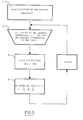
- the estimate of the storage battery charge is carried out by integrating differential equations as shown in the flow diagram of Fig. 5.
- the identification of the battery parameters which is the first step, is carried out off-line by dynamic and discharge tests before starting the system. The parameters can be calculated again during the maintenance periods of the system in which the estimate apparatus is connected.
- Second step quantities V, I measured at the battery terminals, and room temperature are sampled with a sampling time T sufficient for the microprocessor to carry out the estimate.
- Third step calculation of the error between measured voltage V and estimated voltage V ⁇ . If a measurement of the electrolyte temperature is available, also the error between measured electrolyte temperature O and estimated electrolyte temperature ⁇ can be calculated.
- Fourth step integration of the model equations by introducing a corrective factor depending on the previously calculated error.
- Such corrective factor increases or decreases current I p flowing along the active branch of the battery model.
- Quantities V ⁇ , ⁇ , Q ⁇ at time t + T are thus estimated.
- the apparatus of the present invention operates so as to disconnect the loads, to choke the power supply, and under limit conditions (too much discharged battery) to break the power supply.
- this invention can be used both in moving and stationary applications where lead storage batteries are employed. It can be particularly useful in the electrical traction, in systems with power sources which can be restored, and in electrical network load equalizing; in fact the invention allows the design, the management, and the use of the storage battery subsystem and the whole system to be optimized with considerable energetic, economical advantages.
Abstract
Description
- The present invention relates to an electronic apparatus for estimating the charge of lead storage batteries based upon the direct measurement of some parameters and the use thereof in a suitably arranged mathematical model. The invention relates also to a method of estimating the charge of storage batteries.
- The invention is aiming at providing an apparatus of the above mentioned kind which is adapted to improve the control of electrochemical storage battery systems in all major applications, and in particular the electrical drive systems, electrical networks (load balancing) and photovoltaic and aeolian systems.
- Performance, cost and reliability of electrical vehicles, photovoltaic and aeolian systems, and in general storage battery systems depend upon the capability of controlling the electrical storage batteries.
- An accurate estimate of the battery charge can allow a more economical and effective use of the battery capacity and provide for a clear indication about the battery employment and recharge.
- A lot of battery charge indicators have been proposed and manufactured especially for lead batteries which are the most used. The variety of such designed devices is also the result of the difficulty of exactly estimating the battery charge of an electrochemical storage battery due to the influence of several parameters such as discharge conditions, temperature, ageing, construction technology, and so on.
- At the present state of art the conventional methods are based upon measurements or calculations of the electrolyte density, open-circuit voltage, internal resistance, refractive index, relative humidity of the electrolyte, delivered charge (amperometric method), charging voltage and derivative of the voltage. Tipically, the precision of such known devices seldom is lower than 10% and the use thereof is complex and has a restricted application.
- The measurement of the density and the refractive index of the electrolyte can be carried out only for free-acid lead batteries and are complex and dangerous because they sometimes need intrusive sensors as well as balance conditions not suitable for real time estimates; moreover such methods do not allow for the variations due to the ageing of the storage battery. Similar limits can be found in the measurement of internal resistance and open-circuit voltage.
- The amperometric method, the measurement of the charging voltage and the derivative of the voltage are greatly restricted by the discharge conditions so that they are inaccurate in those applications where the variation of the discharge current is considerable. Also such methods hardly fits for the ageing of the storage battery.
- In order to overcome such problems battery charge indicators have been provided for some time which make use of analog circuits and calculate the battery charge on the basis of complex correlations among main parameters through linear and differential equations.
- The used methods are essentially of two types: algebraic and dynamic. Algebraic methods are rather inaccurate while the dynamic method integrating the measured battery current requires a periodic zero setting of the estimated battery charge in order to avoid long range errors; moreover the estimated battery charge is very sensitive to the errors in the current measurements.
- The present invention carries out the estimate of the battery charge by means of a more sophisticated dynamic method which does not need any zero setting and is less sensitive to the errors in the current measurements.
- The apparatus of the invention is based upon a mathematical model simulating an equivalent network of a lead acid battery during the charging and discharging steps. By only directly measuring battery current and voltage and room temperature the apparatus allows the battery charge to be exactly measured and offers the possibility of performing a control function.
- A peculiar feature of the apparatus is that the storage battery is on-line arranged and the mathematical model fits the real state of the, storage battery even during the operating life thereof. Furthermore, the model conveniently follows both the charging and the discharging step, thus allowing also for the gas evolution step.
- Such apparatus of the "autoadaptive" type also permits all operating conditions to be. corrected and controlled at any time during the operating life of the storage battery, thus holding the precision of the charge measurement steady also by virtue of suitable error correction sequences regarding one or more significant quantities (voltage, temperature, current).
- The invention will now be described with reference to the accompanying drawings showing by way of an illustrative, non-limitative example a preferred embodiment of the invention.
- In the drawings:
- Fig. 1 is a block diagram of the operating principle of the storage battery charge estimating apparatus according the the invention;
- Fig. 2 shows the equivalent electrical diagram of a lead storage battery according to the employed model;
- Fig. 3 is the complete block diagram of the battery charge estimating apparatus showing both the measured and the estimated quantities in the process;
- Fig. 4 is a block diagram of an embodiment of the apparatus;
- Fig. 5 shows the flow diagram of the mathematical model for the battery parameters and charge estimate;
- Fig. 6 shows the application of the apparatus to a photovoltaic system; and
- Fig. 7 is the flow diagram of the operation of the calculation and control unit of Fig. 6.
- The apparatus according to the invention essentially includes:
- a) transducers for measuring battery current and voltage and the temperature of the room where the storage battery is placed;
- b) a conditioning and analog-to-digital conversion system for the signals of said sensors;
- c) a microprocessor system processing the signals of a) and b) by the computer program of the following item e);
- d) a power supply for systems b) and c) formed of a power conditioner supplied in turn by the storage battery; and
- e) a program for processing data signals of items a) and b) which can provide:
- 1.- estimate of the storage battery charge and the internal temperature of the storage battery;
- 2.- estimate of the storage battery "life" condition;
- 3.- estimate of the electrolyte level in those storage batteries where the electrolyte is consumed due to secondary (parasitic) reactions;
- 4.- signal information for controlling the power supply of d) above;
- 5.- signal information for controlling any power conditioners such as battery chargers, controlled rectifiers, choppers, inverters and so on;
- 6.- signal information about any failured element of the storage battery.
- A preferred embodiment of the above mentioned apparatus is schematically shown in Fig. 4. In such figure battery current sensors, battery voltage sensors and room temperature seniors are designated by 1, 2 and 3, respectively. A multiplexer connected upstream of analog-to-
digital converter 5 of the measured quantities is designated by 4. Such quantities are fed tomicroprocessor 6 which processes the signals of the basis of the estimate program stored in RAMs andROMs 8 and transmits the estimated values to adigital display 9 and/or to anoutput 10 available for control devices. System clock is indicated at 7. - The battery charge estimate apparatus has been developed on the basis of the battery model shown in the equivalent electricl diagram of Fig. 2.
- The equivalent electrical network consists of two main branches:
- a primary branch (P) representing the main reversible oxidation-reduction reaction during the charging-discharging steps;
- a secondary branch (S) representing the irreversible parasitic reactions (the most important is the water electrolysis) causing the losses during the charging step.
- The components of Fig. 2 are designed considering the influence of the temperature and the age of the battery. Furthermore the thermal balance does not allow for the thermodynamic contribution of the reactions during the charbing and discharging steps which is much lower than the Joule effect losses.
- As the storage battery is an electrical dipole, it can be transformed into a non-linear dynamic system model having a current as input signal and a voltage as output signal.
- The state variables of such system can be selected as follows:
- Q (Ah): extracted electrical charge (which is the charge necessary to completely recharge the battery);
- δϑ (°C): difference between electrolyte and room temperatures;
- Id(A) and Iw(A): "charge transfer" current and "diffusion" current, respectively.
- With reference to such state variables and the network shown in Fig. 2 the battery model can be expressed by the following equations:

- The operation of the storage battery charge estimate apparatus according to the invention is schematically shown in Fig. 1.
- The dynamic model of the storage battery is activated by the battery input current and requires only the measurements of battery voltage and room temperature. With a perfect model and appropriate initial values of the battery charge there is no error in the charge estimate. However, the unavoidable errors in the model and in the initial charge values will cause an unforeseenable error in the estimated charge Q.
- In order to limit such errors the dynamic behavioral model is corrected according to the invention by the negative feedback of the differential error between the measured voltage and the estimated voltage. The error amount is due to a wrong value of the initial charge causing an error in the output voltage of the model, the model paramaters being estimated by a separate process. Therefore, the voltage error is used for modifying directly the derivative of the model's charge. In this way the estimated charge converges asymptotically to the value which cause the voltage error to tend to zero.
- Fig. 3 shows the complete block diagram of the battery charge estimate apparatus where both the measured quantities and the estimated quantities in the process are emphasized. The dashed blocks represent respectively:
- block A: measurement and analog-to-digital system;
- block B: off-line battery parameter measurement system;
- block C: battery charge estimate system allowing for voltage error;
- block D: integration of the dynamic equations allowing for the capacities of the battery model and the thermal equation;
- block E: output of the estimated quantities; where:
Td = fast time constant of the electrical dynamics of the battery; - Tw = slow time constant of the electrical dynamics of the battery;
T = thermal time constant;
GS(V,ϑ) is the conductance. of the passive branch;
Rp (Q, ϑ) is the ohmic resistance of the active branch;
Rd(Q, Id, ϑ) is the diffusion resistence;
Rw (Q, Iw, ϑ) is the polarizartion resistance. - 1) the measurement of the battery voltage is the only simple measurement allowing an error reaction; it is carried out an adjustment of the battery charge derivative because it is not available any information about errors regarding other quantities. In order to improve the accuracy of the battery charge estimate apparatus further measurements should be carried out: for example, a second error reaction can be actuated by a measurement of the electrolyte temperature. Of course, the more information is available, the greater is the accuracy of the estimated values.
- 2) as for the selection of the error gain a compromise between the accuracy of the apparatus and the response rate thereof should be accepted; the greater is the gain, the higher is the response rate but also the bigger is the error in the estimated values.
- By way of example an experimentally tested operation of the apparatus according to a feasible arrangement with TTL technology will now be explained with regard to measurement and control functions in a photovoltaic system based upon the equivalent electrical diagram of Fig. 2.
- The diagram of a photovoltaic system with storage batteries is shown in Fig. 6 where the photovoltaic panels are indicated at 12, the panel connection and disconnection system at 14, the storage batteries at 16, the load connection and disconnection system at 18, and the load at 20.
- The apparatus according to the invention is schematically formed by the components contained in the blocks surrounded by dashed lines. Said apparatus includes:
- a power supply unit 22 (ac/dc converter connected to the storage battery);
- a
data collection unit 24 detecting by not particularly sophisticated sensors currents, voltages and temperatures (six quantities as a whole); - a data processing and control unit (micro-processor) 26 which is adapted to control both the electric energy (in this case it chokes the output of the photovoltaic field by controlling choppers and relays) and the user by connecting and disconnecting several loads according to different priorities.
- In the operation the apparatus continuously measures the electrical characteristics of the storage batteries, voltage and current, and room temperature. The other three current values in the branch point (load current, photovoltaic current, and insolation) allow the diagnostic about the correct operation of the data collection system to be provided.
-
Data collection unit 24 is the interface between the outer sensors placed on the photovoltaic system andprocessing unit 26. All of measurement channels have a precision amplifier and a linear optical decoupler connected to an A/D converter. The amplifier allows the input signal. to be calibrated and adapted to the conversion range of the control system. - The earthing elements of the control system and those of the whole system are galvanically separated by an optical decoupling device in order to prevent any disturbance.
- Calculation and
control unit 26 based upon a microprocessor system compatible with MS-DOS environment (in this example a microprocessor INTEL 8088 with clock at 4,77 MHz and 512 kB memory is used) performs the function of controlling the whole system based upon the determined quantities, thus always supplying the load with the prefixed power, using the maximum power delivered by the photovoltaic generator, and never causing the battery to discharge under a predetermined level so as not to reduce the useful life thereof. - In the operation of the system the apparatus according to the invention operates on the basis of the block diagram of Fig. 7. In such figure, block 1 delimited by dashed lines corresponds to the battery charge estimate apparatus, and block 2 to the control logic of the photovoltaic system; ρ is the discharge rating of the battery, ρ , and ρmax are the limits of the discharge rating; strip PV indicates a connectable or disconnectable photovoltaic panel, PPV is the power generated by the photovoltaic system. After having initialized the input parameters of the storage battery model the apparatus starts the readout of the storage battery model as well as the relative quantities and converts the system measurement values by the A/D converter. Data is fed into the computer program relative to the battery charge and the other parameters of the lead storage battery. The estimate of the storage battery charge is carried out by integrating differential equations as shown in the flow diagram of Fig. 5. Referring to such diagram it should be noted that the identification of the battery parameters, which is the first step, is carried out off-line by dynamic and discharge tests before starting the system. The parameters can be calculated again during the maintenance periods of the system in which the estimate apparatus is connected.
- Second step: quantities V, I measured at the battery terminals, and room temperature are sampled with a sampling time T sufficient for the microprocessor to carry out the estimate.
- Third step: calculation of the error between measured voltage V and estimated voltage V̂. If a measurement of the electrolyte temperature is available, also the error between measured electrolyte temperature O and estimated electrolyte temperature Ô can be calculated.
- Fourth step: integration of the model equations by introducing a corrective factor depending on the previously calculated error. Such corrective factor increases or decreases current Ip flowing along the active branch of the battery model. Quantities V̂, Ô, Q̂ at time t + T are thus estimated.
- Fifth step: measurement and calculation cycle is started again at time t = t + T.
- Once the storage battery charge is estimated on the basis of intially predetermined conditions relative to the minimum and the maximum charge, to the priority of the several loads, and to the optimum working point of the various subsystems, the apparatus of the present invention operates so as to disconnect the loads, to choke the power supply, and under limit conditions (too much discharged battery) to break the power supply.
- In this specific case the use of the storage batteries as well as the whole efficiency of the system have been improved, and a battery charge estimate error of about 3% has been provided, which could not be achieved by the known systems.
- As mentioned above, this invention can be used both in moving and stationary applications where lead storage batteries are employed. It can be particularly useful in the electrical traction, in systems with power sources which can be restored, and in electrical network load equalizing; in fact the invention allows the design, the management, and the use of the storage battery subsystem and the whole system to be optimized with considerable energetic, economical advantages.
- The present invention has been illustrated and described according to a preferred embodiment thereof, however it should be appreciated that construction modifications can be made by those skilled in the art without departing from the scope of the present industrial invention.
where the quantities overlain by the sign ^ are estimated by means of the battery model and KV is the reaction gain of the voltage error. As for the error reaction the following considerations have to be pointed out:
Claims (14)
- A method of estimating the charge of electrochemical storage batteries characterized in that voltage and current of the storage battery and room temperature are directly measured and the values resulting from such measurements are introduced into a computer program for the estimate of the battery charge and other parameters of the storage battery which makes use of a dynamic battery model adapted to simulate the equivalent electrical network of a lead acid storage battery during the charging/discharging steps and the gasification, and then the dynamics of such model is corrected by error signals depending on the difference between the voltage measured and the voltage obtained from the simulation model in real time.
- The method of estimating the charge of electrochemical storage batteries as claimed in claim 1 characterized in that the input parameters of the storage battery model are initialized on the basis of the measured parameters of the tested storage battery.
- The method of estimating the charge of electrochemical storage batteries as claimed in the preceding claims characterized in that the measurement of the electrolyte temperature is also provided.
- The method of estimating the charge of electrochemical storage batteries as claimed in the preceding claims characterized in that the values of the direct measurements of battery voltage and current and room temperature, and if it is the case also the electrolyte temperature, are converted by an analog-to-digital converter.
- The method of estimating the charge of electrochemical storage batteries as claimed in the preceding claims characterized in that the processing of the converted data is carried out in a microprocessor system by a software adapted to provide the estimate of the storage battery charge, the internal temperature of the storage battery, the "life" conditions thereof, the electrolyte level for those storage batteries where the electrolyte is consumed due to secondary reactions, signal information for any control and signal information about any failure.
- The method of estimating the charge of electrochemical storage batteries as claimed in the preceding claims characterized in that the dynamic behavioral model is corrected by the voltage error in order to directly modify the derivative of the charge of the model according to the equation:

- An apparatus for estimating the charge of electrochemical lead storage batteries characterized in that it includes means for calculating said battery charge in real time with high precision with reference to a predetermined dynamic model adapted to simulate approximately the storage battery behavior.
- The apparatus as claimed in claim 7 characterized in that said calculation means is a microprocessor which processes the signals from transducers measuring the battery voltage and current, the room temperature where the storage battery is installed, and the electrolyte temperature.
- The apparatus as claimed in claims 7 and 8, characterized in that a conditioning and A/D conversion system for the signals from said transducers is connected between said microprocessor and said transducers.
- The apparatus as claimed in claims 7 to 9, characterized in that the microprocessor and the conditioning system are supplied by a power conditioner supplied in turn by the storage battery.
- The apparatus as claimed in claims 7 to 10 characterized in that the microprocessor is adapted to provide a sequence of informations relative to the operating data of the storage battery besides providing the estimate of the storage battery charge in real time.
- The apparatus as claimed in claims 7 to 11 characterized in that said information and/or signals include the internal temperature, the "life" conditions of the storage battery, and the electrolyte level besides the information for controlling the power supply and any power conditioner, and for signalling any failure.
- The apparatus as claimed in claim 7 to 12 characterized in that said processing and calculation system operates so as to disconnect the loads, to choke the power supply and, in case of too much discharged battery, to break the power supply on the basis of initially predetermined conditions relative to the minimum and the maximum battery charge, the priority of the several loads, and the optimum working point of the various subsystems.
- An apparatus for estimating the charge of electrochemical storage batteries with identification of the battery parameters as claimed in claims 7 to 13 characterized in that it uses the method of estimating the storage battery charge of claims 1 to 6.
Applications Claiming Priority (2)
| Application Number | Priority Date | Filing Date | Title |
|---|---|---|---|
| ITRM910176A IT1244942B (en) | 1991-03-18 | 1991-03-18 | METHOD AND DEVICE FOR THE ESTIMATE OF THE STATE OF CHARGE OF ELECTROCHEMICAL ACCUMULATORS AND FOR THE CONTROL OF THE PLANTS THAT USE THEM |
| ITRM910176 | 1991-03-18 |
Publications (3)
| Publication Number | Publication Date |
|---|---|
| EP0505333A2 true EP0505333A2 (en) | 1992-09-23 |
| EP0505333A3 EP0505333A3 (en) | 1992-12-02 |
| EP0505333B1 EP0505333B1 (en) | 1998-12-23 |
Family
ID=11399974
Family Applications (1)
| Application Number | Title | Priority Date | Filing Date |
|---|---|---|---|
| EP92830128A Expired - Lifetime EP0505333B1 (en) | 1991-03-18 | 1992-03-18 | Estimating the charge of batteries |
Country Status (4)
| Country | Link |
|---|---|
| EP (1) | EP0505333B1 (en) |
| AT (1) | ATE175029T1 (en) |
| DE (1) | DE69227938T2 (en) |
| IT (1) | IT1244942B (en) |
Cited By (16)
| Publication number | Priority date | Publication date | Assignee | Title |
|---|---|---|---|---|
| EP0560468A1 (en) * | 1992-03-11 | 1993-09-15 | Globe-Union Inc. | Battery monitoring device and method |
| EP0602432A2 (en) * | 1992-11-27 | 1994-06-22 | Honda Giken Kogyo Kabushiki Kaisha | Method and apparatus for measuring residual capacity of an electric-car battery |
| WO1997001103A1 (en) * | 1995-06-21 | 1997-01-09 | Jones, Gerald, Patrick | Battery monitor |
| FR2740555A1 (en) * | 1995-10-31 | 1997-04-30 | Philips Electronique Lab | SYSTEM FOR MONITORING THE CHARGING-DISCHARGE CYCLES OF A RECHARGEABLE BATTERY, AND HOST DEVICE PROVIDED WITH AN INTELLIGENT BATTERY |
| FR2740554A1 (en) * | 1995-10-31 | 1997-04-30 | Philips Electronique Lab | SYSTEM FOR MONITORING THE DISCHARGE PHASE OF THE CHARGING-DISCHARGE CYCLES OF A RECHARGEABLE BATTERY, AND HOST DEVICE PROVIDED WITH AN INTELLIGENT BATTERY |
| GB2312517A (en) * | 1996-04-25 | 1997-10-29 | Nokia Mobile Phones Ltd | Battery monitoring system |
| EP1231476A2 (en) * | 2001-02-13 | 2002-08-14 | Robert Bosch Gmbh | Method and apparatus for determining the performance of a battery |
| EP1231475A2 (en) * | 2001-02-13 | 2002-08-14 | Robert Bosch Gmbh | Procedure and method of determining the state of a technical system such as an energy storage |
| US6668233B1 (en) | 1999-12-08 | 2003-12-23 | Robert Bosch Gmbh | Method for identifying the condition of an energy accumulator |
| JP2004514249A (en) * | 2000-11-17 | 2004-05-13 | ローベルト ボツシユ ゲゼルシヤフト ミツト ベシユレンクテル ハフツング | Method and apparatus for determining the state of charge of a battery |
| WO2006010659A1 (en) * | 2004-07-23 | 2006-02-02 | Robert Bosch Gmbh | State and parameter estimator comprising an integral or differential portion for electrical energy stores |
| FR2877095A1 (en) * | 2004-10-27 | 2006-04-28 | Peugeot Citroen Automobiles Sa | Electrical energy storage unit`s charge state determining system for e.g. motor vehicle, has unit comparing storage unit`s acquired response with established response of models and identifying model with response closer to acquired response |
| FR2877097A1 (en) * | 2004-10-27 | 2006-04-28 | Peugeot Citroen Automobiles Sa | Electrical energy storage unit`s state of charge estimating system for e.g. motorcycle type vehicle, has estimation unit estimating state of charge by evaluating, for identified parameters of transmittance model, preset estimation function |
| JP2007292778A (en) * | 1998-06-02 | 2007-11-08 | Toyota Motor Corp | Method for estimating state of battery charge |
| EP3343389A1 (en) | 2016-12-29 | 2018-07-04 | Seat, S.A. | Method for the calculation of an open-circuit voltage of an energy accumulator, and associated graphic representation device |
| CN113625183A (en) * | 2021-08-06 | 2021-11-09 | 河北工业大学 | Battery pack service life prediction method and battery pack simulation system |
Families Citing this family (3)
| Publication number | Priority date | Publication date | Assignee | Title |
|---|---|---|---|---|
| DE10257588B3 (en) * | 2002-12-09 | 2004-10-21 | Daimlerchrysler Ag | Method for predicting a voltage of a battery |
| CN100399621C (en) * | 2005-11-18 | 2008-07-02 | 上海燃料电池汽车动力系统有限公司 | Remanent electric quantity closed-loop controlling method for vehicle-carried auxiliary power accumulator set |
| CN102692606B (en) * | 2012-05-18 | 2014-12-24 | 上海工程技术大学 | Device for measuring overall characteristics of storage battery of electric vehicle |
Citations (7)
| Publication number | Priority date | Publication date | Assignee | Title |
|---|---|---|---|---|
| US4289836A (en) * | 1980-03-05 | 1981-09-15 | Lemelson Jerome H | Rechargeable electric battery system |
| US4390841A (en) * | 1980-10-14 | 1983-06-28 | Purdue Research Foundation | Monitoring apparatus and method for battery power supply |
| US4455523A (en) * | 1982-06-07 | 1984-06-19 | Norand Corporation | Portable battery powered system |
| DE3429145A1 (en) * | 1983-08-08 | 1985-02-28 | Ford-Werke AG, 5000 Köln | METHOD FOR DETERMINING THE CHARGE STATE OF A RECHARGEABLE BATTERY, ESPECIALLY IN AN ELECTRICALLY DRIVED VEHICLE |
| WO1989001169A1 (en) * | 1987-08-01 | 1989-02-09 | Ford Motor Company Limited | Battery state of charge indicator |
| WO1990002432A1 (en) * | 1988-08-31 | 1990-03-08 | Smart Power (Uk) Limited | Battery with charge control system |
| US4947123A (en) * | 1987-11-30 | 1990-08-07 | Aisin Aw Co., Ltd. | Battery state monitoring apparatus |
-
1991
- 1991-03-18 IT ITRM910176A patent/IT1244942B/en active IP Right Grant
-
1992
- 1992-03-18 DE DE69227938T patent/DE69227938T2/en not_active Expired - Fee Related
- 1992-03-18 AT AT92830128T patent/ATE175029T1/en not_active IP Right Cessation
- 1992-03-18 EP EP92830128A patent/EP0505333B1/en not_active Expired - Lifetime
Patent Citations (7)
| Publication number | Priority date | Publication date | Assignee | Title |
|---|---|---|---|---|
| US4289836A (en) * | 1980-03-05 | 1981-09-15 | Lemelson Jerome H | Rechargeable electric battery system |
| US4390841A (en) * | 1980-10-14 | 1983-06-28 | Purdue Research Foundation | Monitoring apparatus and method for battery power supply |
| US4455523A (en) * | 1982-06-07 | 1984-06-19 | Norand Corporation | Portable battery powered system |
| DE3429145A1 (en) * | 1983-08-08 | 1985-02-28 | Ford-Werke AG, 5000 Köln | METHOD FOR DETERMINING THE CHARGE STATE OF A RECHARGEABLE BATTERY, ESPECIALLY IN AN ELECTRICALLY DRIVED VEHICLE |
| WO1989001169A1 (en) * | 1987-08-01 | 1989-02-09 | Ford Motor Company Limited | Battery state of charge indicator |
| US4947123A (en) * | 1987-11-30 | 1990-08-07 | Aisin Aw Co., Ltd. | Battery state monitoring apparatus |
| WO1990002432A1 (en) * | 1988-08-31 | 1990-03-08 | Smart Power (Uk) Limited | Battery with charge control system |
Cited By (30)
| Publication number | Priority date | Publication date | Assignee | Title |
|---|---|---|---|---|
| EP0560468A1 (en) * | 1992-03-11 | 1993-09-15 | Globe-Union Inc. | Battery monitoring device and method |
| US5321627A (en) * | 1992-03-11 | 1994-06-14 | Globe-Union, Inc. | Battery monitor and method for providing operating parameters |
| EP0602432A2 (en) * | 1992-11-27 | 1994-06-22 | Honda Giken Kogyo Kabushiki Kaisha | Method and apparatus for measuring residual capacity of an electric-car battery |
| EP0602432A3 (en) * | 1992-11-27 | 1995-08-02 | Honda Motor Co Ltd | Method and apparatus for measuring residual capacity of an electric-car battery. |
| US5479085A (en) * | 1992-11-27 | 1995-12-26 | Honda Giken Kogyo Kabushiki Kaisha | Method and apparatus for measuring residual capacity of an electric-vehicle battery |
| WO1997001103A1 (en) * | 1995-06-21 | 1997-01-09 | Jones, Gerald, Patrick | Battery monitor |
| EP0772055A2 (en) * | 1995-10-31 | 1997-05-07 | Laboratoires D'electronique Philips S.A.S. | System for controlling the discharge phase of charge/discharge cycles of a rechargeable battery and host device including an intelligent battery |
| FR2740554A1 (en) * | 1995-10-31 | 1997-04-30 | Philips Electronique Lab | SYSTEM FOR MONITORING THE DISCHARGE PHASE OF THE CHARGING-DISCHARGE CYCLES OF A RECHARGEABLE BATTERY, AND HOST DEVICE PROVIDED WITH AN INTELLIGENT BATTERY |
| EP0772056A1 (en) * | 1995-10-31 | 1997-05-07 | Laboratoires D'electronique Philips S.A.S. | System for controlling the charge/discharge cycles of a rechargeable battery and host device including an intelligent battery |
| EP0772055A3 (en) * | 1995-10-31 | 1997-05-14 | Laboratoires D'electronique Philips S.A.S. | System for controlling the discharge phase of charge/discharge cycles of a rechargeable battery and host device including an intelligent battery |
| FR2740555A1 (en) * | 1995-10-31 | 1997-04-30 | Philips Electronique Lab | SYSTEM FOR MONITORING THE CHARGING-DISCHARGE CYCLES OF A RECHARGEABLE BATTERY, AND HOST DEVICE PROVIDED WITH AN INTELLIGENT BATTERY |
| GB2312517A (en) * | 1996-04-25 | 1997-10-29 | Nokia Mobile Phones Ltd | Battery monitoring system |
| US5844884A (en) * | 1996-04-25 | 1998-12-01 | Nokia Mobile Phones Limited | Battery monitoring |
| GB2312517B (en) * | 1996-04-25 | 2000-11-22 | Nokia Mobile Phones Ltd | Battery monitoring |
| JP2007292778A (en) * | 1998-06-02 | 2007-11-08 | Toyota Motor Corp | Method for estimating state of battery charge |
| US6668233B1 (en) | 1999-12-08 | 2003-12-23 | Robert Bosch Gmbh | Method for identifying the condition of an energy accumulator |
| JP2004514249A (en) * | 2000-11-17 | 2004-05-13 | ローベルト ボツシユ ゲゼルシヤフト ミツト ベシユレンクテル ハフツング | Method and apparatus for determining the state of charge of a battery |
| EP1231476A2 (en) * | 2001-02-13 | 2002-08-14 | Robert Bosch Gmbh | Method and apparatus for determining the performance of a battery |
| EP1231476A3 (en) * | 2001-02-13 | 2003-07-09 | Robert Bosch Gmbh | Method and apparatus for determining the performance of a battery |
| EP1231475A3 (en) * | 2001-02-13 | 2004-05-26 | Robert Bosch Gmbh | Procedure and method of determining the state of a technical system such as an energy storage |
| US6829562B2 (en) | 2001-02-13 | 2004-12-07 | Robert Bosch Gmbh | Method and device for state sensing of technical systems such as energy stores |
| EP1231475A2 (en) * | 2001-02-13 | 2002-08-14 | Robert Bosch Gmbh | Procedure and method of determining the state of a technical system such as an energy storage |
| WO2006010659A1 (en) * | 2004-07-23 | 2006-02-02 | Robert Bosch Gmbh | State and parameter estimator comprising an integral or differential portion for electrical energy stores |
| US8099180B2 (en) | 2004-07-23 | 2012-01-17 | Robert Bosch Gmbh | State and parameter estimator having integral and differential components for electrical energy accumulators |
| FR2877095A1 (en) * | 2004-10-27 | 2006-04-28 | Peugeot Citroen Automobiles Sa | Electrical energy storage unit`s charge state determining system for e.g. motor vehicle, has unit comparing storage unit`s acquired response with established response of models and identifying model with response closer to acquired response |
| FR2877097A1 (en) * | 2004-10-27 | 2006-04-28 | Peugeot Citroen Automobiles Sa | Electrical energy storage unit`s state of charge estimating system for e.g. motorcycle type vehicle, has estimation unit estimating state of charge by evaluating, for identified parameters of transmittance model, preset estimation function |
| EP1653241A1 (en) | 2004-10-27 | 2006-05-03 | Peugeot Citroen Automobiles SA | System for determining the state of charge of electricity storage units of vehicles |
| EP3343389A1 (en) | 2016-12-29 | 2018-07-04 | Seat, S.A. | Method for the calculation of an open-circuit voltage of an energy accumulator, and associated graphic representation device |
| CN113625183A (en) * | 2021-08-06 | 2021-11-09 | 河北工业大学 | Battery pack service life prediction method and battery pack simulation system |
| CN113625183B (en) * | 2021-08-06 | 2023-07-04 | 河北工业大学 | Battery pack life prediction method and battery pack simulation system |
Also Published As
| Publication number | Publication date |
|---|---|
| ITRM910176A1 (en) | 1992-09-18 |
| EP0505333B1 (en) | 1998-12-23 |
| DE69227938T2 (en) | 1999-07-22 |
| EP0505333A3 (en) | 1992-12-02 |
| DE69227938D1 (en) | 1999-02-04 |
| ATE175029T1 (en) | 1999-01-15 |
| IT1244942B (en) | 1994-09-13 |
| ITRM910176A0 (en) | 1991-03-18 |
Similar Documents
| Publication | Publication Date | Title |
|---|---|---|
| EP0505333A2 (en) | Estimating the charge of batteries | |
| CN100547849C (en) | The method of estimating battery charged state, battery management system and driving method thereof | |
| EP3772657B1 (en) | Device and method for performing a state of health estimation | |
| US6388450B2 (en) | Method for determining the state of charge of storage batteries | |
| US5672951A (en) | Determination and control of battery state | |
| Kutluay et al. | A new online state-of-charge estimation and monitoring system for sealed lead-acid batteries in telecommunication power supplies | |
| Copetti et al. | Lead/acid batteries for photovoltaic applications. Test results and modeling | |
| US4390841A (en) | Monitoring apparatus and method for battery power supply | |
| US6495992B1 (en) | Method and apparatus for charging batteries utilizing heterogeneous reaction kinetics | |
| Gergaud et al. | Energy modeling of a lead-acid battery within hybrid wind/photovoltaic systems | |
| US20140015469A1 (en) | Battery Management System For A Distributed Energy Storage System, and Applications Thereof | |
| EP0714033A2 (en) | Method and apparatus for predicting the remaining capacity and reserve time of a battery on discharge | |
| CN114050633A (en) | Dynamic management and control method and device for lithium battery energy storage system and electronic equipment | |
| CN101192758A (en) | Charger | |
| JP2019219193A (en) | Charge/discharge curve estimation device and charge/discharge curve estimation method for storage battery | |
| CN102565716A (en) | Apparatus for calculating residual capacity of secondary battery | |
| JP2019105565A (en) | Device and method for estimating economy of storage battery | |
| CN105051559A (en) | Secondary battery charge status estimation device and secondary battery charge status estimation method | |
| Selvabharathi et al. | Experimental analysis on battery based health monitoring system for electric vehicle | |
| CN112816876A (en) | Low-temperature battery residual capacity estimation method and device for rechargeable battery | |
| JP3495139B2 (en) | Battery remaining capacity measurement device | |
| TWI613455B (en) | Expandable modular battery capacity estimation system | |
| Badeda et al. | Adaptive battery steering and management system for the optimized operation of stationary battery energy storage systems in multi-use applications | |
| CN108068653A (en) | battery pack balancing system and method | |
| Haq et al. | Performance analysis of energy storage in smart microgrid based on historical data of individual battery temperature and voltage changes |
Legal Events
| Date | Code | Title | Description |
|---|---|---|---|
| PUAI | Public reference made under article 153(3) epc to a published international application that has entered the european phase |
Free format text: ORIGINAL CODE: 0009012 |
|
| AK | Designated contracting states |
Kind code of ref document: A2 Designated state(s): AT BE CH DE DK ES FR GB GR LI LU MC NL PT SE |
|
| PUAL | Search report despatched |
Free format text: ORIGINAL CODE: 0009013 |
|
| AK | Designated contracting states |
Kind code of ref document: A3 Designated state(s): AT BE CH DE DK ES FR GB GR LI LU MC NL PT SE |
|
| 17P | Request for examination filed |
Effective date: 19930527 |
|
| 17Q | First examination report despatched |
Effective date: 19951113 |
|
| GRAG | Despatch of communication of intention to grant |
Free format text: ORIGINAL CODE: EPIDOS AGRA |
|
| GRAG | Despatch of communication of intention to grant |
Free format text: ORIGINAL CODE: EPIDOS AGRA |
|
| GRAH | Despatch of communication of intention to grant a patent |
Free format text: ORIGINAL CODE: EPIDOS IGRA |
|
| GRAH | Despatch of communication of intention to grant a patent |
Free format text: ORIGINAL CODE: EPIDOS IGRA |
|
| GRAA | (expected) grant |
Free format text: ORIGINAL CODE: 0009210 |
|
| AK | Designated contracting states |
Kind code of ref document: B1 Designated state(s): AT BE CH DE DK ES FR GB GR LI LU MC NL PT SE |
|
| PG25 | Lapsed in a contracting state [announced via postgrant information from national office to epo] |
Ref country code: NL Free format text: LAPSE BECAUSE OF FAILURE TO SUBMIT A TRANSLATION OF THE DESCRIPTION OR TO PAY THE FEE WITHIN THE PRESCRIBED TIME-LIMIT Effective date: 19981223 Ref country code: LI Free format text: LAPSE BECAUSE OF FAILURE TO SUBMIT A TRANSLATION OF THE DESCRIPTION OR TO PAY THE FEE WITHIN THE PRESCRIBED TIME-LIMIT Effective date: 19981223 Ref country code: GR Free format text: LAPSE BECAUSE OF NON-PAYMENT OF DUE FEES Effective date: 19981223 Ref country code: ES Free format text: THE PATENT HAS BEEN ANNULLED BY A DECISION OF A NATIONAL AUTHORITY Effective date: 19981223 Ref country code: CH Free format text: LAPSE BECAUSE OF FAILURE TO SUBMIT A TRANSLATION OF THE DESCRIPTION OR TO PAY THE FEE WITHIN THE PRESCRIBED TIME-LIMIT Effective date: 19981223 Ref country code: BE Free format text: LAPSE BECAUSE OF FAILURE TO SUBMIT A TRANSLATION OF THE DESCRIPTION OR TO PAY THE FEE WITHIN THE PRESCRIBED TIME-LIMIT Effective date: 19981223 Ref country code: AT Free format text: LAPSE BECAUSE OF FAILURE TO SUBMIT A TRANSLATION OF THE DESCRIPTION OR TO PAY THE FEE WITHIN THE PRESCRIBED TIME-LIMIT Effective date: 19981223 |
|
| REF | Corresponds to: |
Ref document number: 175029 Country of ref document: AT Date of ref document: 19990115 Kind code of ref document: T |
|
| REG | Reference to a national code |
Ref country code: CH Ref legal event code: EP |
|
| REF | Corresponds to: |
Ref document number: 69227938 Country of ref document: DE Date of ref document: 19990204 |
|
| PGFP | Annual fee paid to national office [announced via postgrant information from national office to epo] |
Ref country code: FR Payment date: 19990224 Year of fee payment: 8 |
|
| PG25 | Lapsed in a contracting state [announced via postgrant information from national office to epo] |
Ref country code: LU Free format text: LAPSE BECAUSE OF NON-PAYMENT OF DUE FEES Effective date: 19990318 |
|
| PG25 | Lapsed in a contracting state [announced via postgrant information from national office to epo] |
Ref country code: SE Free format text: LAPSE BECAUSE OF FAILURE TO SUBMIT A TRANSLATION OF THE DESCRIPTION OR TO PAY THE FEE WITHIN THE PRESCRIBED TIME-LIMIT Effective date: 19990323 Ref country code: PT Free format text: LAPSE BECAUSE OF FAILURE TO SUBMIT A TRANSLATION OF THE DESCRIPTION OR TO PAY THE FEE WITHIN THE PRESCRIBED TIME-LIMIT Effective date: 19990323 Ref country code: DK Free format text: LAPSE BECAUSE OF FAILURE TO SUBMIT A TRANSLATION OF THE DESCRIPTION OR TO PAY THE FEE WITHIN THE PRESCRIBED TIME-LIMIT Effective date: 19990323 |
|
| ET | Fr: translation filed | ||
| PGFP | Annual fee paid to national office [announced via postgrant information from national office to epo] |
Ref country code: DE Payment date: 19990521 Year of fee payment: 8 |
|
| NLV1 | Nl: lapsed or annulled due to failure to fulfill the requirements of art. 29p and 29m of the patents act | ||
| REG | Reference to a national code |
Ref country code: CH Ref legal event code: PL |
|
| PG25 | Lapsed in a contracting state [announced via postgrant information from national office to epo] |
Ref country code: MC Free format text: LAPSE BECAUSE OF NON-PAYMENT OF DUE FEES Effective date: 19990930 |
|
| PLBE | No opposition filed within time limit |
Free format text: ORIGINAL CODE: 0009261 |
|
| STAA | Information on the status of an ep patent application or granted ep patent |
Free format text: STATUS: NO OPPOSITION FILED WITHIN TIME LIMIT |
|
| 26N | No opposition filed | ||
| PG25 | Lapsed in a contracting state [announced via postgrant information from national office to epo] |
Ref country code: FR Free format text: LAPSE BECAUSE OF NON-PAYMENT OF DUE FEES Effective date: 20001130 |
|
| REG | Reference to a national code |
Ref country code: FR Ref legal event code: ST |
|
| PG25 | Lapsed in a contracting state [announced via postgrant information from national office to epo] |
Ref country code: DE Free format text: LAPSE BECAUSE OF NON-PAYMENT OF DUE FEES Effective date: 20010103 |
|
| REG | Reference to a national code |
Ref country code: GB Ref legal event code: IF02 |
|
| PGFP | Annual fee paid to national office [announced via postgrant information from national office to epo] |
Ref country code: GB Payment date: 20050222 Year of fee payment: 14 |
|
| PG25 | Lapsed in a contracting state [announced via postgrant information from national office to epo] |
Ref country code: GB Free format text: LAPSE BECAUSE OF NON-PAYMENT OF DUE FEES Effective date: 20060318 |
|
| GBPC | Gb: european patent ceased through non-payment of renewal fee |
Effective date: 20060318 |