EP0497054A2 - Apparatus and method for a synchronous, high speed, packet-switched bus - Google Patents
Apparatus and method for a synchronous, high speed, packet-switched bus Download PDFInfo
- Publication number
- EP0497054A2 EP0497054A2 EP19910311835 EP91311835A EP0497054A2 EP 0497054 A2 EP0497054 A2 EP 0497054A2 EP 19910311835 EP19910311835 EP 19910311835 EP 91311835 A EP91311835 A EP 91311835A EP 0497054 A2 EP0497054 A2 EP 0497054A2
- Authority
- EP
- European Patent Office
- Prior art keywords
- bus
- packet
- data
- sending
- cache controller
- Prior art date
- Legal status (The legal status is an assumption and is not a legal conclusion. Google has not performed a legal analysis and makes no representation as to the accuracy of the status listed.)
- Granted
Links
Images


Classifications
-
- G—PHYSICS
- G06—COMPUTING; CALCULATING OR COUNTING
- G06F—ELECTRIC DIGITAL DATA PROCESSING
- G06F13/00—Interconnection of, or transfer of information or other signals between, memories, input/output devices or central processing units
- G06F13/38—Information transfer, e.g. on bus
-
- G—PHYSICS
- G06—COMPUTING; CALCULATING OR COUNTING
- G06F—ELECTRIC DIGITAL DATA PROCESSING
- G06F12/00—Accessing, addressing or allocating within memory systems or architectures
- G06F12/02—Addressing or allocation; Relocation
- G06F12/08—Addressing or allocation; Relocation in hierarchically structured memory systems, e.g. virtual memory systems
- G06F12/0802—Addressing of a memory level in which the access to the desired data or data block requires associative addressing means, e.g. caches
- G06F12/0806—Multiuser, multiprocessor or multiprocessing cache systems
- G06F12/0815—Cache consistency protocols
- G06F12/0831—Cache consistency protocols using a bus scheme, e.g. with bus monitoring or watching means
-
- G—PHYSICS
- G06—COMPUTING; CALCULATING OR COUNTING
- G06F—ELECTRIC DIGITAL DATA PROCESSING
- G06F12/00—Accessing, addressing or allocating within memory systems or architectures
- G06F12/02—Addressing or allocation; Relocation
- G06F12/08—Addressing or allocation; Relocation in hierarchically structured memory systems, e.g. virtual memory systems
- G06F12/10—Address translation
- G06F12/1027—Address translation using associative or pseudo-associative address translation means, e.g. translation look-aside buffer [TLB]
-
- G—PHYSICS
- G06—COMPUTING; CALCULATING OR COUNTING
- G06F—ELECTRIC DIGITAL DATA PROCESSING
- G06F13/00—Interconnection of, or transfer of information or other signals between, memories, input/output devices or central processing units
- G06F13/14—Handling requests for interconnection or transfer
- G06F13/36—Handling requests for interconnection or transfer for access to common bus or bus system
- G06F13/362—Handling requests for interconnection or transfer for access to common bus or bus system with centralised access control
- G06F13/364—Handling requests for interconnection or transfer for access to common bus or bus system with centralised access control using independent requests or grants, e.g. using separated request and grant lines
-
- G—PHYSICS
- G06—COMPUTING; CALCULATING OR COUNTING
- G06F—ELECTRIC DIGITAL DATA PROCESSING
- G06F2212/00—Indexing scheme relating to accessing, addressing or allocation within memory systems or architectures
- G06F2212/68—Details of translation look-aside buffer [TLB]
- G06F2212/682—Multiprocessor TLB consistency
Definitions
- the present invention relates to apparatus and methods for transferring data between a source and a plurality of data processing devices. More particularly, the present invention relates to an improved bus apparatus and method for transferring data between multiple system buses and a data processing device, such as a cache controller or an IO bus interface.
- a data processing device such as a cache controller or an IO bus interface.
- a data processing system typically includes a processor which executes instructions that are stored in addresses in a memory.
- the data that is processed is transferred into and out of the system by way of input/output (IO) devices, onto a bus which interconnects the data processing system with other digital hardware.
- IO input/output
- Common constraints on the speed of data transfer between data processing devices coupled to a bus or protocol or "handshake" restrictions which require a pre-determined sequence of events to occur within specified time periods prior to actual date of exchange between the devices. It is therefore desirable to have a low latency and high bandwidth bus which operates quickly to minimize the computing time required for a particular task.
- the protocol utilized by the bus should be designed to be as efficient as possible and minimize the time required for data transfer.
- a bus is a collection of wires connecting the various components of a computer system.
- the bus will typically contain clock signal lines, power lines, and other control signal lines.
- the speed of the bus can be increased simply by adding more lines to the bus. This allows the bus to carry more data at a given time.
- the cost of the bus It is therefore desirable to have a bus which operates as quickly as possible while also maintaining a bus of economical size.
- One such bus is disclosed in three U.S. patent applications, filed Nov.
- the present invention provides a high speed, synchronous, packet-switched bus apparatus and method for transferring data between multiple system buses and a cache controller of a processor.
- the present packet-switched bus allows multiple outstanding operations.
- the present invention also has an arbitration implementation that allows lower latency than other prior art packet-switched buses.
- the present invention permits higher performance processors and IO devices to be utilized in a system without requiring the use of extremely high pincount packages or extremely dense VLSI technologies.
- the present invention permits a larger dual-port cache to be built by spreading the tags over multiple chips. A larger cache results in higher hit rate and therefore better processor performance.
- the present invention permits multiple high bandwidth IO devices to be connected to multiple system buses in such a way that each IO device has uniform access to all system buses. This provides each IO device with a large available IO bandwidth and therefore allows it to provide a high throughput of IO operations.
- the bus connects a cache controller client chip within the external cache of a processor to a plurality of bus watcher client chips, each of which is coupled to a separate system bus.
- the bus comprises a plurality of lines including multiplexed data/address path lines, parity lines, and various other command and control lines for flow control and arbitration purposes. Additionally, the bus has a plurality of point-to-point arbitration wires for each device.
- a variety of logical entities, referred to as "devices” can send and receive packets on the bus, each device having a unique device identification.
- a "chip" coupled to the bus can have multiple devices coupled to it and can use any device identification allocated to it.
- the bus operates at three levels: cycles, packets, and transactions.
- a bus cycle is one period of the bus clock; it forms the unit of time and one-way information transfer.
- a packet is a contiguous sequence of cycles that constitutes the next higher unit of transfer.
- the first cycle of a packet called a header, carries address and control information, while subsequent cycles carry data.
- packets come in two sizes: two cycles and nine cycles.
- a transaction is the third level: it consists of a pair of packets (request, reply) that together performs some logical function.
- the bus allows the cache controller to provide independent processor-side access to the cache and the bus watchers to handle functions related to bus snooping.
- An arbiter is employed to allow the bus to be multiplexed between the bus watchers and the cache controller. Before a device can send a packet, it must get bus mastership from the arbiter. Once the device has control of the bus, it transmits the packet onto the bus one cycle at a time without interruption.
- the arbiter is implemented in the cache controller, and is specialized to provide low latency for cache misses and to handle flow control for packet-switched system buses. Packet transmission on the bus is point-to-point in that only the recipient identified in a packet typically takes action on the packet.
- a default grantee mechanism is employed to minimize the arbitration latency due to a request for the control of the bus when the bus is idle.
- a mechanism is further employed to preserve the arrival order of packets on system buses as the packets arrive on the bus of the present invention.
- Packet headers contain a data command, control signals, a tag command, source and destination bus identifications, and an address.
- the data command indicates the type of data transfer between the bus watchers and the cache controller, while the tag command is used to keep the bus-side and the processor-side copies of the cache tags consistent with one another.
- the data command (with the exception of the rqst/rply bit) and address in reply packets are the same as those for the corresponding request packet. These commands, along with the control signals, provide sufficient flexibility to accommodate a variety of system buses.
- FIGURE 1a is a schematic representation of a processor system employing the preferred embodiment of the present invention.
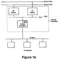
- FIGURE 1b is a schematic representation of an IO bus interface employing the present invention.
- FIGURE 2 diagrammatically illustrates the various sub-bus structures comprising the bus structure employing the teachings of the present invention.
- FIGURE 3 diagrammatically illustrates the structure of queues in the bus watchers and the cache controller employing the teachings of the present invention.
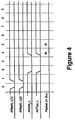
- FIGURE 4 is a timing diagram illustrating the arbitration timing for gaining access to the bus of the present invention.
- FIGURE 5 illustrates the bus interface between a bus watcher and the cache controller for the purpose of computing minimum arbitration latency.
- FIGURE 6 is a timing diagram illustrating the arbitration sequence when the cache controller requests a low priority 2 cycle packet and the cache controller is not the default grantee.
- FIGURE 7 is a timing diagram illustrating the arbitration sequence when the cache controller requests a low priority 2 cycle packet and the cache controller is the default grantee.
- FIGURE 8 is a timing diagram illustrating the arbitration sequence when the bus watcher requests a high priority 9 cycle packet and the bus watcher is not the default grantee.
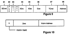
- FIGURE 9 diagrammatically illustrates the various components comprising the header cycle.
- FIGURE 10 diagrammatically illustrates the various components comprising the victim cycle for the GetSingle and GetBlock commands.
- FIGURE 11 diagrammatically illustrates the various components comprising the second cycle for a DemapRqst command.
- FIGURE 12 diagrammatically illustrates the various components comprising the second cycle for an interrupt command.
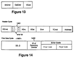
- FIGURE 13 diagrammatically illustrates the various components comprising the tag command within a packet header.
- FIGURE 14 diagrammatically illustrates the various components comprising the header cycle and first data cycle for an error reply packet.
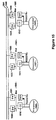
- FIGURE 15 is a schematic representation of the operation of an interrupt command among multiple processors employing the bus of the presently claimed invention.
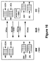
- FIGURE 16 diagrammatically illustrates the operation of the default grantee mechanism.
- the bus of the presently claimed invention is a high speed, synchronous, packet-switched inter-chip bus apparatus and method for transferring data between multiple system buses and a data processing device.
- the data processing device may be either a cache controller coupled to a processor, as shown in Figure 1a , or an IO bus interface coupled to an IO bus, as shown in Figure 1b .
- a cache controller coupled to a processor
- IO bus interface coupled to an IO bus
- the bus 100 connects a cache controller client chip 110 and the external cache RAM 150 of a processor 120 to a plurality of "bus watcher" client chips 130 and 131, each of which is coupled to a separate system bus 140 and 141.
- the bus 100 comprises a plurality of lines including multiplexed data/address path lines, parity lines, and various other command and control lines for flow control and arbitration purposes. Additionally, the bus 100 has a plurality of point-to-point arbitration wires for such devices as the bus watchers 130 and 131 and the cache controller 110.
- the bus 100 allows the cache controller 110 to provide independent processor-side access to the cache 150 and the bus watchers 130 and 131 to handle functions related to bus snooping.
- An arbiter 160 is employed to allow the bus 100 to be multiplexed between the bus watchers 130 and 131 and the cache controller 110. Before a device can send a packet, it must get bus mastership from the arbiter 160. Once the device has control of the bus 100, it transmits the packet onto the bus 100 one cycle at a time without interruption.
- the arbiter 160 is implemented in the cache controller 110, and is specialized to provide low latency for cache misses and to handle flow control for packet-switched system buses 140 and 141.
- the signals on the bus 100 are divided into three functional groups: control signals, arbitration signals and data signals.
- the control signal group contains clock signals 210 and error signals 220; the arbitration group contains request signals 230, grant signals 240 and grant type 250 for each device; and the data signal group contains data signals 270 and parity 280 signal lines.
- signals except the clock signals 210 and data signals 270 are encoded low true.
- Clock signals 210 provide the timing for all bus signals.
- the error signal 220 is used by the cache controller 110 (hereinafter "CC") to indicate an unrecoverable error in CC 110 or the processor 120 to the bus watcher clients 130 and 131 (hereinafter "BW"). In the present embodiment, the error signal 220 is driven active low.
- bus request signals 230 (XReqN: N being the index for the requesting BW) are used by a BW to request the bus 100 and to control the flow of packets being sent by the CC 110.
- a request to use the bus for sending data consists of two contiguous cycles, while flow control requests are one or two cycles.
- a grant signal 240 (XGntN) is used by the arbiter 160 to notify a requestor that it has been granted the bus mastership. This signal is asserted continuously for the number of cycles granted, and is never asserted unless the specific BW (BW-N) has made a request. If the BW Default Grantee mechanism (to be discussed more fully below) is implemented then it is possible for the grant signal to be asserted without a request having been made by the BW. In the present embodiment, the duration of the grant signal 240 is two cycles or nine cycles depending on the length of the packet requested. This signal is always driven.
- a grant-type signal 250 (XGTyp) is used to qualify the grant signal 240, and has exactly the same timing as the grant signal 240.
- XCCAF XCCAF
- the data group contains data 270 and parity 280 signals.
- the data signals 270 (XData) on the bus 100 are bi-directional signals that carry the bulk of the information being transported on the bus 100. During header cycles they carry address and control information; during other cycles they carry data. A device drives these signals only after the receiving a grant signal 240 from the arbiter 160.
- the parity signals 280 (XParity) also comprise a number of bi-directional signals that carry the parity information computed over the data signals 270. The parity for a given value of the data signals appear in the same cycle as the value.
- the bus 100 also has an arbiter 160 that allows the bus 100 to be multiplexed between the BWs 130 and 131 and the CC110.
- a BW or the CC When either a BW or the CC has a packet to send, it makes a request to the arbiter 160 through its dedicated request lines 230 (XReqN), and the arbiter 160 grants the bus 100 using the corresponding grant line 240 (XGntN) and the bussed grant-type line 250 (XGTyp).
- the arbiter 160 implements four priority levels for flow control and deadlock avoidance purposes. Service at a given priority level is round-robin among contenders, while service between levels is based strictly on priorities.
- the arbiter 160 is implemented in the CC 110 because this is simpler and more efficient, as will be appreciated from the following description of the invention.
- the bus 100 imposes the following FIFO queue structure on the BWs 130 and 131 and CC 110.
- Each BW has four system bus queues, two for output, two for input.
- the output queues, DOL 334 and 335 and DOH 336 and 337 are used to send packets at system bus priorities CacheLow and CacheHigh, respectively; the input queues, DIL 330 and 331 and DIH 332 and 333, hold packets that will be sent at bus priorities BWLow and BWHigh, respectively.
- the queue DIH 332 is used to hold only replies to packets originally sent by the CC 110.
- An implementation is also allowed to merge the queues DIL and DIH in the BWs, and XIL 310 and XIH 311 in the CC 110 if deadlock-free operation is still possible with this arrangement.
- the CC 110 also has four packet queues, two for input from the bus 100 and two for output to the bus 100.
- the output queue, XOL 312, is used to send out CC requests, while XOH 313 is used to send out CC replies.
- each CC 110 has two queues, ArbLow 360 and ArbHigh 361, used to hold arbitration requests from the BWs at the priorities BWLow and BWHigh respectively.
- the order-preserving implementation works as follows: when a packet arrives at the input of a BW, a request for control of bus 100 is sent to bus arbiter 160 a fixed number of cycles later. Currently, a request is sent to arbiter 160 two cycles after a packet arrives at the BW.
- bus arbiter 160 receives requests for control of bus 100, it services the requests on a FIFO (First-in, first-out) basis, therefore preserving the system bus arrival order of packets.
- FIFO First-in, first-out
- the BWs 130 and 131 and CC 110 interact with the arbiter 160 through three dedicated wires - XReqN, and XGntN, and the bussed XGTyp 250.
- the arbitration wires for the CC 110 are internal since the arbiter 160 is implemented in the CC 110, while those for the BWs 130 and 131 appear at the pins of the CC 110.
- Each request blocks the queue for 9 cycles but requests do not accumulate. For example 01,00,01 blocks the queue for a total of 11 cycles, not 18. 01,01,01,... Continuous request to block both the XOL and XOH queues. Again, requests do not accumulate. For example 01,01 blocks the queue for 10 cycles, not 18. 10,00,11,10 A 2 cycle BWLow request followed immediately by a 9 cycle BWHigh request. 10,01,11,11 A 2 cycle BWLow request followed immediately by a 9 cycle BWHigh request. In both requests the XOL and XOH queues are blocked.
- the arbiter 160 grants the bus 100 using the requesting client's XGntN line and qualifies this grant using the bussed XGTyp line 250.
- XGntN is asserted for either two consecutive cycles or nine consecutive cycles depending on the length of the packet requested.
- XGTyp specifies whether the current grant is for low priority or high priority; it is asserted for the duration in which the XGntN is asserted.
- the requestor sends a request for a high priority two cycle packet; the arbiter 160 then responds two cycles later with the grant, and a packet appears on the bus 100 two cycles thereafter.
- the arbitration latency is defined as the number of cycles from the assertion of the XReq signal on the bus 100 to the appearance of the packet header on the bus 100, then the resulting arbitration latency in Figure 4 is four cycles. The actual latency depends on whether the bus 100 is busy, what the request priority is, and whether the requestor is a BW 130 and 131 or the CC 110.
- the arbiters 160 supports four priorities: CCLow ⁇ BWLow ⁇ BWHigh ⁇ CCHigh.
- Servicing a request at a given level is round-robin while servicing a request between levels is based strictly on priority.
- Strict priority means that if a low priority request arrives at the arbiter 160 at the same time or after a high priority request, then a low priority request will never be serviced in preference to the high priority request. It will be appreciated that although a round-robin and strict priority system is employed by the present invention that other arbitration and priority schemes which ensure deadlock-free operation may be utilized.
- the CC 110 when the CC 110 needs to send a packet from its XOL 312 queue, for example, a request to read a block from memory or a request to broadcast write to a location, it requests the bus 100 by using the CCLow priority.
- the priority CCHigh is used by the CC to send a packet from the XOH queue 313, for example, a reply to a system bus request to read a block that resides in the cache RAM 150.
- the priority BWLow is used by a BW to send packets from its DIL queue 330 and 331, for example, requests coming in on the system bus 140 and 141 from other processors.
- the priority BWHigh is used by a BW to send packets from its DIH queue 332 and 333, for example, replies from the system bus 140 and 141 to requests sent out earlier by the CC 110.
- the ordering of priorities in the above mentioned manner helps ensure that queues do not overflow and deadlock does not occur.
- various other priority hierarchies may be defined to achieve the same objectives.
- the arbiter 160 also provides mechanisms to prevent the queues receiving packets or arbitration requests over the bus 100 from overflowing.
- the arbiter 160 controls the flow of XIL 310 and XIH 311 by refusing to grant requests to any of the BWs when either of the queues is above its high water mark. As long as the BWs do not get grants, the BWs cannot send packets, and overflow is thus avoided.
- ArbLow 360 is flow-controlled by the arbiter 160 through the signal XCCAF 260 (CC Arbitration Flow).
- XCCAF 260 CC Arbitration Flow
- all of the BWs assert a system bus pause, which stops the flow of those packets on the system bus 140 and 141 that could overflow BW queues. This ensures that no more arbitration requests are sent to ArbLow 360 in the CC 110.
- ArbHigh 361 is prevented from overflowing by limiting the number of outstanding reply packets whose requests were sent by the CC 110 and which would end up in DIN 332 and 333. Again, ArbHigh 361 contains only requests for packets in DIN 332 and 333.
- the flows in DOL 334 and 335 and DOH 336 and 337 are controlled by having the BW signal block through its XReq lines.
- the BW sends a block request identifying XOL 312 or XOH 313 if there is no arbitration request being sent at the moment, otherwise it piggybacks the Block request on top of the arbitration request.
- the default grantee mechanism is employed to avoid the latency cycles during a cache miss due to the minimum arbitration latency of the BW 1630 or the CC 1610 as a bus requestor when the bus 100 is idle.
- the arbiter 1660 gives a bus grant to a client, as the default grantee, even though the client has not made a request. The grant is made in anticipation of a real request, and maintained only as long as there are no requests from other clients.
- the arbiter 1660 is always in one of the three states: No default grantee (NDG), the CC is the default grantee (CCDG), and one of the BW's is the default grantee (BWDG). As long as the CC 1610 has no outstanding packets for a read miss, the arbiter 1660 is in the CCDG state. When a read miss occurs, the CC 1610 will incur zero arbitration latency because it already has the grant. At this time the arbiter 1660 switches to BWDG, asserts the XGnt signal 1640 for the BW 1630 to which a request is made, and also asserts the qualifying XGTyp 1650 to indicate that the default grant applies only to requests from the DIH queue 1632.
- NDG No default grantee
- BWDG default grantee
- the BW 1630 When the miss reply packet comes to the BW 1630, the BW 1630 incurs zero latency if there are no other arbitration requests pending for the bus 100. Thus, for a bus 100 which is mostly idle, the default grantee mechanism will save the minimum arbitration latency cycles from the BW 1630 and from the CC 1610.
- the arbiter 1660 implementation must ensure that the CC 1610 or other BW would not send a packet at the same time as the BW 1630 that is the default grantee. This problem does not arise when the CC 1610 is the default grantee, because the arbiter 1660 is aware of the request due to the internal request line in the CC soon enough.
- arbitration latency is measured from when XReqN 530 is on the bus to when the corresponding header is on the bus; for the CC, whose XReq 515 is internally coupled to the arbitration logic 560 in the CC, XReq 515 is one pipeline away from the bus, and one cycle must be subtracted from the delay between XReq 515 and the header on the bus.
- CCDG the minimum arbitration latency is two cycles; with CCDG it is zero cycles.
- BWDG the minimum latency is four cycles; with BWDG it is zero cycles.
- Figure 6 illustrates the minimum-latency timing diagram for the illustrative circuit in Figure 5 when the CC requests a low priority two-cycle packet and the CC is not the default grantee. Note that the header cycle appears on the bus only after XGnt is asserted (low-true).
- Figure 7 illustrates the minimum-latency timing diagram for the illustrative circuit in Figure 5 when the CC requests a low priority two-cycle packet, and the CC is the default grantee.
- the header cycle appears on the bus two cycles sooner, because the XGnt is already asserted in the CCDG case.
- the CC can use the default grantee either for low priority packets or for high priority packets, but not both. This is because XGTyp is produced too late for the bus sending logic to know whether to send from the XOL queue or from the XOH queue; this decision therefore must be made statically. For optimizing latency for only request packets, this restriction is inconsequential.
- Figure 8 illustrates the minimum-latency timing diagram for the illustrative circuit in Figure 5 when the BW requests a high priority nine cycle packet and the BW is not the default grantee.
- the bus operation can be understood in terms of three levels: cycles, packets, and transactions.
- a cycle is one period of the bus clock; it forms a unit of time and one-way information transfer. All cycles on the bus fall into one of the four categories: Header, Data, Memfault, and Idle.
- a Header cycle is always the first cycle of the packet; Data cycles normally constitute the remaining cycles; Memfault cycles are used to indicate an error in one of the data cycles of a packet; and Idle cycles are those during which no packet is being transmitted on the bus.
- Header and Memfault cycles are encoded using the all-even encoding of the X-Parity wires.
- Memfault is distinguished from Header by the fact that Memfault can only occur in place of one of the Data cycles of a packet.
- Data is distinguished from Idle by the fact that Data cycles occur within a packet whereas Idle cycles do not.
- a packet is a contiguous sequence of cycles that constitute the next higher unit of transfer.
- the first (header) cycle of the packet carries address and control information, while subsequent cycles carry data.
- packets come in two sizes in the present embodiment: two cycles and nine cycles.
- a device sends a packet after arbitrating for the bus and getting the grant. Packet transmission by a device is uninterruptable once the header cycle has been sent.
- a data command field in the packet encodes the packet type, including whether the packet is a request or a reply and the transaction type.
- a transaction consists of a pair of packets (request and reply) that perform some logical function. Packets usually come in pairs, but there are exceptions to this. For a FlushLine transaction (described below), several reply packets may be generated for one request. For a transaction that times out, no reply packet may be generated.
- the bus defines two types of commands that are contained in the header cycle of each packet: a data command, used by the sender to Get or Put data from or to another client. This data may or may not be directly accessible to the receiving client, but this fact is irrelevant to the bus protocol in the present preferred embodiment.
- the receiving client is expected to process the request in an appropriate way: for a Put request, the client will do the action and acknowledge it, and for a Get request, the client will retrieve the data and return it through a subsequent reply packet.
- the header cycles also contain a tag command, which is used to keep the bus-side tags inside the BWs consistent with the processor-side tags inside the CC.
- each device has a unique identification (Device Identification).
- Device Identification Unique Identification
- Multiple devices can reside within a client connected to the bus.
- Each client can use any device identifications allocated to it, subject to the following constraints in the present embodiment:
- header cycles are indicated by the all-even encoding on the parity wires. It will be apparent to those skilled in the art that various other encoding schemes may be employed to achieve the same objective.
- the 64 bits in a header cycle convey the information regarding the data command 91 (DCmd), length of packet 92 (PLen), error 93 (Err), source identification 94 (XSrc), destination device identification 95 (XDst), size 96, tag command 97 (TCmd), and address 98, to be described more fully below.
- DCmd 91 specifies data transfer commands. In the present embodiment, two sizes of data may be transferred: a single, which fits in one 64-bit cycle, and a block, which is eight cycles. Currently, the least significant bit of the data command field also specifies whether the packet is a request or a reply.
- the data commands in the form of DCmd 91 could be divided into three functional groups: the memory group contains commands directed to a system-wide physical address space.
- the IO group contains commands directed to a distinct system-wide IO address space whose contents are never cached.
- the IO space is used primarily to access IO devices, but it also provides a way to read and write the state of system components through the system bus; such access is provided for diagnostic purposes.
- the miscellaneous group contains commands for memory management and interrupt handling.
- the encoding of the data commands is as follows: Table 1 Table of Data Commands Group Command Name Encoding Packet Length Memory NoopRqst / NoopRply 00000 0/1 2/2 cycles - 00001 0/1 - NCGetBlockRqst / Rply 00010 0/1 2/9 cycles FlushLineRqst / Rply 00011 0/1 2/9 cycles GetSingleRqst / Rply 00100 0/1 2/2 cycles PutSingleRqst / Rply 00101 0/1 2/2 cycles GetBlockRqst / Rply 00110 0/1 2/9 cycles PutBlockRqst / Rply 00111 0/1 9/2 or 9/9 cycles IO IOGetSingleRqst /Rply 01000 0/1 2/2 cycles IOPutSingleRqst / Rply 01001 0/1 2/2 cycles IOGetBlockRq
- the length of the packet (PLen) 92 is also indicated in the header cycle.
- the header cycle can specify either a two-cycle packet or a nine-cycle packet.
- the error field (Err) 93 in the header cycle is defined only for reply packets. It indicates that the corresponding request packet encounters an error. The second cycle of an error reply provides additional error information and the remaining cycles, if any, are ignored.
- the length of an error reply packet is the same as the length of the corresponding normal reply packet. Any bit that is not used is set to zero.
- the source field (XSrc) 94 specifies the Device Identification of the device transmitting the packet, while the destination field (XDst) 95 specifies the Device Identification of the device that is the intended recipient of this packet.
- the size field 96 specifies the number of bytes of data that will be transported by the current transaction.
- the 3-bit size field is specified as follows: Size Bits Single 000 1 Byte 001 2 Bytes 010 4 Bytes 011 8 Bytes Block 100 Undefined 101 64 Bytes 110 Undefined 111 Undefined In each case the datum is contiguous and self-aligned within its container.
- the size is a byte, it starts on a byte boundary; if it is 2 bytes, then it starts on a 16-bit boundary, and so on.
- the location of the datum is specified by the low-order bits of the Address field 98 to be described below.
- the address field 98 in the header cycle identifies a byte in a single or block addressed by the current packet. Blocks and singles are required to be contiguous and self-aligned within the address space. When fewer than the allocated bits are used in the address field 98, the unused bits must be in the high order part of the field and be set to zero. In the present preferred embodiment, the ordering of bytes within a block is "big-endian"; that is, low order address bits equal to zero specifies the most significant byte in the single or block.
- the addressed quantity is a single, the low order three bits of the address field 98 specified byte 0 (the leftmost byte) within the quantity. Thus, for a double word, the low order three bits of the address field are zero; for a word the low order two bits are zero, and for a half-word the low order bit is zero. When the addressed quantity is a block, the low order 3 bits are zero.
- the Noop command indicates that no data is being transferred. It is useful because it allows the tags of an entry to be manipulated through the tag command without having to transfer data.
- a Noop request packet is two cycles long, the first being the header and the second cycle being unused.
- a Noop reply packet is used to reply to a Noop request.
- the data command field in a Noop reply packet differs from that of a Noop request packet only in the reply/request bit; and the destination field 95 is identical to the request packet's source field 94.
- NCGetBlock is used by a bus device to read a block from the physical address space when it does not intend to cache the block.
- An NCGetBlockRqst packet requests that the block specified by the address field 98 in the header be returned through an NCGetBlockRply.
- the packet is two cycles long. The first cycle contains the header, while the second cycle is unused.
- the NCGetBlockRply packet is a response to an earlier NCGetBlockRqst.
- the packet is nine cycles long.
- the header cycle reflects most of the information in the request header, while the eight cycles of data supply the requested block in cyclic order, where the cycle containing the addressed byte is delivered first followed by cycles with increasing address MOD 8. With the exception of the request/reply difference, all other fields are the same as in the header cycle, and the destination field 95 is identical to the request packet's source field 94.
- the low order three bits of address 98 are ignored and are set to zero.
- the FlushLine command is used to transfer a line from the CC to a BW for the purpose of writing it back to main memory.
- a FlushLineRqst packet is always initiated by the CC. It requests the CC to return those blocks of the line that need to be written back, i.e. those that have the owner set.
- the packet is two cycles long. The first cycle contains the header, while the second cycle is unused.
- a FlushLineRply packet is a response to an earlier FlushLineRqst. The packet is nine cycles long.
- the header cycle reflects most of the information in the request header, while the eight cycles of data supply the requested block in normal order, where the cycle containing byte 0 of the block is delivered first followed by cycles with increasing address.
- the lower six bits of the address field are ignored, and are set to zero. With the exception of the request/reply difference in the header cycle, all other fields are the same as in the request packet, and the destination field 95 is identical to the request packet's source field 94. The number of the block within the line to be flushed is also provided in the address field 98.
- a FlushLineRqst packet may generate more than one FlushLineRply packet because a cache line contains multiple blocks.
- the destination field 95 in each reply packet is set to the Device Identification of the BW such that all FlushLineRply packets are sent to the same BW. There is no provision for cross-BW flushes in the present preferred embodiment.
- the GetSingle command is used to fetch a single (64 bits) of data from the 36-bit physical address space.
- a GetSingleRqst packet requests that the single specified by the size 96 and address 98 fields in the header cycle be returned through a GetSingleRply.
- a GetSingleRqst packet is two cycles long. The first cycle is the header, while the second cycle contains the address of the block being victimized, if any.
- the format of the victim cycle is shown in Figure 10 . A valid bit indicates whether the victim address is valid. This format applies to all packets that contain a victim cycle.
- a GetSingleReply packet contains a header, which reflects most of the information in the request header, and data, which supplies the requested single. With the exception of the request/reply difference in the header cycle, all other fields are the same as in the request packet, and the destination field 95 is identical to the request packet's source field 94.
- the PutSingle command is used to store a single (64 bits) of data into the 36-bit physical address space.
- a PutSingleRqst packet requests that a given value, which may be a byte, a half-word, a word, or a double-word, be written into the single specified by the size 96 and address 98 fields of the header.
- a PutSingleRply packet is used to acknowledge an earlier PutSingleRqst. It contains a header reflecting most of the information in the request header and the data to be written just as in the request packet. With the exception of the request/reply difference in the header cycle, all other fields are the same as in the request packet, and the destination field 95 is identical to the request packet's source field 94.
- the SwapSingle command is used to perform an atomic load-store on a single (64 bits) of data in the 36 bit physical address space.
- a SwapSingleRqst packet requests that a given value, which may be a byte, a half-word, a word, or a double-word, be atomically written into the single specified by the size 96 and address 98 fields of the header and the old value be returned.
- a SwapSingleRqst is two cycles long, with the first being the header and the second containing the value to be written.
- a SwapSingleRply packet is used to acknowledge an earlier SwapSingleRqst.
- It contains a header, which reflects most of the information in the request header, and the data, which is to be written, just as in the request packet. With the exception of the request/reply difference in the header cycle, all other fields are identical, and the destination field 95 is identical to the request packet's source field 94.
- the GetBlock command is used to read a block from the physical address space with the intent of cacheing it.
- a GetBlockRqst packet requests that the block specified by the address field 98 in the header cycle be returned through a GetBlockRply.
- a GetBlockRqst packet contains the header and the address of the block being victimized, if any.
- Figure 10 also shows the format of the victim cycle.
- a GetBlockReply packet is a response to an earlier GetBlockRqst.
- the packet contains the header cycle reflecting most of the information in the request header and the data supplying the requested block in cyclic order, where the cycle containing the addressed byte is delivered first followed by cycles with increasing address MOD 8.
- the destination field 95 is identical to the request packet's source field 94.
- the low order 3 bits of the address field 98 are ignored, and are set to zero since the transaction involves a complete block.
- the PutBlock command is used to write a block into the physical address space.
- a PutBlockRqst packet requests that a given value be written into the block specified by the address field 98 of the header.
- a Putblock packet is nine cycles long. The first cycle is the header, while the remaining cycles, which are in normal order, contain the value to be written. Currently, Bits[5..0] of the address field are ignored, and are zero.
- a PutBlockRply packet is a response to an earlier PutBlockRqst.
- a two-cycle PutBlockRply simply acknowledges that the PutBlockRqst requested earlier has been done.
- the first cycle is the header while the second cycle is unused (its value is "don't care").
- a nine-cycle PutBlockRply not only acknowledges the PutBlockRqst, but also supplies the data to be written, which are in normal order.
- all other fields are identical, and the destination field 95 is identical to the request packet's source field 94.
- the low order 6 bits of the address field 98 are ignored, and are set to zero.
- the IOGetSingle command is used to read a single from the IO address space.
- An IOGetSingleRqst packet requests that the single specified by the size 96 and address 98 fields in the header cycle be returned through an IOGetSingleRply.
- an IOGetSingleRqst packet is two cycles long. The first cycle contains the header, while the second cycle is unused.
- An IOGetSingleRply packet is a response to an earlier IOGetSingleRqst. The packet is two cycles long. The first cycle contains the header, while the second cycle supplies the requested data. With the exception of the request/reply difference in the header cycle, all other fields are identical, and the destination field 95 is identical to the request packet's source field 94.
- the IOPutSingle command is used to write a single into the IO address space.
- An IOPutSingleRqst packet requests that a given value, which may be a byte, a half-word, a word, or a double-word, be written be written into the single specified by the size 96 and address 98 fields of the header.
- the packet is two cycles long. The first cycle contains the header, while the second cycle contains the value to be written.
- An IOPutSingleRply packet acknowledges that an earlier IOPutSingleRqst is complete. The packet is 2 cycles long.. The first cycle contains the header, while the second cycle is unused. With the exception of the request/reply difference in the header cycle, all other fields are identical, and the destination field 95 is identical to the request packet's source field 94.
- the IOSwapSingle command is used to atomically store a single into the IO address space and return the old value.
- An IOSwapSingleRqst packet requests that a given value, which may be a byte, a half-word, a word, or a double-word, be written into the single specified by the size 96 and address 98 fields of the header and the old value be returned.
- the packet is two cycles long. The first cycle contains the header, while the second cycle contains the value to be written.
- An IOSwapSingleRply packet acknowledges that an earlier IOswapSingleRqst is complete. The packet is two cycles long.
- the first cycle contains the header, while the second cycle contains the data returned by the destination device for the atomic load-store.
- the second cycle contains the data returned by the destination device for the atomic load-store.
- all other fields are identical, and the destination field 95 is identical to the request packet's source field 94.
- the IOGetBlock command is used to read a block of data from the IO address space.
- An IOGetBlock Rqst packet requests that the block specified by the address field in the header be returned through an IOGetBlockRply.
- the packet is two cycles. The first cycle contains the header, while the second cycle is unused.
- An IOGetblockRply packet is a response to an earlier IOGetBlockRqst.
- the packet is nine cycles long.
- the header cycle reflects most of the information in the request header, while the data cycles supply the requested block in normal order. Currently, Bits[5..0] of the address field are ignored, and are set to zero. With the exception of the request/reply difference in the header cycle, all other fields are identical, and the destination field 95 is identical to the request packet's source field 94.
- the IOPutBlock command is used to write a block of data into the IO address space.
- An IOPutBlock packet requests that a given value be written into the block specified by the address field of the header.
- the packet is nine cycles long.
- the first cycle contains the header, while the remaining cycles contain the data, which are in normal order. Currently, Bits[5..0] of the address field are ignored, and are set to zero.
- An IOPutBlockRply packet acknowledges that the write requested by an earlier IOPutBlockRqst is complete.
- the packet is two cycles long.
- the first cycle contains the header, while the second cycle is unused. With the exception of the request/reply difference in the header cycle, all other fields are identical, and the destination field 95 is identical to the request packet's source field 94.
- the Demap command is used to remove the virtual to physical mapping for one or more virtual pages.
- a processor wants to demap a page, its CC issues a DemapRqest on the bus with the destination field 95 set to zero.
- BW0 picks up the packet and sends it onto the system bus.
- each BW except the initiating BW0
- receives the request it forwards a DemapRqst packet through its bus to the CC.
- the CC uses a DemapRply to notify its BW0 that the Demap is complete locally.
- the initiating BW0 uses the DemapReply to notify its CC that the Demap is complete in all other caches.
- DemapRqst consists of two cycles: the address field 98 in the header cycle must be all zeros, while the entity to be demapped is specified in the second cycle. While the format of the second cycle is not relevant to the bus, it is shown in Figure 11 to better describe the invention.
- the fields VPN, Type, and RSV in Figure 11 please refer to SPARC Reference MMU, Section 3.4, available from Sun Microsystems, Inc., Mountain View, California.
- the DemapRply packet acknowledges an earlier DemapRqst packet; it is two cycles long.
- the first cycle contains the header with the address field 98 set to all zeros.
- the second cycle is unused, and its contents are "don't care".
- the Interrupt command is used to generate processor interrupts. Because the interrupt lines are carried on the bus, it is different from prior art buses, where the interrupt lines are separate from the bus.
- Each interrupt has an initiating bus 1500, and one or more target buses 1501 and 1502.
- the initiating bus 1500 contains the device that generated the interrupt, while the target buses are the ones whose processors 1521 and 1522 are to be interrupted.
- the interrupt command is used both at the initiating end and the target ends.
- a processor 1520 initiates an interrupt
- its CC 1510 sends an InterruptRqst packet to one of its BWs 1530, which forwards this packet on to the system bus 1540.
- the BW 1530 receives its own packet from the system bus 1540, the BW 1530 responds with an InterruptRpty packet to notify its CC 1510. If the BW 1530 itself is not one of the targets of the interrupt, this reply packet serves only as an acknowledgement, Otherwise, it serves both as an acknowledgement and as a request to interrupt the local processor 1520.
- the interrupt request arrives over the system bus 1540 and is forwarded by the BW 1534 as an InterruptRqst packet on the target bus 1502.
- the CC 1512 Once the CC 1512 has interrupted the processor 1522, it acknowledges the InterruptRqst packet with an IntertuptRply.
- both InterruptRqst and InterruptRply packets consist of two cycles.
- the first cycle contains the header with the address field set to zero
- the second cycle contains the interrupt data formatted as shown in Figure 12 .
- the TargetID and IntID are interpreted by the BW's when an interrupt packet is received over the system bus. While the format is not relevant to the bus, it is recited below to better describe the invention.
- B is the broadcast bit, which specifies whether all processors are to be interrupted or just the processor designated by the TargetID. The TargetID is ignored when the broadcast bit is asserted.
- the IntSID specifies the source for the interrupt.
- the SetBits field is interpreted on the bus. It specifies the bits that must be set in the CC's interrupt status register when it receives an interrupt request or reply.
- the Tag Command 97 (TCmd) within a packet header as shown in Figure 9 specifies how the tag for the entry specified by the address portion 98 of the header should be manipulated.
- the BW's and CC use TCmd 97 to keep their copies of tags in synchrony.
- a tag contains four flags: Shared, Owner, Valid, and Pending, and some address comparison, or AComp bits.
- cache tags are kept entirely within the IO caches (IOC). Thus, this embodiment does not use the TCmd field for the purpose of keeping tags consistent.
- the four flags have the following meanings: the Shared bit indicates whether the entry is present in more than one cache on the system bus.
- the Owner bit indicates whether this copy should respond to reads over the system bus.
- the Valid field indicates whether the entry is valid or not; multiple bits are used because some consistency algorithms need multiple valid states. The current embodiment uses a single valid bit.
- the Pending state is useful only for packet-switched buses: it indicates whether the entry has a packet outstanding on the system bus.
- the AComp field contains those bits of the address that are not used as an index into the Tag array.
- TCmd consists of three parts: a ShCmd that indicates how the Shared bit should be manipulated, a OwCmd that indicates how the Owner bit should be manipulated, and a VCmd that indicate how the Valid and Tag bits should be manipulated.
- the ShCmd and OwCmd fields can be encoded as follows: Encoding Meaning 00 Write the value 0 01 Write the value 1 10 Expect the value 0 11 Expect the value 1
- the two Expect codes are provided to the destination device for information purposes. Currently, the implementation does not require checking that the local copy of the tag bits have the expected value, but this may be done for better error detection.
- the VCmd field is encoded as follows: Encoding Meaning 00 Decrement 01 Clear Valid 10 Set Valid and Write Tag 11 Noop Decrement is used by the BW to signal the CC that the valid bits for a line in the cache should be decremented as a result of an external write from another processor. When the valid bits for that line are reset, the line disappears from the cache for that local processor, This is an implementation called “competitive cacheing," where a processor avoids the expense of going to the lines of other processors' caches for a write by trying to eliminate those lines by decrementing their valid bits. On the other hand, the local processor retains its line in the cache by incrementing the valid bits so that a cache miss can be avoided and the processor does not have to go to the main memory during a cache miss.
- Set Valid and Write Tag is used by the BW to signal the CC that the information is new and the processor-side tags should be updated to maintain consistency between the tags.
- Clear Valid is used to remove a block from the cache without using the competitive cacheing implementation,
- the bus provides a single mechanism for detecting bus errors.
- four parity bits check the 64 bits of data as follows: XParity[3] check XData[63..48], XParity[2] check XData[47..32], XParity[1] checks XData[31..16], and XParity[0] checks XData[15..0].
- XParity wires are also used to encode whether the cycle is a Header, Data, Memfault, or Idle.
- the first is to set the Err bit 1401 in a reply packet
- the second is to convert a Data cycle 1400 for the packet into a Memfault cycle.
- the first mechanism is used when the error is detected early enough so it can be reported in the header cycle.
- the length of an error reply packet must be the same as the length of the corresponding normal reply packet.
- the second mechanism is used when the error is detected only after the packet header has been sent.
- Figure 14 shows the format of the header cycle and the first data cycle 1400 when an error is reported in the header cycle.
- Memfault cycle The format of a Memfault cycle is identical to that of the first data cycle 1400 shown in Figure 14 .
- ErrorCode itself is divided into a MajorCode that divides the error into one of 16 broad categories, and a MinorCode that provides more detailed information about the error.
Abstract
Description
- The present invention relates to apparatus and methods for transferring data between a source and a plurality of data processing devices. More particularly, the present invention relates to an improved bus apparatus and method for transferring data between multiple system buses and a data processing device, such as a cache controller or an IO bus interface.
- In the computing industry it is quite common to transfer data and commands between a plurality of data processing devices, such as computers, printers, memories, and the like, on a system or data bus. A data processing system typically includes a processor which executes instructions that are stored in addresses in a memory. The data that is processed is transferred into and out of the system by way of input/output (IO) devices, onto a bus which interconnects the data processing system with other digital hardware. Common constraints on the speed of data transfer between data processing devices coupled to a bus or protocol or "handshake" restrictions which require a pre-determined sequence of events to occur within specified time periods prior to actual date of exchange between the devices. It is therefore desirable to have a low latency and high bandwidth bus which operates quickly to minimize the computing time required for a particular task. The protocol utilized by the bus should be designed to be as efficient as possible and minimize the time required for data transfer.
- Another limitation on a computer bus is the size of the bus itself. Essentially, a bus is a collection of wires connecting the various components of a computer system. In addition to address lines and data lines, the bus will typically contain clock signal lines, power lines, and other control signal lines. As a general rule, the speed of the bus can be increased simply by adding more lines to the bus. This allows the bus to carry more data at a given time. However, as the number of lines increases, so does the cost of the bus. It is therefore desirable to have a bus which operates as quickly as possible while also maintaining a bus of economical size. One such bus is disclosed in three U.S. patent applications, filed Nov. 30, 1990, by Sindhu et al, assigned to the co-Assignee of the present application, Xerox Corporation, entitled:
CONSISTENT PACKET-SWITCHED MEMORY BUS FOR SHARED MEMORY MULTI-PROCESSORS, CONSISTENCY PROTOCOLS FOR SHARED MEMORY MULTI-PROCESSORS, and ARBITRATION OF PACKET-SWITCHED BUSES INCLUDING BUSES FOR SHARED MEMORY MULTI-PROCESSORS. - As will be described, the present invention provides a high speed, synchronous, packet-switched bus apparatus and method for transferring data between multiple system buses and a cache controller of a processor. In comparison with the prior art circuit-switched buses allowing only one outstanding operation, the present packet-switched bus allows multiple outstanding operations. The present invention also has an arbitration implementation that allows lower latency than other prior art packet-switched buses. As will be appreciated from the following description, the present invention permits higher performance processors and IO devices to be utilized in a system without requiring the use of extremely high pincount packages or extremely dense VLSI technologies. In the cache controller embodiment, the present invention permits a larger dual-port cache to be built by spreading the tags over multiple chips. A larger cache results in higher hit rate and therefore better processor performance. This larger cache also had available to it a higher system bus bandwidth since it is connected to multiple system buses. Higher bandwidth also translates directly to improved processor performance. In the IO bus interface embodiment, the present invention permits multiple high bandwidth IO devices to be connected to multiple system buses in such a way that each IO device has uniform access to all system buses. This provides each IO device with a large available IO bandwidth and therefore allows it to provide a high throughput of IO operations.
- A high speed, synchronous, packet-switched inter-chip bus apparatus and method is disclosed. In the present invention, the bus connects a cache controller client chip within the external cache of a processor to a plurality of bus watcher client chips, each of which is coupled to a separate system bus. The bus comprises a plurality of lines including multiplexed data/address path lines, parity lines, and various other command and control lines for flow control and arbitration purposes. Additionally, the bus has a plurality of point-to-point arbitration wires for each device. A variety of logical entities, referred to as "devices", can send and receive packets on the bus, each device having a unique device identification. A "chip" coupled to the bus can have multiple devices coupled to it and can use any device identification allocated to it.
- The bus operates at three levels: cycles, packets, and transactions. A bus cycle is one period of the bus clock; it forms the unit of time and one-way information transfer. A packet is a contiguous sequence of cycles that constitutes the next higher unit of transfer. The first cycle of a packet, called a header, carries address and control information, while subsequent cycles carry data. In the present invention, packets come in two sizes: two cycles and nine cycles. A transaction is the third level: it consists of a pair of packets (request, reply) that together performs some logical function.
- The bus allows the cache controller to provide independent processor-side access to the cache and the bus watchers to handle functions related to bus snooping. An arbiter is employed to allow the bus to be multiplexed between the bus watchers and the cache controller. Before a device can send a packet, it must get bus mastership from the arbiter. Once the device has control of the bus, it transmits the packet onto the bus one cycle at a time without interruption. The arbiter is implemented in the cache controller, and is specialized to provide low latency for cache misses and to handle flow control for packet-switched system buses. Packet transmission on the bus is point-to-point in that only the recipient identified in a packet typically takes action on the packet. These flow control mechanisms ensure that the queues receiving packets or arbitration requests over the bus never overflow. A default grantee mechanism is employed to minimize the arbitration latency due to a request for the control of the bus when the bus is idle. A mechanism is further employed to preserve the arrival order of packets on system buses as the packets arrive on the bus of the present invention.
- Packet headers contain a data command, control signals, a tag command, source and destination bus identifications, and an address. The data command indicates the type of data transfer between the bus watchers and the cache controller, while the tag command is used to keep the bus-side and the processor-side copies of the cache tags consistent with one another. The data command (with the exception of the rqst/rply bit) and address in reply packets are the same as those for the corresponding request packet. These commands, along with the control signals, provide sufficient flexibility to accommodate a variety of system buses.
- FIGURE 1a is a schematic representation of a processor system employing the preferred embodiment of the present invention.
- FIGURE 1b is a schematic representation of an IO bus interface employing the present invention.
- FIGURE 2 diagrammatically illustrates the various sub-bus structures comprising the bus structure employing the teachings of the present invention.
- FIGURE 3 diagrammatically illustrates the structure of queues in the bus watchers and the cache controller employing the teachings of the present invention.
- FIGURE 4 is a timing diagram illustrating the arbitration timing for gaining access to the bus of the present invention.
- FIGURE 5 illustrates the bus interface between a bus watcher and the cache controller for the purpose of computing minimum arbitration latency.
- FIGURE 6 is a timing diagram illustrating the arbitration sequence when the cache controller requests a
low priority 2 cycle packet and the cache controller is not the default grantee. - FIGURE 7 is a timing diagram illustrating the arbitration sequence when the cache controller requests a
low priority 2 cycle packet and the cache controller is the default grantee. - FIGURE 8 is a timing diagram illustrating the arbitration sequence when the bus watcher requests a
high priority 9 cycle packet and the bus watcher is not the default grantee. - FIGURE 9 diagrammatically illustrates the various components comprising the header cycle.
- FIGURE 10 diagrammatically illustrates the various components comprising the victim cycle for the GetSingle and GetBlock commands.
- FIGURE 11 diagrammatically illustrates the various components comprising the second cycle for a DemapRqst command.
- FIGURE 12 diagrammatically illustrates the various components comprising the second cycle for an interrupt command.
- FIGURE 13 diagrammatically illustrates the various components comprising the tag command within a packet header.
- FIGURE 14 diagrammatically illustrates the various components comprising the header cycle and first data cycle for an error reply packet.
- FIGURE 15 is a schematic representation of the operation of an interrupt command among multiple processors employing the bus of the presently claimed invention.
- FIGURE 16 diagrammatically illustrates the operation of the default grantee mechanism.
- An improved high speed, synchronous, packet-switched inter-chip bus apparatus and method is described having particular application for use in high bandwidth and low latency connections between the various parts of a cache. In the following description for purposes of explanation specific memory sizes, bit arrangements, numbers, data transfer rates, etc. are set forth in order to provide a thorough understanding of the present invention. It will be apparent to one skilled in the art, however, that the present invention may be practiced without these specific details. In other instances, well known circuits and components are shown in block diagram form in order not to obscure the present invention unnecessarily.
- The bus of the presently claimed invention is a high speed, synchronous, packet-switched inter-chip bus apparatus and method for transferring data between multiple system buses and a data processing device. The data processing device may be either a cache controller coupled to a processor, as shown in Figure 1a, or an IO bus interface coupled to an IO bus, as shown in Figure 1b. To simplify the description, terminology associated with Figure 1a will be used throughout the present application. It should be born in mind, however, that the description for the cache controller embodiment also applies to the IO bus interface, except where indicated otherwise.
- Referring to Figure 1a, the
bus 100 connects a cachecontroller client chip 110 and theexternal cache RAM 150 of a processor 120 to a plurality of "bus watcher" client chips 130 and 131, each of which is coupled to aseparate system bus bus 100 comprises a plurality of lines including multiplexed data/address path lines, parity lines, and various other command and control lines for flow control and arbitration purposes. Additionally, thebus 100 has a plurality of point-to-point arbitration wires for such devices as thebus watchers cache controller 110. - The
bus 100 allows thecache controller 110 to provide independent processor-side access to thecache 150 and thebus watchers arbiter 160 is employed to allow thebus 100 to be multiplexed between thebus watchers cache controller 110. Before a device can send a packet, it must get bus mastership from thearbiter 160. Once the device has control of thebus 100, it transmits the packet onto thebus 100 one cycle at a time without interruption. Thearbiter 160 is implemented in thecache controller 110, and is specialized to provide low latency for cache misses and to handle flow control for packet-switchedsystem buses - Referring to Figure 2, the signals on the
bus 100 are divided into three functional groups: control signals, arbitration signals and data signals. The control signal group contains clock signals 210 and error signals 220; the arbitration group contains request signals 230, grant signals 240 andgrant type 250 for each device; and the data signal group contains data signals 270 andparity 280 signal lines. In the present preferred embodiment, signals except the clock signals 210 and data signals 270 are encoded low true. Clock signals 210 provide the timing for all bus signals. Theerror signal 220 is used by the cache controller 110 (hereinafter "CC") to indicate an unrecoverable error inCC 110 or the processor 120 to thebus watcher clients 130 and 131 (hereinafter "BW"). In the present embodiment, theerror signal 220 is driven active low. However, there is no corresponding error signal from the BWs to the CC because unrecoverable errors inBWs system bus bus 100 supports up to four BW's and four corresponding system buses solely due to the limitation by thecache controller 110. In the arbitration group, bus request signals 230 (XReqN: N being the index for the requesting BW) are used by a BW to request thebus 100 and to control the flow of packets being sent by theCC 110. In the present embodiment, a request to use the bus for sending data consists of two contiguous cycles, while flow control requests are one or two cycles. The signals are encoded as follows:First Cycle Second Cycle Meaning 00 - No Request 01 - Block CC Request Queue (XOL) for 9 cycles 01 01 Block XOL and CC Reply Queue (XOH) for 9 cycles 10 L0 Request bus at Priority BWLow for 2 cycles if L=0; 9 cycles if L=1. 10 L1 Request bus at Priority BWLow for 2 cycles if L=0; 9 cycles if L=1; and block XOL and XOH for 9 cycles. 11 L0 Request bus at Priority BWHigh tor 2 cycles if L=0; 9 cycles if L=1.11 L1 Request bus at Priority BWHigh for 2 cycles if L=0; 9 cycles if L=1; and block XOL and XOH for 9 cycles. Currently, these signals are driven active low. - A grant signal 240 (XGntN) is used by the
arbiter 160 to notify a requestor that it has been granted the bus mastership. This signal is asserted continuously for the number of cycles granted, and is never asserted unless the specific BW (BW-N) has made a request. If the BW Default Grantee mechanism (to be discussed more fully below) is implemented then it is possible for the grant signal to be asserted without a request having been made by the BW. In the present embodiment, the duration of thegrant signal 240 is two cycles or nine cycles depending on the length of the packet requested. This signal is always driven. A grant-type signal 250 (XGTyp) is used to qualify thegrant signal 240, and has exactly the same timing as thegrant signal 240. Currently, this signal is driven active low. Finally a signal 260 (XCCAF) is used by theCC 110 to notify theBWs - The data group contains
data 270 andparity 280 signals. The data signals 270 (XData) on thebus 100 are bi-directional signals that carry the bulk of the information being transported on thebus 100. During header cycles they carry address and control information; during other cycles they carry data. A device drives these signals only after the receiving agrant signal 240 from thearbiter 160. The parity signals 280 (XParity) also comprise a number of bi-directional signals that carry the parity information computed over the data signals 270. The parity for a given value of the data signals appear in the same cycle as the value. - As will be described, the
bus 100 also has anarbiter 160 that allows thebus 100 to be multiplexed between theBWs arbiter 160 through its dedicated request lines 230 (XReqN), and thearbiter 160 grants thebus 100 using the corresponding grant line 240 (XGntN) and the bussed grant-type line 250 (XGTyp). In the present embodiment, thearbiter 160 implements four priority levels for flow control and deadlock avoidance purposes. Service at a given priority level is round-robin among contenders, while service between levels is based strictly on priorities. Thearbiter 160 is implemented in theCC 110 because this is simpler and more efficient, as will be appreciated from the following description of the invention. - Referring to Figure 3, the
bus 100 imposes the following FIFO queue structure on theBWs CC 110. Each BW has four system bus queues, two for output, two for input. The output queues,DOL DOH DIL 330 and 331 and DIH 332 and 333, hold packets that will be sent at bus priorities BWLow and BWHigh, respectively. The queue DIH 332 is used to hold only replies to packets originally sent by theCC 110. An implementation is also allowed to merge the queues DIL and DIH in the BWs, andXIL 310 andXIH 311 in theCC 110 if deadlock-free operation is still possible with this arrangement. - Referring to Figure 3, the
CC 110 also has four packet queues, two for input from thebus 100 and two for output to thebus 100. The input queues,XIL 310 andXIH 311, hold packets fromDIL 330 and 331 and DIH 332 and 333, respectively. The output queue,XOL 312, is used to send out CC requests, whileXOH 313 is used to send out CC replies. Additionally, eachCC 110 has two queues,ArbLow 360 andArbHigh 361, used to hold arbitration requests from the BWs at the priorities BWLow and BWHigh respectively. If the delay from the reception of packet on thesystem bus bus 100 is fixed then these queues ensure that the packets from multiple system buses in each class (DIL or DIH) are serviced by thebus arbiter 160 in their system bus arrival order. In the present embodiment, ordering is not maintained between packets in one class and those in the other. - Referring again to Figure 3, when packets are transferred from
system buses CC 110 throughbus 100 of the present invention, the following scheme is used to ensure that packets arriving onbus 100 are in the same order as they arrive onrespective system buses system bus 140 atcycle 1 and packet B arrives onsystem bus 141 atcycle 4. An order-preserving implementation of the present invention will preserve the arrival order of packets A and B onsystem buses bus 100, i.e. packet A arriving onbus 100 before packet B. Conversely, if packet B arrives onsystem bus 141 before packet B arrives onsystem bus 140, then packet B is transferred ontobus 100 before packet A. Currently, the arrival order is preserved for packets entering thequeues DIL 330 and 331. - The order-preserving implementation works as follows: when a packet arrives at the input of a BW, a request for control of
bus 100 is sent to bus arbiter 160 a fixed number of cycles later. Currently, a request is sent toarbiter 160 two cycles after a packet arrives at the BW. Whenbus arbiter 160 receives requests for control ofbus 100, it services the requests on a FIFO (First-in, first-out) basis, therefore preserving the system bus arrival order of packets. - In a case where both packets A and B arrive on their
respective system buses bus 100. In the current embodiment, packets from BW0 are transferred tobus 100 first in the case of simultaneous arrival on the system buses. However, it will be apparent to those skilled in the art that other fallback schemes are also available for the case of simultaneous arrival. - The
BWs CC 110 interact with thearbiter 160 through three dedicated wires - XReqN, and XGntN, and the bussedXGTyp 250. In the present preferred embodiment, the arbitration wires for theCC 110 are internal since thearbiter 160 is implemented in theCC 110, while those for theBWs CC 110. A BW requests thebus 100 by using its XReqN lines as follows:First Cycle Second Cycle Meaning 00 - No Request 01 - Block XOL for 9 cycles 01 01 Block XOL and XOH for 9 cycles 10 L0 Request Bus at Priority BWLow for 2 cycles if L = 0 and 9 cycles if L = 1. 10 L1 Request Bus at Priority BWLow for 2 cycles if L = 0 and 9 cycles if L = 1 and block XOL and XOH for 9 cycles. 11 L0 Request Bus at Priority BWHigh for 2 cycles if L = 0 and 9 cycles if L = 1. 11 L1 Request Bus at Priority BWHigh for 2 cycles if L = 0 and 9 cycles if L = 1 and block XOL and XOH for 9 cycles. CC 110, the Block portion of the codes are ignored by thearbiter 160. The following example illustrates the encoding in the above table.00,00,00,... No requests of any kind. 01,00,01,00,... Continuous request to block the XOL queue. Each request blocks the queue for 9 cycles but requests do not accumulate. For example 01,00,01 blocks the queue for a total of 11 cycles, not 18. 01,01,01,... Continuous request to block both the XOL and XOH queues. Again, requests do not accumulate. For example 01,01 blocks the queue for 10 cycles, not 18. 10,00,11,10 A 2 cycle BWLow request followed immediately by a 9 cycle BWHigh request.10,01,11,11 A 2 cycle BWLow request followed immediately by a 9 cycle BWHigh request. In both requests the XOL and XOH queues are blocked. - The
arbiter 160 grants thebus 100 using the requesting client's XGntN line and qualifies this grant using the bussedXGTyp line 250. In the present embodiment, XGntN is asserted for either two consecutive cycles or nine consecutive cycles depending on the length of the packet requested. XGTyp specifies whether the current grant is for low priority or high priority; it is asserted for the duration in which the XGntN is asserted. - Reference is now made to the generic arbitration timing diagram in Figure 4. The requestor sends a request for a high priority two cycle packet; the
arbiter 160 then responds two cycles later with the grant, and a packet appears on thebus 100 two cycles thereafter. If the arbitration latency is defined as the number of cycles from the assertion of the XReq signal on thebus 100 to the appearance of the packet header on thebus 100, then the resulting arbitration latency in Figure 4 is four cycles. The actual latency depends on whether thebus 100 is busy, what the request priority is, and whether the requestor is aBW CC 110. - In the present embodiment, the
arbiters 160 supports four priorities: CCLow < BWLow < BWHigh < CCHigh. Servicing a request at a given level is round-robin while servicing a request between levels is based strictly on priority. Strict priority means that if a low priority request arrives at thearbiter 160 at the same time or after a high priority request, then a low priority request will never be serviced in preference to the high priority request. It will be appreciated that although a round-robin and strict priority system is employed by the present invention that other arbitration and priority schemes which ensure deadlock-free operation may be utilized. - Referring again to Figure 3, when the
CC 110 needs to send a packet from itsXOL 312 queue, for example, a request to read a block from memory or a request to broadcast write to a location, it requests thebus 100 by using the CCLow priority. The priority CCHigh is used by the CC to send a packet from theXOH queue 313, for example, a reply to a system bus request to read a block that resides in thecache RAM 150. The priority BWLow is used by a BW to send packets from itsDIL queue 330 and 331, for example, requests coming in on thesystem bus DIH queue 332 and 333, for example, replies from thesystem bus CC 110. The ordering of priorities in the above mentioned manner helps ensure that queues do not overflow and deadlock does not occur. However, once again it will be apparent to one skilled in the art that various other priority hierarchies may be defined to achieve the same objectives. - The
arbiter 160 also provides mechanisms to prevent the queues receiving packets or arbitration requests over thebus 100 from overflowing. In the present embodiment, there are six such queues:XIL 310,XIH 311,ArbLow 360 andArbHigh 361 in theCC 110, andDOL DOH BW arbiter 160 controls the flow ofXIL 310 andXIH 311 by refusing to grant requests to any of the BWs when either of the queues is above its high water mark. As long as the BWs do not get grants, the BWs cannot send packets, and overflow is thus avoided.ArbLow 360 is flow-controlled by thearbiter 160 through the signal XCCAF 260 (CC Arbitration Flow). When theXCCAF 260 signal is asserted, all of the BWs assert a system bus pause, which stops the flow of those packets on thesystem bus ArbLow 360 in theCC 110.ArbHigh 361 is prevented from overflowing by limiting the number of outstanding reply packets whose requests were sent by theCC 110 and which would end up inDIN 332 and 333. Again,ArbHigh 361 contains only requests for packets inDIN 332 and 333. The flows inDOL DOH request identifying XOL 312 orXOH 313 if there is no arbitration request being sent at the moment, otherwise it piggybacks the Block request on top of the arbitration request. Each time thearbiter 160 receives a block request (piggybacked or not) it blocks the appropriate queues for the requested number of cycles. Block requests are not accumulated, and so, for example, two contiguous block requests for nine cycles each will block the specific queue for eleven cycles, not eighteen cycles. - Reference is now made to Figure 16 to illustrate the operation of the default grantee mechanism. Currently, the default grantee mechanism is employed to avoid the latency cycles during a cache miss due to the minimum arbitration latency of the BW 1630 or the
CC 1610 as a bus requestor when thebus 100 is idle. However, it will be apparent to those skilled in the art that the default grantee mechanism can be implemented for other latency-critical operations as well. To implement the default grantee, the arbiter 1660 gives a bus grant to a client, as the default grantee, even though the client has not made a request. The grant is made in anticipation of a real request, and maintained only as long as there are no requests from other clients. - The arbiter 1660 is always in one of the three states: No default grantee (NDG), the CC is the default grantee (CCDG), and one of the BW's is the default grantee (BWDG). As long as the
CC 1610 has no outstanding packets for a read miss, the arbiter 1660 is in the CCDG state. When a read miss occurs, theCC 1610 will incur zero arbitration latency because it already has the grant. At this time the arbiter 1660 switches to BWDG, asserts theXGnt signal 1640 for the BW 1630 to which a request is made, and also asserts thequalifying XGTyp 1650 to indicate that the default grant applies only to requests from theDIH queue 1632. When the miss reply packet comes to the BW 1630, the BW 1630 incurs zero latency if there are no other arbitration requests pending for thebus 100. Thus, for abus 100 which is mostly idle, the default grantee mechanism will save the minimum arbitration latency cycles from the BW 1630 and from theCC 1610. - Referring to Figure 16, when a BW 1630 is the default grantee it must be prepared for the event that its
XGntN line 1640 is de-asserted by theCC 1610 while the BW 1630 is about to send, or is actually sending a packet from itsDIH queue 1632. This happens when theCC 1610 or another BW makes a request while the BW 1630 is the default grantee. There is no way for the arbiter to know that the BW 1630 is about to send because a packet header and the request signal appear simultaneously on the pins of that BW 1630; therefore, there is no appropriate time for the arbiter 1660 to de-assert the BW'sXGntN line 1640. If the BW 1630 has not started to send whenXGntN 1640 is de-asserted, it must wait until it getsXGntN 1640 again before it can send the packet. If it has started sending, then it must continue the transmission to complete even thoughXGntN 1640 has been de-asserted. The arbiter 1660 implementation must ensure that theCC 1610 or other BW would not send a packet at the same time as the BW 1630 that is the default grantee. This problem does not arise when theCC 1610 is the default grantee, because the arbiter 1660 is aware of the request due to the internal request line in the CC soon enough. - One consequence of having a default grantee mechanism is that the arbitration latency for a device that is not the default grantee is greater than it would have been without the mechanism. In the BW of the present embodiment, the latency increases from four cycles to five. However, this increase has little impact on the performance because it affects only references to shared data from other processors, which are infrequent and not latency-critical. If BWDG is implemented, the latency for the CC increases from one to three, but only for the references made while a miss is already outstanding. Since these references are either shared writes, write misses, or prefetches, performance is virtually unaffected.
- Reference is now made to Figure 5, for the purpose of illustrating pipeline delays between the BWs and CC, and for computing minimum arbitration latency. With respect to the speed of transmission and logic, the following assumptions are made:
- · The path between inputs and outputs of the
arbitration logic 560 is combinatorial, and its delay is less than one clock cycle. Thearbitration logic 560 also contains a state machine and the ArbHigh and ArbLow FIFOs without adding a pipeline delay to the best-case path between inputs and outputs. - ·
XReqN 530,XGntN 540,XGTyp 550 andXdata 570 can be transferred from the flip-flop 512 in the sending client to the flip-flop 511 in the receiving client in less than one clock cycle. - · The delayed version of
XGntN 541 can go through the ANDgate 513 and be transferred to the outbound flip-flop 512 in less than one clock cycle. - Given the schematics in Figure 5, it is possible to compute the minimum arbitration latency for the cases with and without a default grantee. As stated before, arbitration latency is measured from when
XReqN 530 is on the bus to when the corresponding header is on the bus; for the CC, whoseXReq 515 is internally coupled to thearbitration logic 560 in the CC,XReq 515 is one pipeline away from the bus, and one cycle must be subtracted from the delay betweenXReq 515 and the header on the bus. Without CCDG, the minimum arbitration latency is two cycles; with CCDG it is zero cycles. Without BWDG, the minimum latency is four cycles; with BWDG it is zero cycles. Thus, if both the BWDG and CCDG were implemented it would save six cycles, and if only the CCDG is implemented it would save two cycles. - Figure 6 illustrates the minimum-latency timing diagram for the illustrative circuit in Figure 5 when the CC requests a low priority two-cycle packet and the CC is not the default grantee. Note that the header cycle appears on the bus only after XGnt is asserted (low-true).
- Figure 7 illustrates the minimum-latency timing diagram for the illustrative circuit in Figure 5 when the CC requests a low priority two-cycle packet, and the CC is the default grantee. When compared to no CCDG as in Figure 6, the header cycle appears on the bus two cycles sooner, because the XGnt is already asserted in the CCDG case. Currently, the CC can use the default grantee either for low priority packets or for high priority packets, but not both. This is because XGTyp is produced too late for the bus sending logic to know whether to send from the XOL queue or from the XOH queue; this decision therefore must be made statically. For optimizing latency for only request packets, this restriction is inconsequential.
- Figure 8 illustrates the minimum-latency timing diagram for the illustrative circuit in Figure 5 when the BW requests a high priority nine cycle packet and the BW is not the default grantee.
- The bus operation can be understood in terms of three levels: cycles, packets, and transactions. A cycle is one period of the bus clock; it forms a unit of time and one-way information transfer. All cycles on the bus fall into one of the four categories: Header, Data, Memfault, and Idle. A Header cycle is always the first cycle of the packet; Data cycles normally constitute the remaining cycles; Memfault cycles are used to indicate an error in one of the data cycles of a packet; and Idle cycles are those during which no packet is being transmitted on the bus. Currently, Header and Memfault cycles are encoded using the all-even encoding of the X-Parity wires. Data and Idle cycles are encoded using the all-odd encoding of the X-Parity wires. Memfault is distinguished from Header by the fact that Memfault can only occur in place of one of the Data cycles of a packet. Data is distinguished from Idle by the fact that Data cycles occur within a packet whereas Idle cycles do not.
- A packet is a contiguous sequence of cycles that constitute the next higher unit of transfer. The first (header) cycle of the packet carries address and control information, while subsequent cycles carry data. Currently, packets come in two sizes in the present embodiment: two cycles and nine cycles. A device sends a packet after arbitrating for the bus and getting the grant. Packet transmission by a device is uninterruptable once the header cycle has been sent. A data command field in the packet encodes the packet type, including whether the packet is a request or a reply and the transaction type.
- A transaction consists of a pair of packets (request and reply) that perform some logical function. Packets usually come in pairs, but there are exceptions to this. For a FlushLine transaction (described below), several reply packets may be generated for one request. For a transaction that times out, no reply packet may be generated.
- The bus defines two types of commands that are contained in the header cycle of each packet: a data command, used by the sender to Get or Put data from or to another client. This data may or may not be directly accessible to the receiving client, but this fact is irrelevant to the bus protocol in the present preferred embodiment. The receiving client is expected to process the request in an appropriate way: for a Put request, the client will do the action and acknowledge it, and for a Get request, the client will retrieve the data and return it through a subsequent reply packet. The header cycles also contain a tag command, which is used to keep the bus-side tags inside the BWs consistent with the processor-side tags inside the CC.
- With respect to sending and receiving packets on the bus using the bus commands, each device has a unique identification (Device Identification). Multiple devices can reside within a client connected to the bus. Each client can use any device identifications allocated to it, subject to the following constraints in the present embodiment:
- · One set of device identifications is reserved for the CC client; and such numbers also identify the device within the CC. Currently, device identification numbers of the form "0dddd" are reserved for the CC; and "dddd" is the number for one of up to 16 devices within the CC.
- · Another set of numbers is reserved for the BW clients; such numbers also identify the device within the BW. Currently, device identification numbers of the form "1dddd" are reserved for the BW clients; and dddd is the number for one of up to 16 devices within the BW.
- Reference is now made to Figure 9, where the format of a header cycle is shown. In the present embodiment, header cycles are indicated by the all-even encoding on the parity wires. It will be apparent to those skilled in the art that various other encoding schemes may be employed to achieve the same objective. Currently, the 64 bits in a header cycle convey the information regarding the data command 91 (DCmd), length of packet 92 (PLen), error 93 (Err), source identification 94 (XSrc), destination device identification 95 (XDst),
size 96, tag command 97 (TCmd), andaddress 98, to be described more fully below. -
DCmd 91 specifies data transfer commands. In the present embodiment, two sizes of data may be transferred: a single, which fits in one 64-bit cycle, and a block, which is eight cycles. Currently, the least significant bit of the data command field also specifies whether the packet is a request or a reply. - The data commands in the form of
DCmd 91 could be divided into three functional groups: the memory group contains commands directed to a system-wide physical address space. The IO group contains commands directed to a distinct system-wide IO address space whose contents are never cached. The IO space is used primarily to access IO devices, but it also provides a way to read and write the state of system components through the system bus; such access is provided for diagnostic purposes. Finally the miscellaneous group contains commands for memory management and interrupt handling. In the present embodiment the encoding of the data commands is as follows:Table 1 Table of Data Commands Group Command Name Encoding Packet Length Memory NoopRqst / NoopRply 00000 0/1 2/2 cycles - 00001 0/1 - NCGetBlockRqst / Rply 00010 0/1 2/9 cycles FlushLineRqst / Rply 00011 0/1 2/9 cycles GetSingleRqst / Rply 00100 0/1 2/2 cycles PutSingleRqst / Rply 00101 0/1 2/2 cycles GetBlockRqst / Rply 00110 0/1 2/9 cycles PutBlockRqst / Rply 00111 0/1 9/2 or 9/9 cycles IO IOGetSingleRqst /Rply 01000 0/1 2/2 cycles IOPutSingleRqst / Rply 01001 0/1 2/2 cycles IOGetBlockRqst / Rply 01010 0/1 2/9 cycles IOPutBlockRqst / Rply 01011 0/1 9/2 cycles Misc. - 01100 0/1 - - 01101 0/1 - DemapRqst / Rply 01110 0/1 2/2 cycles InterruptRqst / Rply 01111 0/1 2/2 cycles Memory - 10000 0/1 - - 10001 0/1 - - 10010 0/1 - - 10011 0/1 - - 10100 0/1 - SwapSingleRqst / Rply 10101 0/1 2/2 cycles - 10110 0/1 - - 10111 0/1 - IO - 11000 0/1 - IO SwapSingleRqst / Rply 11001 0/1 2/2 cycles - 11010 0/1 - - 11011 0/1 - Misc. - 11100 0/1 - - 11101 0/1 - - 11110 0/1 - - 11111 0/1 - - The length of the packet (PLen) 92 is also indicated in the header cycle. For the present preferred embodiment, the header cycle can specify either a two-cycle packet or a nine-cycle packet. The error field (Err) 93 in the header cycle is defined only for reply packets. It indicates that the corresponding request packet encounters an error. The second cycle of an error reply provides additional error information and the remaining cycles, if any, are ignored. The length of an error reply packet is the same as the length of the corresponding normal reply packet. Any bit that is not used is set to zero. The source field (XSrc) 94 specifies the Device Identification of the device transmitting the packet, while the destination field (XDst) 95 specifies the Device Identification of the device that is the intended recipient of this packet. If the packet is a request, only the device indicated by the
XDst 95 can generate a reply. WhenXDst 95 specifies a BW, there will be bits in theaddress field 98 in the header cycle specifying the BW number. Thesize field 96 specifies the number of bytes of data that will be transported by the current transaction. In the present preferred embodiment, the 3-bit size field is specified as follows:Size Bits Single 000 1 Byte 001 2 Bytes 010 4 Bytes 011 8 Bytes Block 100 Undefined 101 64 Bytes 110 Undefined 111 Undefined
In each case the datum is contiguous and self-aligned within its container. Thus if the size is a byte, it starts on a byte boundary; if it is 2 bytes, then it starts on a 16-bit boundary, and so on. The location of the datum is specified by the low-order bits of theAddress field 98 to be described below. - The
address field 98 in the header cycle identifies a byte in a single or block addressed by the current packet. Blocks and singles are required to be contiguous and self-aligned within the address space. When fewer than the allocated bits are used in theaddress field 98, the unused bits must be in the high order part of the field and be set to zero. In the present preferred embodiment, the ordering of bytes within a block is "big-endian"; that is, low order address bits equal to zero specifies the most significant byte in the single or block. When the addressed quantity is a single, the low order three bits of theaddress field 98 specified byte 0 (the leftmost byte) within the quantity. Thus, for a double word, the low order three bits of the address field are zero; for a word the low order two bits are zero, and for a half-word the low order bit is zero. When the addressed quantity is a block, thelow order 3 bits are zero. - Reference is now made to the various data commands as shown in Table 1 below. The Noop command indicates that no data is being transferred. It is useful because it allows the tags of an entry to be manipulated through the tag command without having to transfer data. In the present embodiment a Noop request packet is two cycles long, the first being the header and the second cycle being unused. A Noop reply packet is used to reply to a Noop request. As shown in Table 1, the data command field in a Noop reply packet differs from that of a Noop request packet only in the reply/request bit; and the
destination field 95 is identical to the request packet'ssource field 94. - NCGetBlock is used by a bus device to read a block from the physical address space when it does not intend to cache the block. An NCGetBlockRqst packet requests that the block specified by the
address field 98 in the header be returned through an NCGetBlockRply. In the present preferred embodiment, the packet is two cycles long. The first cycle contains the header, while the second cycle is unused. The NCGetBlockRply packet is a response to an earlier NCGetBlockRqst. In the present embodiment, the packet is nine cycles long. The header cycle reflects most of the information in the request header, while the eight cycles of data supply the requested block in cyclic order, where the cycle containing the addressed byte is delivered first followed by cycles with increasingaddress MOD 8. With the exception of the request/reply difference, all other fields are the same as in the header cycle, and thedestination field 95 is identical to the request packet'ssource field 94. The low order three bits ofaddress 98 are ignored and are set to zero. - The FlushLine command is used to transfer a line from the CC to a BW for the purpose of writing it back to main memory. A FlushLineRqst packet is always initiated by the CC. It requests the CC to return those blocks of the line that need to be written back, i.e. those that have the owner set. In the present preferred embodiment, the packet is two cycles long. The first cycle contains the header, while the second cycle is unused. A FlushLineRply packet is a response to an earlier FlushLineRqst. The packet is nine cycles long. The header cycle reflects most of the information in the request header, while the eight cycles of data supply the requested block in normal order, where the
cycle containing byte 0 of the block is delivered first followed by cycles with increasing address. In the present preferred embodiment, the lower six bits of the address field are ignored, and are set to zero. With the exception of the request/reply difference in the header cycle, all other fields are the same as in the request packet, and thedestination field 95 is identical to the request packet'ssource field 94. The number of the block within the line to be flushed is also provided in theaddress field 98. - A FlushLineRqst packet may generate more than one FlushLineRply packet because a cache line contains multiple blocks. The
destination field 95 in each reply packet is set to the Device Identification of the BW such that all FlushLineRply packets are sent to the same BW. There is no provision for cross-BW flushes in the present preferred embodiment. - The GetSingle command is used to fetch a single (64 bits) of data from the 36-bit physical address space. A GetSingleRqst packet requests that the single specified by the
size 96 and address 98 fields in the header cycle be returned through a GetSingleRply. A GetSingleRqst packet is two cycles long. The first cycle is the header, while the second cycle contains the address of the block being victimized, if any. The format of the victim cycle is shown in Figure 10. A valid bit indicates whether the victim address is valid. This format applies to all packets that contain a victim cycle. - A GetSingleReply packet contains a header, which reflects most of the information in the request header, and data, which supplies the requested single. With the exception of the request/reply difference in the header cycle, all other fields are the same as in the request packet, and the
destination field 95 is identical to the request packet'ssource field 94. - The PutSingle command is used to store a single (64 bits) of data into the 36-bit physical address space. A PutSingleRqst packet requests that a given value, which may be a byte, a half-word, a word, or a double-word, be written into the single specified by the
size 96 and address 98 fields of the header. A PutSingleRply packet is used to acknowledge an earlier PutSingleRqst. It contains a header reflecting most of the information in the request header and the data to be written just as in the request packet. With the exception of the request/reply difference in the header cycle, all other fields are the same as in the request packet, and thedestination field 95 is identical to the request packet'ssource field 94. - The SwapSingle command is used to perform an atomic load-store on a single (64 bits) of data in the 36 bit physical address space. A SwapSingleRqst packet requests that a given value, which may be a byte, a half-word, a word, or a double-word, be atomically written into the single specified by the
size 96 and address 98 fields of the header and the old value be returned. In the present preferred embodiment, a SwapSingleRqst is two cycles long, with the first being the header and the second containing the value to be written. A SwapSingleRply packet is used to acknowledge an earlier SwapSingleRqst. It contains a header, which reflects most of the information in the request header, and the data, which is to be written, just as in the request packet. With the exception of the request/reply difference in the header cycle, all other fields are identical, and thedestination field 95 is identical to the request packet'ssource field 94. - The GetBlock command is used to read a block from the physical address space with the intent of cacheing it. A GetBlockRqst packet requests that the block specified by the
address field 98 in the header cycle be returned through a GetBlockRply. A GetBlockRqst packet contains the header and the address of the block being victimized, if any. Figure 10 also shows the format of the victim cycle. - A GetBlockReply packet is a response to an earlier GetBlockRqst. The packet contains the header cycle reflecting most of the information in the request header and the data supplying the requested block in cyclic order, where the cycle containing the addressed byte is delivered first followed by cycles with increasing
address MOD 8. With the exception of the request/reply difference in the header cycle, all other fields are the same as in the request cycle, and thedestination field 95 is identical to the request packet'ssource field 94. In the present embodiment, thelow order 3 bits of theaddress field 98 are ignored, and are set to zero since the transaction involves a complete block. - The PutBlock command is used to write a block into the physical address space. A PutBlockRqst packet requests that a given value be written into the block specified by the
address field 98 of the header. In the present embodiment, a Putblock packet is nine cycles long. The first cycle is the header, while the remaining cycles, which are in normal order, contain the value to be written. Currently, Bits[5..0] of the address field are ignored, and are zero. - A PutBlockRply packet is a response to an earlier PutBlockRqst. In the present embodiment, there are two sizes of PutBlockRply: two cycles and nine cycles. A two-cycle PutBlockRply simply acknowledges that the PutBlockRqst requested earlier has been done. The first cycle is the header while the second cycle is unused (its value is "don't care"). A nine-cycle PutBlockRply not only acknowledges the PutBlockRqst, but also supplies the data to be written, which are in normal order. In both types of packet, with the exception of the request/reply difference in the header cycle, all other fields are identical, and the
destination field 95 is identical to the request packet'ssource field 94. Currently, thelow order 6 bits of theaddress field 98 are ignored, and are set to zero. - The IOGetSingle command is used to read a single from the IO address space. An IOGetSingleRqst packet requests that the single specified by the
size 96 and address 98 fields in the header cycle be returned through an IOGetSingleRply. In the present embodiment, an IOGetSingleRqst packet is two cycles long. The first cycle contains the header, while the second cycle is unused. An IOGetSingleRply packet is a response to an earlier IOGetSingleRqst. The packet is two cycles long. The first cycle contains the header, while the second cycle supplies the requested data. With the exception of the request/reply difference in the header cycle, all other fields are identical, and thedestination field 95 is identical to the request packet'ssource field 94. - The IOPutSingle command is used to write a single into the IO address space. An IOPutSingleRqst packet requests that a given value, which may be a byte, a half-word, a word, or a double-word, be written be written into the single specified by the
size 96 and address 98 fields of the header. In the present embodiment, the packet is two cycles long. The first cycle contains the header, while the second cycle contains the value to be written. An IOPutSingleRply packet acknowledges that an earlier IOPutSingleRqst is complete. The packet is 2 cycles long.. The first cycle contains the header, while the second cycle is unused. With the exception of the request/reply difference in the header cycle, all other fields are identical, and thedestination field 95 is identical to the request packet'ssource field 94. - The IOSwapSingle command is used to atomically store a single into the IO address space and return the old value. An IOSwapSingleRqst packet requests that a given value, which may be a byte, a half-word, a word, or a double-word, be written into the single specified by the
size 96 and address 98 fields of the header and the old value be returned. In the present embodiment, the packet is two cycles long. The first cycle contains the header, while the second cycle contains the value to be written. An IOSwapSingleRply packet acknowledges that an earlier IOswapSingleRqst is complete. The packet is two cycles long. The first cycle contains the header, while the second cycle contains the data returned by the destination device for the atomic load-store. With the exception of the request/reply difference in the header cycle, all other fields are identical, and thedestination field 95 is identical to the request packet'ssource field 94. - The IOGetBlock command is used to read a block of data from the IO address space. An IOGetBlock Rqst packet requests that the block specified by the address field in the header be returned through an IOGetBlockRply. In the present embodiment, the packet is two cycles. The first cycle contains the header, while the second cycle is unused. An IOGetblockRply packet is a response to an earlier IOGetBlockRqst. The packet is nine cycles long. The header cycle reflects most of the information in the request header, while the data cycles supply the requested block in normal order. Currently, Bits[5..0] of the address field are ignored, and are set to zero. With the exception of the request/reply difference in the header cycle, all other fields are identical, and the
destination field 95 is identical to the request packet'ssource field 94. - The IOPutBlock command is used to write a block of data into the IO address space. An IOPutBlock packet requests that a given value be written into the block specified by the address field of the header. In the present embodiment, the packet is nine cycles long. The first cycle contains the header, while the remaining cycles contain the data, which are in normal order. Currently, Bits[5..0] of the address field are ignored, and are set to zero. An IOPutBlockRply packet acknowledges that the write requested by an earlier IOPutBlockRqst is complete. The packet is two cycles long. The first cycle contains the header, while the second cycle is unused. With the exception of the request/reply difference in the header cycle, all other fields are identical, and the
destination field 95 is identical to the request packet'ssource field 94. - The Demap command is used to remove the virtual to physical mapping for one or more virtual pages. When a processor wants to demap a page, its CC issues a DemapRqest on the bus with the
destination field 95 set to zero. BW0 picks up the packet and sends it onto the system bus. As each BW (except the initiating BW0) receives the request, it forwards a DemapRqst packet through its bus to the CC. The CC uses a DemapRply to notify its BW0 that the Demap is complete locally. The initiating BW0 uses the DemapReply to notify its CC that the Demap is complete in all other caches. - In the present embodiment, DemapRqst consists of two cycles: the
address field 98 in the header cycle must be all zeros, while the entity to be demapped is specified in the second cycle. While the format of the second cycle is not relevant to the bus, it is shown in Figure 11 to better describe the invention. For a definition of the fields VPN, Type, and RSV in Figure 11, please refer to SPARC Reference MMU, Section 3.4, available from Sun Microsystems, Inc., Mountain View, California. - The DemapRply packet acknowledges an earlier DemapRqst packet; it is two cycles long. The first cycle contains the header with the
address field 98 set to all zeros. The second cycle is unused, and its contents are "don't care". - Referring now to Figure 15, the Interrupt command is used to generate processor interrupts. Because the interrupt lines are carried on the bus, it is different from prior art buses, where the interrupt lines are separate from the bus. Each interrupt has an initiating bus 1500, and one or more target buses 1501 and 1502. The initiating bus 1500 contains the device that generated the interrupt, while the target buses are the ones whose
processors - When a processor 1520 initiates an interrupt, its
CC 1510 sends an InterruptRqst packet to one of itsBWs 1530, which forwards this packet on to thesystem bus 1540. When theBW 1530 receives its own packet from thesystem bus 1540, theBW 1530 responds with an InterruptRpty packet to notify itsCC 1510. If theBW 1530 itself is not one of the targets of the interrupt, this reply packet serves only as an acknowledgement, Otherwise, it serves both as an acknowledgement and as a request to interrupt the local processor 1520. - When a
processor 1522 is the target of an interrupt initiated by some other bus, the interrupt request arrives over thesystem bus 1540 and is forwarded by theBW 1534 as an InterruptRqst packet on the target bus 1502. Once theCC 1512 has interrupted theprocessor 1522, it acknowledges the InterruptRqst packet with an IntertuptRply. - In the present embodiment, both InterruptRqst and InterruptRply packets consist of two cycles. In each case the first cycle contains the header with the address field set to zero, and the second cycle contains the interrupt data formatted as shown in Figure 12.
- Referring to Figure 12, the TargetID and IntID are interpreted by the BW's when an interrupt packet is received over the system bus. While the format is not relevant to the bus, it is recited below to better describe the invention. In the present embodiment, B is the broadcast bit, which specifies whether all processors are to be interrupted or just the processor designated by the TargetID. The TargetID is ignored when the broadcast bit is asserted. Finally, the IntSID specifies the source for the interrupt. The SetBits field is interpreted on the bus. It specifies the bits that must be set in the CC's interrupt status register when it receives an interrupt request or reply.
- As will be described below, the Tag Command 97 (TCmd) within a packet header as shown in Figure 9 specifies how the tag for the entry specified by the
address portion 98 of the header should be manipulated. In general, the BW's andCC use TCmd 97 to keep their copies of tags in synchrony. A tag contains four flags: Shared, Owner, Valid, and Pending, and some address comparison, or AComp bits. In the IO bus interface embodiment, cache tags are kept entirely within the IO caches (IOC). Thus, this embodiment does not use the TCmd field for the purpose of keeping tags consistent. - The four flags have the following meanings: the Shared bit indicates whether the entry is present in more than one cache on the system bus. The Owner bit indicates whether this copy should respond to reads over the system bus. The Valid field indicates whether the entry is valid or not; multiple bits are used because some consistency algorithms need multiple valid states. The current embodiment uses a single valid bit. The Pending state is useful only for packet-switched buses: it indicates whether the entry has a packet outstanding on the system bus. The AComp field contains those bits of the address that are not used as an index into the Tag array.
- Referring to Figure 13, TCmd consists of three parts: a ShCmd that indicates how the Shared bit should be manipulated, a OwCmd that indicates how the Owner bit should be manipulated, and a VCmd that indicate how the Valid and Tag bits should be manipulated.
- The ShCmd and OwCmd fields can be encoded as follows:
Encoding Meaning 00 Write the value 001 Write the value 110 Expect the value 011 Expect the value 1
The two Expect codes are provided to the destination device for information purposes. Currently, the implementation does not require checking that the local copy of the tag bits have the expected value, but this may be done for better error detection. - The VCmd field is encoded as follows:
Encoding Meaning 00 Decrement 01 Clear Valid 10 Set Valid and Write Tag 11 Noop
Decrement is used by the BW to signal the CC that the valid bits for a line in the cache should be decremented as a result of an external write from another processor. When the valid bits for that line are reset, the line disappears from the cache for that local processor, This is an implementation called "competitive cacheing," where a processor avoids the expense of going to the lines of other processors' caches for a write by trying to eliminate those lines by decrementing their valid bits. On the other hand, the local processor retains its line in the cache by incrementing the valid bits so that a cache miss can be avoided and the processor does not have to go to the main memory during a cache miss. - Set Valid and Write Tag is used by the BW to signal the CC that the information is new and the processor-side tags should be updated to maintain consistency between the tags. Clear Valid is used to remove a block from the cache without using the competitive cacheing implementation,
- The bus provides a single mechanism for detecting bus errors. In the present embodiment, four parity bits check the 64 bits of data as follows: XParity[3] check XData[63..48], XParity[2] check XData[47..32], XParity[1] checks XData[31..16], and XParity[0] checks XData[15..0]. However, it will be apparent to those skilled in the art that other parity-checking schemes may also be employed. The XParity wires are also used to encode whether the cycle is a Header, Data, Memfault, or Idle.
- There are two mechanisms for reporting errors over the bus, and both apply to reply packets. Referring Figure 14, the first is to set the
Err bit 1401 in a reply packet, and the second is to convert a Data cycle 1400 for the packet into a Memfault cycle. The first mechanism is used when the error is detected early enough so it can be reported in the header cycle. The length of an error reply packet must be the same as the length of the corresponding normal reply packet. The second mechanism is used when the error is detected only after the packet header has been sent. - Figure 14 shows the format of the header cycle and the first data cycle 1400 when an error is reported in the header cycle.
- The format of a Memfault cycle is identical to that of the first data cycle 1400 shown in Figure 14. ErrorCode itself is divided into a MajorCode that divides the error into one of 16 broad categories, and a MinorCode that provides more detailed information about the error.
- Although the present invention has been described with reference to Figures 1-16, it will be appreciated that the teachings of the present invention may be applied to a variety of inter-chip and/or interprocess bus structures.
Claims (21)
- A packet-switched bus for transferring data between a plurality of system buses and a cache controller of a cache for storing data, said cache controller being coupled to a processor, comprising:
data lines coupled to said system buses and said cache controller for transmitting data and command information between said system buses and said cache controller;
control lines coupled to said system buses and said cache controller for transmitting a plurality of clock signals, said clock signals being coupled to said system buses and said cache controller;
priority arbitration means coupled to said system buses and said cache controller for coupling said system buses and cache controller to said packet-switched bus based on a predetermined priority hierarchy;
sending and receiving means for sending and receiving data and command information to and from said system buses and said packet-switched bus, said sending and receiving means being coupled to said system buses and said packet-switched bus, said sending and receiving means including:
storage means for storing and monitoring a disjointed set of cache tags for said cache for each of said system buses; and
overflow control means coupled to said system buses and said cache controller for preventing said priority arbitration means and said sending and receiving means from overflow;
whereby data is transferred between said cache controller and said system buses. - The bus as defined by claim 1, wherein said priority arbitration means includes means for automatically coupling said packet-switched bus to said cache controller when said packet-switched bus is idle but before data and commands are transferred from said processor to said cache controller, such that as soon as control of said bus is requested, data and commands will be transferred from said controller to said system buses through said packet-switched bus; said priority arbitration means then coupling said packet-switched bus to said sending and receiving means after the data and commands have been transferred to said system bus but before a response from said system bus arrives at said sending and receiving means such that said response can be transferred from said sending and receiving means to said controller through said packet-switched bus as soon as control of said packet-switched bus is requested by said sending and receiving means when said response arrives from said system bus.
- The bus as defined by claim 1, further including generating and acknowledging means coupled to said data lines for generating and acknowledging processor interrupts.
- The bus as defined by claim 3, wherein said generating and acknowledging means for generating and acknowledging interrupts comprises:
means for identifying a target to be interrupted;
means for identifying a source to issue said interrupt. - The bus as defined by claim 1, wherein said priority arbitration means is disposed in said cache controller.
- The bus as defined by claim 1, wherein said plurality of clock signals permits events on said packet switched bus to be synchronous with respect to a predetermined clocking rate.
- In a computer system including a plurality of system buses coupled to a plurality of cache controllers, each of said cache controller coupled to a cache RAM and to a processor, a packet-switched bus for transferring data between said system buses and said cache controllers, comprising:
data lines coupled to said system buses and said cache controllers for transmitting data and command information between said system buses and said cache controller;
control lines coupled to said system buses and said cache controller for transmitting a plurality of clock signals, said clock signals being coupled to said system buses and said cache controller;
priority arbitration means coupled to said system buses and said cache controller for coupling said system buses and cache controller to said packet-switched bus based on a predetermined priority hierarchy;
sending and receiving means for sending and receiving data and command information to and from said system buses and said packet-switched bus, said sending and receiving means being coupled to said system buses and said packet-switched bus, said sending and receiving means including:
storage means for storing and monitoring a disjointed set of cache tags for said cache for each of said system buses; and
overflow control means coupled to said system buses and said cache controller for preventing said priority arbitration means and said sending and receiving means from overflow;
whereby data is transferred between said cache controller and said system buses. - The bus as defined by claim 7, wherein said priority arbitration means coupled to each of said packet switched buses includes means for automatically coupling said packet-switched bus to said cache controller when said packet-switched bus is idle but before data and commands are transferred from said processor to said cache controller, such that as soon as control of said bus is requested, data and commands will be transferred from said controller to said system buses through said packet-switched bus; said priority arbitration means then coupling said packet-switched bus to said sending and receiving means after the data and commands have been transferred to said system bus but before a response from said system bus arrives at said sending and receiving means such that said response can be transferred from said sending and receiving means to said controller through said packet-switched bus as soon as control of said packet-switched bus is requested by said sending and receiving means when said response arrives from said system bus.
- The bus as defined by claim 7, further including generating and acknowledging means coupled to said data lines for generating and acknowledging processor interrupts.
- The bus as defined by claim 9, wherein said generating and acknowledging means for generating and acknowledging interrupts comprises:
means for identifying a target to be interrupted;
means for identifying a source to issue said interrupt. - The bus as defined by claim 7, wherein said priority arbitration means is disposed in each of said cache controller.
- The bus as defined by claim 7, wherein said plurality of clock signals permits events on said packet switched bus to be synchronous with respect to a predetermined clocking rate.
- A method for transferring data on a packet-switched bus coupled between a plurality of system buses and a cache controller of a processor, comprising the steps of:
providing data and command information from either said system buses or said cache controller to be transferred over said packet switched bus;
arbitrating for control of said packet switched bus using priority arbitration means based on a predetermined priority hierarchy, including the steps of:
transmitting a request signal for control of said packet switched bus on data lines coupled to said system buses and said cache controller; and
receiving a grant signal for control of said packet switched bus on said data lines coupled to said system buses and said cache controller;
transferring said data and command information on said data lines coupled to said system buses and said cache controller to either of said system buses by sending and receiving means coupled to said system buses and said cache controller;
controlling data flow over said packet switched bus through overflow control means to prevent said arbitration means and said sending and receiving means from exceeding the data transfer capability of said packet switched bus with data and command information, including:
deasserting said grant signal for control of said packet switched bus by said sending and receiving means when said sending and receiving means contains requests for control of said packet switched bus beyond a first predetermined level;
halting flow of data from said system buses into said sending and receiving means and flow of request signals from said sending and receiving means to said cache controller when said arbitration means contains request signals for control of said packet switched bus beyond a second predetermined level;
halting flow of reply signals from said cache controller to said sending and receiving means when said arbitration means contains request signals for control of said packet switched bus beyond a third predetermined level; and
halting flow of data from said cache controller to said sending and receiving means when said sending and receiving means contains data to be sent on said system buses beyond a fourth predetermined level;
whereby data is transferred between said system buses and said cache controller. - A method for avoiding arbitration latency for transferring data on a bus coupled to a plurality of data processing devices ("agents"), comprising:
granting control of said bus to a first agent when said bus is idle, said first agent being selected based on a predetermined criteria;
generating a request for transferring data on said bus by said first agent when an event for gaining control of said bus arises;
transferring data through said bus from said first agent to a second agent; and
granting control of said bus to said second agent for a predetermined cycles,
whereby data is transferred from said second agent to said first agent over said bus without arbitration latency. - A method for minimizing arbitration latency for transferring data on a first bus coupled to a plurality of system buses and a cache controller, said latency occurring when control of said first bus is requested for a cache miss while said first bus is idle, comprising the steps of:
granting control of said first bus to said cache controller when said first bus is idle and said processor experiences a cache miss;
generating a request for control of said first bus upon a cache miss by said processor;
transferring a request for data and command to one of said system buses through receiving and sending means coupled to each of said system buses, said receiving and sending means being coupled to said first bus;
granting control of said first bus to said receiving and sending means of said system bus;
whereby, upon arrival of a reply for said request at said receiving and sending means, said reply is transferred to said cache controller without arbitration delay. - In a computer system including a plurality of system buses coupled to a plurality of cache controllers, each of said cache controllers coupled to a cache RAM and to a processor, a method for minimizing arbitration latency for transferring data on a first bus coupled to said plurality of system buses and said cache controller, said latency occurring when control of said first bus is requested for a cache miss while said first bus is idle, comprising the steps of:
granting control of said first bus to said cache controller when said first bus is idle and said processor experiences a cache miss;
generating a request for control of said first bus upon a cache miss by said processor;
transferring a request for data and command to one of said system buses through receiving and sending means coupled to each of said system buses, said receiving and sending means being coupled to said first bus;
granting control of said first bus to said receiving and sending means of said system bus;
whereby, upon arrival of a reply for said request at said receiving and sending means, said reply is transferred to said cache controller without arbitration delay. - The method as defined by claim 13, wherein said processor may be interrupted by using said data and command information transferred over said data lines of said packet-switched bus.
- The method as defined by claim 17, wherein interrupting said processor further comprises:
identifying a target processor to be interrupted through first identifying means;
identifying a source to issue said interrupt through second identifying means;
interrupting said target processor; and
acknowledging to said source. - In a computer system including a plurality of system buses coupled to a plurality of cache controllers, each of said cache controllers coupled to a cache and to a processor, a method for transferring data on a packet-switched bus coupled between said system buses and each of said cache controllers, comprising the steps of:
providing data and command information from either said system buses or said cache controller to be transferred over said packet switched bus;
arbitrating for control of said packet switched bus using priority arbitration means based on a predetermined priority hierarchy, including the steps of:
transmitting a request signal for control of said packet switched bus on data lines coupled to said system buses and said cache controller; and
receiving a grant signal for control of said packet switched bus on said data lines coupled to said system buses and said cache controller;
transferring said data and command information on said data lines coupled to said system buses and said cache controller to either of said system buses by sending and receiving means coupled to said system buses and said cache controller;
controlling data flow over said packet switched bus through overflow control means to prevent said arbitration means and said sending and receiving means from exceeding the data transfer capability of said packet switched bus with data and command information, including:
deasserting said grant signal for control of said packet switched bus by said sending and receiving means when said sending and receiving means contains requests for control of said packet switched bus beyond a first predetermined level;
halting flow of data from said system buses into said sending and receiving means and flow of request signals from said sending and receiving means to said cache controller when said arbitration means contains request signals for control of said packet switched bus beyond a second predetermined level;
halting flow of reply signals from said cache controller to said sending and receiving means when said arbitration means contains request signals for control of said packet switched bus beyond a third predetermined level; and
halting flow of data from said cache controller to said sending and receiving means when said sending and receiving means contains data to be sent on said system buses beyond a fourth predetermined level;
whereby data is transferred between said system buses and said cache controller. - The method as defined by claim 19, wherein each of said processor may be interrupted by using said data and command information transferred over said data lines of said packet-switched bus.
- The method as defined by claim 20, wherein interrupting said processor further comprises:
identifying a target processor to be interrupted through first identifying means;
identifying a source to issue said interrupt through second identifying means;
interrupting said target processor; and
acknowledging to said source.
Applications Claiming Priority (2)
| Application Number | Priority Date | Filing Date | Title |
|---|---|---|---|
| US636446 | 1990-12-31 | ||
| US07/636,446 US5195089A (en) | 1990-12-31 | 1990-12-31 | Apparatus and method for a synchronous, high speed, packet-switched bus |
Publications (3)
| Publication Number | Publication Date |
|---|---|
| EP0497054A2 true EP0497054A2 (en) | 1992-08-05 |
| EP0497054A3 EP0497054A3 (en) | 1993-10-06 |
| EP0497054B1 EP0497054B1 (en) | 2001-09-19 |
Family
ID=24551940
Family Applications (1)
| Application Number | Title | Priority Date | Filing Date |
|---|---|---|---|
| EP91311835A Expired - Lifetime EP0497054B1 (en) | 1990-12-31 | 1991-12-19 | Apparatus and method for a synchronous, high speed, packet-switched bus |
Country Status (8)
| Country | Link |
|---|---|
| US (1) | US5195089A (en) |
| EP (1) | EP0497054B1 (en) |
| JP (1) | JP3273366B2 (en) |
| KR (1) | KR950009578B1 (en) |
| CA (1) | CA2058581C (en) |
| DE (1) | DE69132734T2 (en) |
| SG (1) | SG43935A1 (en) |
| TW (1) | TW219987B (en) |
Cited By (16)
| Publication number | Priority date | Publication date | Assignee | Title |
|---|---|---|---|---|
| WO1994008303A1 (en) * | 1992-10-02 | 1994-04-14 | Compaq Computer Corporation | Method and apparatus for non-snoop window reduction |
| EP0674272A1 (en) * | 1994-02-24 | 1995-09-27 | Hewlett-Packard Company | Queue-based predictive flow control mechanism |
| EP0735486A1 (en) * | 1995-03-31 | 1996-10-02 | Sun Microsystems, Inc. | Packet switched cache coherent multiprocessor system |
| EP0735482A1 (en) * | 1995-03-31 | 1996-10-02 | Sun Microsystems, Inc. | A parallelized master request class structure for interfacing a processor in a packet switched cache coherent multiprocessor system |
| WO1997034237A2 (en) * | 1996-03-15 | 1997-09-18 | Sun Microsystems, Inc. | Split transaction snooping bus and method of arbitration |
| EP0817042A2 (en) * | 1996-07-01 | 1998-01-07 | Sun Microsystems, Inc. | A multiprocessing system including an apparatus for optimizing spin-lock operations |
| WO1999000940A2 (en) * | 1997-06-16 | 1999-01-07 | Siemens Aktiengesellschaft | Bus system for a digital communications network and method for controlling a bus system of this type |
| US5892957A (en) * | 1995-03-31 | 1999-04-06 | Sun Microsystems, Inc. | Method and apparatus for interrupt communication in packet-switched microprocessor-based computer system |
| US5907485A (en) * | 1995-03-31 | 1999-05-25 | Sun Microsystems, Inc. | Method and apparatus for flow control in packet-switched computer system |
| WO2000034876A1 (en) * | 1998-12-07 | 2000-06-15 | Infineon Technologies Ag | Multi-master bus system and method for operating the same |
| US6101565A (en) * | 1996-07-01 | 2000-08-08 | Sun Microsystems, Inc. | System for multisized bus coupling in a packet-switched computer system |
| US6154777A (en) * | 1996-07-01 | 2000-11-28 | Sun Microsystems, Inc. | System for context-dependent name resolution |
| EP1195688A2 (en) * | 2000-10-06 | 2002-04-10 | Broadcom Corporation | Default bus grant to a bus agent |
| DE10029867B4 (en) * | 1999-08-24 | 2005-06-23 | VIA Technologies, Inc., Hsien-Tien | System control system with a multiplexed graphics bus architecture |
| US6957290B1 (en) | 2000-10-06 | 2005-10-18 | Broadcom Corporation | Fast arbitration scheme for a bus |
| GB2415067A (en) * | 2004-06-08 | 2005-12-14 | Advanced Risc Mach Ltd | Managing conflicting read and write operations on separate read and write buses |
Families Citing this family (63)
| Publication number | Priority date | Publication date | Assignee | Title |
|---|---|---|---|---|
| FR2637440B1 (en) * | 1988-08-18 | 1994-05-13 | Bull Sa | METHOD FOR TRANSMITTING DATA ON AN INTERNAL BUS OF A WORKSTATION, INTERNAL BUS DEVICE, ALLOWING THE IMPLEMENTATION OF THE METHOD, AND ADAPTATION CIRCUIT FOR THIS INTERNAL BUS |
| US5161219A (en) * | 1989-01-13 | 1992-11-03 | International Business Machines Corporation | Computer system with input/output cache |
| JP2531802B2 (en) * | 1989-09-28 | 1996-09-04 | 甲府日本電気株式会社 | Request buffer control system |
| JP2708943B2 (en) * | 1990-08-08 | 1998-02-04 | 三菱電機株式会社 | Cache memory controller |
| CA2051029C (en) * | 1990-11-30 | 1996-11-05 | Pradeep S. Sindhu | Arbitration of packet switched busses, including busses for shared memory multiprocessors |
| US5497480A (en) * | 1990-12-31 | 1996-03-05 | Sun Microsystems, Inc. | Broadcast demap for deallocating memory pages in a multiprocessor system |
| US5434989A (en) * | 1991-02-19 | 1995-07-18 | Matsushita Electric Industrial Co., Ltd. | Cache memory for efficient access with address selectors |
| US5353423A (en) * | 1991-06-21 | 1994-10-04 | Compaq Computer Corporation | Memory controller for use with write-back cache system and multiple bus masters coupled to multiple buses |
| FR2678457A1 (en) * | 1991-06-28 | 1992-12-31 | Trt Telecom Radio Electr | Multiplexing system for subchannels with various levels of priority |
| US5369748A (en) * | 1991-08-23 | 1994-11-29 | Nexgen Microsystems | Bus arbitration in a dual-bus architecture where one bus has relatively high latency |
| US5335335A (en) * | 1991-08-30 | 1994-08-02 | Compaq Computer Corporation | Multiprocessor cache snoop access protocol wherein snoop means performs snooping operations after host bus cycle completion and delays subsequent host bus cycles until snooping operations are completed |
| US5420984A (en) * | 1992-06-30 | 1995-05-30 | Genroco, Inc. | Apparatus and method for rapid switching between control of first and second DMA circuitry to effect rapid switching beween DMA communications |
| US5353415A (en) * | 1992-10-02 | 1994-10-04 | Compaq Computer Corporation | Method and apparatus for concurrency of bus operations |
| US5337310A (en) * | 1992-12-10 | 1994-08-09 | Chipcom Corporation | Backplane communication system and method |
| US5786771A (en) * | 1993-02-12 | 1998-07-28 | International Business Machines Corporation | Selectable checking of message destinations in a switched parallel network |
| JP3490473B2 (en) * | 1993-02-17 | 2004-01-26 | 松下電器産業株式会社 | Communication system between processors |
| JPH0793273A (en) * | 1993-09-20 | 1995-04-07 | Fujitsu Ltd | Multi-cpu system provided with fault monitor mechanism |
| USRE38457E1 (en) * | 1993-10-14 | 2004-03-09 | Intel Corporation | Deferred sychronization of distributed objects |
| US5905997A (en) * | 1994-04-29 | 1999-05-18 | Amd Inc. | Set-associative cache memory utilizing a single bank of physical memory |
| EP0683457A1 (en) * | 1994-05-20 | 1995-11-22 | Advanced Micro Devices, Inc. | A computer system including a snoop control circuit |
| CN1205792C (en) * | 1994-08-31 | 2005-06-08 | 国际商业机器公司 | System and method for communication between devices |
| US5630094A (en) * | 1995-01-20 | 1997-05-13 | Intel Corporation | Integrated bus bridge and memory controller that enables data streaming to a shared memory of a computer system using snoop ahead transactions |
| US5553249A (en) * | 1995-03-08 | 1996-09-03 | Unisys Corporation | Dual bus adaptable data path interface system |
| US5778431A (en) * | 1995-12-19 | 1998-07-07 | Advanced Micro Devices, Inc. | System and apparatus for partially flushing cache memory |
| US5920891A (en) * | 1996-05-20 | 1999-07-06 | Advanced Micro Devices, Inc. | Architecture and method for controlling a cache memory |
| DE19636381C1 (en) * | 1996-09-09 | 1998-03-12 | Ibm | Processor bus for bi-directional data transfer |
| GB9622683D0 (en) * | 1996-10-31 | 1997-01-08 | Sgs Thomson Microelectronics | Message protocol |
| US5909682A (en) * | 1996-12-30 | 1999-06-01 | Mci Worldcom, Inc. | Real-time device data management for managing access to data in a telecommunication system |
| US5960457A (en) * | 1997-05-01 | 1999-09-28 | Advanced Micro Devices, Inc. | Cache coherency test system and methodology for testing cache operation in the presence of an external snoop |
| US5996048A (en) * | 1997-06-20 | 1999-11-30 | Sun Microsystems, Inc. | Inclusion vector architecture for a level two cache |
| US6065102A (en) * | 1997-09-12 | 2000-05-16 | Adaptec, Inc. | Fault tolerant multiple client memory arbitration system capable of operating multiple configuration types |
| US6023748A (en) * | 1997-09-12 | 2000-02-08 | Adaptec, Inc. | Multiple client memory arbitration system capable of operating multiple configuration types |
| US5974465A (en) * | 1998-01-21 | 1999-10-26 | 3Com Corporation | Method and apparatus for prioritizing the enqueueing of outbound data packets in a network device |
| GB9809183D0 (en) * | 1998-04-29 | 1998-07-01 | Sgs Thomson Microelectronics | Microcomputer with interrupt packets |
| GB2339035B (en) * | 1998-04-29 | 2002-08-07 | Sgs Thomson Microelectronics | A method and system for transmitting interrupts |
| GB9809203D0 (en) * | 1998-04-29 | 1998-07-01 | Sgs Thomson Microelectronics | Packet distribution in a microcomputer |
| US6266741B1 (en) | 1998-06-15 | 2001-07-24 | International Business Machines Corporation | Method and apparatus to reduce system bus latency on a cache miss with address acknowledgments |
| US7035981B1 (en) * | 1998-12-22 | 2006-04-25 | Hewlett-Packard Development Company, L.P. | Asynchronous input/output cache having reduced latency |
| JP3589058B2 (en) * | 1998-12-25 | 2004-11-17 | 富士ゼロックス株式会社 | Signal communication device and multiplex bus control device |
| US6449671B1 (en) * | 1999-06-09 | 2002-09-10 | Ati International Srl | Method and apparatus for busing data elements |
| US6529972B1 (en) * | 1999-08-10 | 2003-03-04 | Intel Corporation | Message translation and data proxy service for remote data transport in a computer network |
| US6813267B1 (en) * | 2000-09-11 | 2004-11-02 | Sun Microsystems, Inc. | Tunable broadcast/point-to-point packet arbitration |
| US6820152B2 (en) * | 2001-04-25 | 2004-11-16 | Matsushita Electric Industrial Co., Ltd. | Memory control device and LSI |
| US7352741B2 (en) * | 2002-02-21 | 2008-04-01 | Sun Microsystems, Inc. | Method and apparatus for speculative arbitration |
| US7107408B2 (en) * | 2002-03-22 | 2006-09-12 | Newisys, Inc. | Methods and apparatus for speculative probing with early completion and early request |
| US7103725B2 (en) * | 2002-03-22 | 2006-09-05 | Newisys, Inc. | Methods and apparatus for speculative probing with early completion and delayed request |
| US7107409B2 (en) * | 2002-03-22 | 2006-09-12 | Newisys, Inc. | Methods and apparatus for speculative probing at a request cluster |
| US7653790B2 (en) * | 2002-05-13 | 2010-01-26 | Glasco David B | Methods and apparatus for responding to a request cluster |
| US7395379B2 (en) * | 2002-05-13 | 2008-07-01 | Newisys, Inc. | Methods and apparatus for responding to a request cluster |
| US7593334B1 (en) * | 2002-05-20 | 2009-09-22 | Altera Corporation | Method of policing network traffic |
| US7103636B2 (en) * | 2002-05-28 | 2006-09-05 | Newisys, Inc. | Methods and apparatus for speculative probing of a remote cluster |
| US7346744B1 (en) | 2002-11-04 | 2008-03-18 | Newisys, Inc. | Methods and apparatus for maintaining remote cluster state information |
| US7296121B2 (en) * | 2002-11-04 | 2007-11-13 | Newisys, Inc. | Reducing probe traffic in multiprocessor systems |
| US7003633B2 (en) * | 2002-11-04 | 2006-02-21 | Newisys, Inc. | Methods and apparatus for managing probe requests |
| US20050053417A1 (en) * | 2003-04-21 | 2005-03-10 | Norman Yamamoto | Overlay binder |
| US7334089B2 (en) * | 2003-05-20 | 2008-02-19 | Newisys, Inc. | Methods and apparatus for providing cache state information |
| US7337279B2 (en) * | 2003-06-27 | 2008-02-26 | Newisys, Inc. | Methods and apparatus for sending targeted probes |
| WO2005119465A1 (en) * | 2004-06-01 | 2005-12-15 | Ssd Company Limited | Data processing unit and bus arbitration unit |
| JP2006319914A (en) * | 2005-05-16 | 2006-11-24 | Fujitsu Ltd | Call processing controller and control method of call processing controller |
| US7653785B2 (en) * | 2005-06-22 | 2010-01-26 | Lexmark International, Inc. | Reconfigurable cache controller utilizing multiple ASIC SRAMS |
| KR100813256B1 (en) * | 2006-06-23 | 2008-03-13 | 삼성전자주식회사 | Apparatus and method for arbitrating bus access |
| US20110113172A1 (en) * | 2009-11-12 | 2011-05-12 | Himax Technologies Limited | Utilization-enhanced shared bus system and bus arbitration method |
| US9563590B2 (en) * | 2014-03-17 | 2017-02-07 | Nxp Usa, Inc. | Devices with arbitrated interface busses, and methods of their operation |
Citations (4)
| Publication number | Priority date | Publication date | Assignee | Title |
|---|---|---|---|---|
| EP0309995A2 (en) * | 1987-09-28 | 1989-04-05 | Compaq Computer Corporation | System for fast selection of non-cacheable address ranges using programmed array logic |
| US4837736A (en) * | 1987-05-01 | 1989-06-06 | Digital Equipment Corporation | Backplane bus with default control |
| EP0340347A2 (en) * | 1983-09-22 | 1989-11-08 | Digital Equipment Corporation | Bus arbitration system |
| EP0343770A2 (en) * | 1988-05-26 | 1989-11-29 | International Business Machines Corporation | Multi-bus microcomputer system with bus arbitration |
Family Cites Families (6)
| Publication number | Priority date | Publication date | Assignee | Title |
|---|---|---|---|---|
| US4787033A (en) * | 1983-09-22 | 1988-11-22 | Digital Equipment Corporation | Arbitration mechanism for assigning control of a communications path in a digital computer system |
| US4677616A (en) * | 1985-09-11 | 1987-06-30 | At&T Company | Flow control scheme for a switching network |
| US4809269A (en) * | 1987-04-02 | 1989-02-28 | Advanced Micro Devices, Inc. | Dual-port timing controller |
| US4933846A (en) * | 1987-04-24 | 1990-06-12 | Network Systems Corporation | Network communications adapter with dual interleaved memory banks servicing multiple processors |
| DE68916231T2 (en) * | 1989-03-23 | 1995-02-02 | Ibm | Method and device for multiple access with distributed queues in a communication system. |
| US5058110A (en) * | 1989-05-03 | 1991-10-15 | Ultra Network Technologies | Protocol processor |
-
1990
- 1990-12-31 US US07/636,446 patent/US5195089A/en not_active Expired - Lifetime
-
1991
- 1991-12-19 SG SG1996006054A patent/SG43935A1/en unknown
- 1991-12-19 EP EP91311835A patent/EP0497054B1/en not_active Expired - Lifetime
- 1991-12-19 DE DE69132734T patent/DE69132734T2/en not_active Expired - Fee Related
- 1991-12-27 JP JP35832691A patent/JP3273366B2/en not_active Expired - Fee Related
- 1991-12-30 CA CA002058581A patent/CA2058581C/en not_active Expired - Fee Related
- 1991-12-31 KR KR1019910025604A patent/KR950009578B1/en not_active IP Right Cessation
-
1992
- 1992-05-27 TW TW081104143A patent/TW219987B/zh active
Patent Citations (4)
| Publication number | Priority date | Publication date | Assignee | Title |
|---|---|---|---|---|
| EP0340347A2 (en) * | 1983-09-22 | 1989-11-08 | Digital Equipment Corporation | Bus arbitration system |
| US4837736A (en) * | 1987-05-01 | 1989-06-06 | Digital Equipment Corporation | Backplane bus with default control |
| EP0309995A2 (en) * | 1987-09-28 | 1989-04-05 | Compaq Computer Corporation | System for fast selection of non-cacheable address ranges using programmed array logic |
| EP0343770A2 (en) * | 1988-05-26 | 1989-11-29 | International Business Machines Corporation | Multi-bus microcomputer system with bus arbitration |
Cited By (26)
| Publication number | Priority date | Publication date | Assignee | Title |
|---|---|---|---|---|
| WO1994008303A1 (en) * | 1992-10-02 | 1994-04-14 | Compaq Computer Corporation | Method and apparatus for non-snoop window reduction |
| US5463753A (en) * | 1992-10-02 | 1995-10-31 | Compaq Computer Corp. | Method and apparatus for reducing non-snoop window of a cache controller by delaying host bus grant signal to the cache controller |
| EP0674272A1 (en) * | 1994-02-24 | 1995-09-27 | Hewlett-Packard Company | Queue-based predictive flow control mechanism |
| US5907485A (en) * | 1995-03-31 | 1999-05-25 | Sun Microsystems, Inc. | Method and apparatus for flow control in packet-switched computer system |
| US5634068A (en) * | 1995-03-31 | 1997-05-27 | Sun Microsystems, Inc. | Packet switched cache coherent multiprocessor system |
| US5657472A (en) * | 1995-03-31 | 1997-08-12 | Sun Microsystems, Inc. | Memory transaction execution system and method for multiprocessor system having independent parallel transaction queues associated with each processor |
| US5892957A (en) * | 1995-03-31 | 1999-04-06 | Sun Microsystems, Inc. | Method and apparatus for interrupt communication in packet-switched microprocessor-based computer system |
| EP0735486A1 (en) * | 1995-03-31 | 1996-10-02 | Sun Microsystems, Inc. | Packet switched cache coherent multiprocessor system |
| EP0735482A1 (en) * | 1995-03-31 | 1996-10-02 | Sun Microsystems, Inc. | A parallelized master request class structure for interfacing a processor in a packet switched cache coherent multiprocessor system |
| WO1997034237A2 (en) * | 1996-03-15 | 1997-09-18 | Sun Microsystems, Inc. | Split transaction snooping bus and method of arbitration |
| WO1997034237A3 (en) * | 1996-03-15 | 1998-05-28 | Sun Microsystems Inc | Split transaction snooping bus and method of arbitration |
| US6101565A (en) * | 1996-07-01 | 2000-08-08 | Sun Microsystems, Inc. | System for multisized bus coupling in a packet-switched computer system |
| EP0817042A2 (en) * | 1996-07-01 | 1998-01-07 | Sun Microsystems, Inc. | A multiprocessing system including an apparatus for optimizing spin-lock operations |
| EP0817042A3 (en) * | 1996-07-01 | 2001-11-21 | Sun Microsystems, Inc. | A multiprocessing system including an apparatus for optimizing spin-lock operations |
| US6154777A (en) * | 1996-07-01 | 2000-11-28 | Sun Microsystems, Inc. | System for context-dependent name resolution |
| WO1999000940A2 (en) * | 1997-06-16 | 1999-01-07 | Siemens Aktiengesellschaft | Bus system for a digital communications network and method for controlling a bus system of this type |
| WO1999000940A3 (en) * | 1997-06-16 | 1999-05-27 | Siemens Ag | Bus system for a digital communications network and method for controlling a bus system of this type |
| WO2000034876A1 (en) * | 1998-12-07 | 2000-06-15 | Infineon Technologies Ag | Multi-master bus system and method for operating the same |
| DE10029867B4 (en) * | 1999-08-24 | 2005-06-23 | VIA Technologies, Inc., Hsien-Tien | System control system with a multiplexed graphics bus architecture |
| EP1195688A2 (en) * | 2000-10-06 | 2002-04-10 | Broadcom Corporation | Default bus grant to a bus agent |
| EP1195688A3 (en) * | 2000-10-06 | 2003-11-12 | Broadcom Corporation | Default bus grant to a bus agent |
| US6957290B1 (en) | 2000-10-06 | 2005-10-18 | Broadcom Corporation | Fast arbitration scheme for a bus |
| US7076586B1 (en) | 2000-10-06 | 2006-07-11 | Broadcom Corporation | Default bus grant to a bus agent |
| GB2415067A (en) * | 2004-06-08 | 2005-12-14 | Advanced Risc Mach Ltd | Managing conflicting read and write operations on separate read and write buses |
| US7213095B2 (en) | 2004-06-08 | 2007-05-01 | Arm Limited | Bus transaction management within data processing systems |
| GB2415067B (en) * | 2004-06-08 | 2008-04-09 | Advanced Risc Mach Ltd | Bus transaction management within data processing systems |
Also Published As
| Publication number | Publication date |
|---|---|
| EP0497054A3 (en) | 1993-10-06 |
| JPH06180682A (en) | 1994-06-28 |
| CA2058581C (en) | 2001-05-29 |
| KR950009578B1 (en) | 1995-08-24 |
| TW219987B (en) | 1994-02-01 |
| KR920013151A (en) | 1992-07-28 |
| US5195089A (en) | 1993-03-16 |
| CA2058581A1 (en) | 1992-07-01 |
| EP0497054B1 (en) | 2001-09-19 |
| DE69132734D1 (en) | 2001-10-25 |
| SG43935A1 (en) | 1997-11-14 |
| JP3273366B2 (en) | 2002-04-08 |
| DE69132734T2 (en) | 2002-09-12 |
Similar Documents
| Publication | Publication Date | Title |
|---|---|---|
| EP0497054B1 (en) | Apparatus and method for a synchronous, high speed, packet-switched bus | |
| EP0547246B1 (en) | Microprocessor architecture capable of supporting multiple heterogeneous processors | |
| US6128711A (en) | Performance optimization and system bus duty cycle reduction by I/O bridge partial cache line writes | |
| US6442634B2 (en) | System and method for interrupt command queuing and ordering | |
| US6944719B2 (en) | Scalable cache coherent distributed shared memory processing system | |
| US20230418469A1 (en) | Multicore shared cache operation engine | |
| US6012120A (en) | Method and apparatus for providing DMA transfers between devices coupled to different host bus bridges | |
| EP0488770B1 (en) | Consistent packet switched memory bus for shared memory multiprocessors | |
| US7171521B2 (en) | Coherent shared memory processing system | |
| US7277449B2 (en) | On chip network | |
| US5265235A (en) | Consistency protocols for shared memory multiprocessors | |
| US5440698A (en) | Arbitration of packet switched busses, including busses for shared memory multiprocessors | |
| US6996651B2 (en) | On chip network with memory device address decoding | |
| US6330630B1 (en) | Computer system having improved data transfer across a bus bridge | |
| US7200137B2 (en) | On chip network that maximizes interconnect utilization between processing elements | |
| US7051150B2 (en) | Scalable on chip network | |
| US7139860B2 (en) | On chip network with independent logical and physical layers | |
| KR930009063B1 (en) | High speed bus with virtual memory data transfer capability | |
| EP0489556B1 (en) | Consistency protocols for shared memory multiprocessors |
Legal Events
| Date | Code | Title | Description |
|---|---|---|---|
| PUAI | Public reference made under article 153(3) epc to a published international application that has entered the european phase |
Free format text: ORIGINAL CODE: 0009012 |
|
| AK | Designated contracting states |
Kind code of ref document: A2 Designated state(s): DE FR GB IT SE |
|
| RIN1 | Information on inventor provided before grant (corrected) |
Inventor name: SINDHU, PRADEEP S Inventor name: LIENCRES, BJORN Inventor name: CHANG, JUNG-HERNG Inventor name: LEE, DOUGLAS B Inventor name: CRUZ-RIOS, JORGE Inventor name: FRAILONG, JEAN-MARC |
|
| PUAL | Search report despatched |
Free format text: ORIGINAL CODE: 0009013 |
|
| AK | Designated contracting states |
Kind code of ref document: A3 Designated state(s): DE FR GB IT SE |
|
| 17P | Request for examination filed |
Effective date: 19940331 |
|
| 17Q | First examination report despatched |
Effective date: 19990929 |
|
| GRAG | Despatch of communication of intention to grant |
Free format text: ORIGINAL CODE: EPIDOS AGRA |
|
| GRAG | Despatch of communication of intention to grant |
Free format text: ORIGINAL CODE: EPIDOS AGRA |
|
| GRAH | Despatch of communication of intention to grant a patent |
Free format text: ORIGINAL CODE: EPIDOS IGRA |
|
| GRAH | Despatch of communication of intention to grant a patent |
Free format text: ORIGINAL CODE: EPIDOS IGRA |
|
| GRAA | (expected) grant |
Free format text: ORIGINAL CODE: 0009210 |
|
| AK | Designated contracting states |
Kind code of ref document: B1 Designated state(s): DE FR GB IT SE |
|
| REF | Corresponds to: |
Ref document number: 69132734 Country of ref document: DE Date of ref document: 20011025 |
|
| REG | Reference to a national code |
Ref country code: GB Ref legal event code: IF02 |
|
| ET | Fr: translation filed | ||
| PLBE | No opposition filed within time limit |
Free format text: ORIGINAL CODE: 0009261 |
|
| STAA | Information on the status of an ep patent application or granted ep patent |
Free format text: STATUS: NO OPPOSITION FILED WITHIN TIME LIMIT |
|
| 26N | No opposition filed | ||
| PGFP | Annual fee paid to national office [announced via postgrant information from national office to epo] |
Ref country code: SE Payment date: 20021204 Year of fee payment: 12 |
|
| PGFP | Annual fee paid to national office [announced via postgrant information from national office to epo] |
Ref country code: FR Payment date: 20031210 Year of fee payment: 13 |
|
| PG25 | Lapsed in a contracting state [announced via postgrant information from national office to epo] |
Ref country code: SE Free format text: LAPSE BECAUSE OF NON-PAYMENT OF DUE FEES Effective date: 20031220 |
|
| PGFP | Annual fee paid to national office [announced via postgrant information from national office to epo] |
Ref country code: DE Payment date: 20040102 Year of fee payment: 13 |
|
| EUG | Se: european patent has lapsed | ||
| PG25 | Lapsed in a contracting state [announced via postgrant information from national office to epo] |
Ref country code: DE Free format text: LAPSE BECAUSE OF NON-PAYMENT OF DUE FEES Effective date: 20050701 |
|
| PG25 | Lapsed in a contracting state [announced via postgrant information from national office to epo] |
Ref country code: FR Free format text: LAPSE BECAUSE OF NON-PAYMENT OF DUE FEES Effective date: 20050831 |
|
| REG | Reference to a national code |
Ref country code: FR Ref legal event code: ST |
|
| PG25 | Lapsed in a contracting state [announced via postgrant information from national office to epo] |
Ref country code: IT Free format text: LAPSE BECAUSE OF NON-PAYMENT OF DUE FEES;WARNING: LAPSES OF ITALIAN PATENTS WITH EFFECTIVE DATE BEFORE 2007 MAY HAVE OCCURRED AT ANY TIME BEFORE 2007. THE CORRECT EFFECTIVE DATE MAY BE DIFFERENT FROM THE ONE RECORDED. Effective date: 20051219 |
|
| PGFP | Annual fee paid to national office [announced via postgrant information from national office to epo] |
Ref country code: GB Payment date: 20101215 Year of fee payment: 20 |
|
| REG | Reference to a national code |
Ref country code: GB Ref legal event code: PE20 Expiry date: 20111218 |
|
| PG25 | Lapsed in a contracting state [announced via postgrant information from national office to epo] |
Ref country code: GB Free format text: LAPSE BECAUSE OF EXPIRATION OF PROTECTION Effective date: 20111218 |