EP0488976B1 - Multiple access handling in a cellular communication system - Google Patents
Multiple access handling in a cellular communication system Download PDFInfo
- Publication number
- EP0488976B1 EP0488976B1 EP91850283A EP91850283A EP0488976B1 EP 0488976 B1 EP0488976 B1 EP 0488976B1 EP 91850283 A EP91850283 A EP 91850283A EP 91850283 A EP91850283 A EP 91850283A EP 0488976 B1 EP0488976 B1 EP 0488976B1
- Authority
- EP
- European Patent Office
- Prior art keywords
- mobile
- mobile generated
- base stations
- received
- generated transmission
- Prior art date
- Legal status (The legal status is an assumption and is not a legal conclusion. Google has not performed a legal analysis and makes no representation as to the accuracy of the status listed.)
- Expired - Lifetime
Links
Images


Classifications
-
- H—ELECTRICITY
- H04—ELECTRIC COMMUNICATION TECHNIQUE
- H04W—WIRELESS COMMUNICATION NETWORKS
- H04W40/00—Communication routing or communication path finding
- H04W40/02—Communication route or path selection, e.g. power-based or shortest path routing
- H04W40/12—Communication route or path selection, e.g. power-based or shortest path routing based on transmission quality or channel quality
-
- H—ELECTRICITY
- H04—ELECTRIC COMMUNICATION TECHNIQUE
- H04W—WIRELESS COMMUNICATION NETWORKS
- H04W76/00—Connection management
- H04W76/10—Connection setup
-
- H—ELECTRICITY
- H04—ELECTRIC COMMUNICATION TECHNIQUE
- H04W—WIRELESS COMMUNICATION NETWORKS
- H04W72/00—Local resource management
- H04W72/50—Allocation or scheduling criteria for wireless resources
- H04W72/54—Allocation or scheduling criteria for wireless resources based on quality criteria
-
- H—ELECTRICITY
- H04—ELECTRIC COMMUNICATION TECHNIQUE
- H04B—TRANSMISSION
- H04B7/00—Radio transmission systems, i.e. using radiation field
- H04B7/24—Radio transmission systems, i.e. using radiation field for communication between two or more posts
- H04B7/26—Radio transmission systems, i.e. using radiation field for communication between two or more posts at least one of which is mobile
-
- H—ELECTRICITY
- H04—ELECTRIC COMMUNICATION TECHNIQUE
- H04W—WIRELESS COMMUNICATION NETWORKS
- H04W74/00—Wireless channel access, e.g. scheduled or random access
- H04W74/08—Non-scheduled or contention based access, e.g. random access, ALOHA, CSMA [Carrier Sense Multiple Access]
- H04W74/0866—Non-scheduled or contention based access, e.g. random access, ALOHA, CSMA [Carrier Sense Multiple Access] using a dedicated channel for access
Definitions
- the present invention relates to cellular mobile radio systems. More particularly, the present invention is directed to a method and apparatus for processing access requests, paging responses, or registration accesses from mobile stations to base stations in such a way as to eliminate erroneous processing which may occur under certain conditions. Such conditions include the situation that arises when base stations not intended to handle a particular access or paging response overhear the particular access or paging response and report it to the mobile switching center.
- a typical cellular mobile radio telephone system consists of at least one mobile switching center (also known as a mobile telephone switching office), at least one base station, and at least one mobile station.
- the mobile switching center constitutes an interface between the radio system and the public switching telephone network.
- the base station transmits information between the mobile stations and the mobile switching center. Calls to and from mobile subscribers are switched by the mobile switching center.
- the mobile switching center also provides all signalling functions needed to establish the calls.
- each cell may either be serviced by a base station or may share a base station with a number of the other cells.
- Each cell has an associated control channel over which control (non-voice) information is communicated between the mobile units in that cell and the base station.
- the control channel includes a dedicated channel at a known frequency over which certain information is communicated from the base station to mobile stations, a paging channel for unidirectional transmissions of information from the base station to the mobile stations, and an access channel for bidirectional communications between the mobile stations and the base station. These various channels may share the same frequency, or they may operate at different respective frequencies.
- the home location register is a database which contains information about all its assigned subscribers and where they are in the network.
- the home location register can be a stand-alone intelligent processor connected to one or more mobile switching centers or it can be part of a mobile switching center, possibly connected to one or more other mobile switching centers.
- Three types of transmissions normally take place on the control channels between the mobile stations and the base station, although other types are possible, such as an audit request and response, or order confirmation.
- a mobile station when a mobile station is originating a call, it sends an access request to the base station the control channel of which has the strongest or second strongest signal. This access request serves to inform the base station that the requesting mobile needs to be assigned a voice channel over which the call can be connected.
- the paged mobile station sends back a paging response on the access channel.
- the mobile station may send a registration access to identify itself and its presence to the telephone exchange associated with the cell.
- An originating call access or a paging response is performed as follows.
- the mobile station scans the control channels of surrounding base stations and selects the one with the strongest or second strongest signal over which to make the access.
- the mobile station then performs the access by sending a transmission on the reverse control channel to the associated base station.
- the associated base station then passes the access or paging response to its mobile switching center.
- a registration access is performed in cellular systems as follows.
- a registration access is an access requested by a mobile station to identify itself to a base station as being active in the system at the time the message is sent to the base station.
- the registration access may be requested for a number of reasons, for example: the mobile is switched on; the mobile determines that the time elapsed since the last registration has passed a specified limit; or the mobile detects a different system or area identification (SID or AID).
- the mobile then scans the control channels of surrounding base stations, and selects the one with the strongest or second strongest signal on which to complete the registration access, as explained above regarding call origination.
- the associated base station then passes the registration access to its mobile switching center.
- an access request, paging response, and registration access of the type described above may be referred to as a mobile generated transmission when the discussion pertains to all three types.
- protection codes are used which prevent the second base station from inadvertently overhearing the mobile generated transmission.
- Conventional base stations are not capable of reliably determining whether such transmissions are actually intended for themselves or for other base stations.
- each of the base stations will try to act on the transmission received from the mobile station and will therefore notify the mobile switching center of a mobile generated transmission. Because two or more such transmissions are thus sent to the mobile switching center, the mobile switching center cannot accurately determine which of the mobile generated transmissions to accept and further process. Processing the mobile generated transmission received first in time is not necessarily correct because the transmission from the base station which was not intended to receive the mobile generated transmission may reach the mobile switching center first.
- a general communications controller GCC is called upon to determine which CCM to use as the primary station.
- the area is divided into seven zones, where each zone is covered by one or more transmitter/receiver pair.
- Each time a mobile transmits signal strength readings are taken by each receiver hearing the transmission. These readings are used to compute an adjusted signal strength for each zone by multiplying the measured signal strengths for each zone by preselected factors associated with the particular zone.
- the GCC selects the zone which has the largest adjusted signal strength for a particular transmission from the mobile as being the zone in which the mobile is most likely located. The selected zone is then stored for later reference when it becomes necessary to locate the mobile.
- a message timer is set to provide a time interval during which the same message signal is received by other CCM's and sent together with an average signal strength measurement to the GCC. All signals from other CCM's received within the set time period are used to determine where the mobile is located. Thus, the location of each mobile is updated each time a message signal is received by the CCMS. Then, when it is desired to transmit a message signal for the GCC to a selected mobile, the most recently determined location is used as a first try for successful connection.
- the system described in the patent appears to be one in which adjacent CCM's operate on the same frequencies, thus permitting adjacent CCM's to hear the same message from a mobile. Further, only the largest adjusted signal strength is used, with no provision for the possibility that two signal strengths may be so close as to preclude an accurate determination. Finally, by multiplying the signal strength measurements by predetermined factors, inaccurate determinations of locations are possible.
- U.S. Patent No. 4,144,412 to Ito et al. describes a mobile communication system in which a mobile generated transmission is received at base stations. A signal representing the intensity of the received signal is added to the received signal, and the sum is sent to a radio control unit for processing. This information is stored in a memory in the control unit. The base station that has received the wave maximum intensity is determined, and a search is made to determine whether there is an idle speech channel in that base station. If not, another base station that has received a signal having the intensity next to the maximum is determined, and a search is made to determine whether that station has an idle channel. When an idle speech channel is available a processing operation proceeds.
- European Patent Application No. 0283683 to Yamauchi et al. describes a mobile communication system in which signal strengths of call initiations received at different base stations are compared. From this comparison, it is determined which base station should respond to a call.
- the mobile switching center automatically starts processing of the first mobile generated transmission.
- this may not be appropriate and may result in lost calls.
- a mobile station makes an access in a network where adjacent base stations operate on different frequencies. Because the receivers in the control channels are not normally receiving any informative signals, distant control channel picks up a weak whisper of this access from far away. The base station with which this distant control channel is associated then sends this weak access to the mobile switching center. The weak access, because it occurs first in time is processed. Thereafter, if the intended base station forwards the access request it has received, the call is lost because the mobile switching center has reacted to the first received request and therefore ignores the second.
- the present invention is directed to a method of operating a cellular radio telephone system for determining which transmission, received by a mobile switching center from at least two base stations receiving a single mobile initiated transmission should be accepted by the mobile switching center, the method including the steps of, measuring the signal strength of the received mobile generated transmission, sending the mobile generated transmission and the measured signal strength of the mobile generated transmission to a processing means from the at least two base stations, storing in a memory the respective mobile generated transmissions and measured signal strengths received from the at least two base stations within a predetermined time period, and determining which of the mobile generated transmissions to accept based on time of receipt by the processing means and the stored signal strengths of the mobile generated transmissions.
- the step of determining comprises the steps of comparing the signal strengths to yield a difference value, if the difference value exceeds a predetermined threshold, accepting the mobile generated transmission having the strongest relative signal strength, and if the difference value is below the predetermined threshold, accepting one of the received mobile generated transmissions according to a predetermined priority order.
- the step of determining further comprises the step of adding a stored compensation value to each of the measured signal strengths received from the at least two base stations to determine compensated signal strengths, the compensation value being stored relative to each pair of base stations of the at least two base stations, wherein the step of comparing comprises comparing the compensated signal values to yield a difference value.
- a method of operating a cellular system wherein a mobile station transmits a mobile generated transmission which is received by at least two base stations.
- the method comprises the steps of processing the mobile generated transmission received first from one of the base stations, storing the identification of the base station from which the processed mobile generated transmission originated and the signal strength of the processed mobile generated transmission, comparing the signal strength of a subsequent mobile generated transmission received from another base station to the signal strength of the processed mobile generated transmission to yield a difference value, obtaining a compensated difference value by adding a compensation value stored relative to the base stations from which the processed mobile generated transmission and the subsequent mobile generated transmission are received, when the compensated difference value is greater than or equal to a predetermined threshold amount, terminating the processed mobile generated transmission, processing.
- the subsequent mobile generated transmission having the greater signal strength, and storing the identification of the base station from which the subsequent processed mobile generated transmission originated and the signal strength of the subsequent processed mobile generated transmission, and repeating the comparing, terminating and subsequent processing and storing steps for further mobile generated transmissions received during a set time period.
- a method is provided of operating a cellular system, wherein a mobile station transmits a mobile generated transmission which is received by at least two base stations.
- the method comprises the steps of:
- the step of determining comprises the steps of adding a stored compensation value to each of the measured signal strengths received from the at least two base stations to determine compensated signal strengths, the compensation value being stored relative to each pair of base stations of the at least two base stations, comparing the compensated signal strengths to yield a difference value, if the difference value exceeds a predetermined threshold, accepting the mobile generated transmission having the strongest relative signal strength, and if the difference value is below the predetermined threshold, accepting one of the received mobile generated transmissions according to a predetermined priority order.
- a system for processing multiple mobile generated transmissions in a cellular system, the cellular system having at least one mobile unit, at least two base stations and at least one processing means.
- the system comprises means provided in the mobile unit for scanning signals transmitted by such base stations on at least one base to mobile control channel and selecting one of the base stations for access, means provided in the mobile unit for transmitting the mobile generated transmissions over a control channel of the selected base station, means provided in the at least two base stations for receiving the transmitted mobile generated transmissions and for sending the received mobile generated transmissions to the processing means, and means provided in the processing means for selecting one of the several mobile generated transmissions received from the at least two base stations for processing based on the time of receipt of the mobile generated transmission and the relative signal strength of the mobile to base signal associated with the mobile generated transmissions, the means for selecting comprising memory means for storing the mobile generated transmissions which occur within a predetermined time period, identities of the mobile stations sending the mobile generated transmissions, signal strength of the mobile generated transmissions measured at the time of receipt of
- the present invention is applicable to the following situations.
- the mobile station During initial setup of a communication between a mobile station and another mobile station or a telephone network, i.e., the mobile subscriber wants to place a call, the mobile station sends out an access request over a control channel of the closest base station.
- the mobile unit when a mobile unit is being paged, i.e., the mobile unit is being sought when an incoming call is received by the base station, the mobile unit generates a paging response.
- a mobile station may send a registration access when a predetermined time period has elapsed since the last registration access, or may send a registration access when the mobile station moves into a new cell.
- the access request, paging response and registration access will be termed mobile generated transmissions for purposes of the following discussion.
- these mobile generated transmission could be overheard by not only the intended base station, but by another base station or stations operating on the same or an adjacent channel or frequency.
- Each of the base stations receiving the mobile generated transmission will automatically process the mobile generated transmission by transmitting it to the mobile switching center. Additionally, it is possible that more than one mobile switching center will hear the transmissions from the base stations. In the former situation, the mobile switching center must make a choice as to which mobile generated transmission from the different base stations should be accepted. In the latter situation, a home location register must make the choice.
- the present invention is directed to methods for determining which of the received mobile generated transmissions is the proper one.
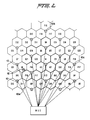
- Fig. 1 is a schematic diagram illustrating ten cells, C1 to C10, in a cellular mobile radio system. Normally the method according to the present invention would be implemented in a cellular mobile radio system comprising many more cells than ten. For purposes of this discussion, the system depicted herein is considered to be an isolated piece of a larger system which has been fragmented.
- Fig. 1 illustrates base stations situated in the vicinity of cell center and having omni-directional antennas.
- the base stations of adjacent cells may however be collocated in the vicinity of cell borders and have directional antennas.
- Fig. 1 also illustrates ten mobile stations, M1 to M10, which are movable within a cell and from one cell to another cell.
- the method according to the present invention may be implemented in a cellular mobile radio system comprising many more mobile stations than ten. In particular, there are normally many more mobile stations than there are base stations.
- a mobile switching center is also illustrated in Fig. 1 .
- the mobile switching center MSC illustrated in Fig. 1 is connected to all ten illustrated base stations by cables.
- the mobile switching center is connected by cables also to a fixed public switching telephone network or similar fixed network with ISDN facilities. All cables from the mobile switching center to base stations and cables to the fixed network are not illustrated. Further, other means may be used instead of cables for base to mobile switching center communications, e.g., fixed radio links.
- the cellular mobile radio system illustrated in Fig. 1 includes a plurality of radio channels for communication.
- the system is designed both for analog information, e.g., speech, digitized analog information, e.g., digitized speech, and pure digital information, e.g., pure digital data.
- connection is used for a communication channel between two telephones or terminals where at least one of the telephones or terminals may be using a radio/ cellular system.
- a connection may be a call where two people talk to each other, but may also be a data communication channel where computers exchange data.
- Each cellular system is assigned a particular frequency band on which it can operate.
- a set of communication channels is allocated to each cell. For example, between 10 and 30 different voice channels and 1 control channel may be allocated to any given cell. Different sets of communication channels must always be allocated to neighboring cells, since in order to maintain full radio coverage, cells overlap each other. Using the same channels would cause co-channel interference in these overlapping areas.
- FIG. 2 illustrates an example of a cluster pattern which is commonly used in mobile cellular telephone systems.
- a cluster of 21 cells is shown in thick lines.
- the letters used in the cell identification identify cells assigned to a common base station, while the numbers identify the cell number in the cluster and the frequencies assigned to the cell.
- the base stations 10 each serve three cells and are provided with directional antennas. It is also possible that each cell includes its own base station formed by an omni-directional antenna.
- FIG. 3 shows an example of several clusters of 21 cells each.
- Base stations 10' are connected to mobile switching center MSC V1
- base stations 10" are connected to a second mobile switching center MSC V2.
- These two mobile switching centers are in turn connected to a home location register/mobile switching center MSC HOME.
- the home location register/mobile switching center MSC HOME stores the record of the location of the mobile stations.
- Each mobile station is identified by a unique mobile station number. This mobile station number is sent by the mobile station to the base station and then to the mobile switching center. This number is also used by the mobile switching center during the paging of a mobile station.
- Each base station can also be identified by a digital color code. The digital color code is transmitted by the mobile station on a radio channel used for digital radio channels and serves to identify to the base station which base station transmitter the mobile station is receiving.
- FIG. 4 an embodiment of a mobile station that can be utilized in a cellular telephone system that operates in accordance with the present invention is illustrated.
- This particular example pertains to a mobile station that can be used in a digital communications system, i.e., one in which digitized voice information is transmitted between base and mobile stations.
- a digital communications system i.e., one in which digitized voice information is transmitted between base and mobile stations.
- the operation of the system is explained in the context of full-rate transmissions, in which each packet of digital information is interleaved over two spaced time slots in a frame of data.
- the invention is equally applicable to other types of cellular radio systems, such as those in which information is transmitted in an analog format or transmitted digitally at a half rate.
- a speech coder 101 converts the analog signal generated by microphone into a binary data stream.
- the data stream is then divided into data packets, according to the TDMA principle.
- a fast associated control channel (FACCH) generator 102 generates control and supervision signalling messages that are transmitted from the mobile station to the land-based system.
- the FACCH message replaces a user frame (speech/data) whenever it is to be transmitted.
- a slow associated control channel (SACCH) generator 103 provides signalling messages that are transmitted over a continuous channel for the exchange of information between the base station and the mobile station and vice-versa.
- a fixed number of bits, e.g. twelve, is allocated to the SACCH for each time slot of a message train.
- Channel coders 104 are respectively connected to the speech coder 101, FACCH generator 102, and SACCH generator 103 for manipulating the incoming data in order to carry out error detection and correction.
- the techniques used by the channel coders 104 are preferably convolutional encoding, which protects important data bits in the speech code, and cyclic redundancy check (CRC), wherein the perceptually significant bits in the speech coder frame, e.g. twelve bits, are used for computing a seven-bit check.
- CRC cyclic redundancy check
- a two-burst interleaver 106 is connected to the channel coder 104 associated with the speech coder 101 and the FACCH generator 102, respectively.
- the two-burst interleaver 106 is controlled by a microprocessor controller 130 so that, at appropriate times, user information over a particular speech channel is replaced with system supervision messages over the FACCH.
- Data to be transmitted by the mobile station is interleaved over two distinct time slots.
- a packet of 260 data bits, which constitute one transmitting word, are divided into two equal parts and are interleaved over two different time slots. The effects of RAYLEIGH fading is reduced in this manner.
- the output of the two-burst interleaver 106 is provided to the input of a modulo-two adder 107 so that the transmitted data is ciphered bit-by-bit by logical modulo-two-addition of a pseudo-random bit stream.
- the output of the channel coder 104 associated with the SACCH generator 103 is connected to a 22-burst interleaver 108.
- the 22-burst interleaver 108 interleaves data transmitted over the SACCH over 22 time slots each consisting of 12 bits of information.
- the mobile station further includes a Sync Word/DVCC generator 109 for providing the appropriate synchronization word (Sync Word) and DVCC (digital verification color code) which are to be associated with a particular connection.
- Sync Word is a 28-bit word used for time slot synchronization and identification.
- the DVCC is an 8-bit code which is sent by the base station to the mobile station and vice-versa, for assuring that the proper channel is being decoded.
- a burst generator 110 generates message bursts for transmission by the mobile station.
- the burst generator 110 is connected to the outputs of the modulo-two-adder 107, the 22-burst interleaver 108, the Sync Word/DVCC generator 109, an equalizer 114, and a control channel message generator 132, to integrate the various pieces of information from these respective units into a single message burst.
- a message burst comprises data (260 bits), SACCH (12 bits), Sync Word (28 bits), coded DVCC (12 bits), and 12 delimiter bits, combined for a total of 324 bits.
- control channel message bursts from the control channel message generator 132 and voice/traffic message bursts.
- the control channel message replaced the SACCH as well as the speech data normally generated in a voice/traffic burst.
- the transmission of a burst which is equivalent to one time slot, is synchronized with the transmission of other time slots, which together make up a frame of information.
- a frame comprises three full-rate time slots.
- the transmission of each burst is adjusted according to timing control provided by the equalizer 114. Due to time dispersion, an adaptive equalization method such as that described in detail in U.S. Patent Application No. 315,561, filed February 27, 1989, and assigned to the same assignee, is provided in order to improve signal quality.
- the base station functions as the master and the mobile station is the slave with respect to frame timing.
- the equalizer 114 detects the timing of an incoming bit stream from the base station and synchronizes the burst generator 110.
- the equalizer 114 is also operable for checking the Sync Word and DVCC for identification purposes.
- a frame counter 111 is coupled to the burst generator 110 and the equalizer 114.
- the frame counter 111 updates a ciphering code utilized by the mobile station for each transmitted frame, e.g., once every 20 ms.
- a ciphering unit 112 is provided for generating the ciphering code utilized by the mobile station. A pseudo random algorithm is preferably utilized.
- the ciphering unit 112 is controlled by a key 113 which is unique for each subscriber.
- the ciphering unit 112 consists of a sequencer which updates the ciphering code.
- the burst produced by the burst generator 110, which is to be transmitted, is forwarded to an RF modulator 122.
- the RF modulator 122 is operable for modulating a carrier frequency according to the ⁇ /4- DQPSK method ( ⁇ /4 shifted, Differentially encoded Quadrature Phase Shift Keying).
- the use of this technique implies that the information is differentially encoded, i.e., 2-bit symbols are transmitted as four possible changes in phase: ⁇ /4 and ⁇ 3 ⁇ /4.
- the transmitter carrier frequency supplied to the RF modulator 122 is generated by a transmitting frequency synthesizer 124 in accordance with the selected transmitting channel.
- the carrier is amplified by a power amplifier 123.
- the RF power emission level of the amplifier is selected on command by a microprocessor controller 130.
- the amplified signal is passed through a time switch 134 before it reaches the antenna. The timing is synchronized to the transmitting sequence by the microprocessor controller 130.
- a receiver carrier frequency signal is generated in accordance with the selected receiving channel by a receiving frequency synthesizer 125.
- Incoming radio frequency signals are received by a receiver 126, after passing through the time switch 134.
- the timing is synchronized to the receiving sequence by the microprocessor controller 130.
- the strength of the received signals are measured by a signal level meter 129.
- the received signal strength value is then sent to the microprocessor controller 130.
- An RF demodulator 127 which receives the receiver carrier frequency signal from the receiving frequency synthesizer 125 and the radio frequency signal from the receiver 126, demodulates the radio frequency carrier signal, thus generating an intermediate frequency.
- the intermediate frequency signal is then demodulated by an IF demodulator 128 which restores the original ⁇ /4-DQPSK - modulated digital information.
- the restored digital information provided by the IF demodulator 128 is supplied to the equalizer 114.
- a symbol detector 115 converts the received two-bit symbol format of the digital data from the equalizer 114 to a single-bit data stream. The symbol detector 115 in turn produces three distinct output signals.
- Control channel messages are sent to a control message detector 133 which supplies detected control channel information to the microprocessor controller 130.
- Any speech data/FACCH data is supplied to a modulo-two adder 107 and a two-burst deinterleaver 116.
- the speech data/FACCH data is reconstructed by these components by assembling and rearranging information from two time slots of the received data.
- the symbol detector 115 supplies SACCH data to a 22-burst deinterleaver 117.
- the 22-burst deinterleaver 117 reassembles and rearranges the SACCH data, which is spread over 22 consecutive frames.
- the two-burst deinterleaver 116 provides the speech data/FACCH data to two channel decoders 118.
- the convolutionally encoded data is decoded using the reverse of the above-mentioned coding principle.
- the received cyclic redundancy check (CRC) bits are checked to determine if any error has occurred.
- the FACCH channel coder furthermore detects the distinction between the speech channel and any FACCH information, and directs the decoders accordingly.
- a speech decoder 119 processes the received speech data from the channel decoder 118 in accordance with a speech coder algorithm (e.g., VSELP), and generates the received speech signal.
- the analog signal is finally enhanced by a filtering technique. Messages on the fast associated control channel are detected by a FACCH detector 120, and the information is transferred to the microprocessor controller 130.
- the output of the 22-burst deinterleaver 117 is provided to a separate channel decoder 118. Messages on the slow associated control channel are detected by a SACCH detector 121, and that information is transferred to the microprocessor controller 130.
- the microprocessor controller 130 controls the mobile station activity and the base station communication, and also handles the terminal keyboard input and display output 131. Decisions by the microprocessor controller 130 are made in accordance with received messages and measurements that are made.
- the keyboard and display unit 131 enable information to be exchanged between the user and the base station.
- Fig. 5 illustrates an embodiment of a base station that can be utilized in a cellular telephone system that operates in accordance with the present invention.
- the base station incorporates numerous component parts which are substantially identical in construction and function to component parts of the mobile station illustrated in Fig. 4 and described in conjunction therewith.
- Such identical component parts are designated in Fig. 5 with the same reference numerals utilized hereinabove in the description of the mobile station, but are differentiated therefrom by means of a prime (') designation.
- the base station has two receiving antennas. Associated with each of these receiving antennas are a receiver 126', an RF demodulator 127', and an IF demodulator 128'. Furthermore, the base station does not include a user keyboard and display unit 131 as utilized in the mobile station. Finally, there can be a plurality of channels, represented in Fig. 5 by the boxes labeled 1, 2 and 3, with corresponding inputs IN1, IN2, and IN3, and outputs OUT1, OUT2 and OUT3. Although the system is shown here with three channels, the number used would be dependent upon system requirements as determined by the system designers.
- the microprocessor controller 130 executes an initialization procedure. Initially, the serving system parameters are retrieved, meaning that the preferred system, e.g., A or B (wireline or non-wireline), is selected. Depending on the choice made, scanning is carried out over the dedicated control channels belonging to the preferred system.
- the preferred system e.g., A or B (wireline or non-wireline).
- the mobile station In order to tune the "best" control channel, the mobile station must search through the existing control channels. This is called scanning of control channels. Scanning can be started because the mobile station logic unit automatically inserts the first control channel number into the frequency generator in a known manner. The control channel with the strongest signal strength is chosen by the mobile to receive the call or other transmission.
- Fig. 6 is a block diagram of an example of a mobile switching center which can be used to implement the method according to the present invention.
- the mobile switching center shown in Fig. 6 is a simplified block diagram of some of the functional units in a mobile switching center.
- Fig. 6 shows but one example of a mobile switching center. Other systems may also be used.
- the mobile switching center 70 is a highly modular system which includes a central processor 72 and a mobile telephone subsystem 74 for the cellular system which is integrated with the other subsystems.
- a group switching subsystem 76, a common channel signalling subsystem 78, and a trunk and signalling subsystem 80 are connected to the central processor 72.
- the mobile telephone subsystem 74 includes a regional processor 82, a mobile telephone base station line terminal 84 and a signalling terminal 86.
- the remaining subsystems also each include a regional processor 82.
- the mobile telephone subsystem 74 handles all specific mobile subscriber functions, cellular network functions, as well as the signalling with the mobile stations. Subsystem 74 also provides the common channel signalling subsystem 78 with the necessary data from the mobile switching center signalling. The operation and maintenance functions specific for the cellular system are also implemented in the mobile telephone subsystem 74.
- the mobile telephone subsystem 74 includes the mobile telephone base station line terminals 84 which connect the mobile telephone subsystem 74 to the various base stations within the system and to the public switching telephone network.
- the signalling terminal 86 provided in the mobile telephone subsystem 74 handles data communication between the mobile switching center and the base stations.
- the regional processor 82 provided in each of the subsystems stores and executes the regional software for the switching system, handling simple, routine and high capacity tasks.
- the group switching subsystem 76 is controlled by a traffic control subsystem (not shown).
- the group switching subsystem 76 sets up, supervises and clears connections through the group switch (not shown).
- the common channel signalling subsystem 78 contains functions for signalling, routing, supervision and correction of messages sent in accordance with a predetermined standard.
- the trunk and signalling subsystem 80 supervises the state of the trunk lines to the public switching telephone network and to the other mobile switching centers.
- the central processor 72 stores and executes the central processor software for the switching system, handling the more complex functions. These functions include, but are not limited to, job administration, store handling, loading and changing of programs, etc. Further, to the extent that the methods according to the preferred embodiments of the present invention are implemented by software routines operating in the mobile switching center, they are implemented in the central processor 72.
- One of the primary tasks performed in the system access mode of the mobile station is the generation of an access message in the mobile station and preparation of a suitable traffic channel for information exchange.
- the access channels available to the mobile which were updated during an idle mode, are examined in a manner similar to the measuring of the dedicated control channels as previously described. A ranking of the signal strength of each is made, and the channel associated with the strongest signal is chosen.
- the transmitting frequency synthesizer 124 and the receiving frequency synthesizer 125 are tuned accordingly, and a service request message is sent over the selected channel in order to inform the base station about the type of access wanted, e.g., call origination, page response, or registration access.
- the amplifier 123 of the mobile station is turned off and the mobile station may wait for further control messages. Depending on the access type, the mobile station may then receive a reply message from the base station.
- a "wait and compare" method is used. This method is most applicable to the setting up of calls, both mobile originated calls and calls directed to mobile stations, although it can be used to process other types of mobile generated transmissions such as registrations.
- the following discussion referring to Fig. 2, relates to an example wherein a mobile station 12 travels from cell C8 to the nearby cell F16.
- the intended near base station 10a at the borders of nearby cells F16, F17 and F18
- the overhearing relatively faraway base station 10c at the borders of remote cells F16, F17, and F18
- the "wait and compare" method of the present invention involves waiting until the time has elapsed for all possible mobile generated transmissions originating from one mobile station (in this example 2 requests) to have come to the mobile switching center (i.e., using a time period which is approximated to be the worst-case time required for signalling), and to make a decision then as to which transmission to serve, rejecting all others. This decision is based on the signal strength if the difference therebetween is significant. If this difference is not significant, the determination as to which transmission to use as made based on some other predefined priority order, such as the first transmission to be received.
- One possible threshold value for the difference could be about 10dB, but this threshold could be differently specified for each system or each cell or even each cell-cell combination. According to a preferred embodiment, the threshold is between ⁇ 10dB.
- a compensation value is added to each of the received signal strengths (compensation values being an individual cell parameter) to make it possible to change the odds for some cells to win the comparison competition.
- the value of the compensation parameter could be initially set to 0. It can later be changed if experience, simulations, etc. show that some cells fail in comparisons when they should win. This situation could occur, for example if the faraway base station has very good receiving conditions, e.g., is situated in a high tower on a mountain.
- the compensation values are determined based on each particular cell-cell combination and can be altered as experience dictates.
- the compensation could be accomplished after the difference is determined by adding a value to the difference between the signal strengths.
- the mobile station scans the control channels from nearby base stations and selects the strongest signal strength, at step 200.
- the mobile station then waits for some control signal over the selected control channel (step 202). If nothing intended for the mobile station is heard, when it is again time to rescan the control channels to determine which is the strongest (step 204), the mobile station returns to step 200.
- the mobile may determine: it is time to register (step 206); it wants to make a call (step 208); it has received a page and wants to respond (step 210); or it received an audit message and wants to answer (step 212).
- Other functions are possible, as is known to technical people working in cellular technology, but are not described herein because they are not relevant to the present invention.
- the mobile For each action that will be taken in steps 206-212, the mobile performs a system access by scanning and selecting the strongest control channel at step 214. At step 216, the mobile sends the mobile generated transmission to the selected control channel.
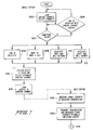
- both the intended base station and any other base stations operating on the same or adjacent frequencies which overhear the mobile generated transmission (called “transmission” in the drawings for simplicity) measure the signal strength of the received mobile generated transmission at step 218. That transmission is then transmitted along with the measured signal strength, to the mobile switching center at step 220. At this point, control is passed to step 300, shown in Fig. 8.
- All mobile generated transmissions reported to the mobile switching center with the same mobile station number and/or serial number within the given time period are stored in the mobile switching center at step 300.
- the identity of the appropriate mobile station and base station or an area associated with the base station, the signal strength of the received signal, and the time of receipt of the mobile generated transmission by the mobile switching center are also stored.
- the compensated signal strengths stored for the stored transmissions are compared to one another.
- the mobile generated transmission to be chosen as the correct transmission is determined according to a second priority order, at step 310.
- the first mobile generated transmission to be received is processed.
- Step 311 is executed if only one mobile generated transmission is received (yes, at step 309) so that the only received transmission is processed.
- the decision concerning which mobile generated transmission to process is made in the mobile switching center.
- both mobile switching centers may attempt to send the mobile generated transmission to a home location register or home mobile switching center.
- the home location register or home mobile switching center then makes the decision at to which based station is the intended recipient of the message.
- the software routines illustrated in Fig. 8 would be executed in a processor connected to the home location register, either a stand-alone processor or one which also serves as a mobile switching center processor.
- the time period of Fig. 8 is measured by a clock.
- This clock may be for example, an internal clock (not shown) in the mobile switching center or home location register.
- the time period begins upon the occurrence of the first event, i.e., when the first transmission from a given mobile unit is received, through the base station, by the mobile switching center.
- the time period during which the transmissions are stored may be in the range of 100 ms or less, depending on, among other things, the signalling used (protocol, transmission speed, load, etc) between the base station and the mobile switching center. If several mobile switching centers are involved, the time period may be in the range of up to about 2 seconds or less, depending on, among other things, the signalling used (protocol, transmission speed, load, etc.) between the mobile switching centers.
- a "store and compare” method is used. This method is most applicable to the registering of a mobile unit in a new cell, although it can be used for processing other mobile generated transmissions, such as access requests or paging responses.
- the following discussion relates to an example where the mobile unit travels from cell C8 to the nearby cell F16. Also, though this is not necessary, the location (or area) border passes between these two cells.
- the mobile unit recognizes the need to register when reading the SID (the digital system identification associated with a cellular system; each system being assigned a unique number) or the REGID (the registration identification) in the overhead message train (in cellular systems), and makes an access for registration.
- SID the digital system identification associated with a cellular system; each system being assigned a unique number
- REGID the registration identification
- the access is reported to the respective mobile switching center by the nearby F16 base station 10a and by the faraway F16 base station 10c, connected to the same mobile switching center. It is assumed that all mobile generated transmissions received by the mobile switching center within a predetermined time after the first received transmission relate to the same request, overheard by more than one base station.
- the "store and compare” method will now be described with reference to Figs. 7 and 9.
- the processing carried out by the mobile station engaged in registration and by the receiving base stations is the same as shown in Fig. 7 and described above with respect to the "wait and compare” method.
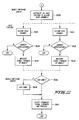
- the mobile switching center records the first incoming mobile generated transmission together with the signal strength measured by the nearby base station 10a during the access at step 400 of Fig. 9.
- the next mobile generated transmission arrives, it is first determined whether the next transmission arrived within a specified time limit at step 402.
- the time used for the specified time limit is typically less than 2 seconds, as discussed above with respect to the "wait and compare" method. With other possible system configurations, the time limit may range up to about 10 seconds or more.
- the signal strength measured by the faraway F16 base station 10c is compared to the previously recorded signal strength to calculate a difference therebetween (step 404).
- compensation values may be added to the signal strengths themselves, before the difference is calculated, as described above with respect to Fig. 8.
- step 410 It is determined at step 410 whether the difference between the two signal strengths is above a specified limit. If the difference is above the limit, that is, the difference is significant, the previously received mobile generated transmission is replaced by the new transmission at step 412. Further, if the next transmission is not within the specified time limit at step 402, the new transmission is processed at step 412. In either case, the base station is then informed of the outcome of the mobile generated transmission processing (step 414).
- the mobile switching center acts on the first access that it receives, and stores the identification of the mobile and base stations, the signal strength of the access request and the time it was received. If another access from the same mobile station number and/or serial number is received within a short time from the first access, a comparison is made between the accesses after the aforementioned compensation value has been added to the received signal strength. If the second access is lower in signal strength, it is rejected. Otherwise, it is acted upon, replacing the first access. The processing of the first base station's access in the case of a second higher signal strength will be terminated. A negative acknowledgement may also be sent to the mobile station via the base station in question.
- Successive mobile station accesses withing a short time frame from the first access will be likewise compared relative to their signal strength.
- a negative acknowledgement signal may be sent back to the mobile station via the base station in question and may be counted for statistical purposes.
- the overhearing base stations may be assigned to different mobile switching centers.
- the processing of Fig. 9 can occur in a home location register or a home mobile switching center to which both mobile switching centers are connected.
- mobile station access refers to any type of system access a mobile station may make when contacting a base station.
- the invention has been described with reference to a system including a mobile switching center, this is not intended to be limited to such applications. If no mobile switching center is present, the process described above for determining which of several accesses is correct would be carried out in the base stations. Likewise, the process could be modified to accommodate more than one mobile switching center as may occur in systems such as that shown in Fig. 3 and discussed above.
- HLR Home Location Register database
- the methods of the present invention can be used in a cellular mobile radio system which transmits analog signals, digital signals, or a combination of both.
Description
- The present invention relates to cellular mobile radio systems. More particularly, the present invention is directed to a method and apparatus for processing access requests, paging responses, or registration accesses from mobile stations to base stations in such a way as to eliminate erroneous processing which may occur under certain conditions. Such conditions include the situation that arises when base stations not intended to handle a particular access or paging response overhear the particular access or paging response and report it to the mobile switching center.
- A typical cellular mobile radio telephone system consists of at least one mobile switching center (also known as a mobile telephone switching office), at least one base station, and at least one mobile station. The mobile switching center constitutes an interface between the radio system and the public switching telephone network. The base station transmits information between the mobile stations and the mobile switching center. Calls to and from mobile subscribers are switched by the mobile switching center. The mobile switching center also provides all signalling functions needed to establish the calls.
- In order to obtain radio coverage of a geographical area, a number of base stations are normally required. This number may range from, in the exceptional case, one base station, and up to one hundred or more base stations in normal systems. The area is divided into cells, where each cell may either be serviced by a base station or may share a base station with a number of the other cells. Each cell has an associated control channel over which control (non-voice) information is communicated between the mobile units in that cell and the base station. Generally speaking, the control channel includes a dedicated channel at a known frequency over which certain information is communicated from the base station to mobile stations, a paging channel for unidirectional transmissions of information from the base station to the mobile stations, and an access channel for bidirectional communications between the mobile stations and the base station. These various channels may share the same frequency, or they may operate at different respective frequencies.
- Each mobile station is assigned to one mobile switching center or home location register. The home location register is a database which contains information about all its assigned subscribers and where they are in the network. The home location register can be a stand-alone intelligent processor connected to one or more mobile switching centers or it can be part of a mobile switching center, possibly connected to one or more other mobile switching centers. When a mobile station enters a second mobile switching center service area to which it is not assigned, the new exchange is regarded as a visited exchange, and the subscriber as a visiting subscriber. Calls are now routed to and switched in this second mobile switching center.
- Three types of transmissions normally take place on the control channels between the mobile stations and the base station, although other types are possible, such as an audit request and response, or order confirmation. First, when a mobile station is originating a call, it sends an access request to the base station the control channel of which has the strongest or second strongest signal. This access request serves to inform the base station that the requesting mobile needs to be assigned a voice channel over which the call can be connected. Second, when a mobile station is paged by a base station, indicating that the base station has a call to be completed to the mobile subscriber, the paged mobile station sends back a paging response on the access channel. Finally, when a mobile station travels from one cell to another, or for other reasons, the mobile station may send a registration access to identify itself and its presence to the telephone exchange associated with the cell.
- An originating call access or a paging response is performed as follows. The mobile station scans the control channels of surrounding base stations and selects the one with the strongest or second strongest signal over which to make the access. The mobile station then performs the access by sending a transmission on the reverse control channel to the associated base station. The associated base station then passes the access or paging response to its mobile switching center.
- A registration access is performed in cellular systems as follows. A registration access is an access requested by a mobile station to identify itself to a base station as being active in the system at the time the message is sent to the base station. The registration access may be requested for a number of reasons, for example: the mobile is switched on; the mobile determines that the time elapsed since the last registration has passed a specified limit; or the mobile detects a different system or area identification (SID or AID). The mobile then scans the control channels of surrounding base stations, and selects the one with the strongest or second strongest signal on which to complete the registration access, as explained above regarding call origination. The associated base station then passes the registration access to its mobile switching center.
- For simplicity in the following discussion, an access request, paging response, and registration access of the type described above may be referred to as a mobile generated transmission when the discussion pertains to all three types.
- Due to unfavorable (low) attenuation between remote base stations and mobile stations, it is possible that two or more base stations will receive a mobile generated transmission while only one base station is actually the intended recipient. In other words, it is possible that a mobile generated transmission which is intended for a given base station may be overheard by another base station operating on the same, or an adjacent, frequency. The risk of this increases as the number of cells, or base stations, in a given region increases to handle the increasing number of mobile stations.
- Normally, protection codes are used which prevent the second base station from inadvertently overhearing the mobile generated transmission. However, there is only a small number of unique codes. Therefore, there is a good chance that various base stations may overhear mobile generated transmissions which are intended for other base stations. Conventional base stations are not capable of reliably determining whether such transmissions are actually intended for themselves or for other base stations.
- In such cases, each of the base stations will try to act on the transmission received from the mobile station and will therefore notify the mobile switching center of a mobile generated transmission. Because two or more such transmissions are thus sent to the mobile switching center, the mobile switching center cannot accurately determine which of the mobile generated transmissions to accept and further process. Processing the mobile generated transmission received first in time is not necessarily correct because the transmission from the base station which was not intended to receive the mobile generated transmission may reach the mobile switching center first.
- In one known system described in U.S. Patent No. 4,481,670 to Freeburg, where more than one channel communication modules CCM receives an access request from a mobile, a general communications controller GCC is called upon to determine which CCM to use as the primary station. In this system described in this patent, the area is divided into seven zones, where each zone is covered by one or more transmitter/receiver pair. Each time a mobile transmits, signal strength readings are taken by each receiver hearing the transmission. These readings are used to compute an adjusted signal strength for each zone by multiplying the measured signal strengths for each zone by preselected factors associated with the particular zone. The GCC then selects the zone which has the largest adjusted signal strength for a particular transmission from the mobile as being the zone in which the mobile is most likely located. The selected zone is then stored for later reference when it becomes necessary to locate the mobile.
- Whenever a message signal together with an average signal strength measurement is received by the GCC from a CCM, a message timer is set to provide a time interval during which the same message signal is received by other CCM's and sent together with an average signal strength measurement to the GCC. All signals from other CCM's received within the set time period are used to determine where the mobile is located. Thus, the location of each mobile is updated each time a message signal is received by the CCMS. Then, when it is desired to transmit a message signal for the GCC to a selected mobile, the most recently determined location is used as a first try for successful connection.
- According to this patented method, the system described in the patent appears to be one in which adjacent CCM's operate on the same frequencies, thus permitting adjacent CCM's to hear the same message from a mobile. Further, only the largest adjusted signal strength is used, with no provision for the possibility that two signal strengths may be so close as to preclude an accurate determination. Finally, by multiplying the signal strength measurements by predetermined factors, inaccurate determinations of locations are possible.
- Other systems are known for handling mobile generated transmissions received at more than one base station. U.S. Patent No. 4,144,412 to Ito et al. describes a mobile communication system in which a mobile generated transmission is received at base stations. A signal representing the intensity of the received signal is added to the received signal, and the sum is sent to a radio control unit for processing. This information is stored in a memory in the control unit. The base station that has received the wave maximum intensity is determined, and a search is made to determine whether there is an idle speech channel in that base station. If not, another base station that has received a signal having the intensity next to the maximum is determined, and a search is made to determine whether that station has an idle channel. When an idle speech channel is available a processing operation proceeds.
- European Patent Application No. 0283683 to Yamauchi et al. describes a mobile communication system in which signal strengths of call initiations received at different base stations are compared. From this comparison, it is determined which base station should respond to a call.
- Both of these systems suffer from the problems discussed above, namely that there is no provision for handling a situation where two signal strengths may be so close as to preclude an accurate determination of which base station should handle the call.
- In some conventional systems, the mobile switching center automatically starts processing of the first mobile generated transmission. However, in certain circumstances, this may not be appropriate and may result in lost calls. For example, consider the case when a mobile station makes an access in a network where adjacent base stations operate on different frequencies. Because the receivers in the control channels are not normally receiving any informative signals, distant control channel picks up a weak whisper of this access from far away. The base station with which this distant control channel is associated then sends this weak access to the mobile switching center. The weak access, because it occurs first in time is processed. Thereafter, if the intended base station forwards the access request it has received, the call is lost because the mobile switching center has reacted to the first received request and therefore ignores the second.
- In order to overcome the disadvantages noted with conventional systems, the present invention is directed to a method of operating a cellular radio telephone system for determining which transmission, received by a mobile switching center from at least two base stations receiving a single mobile initiated transmission should be accepted by the mobile switching center, the method including the steps of, measuring the signal strength of the received mobile generated transmission, sending the mobile generated transmission and the measured signal strength of the mobile generated transmission to a processing means from the at least two base stations, storing in a memory the respective mobile generated transmissions and measured signal strengths received from the at least two base stations within a predetermined time period, and determining which of the mobile generated transmissions to accept based on time of receipt by the processing means and the stored signal strengths of the mobile generated transmissions. The step of determining comprises the steps of comparing the signal strengths to yield a difference value, if the difference value exceeds a predetermined threshold, accepting the mobile generated transmission having the strongest relative signal strength, and if the difference value is below the predetermined threshold, accepting one of the received mobile generated transmissions according to a predetermined priority order. The step of determining further comprises the step of adding a stored compensation value to each of the measured signal strengths received from the at least two base stations to determine compensated signal strengths, the compensation value being stored relative to each pair of base stations of the at least two base stations, wherein the step of comparing comprises comparing the compensated signal values to yield a difference value.
- According to another preferred embodiment of the present invention, a method of operating a cellular system is provided, wherein a mobile station transmits a mobile generated transmission which is received by at least two base stations. The method comprises the steps of processing the mobile generated transmission received first from one of the base stations, storing the identification of the base station from which the processed mobile generated transmission originated and the signal strength of the processed mobile generated transmission, comparing the signal strength of a subsequent mobile generated transmission received from another base station to the signal strength of the processed mobile generated transmission to yield a difference value, obtaining a compensated difference value by adding a compensation value stored relative to the base stations from which the processed mobile generated transmission and the subsequent mobile generated transmission are received, when the compensated difference value is greater than or equal to a predetermined threshold amount, terminating the processed mobile generated transmission, processing. the subsequent mobile generated transmission having the greater signal strength, and storing the identification of the base station from which the subsequent processed mobile generated transmission originated and the signal strength of the subsequent processed mobile generated transmission, and repeating the comparing, terminating and subsequent processing and storing steps for further mobile generated transmissions received during a set time period.
- According to another preferred embodiment of the present invention, a method is provided of operating a cellular system, wherein a mobile station transmits a mobile generated transmission which is received by at least two base stations. The method comprises the steps of:
- (a) in the mobile station:
- (1) scanning a plurality of control channels over which messages are broadcast by a plurality of base stations to determine relative signal strengths of the messages,
- (2) sending a mobile generated transmission over a selected one of said plurality of control channels, the mobile generated transmission being received by the at least two base stations,
- (b) in the at least two base stations performing the steps of:
- (1) measuring the signal strength of the received mobile generated transmission,
- (2) sending the mobile generated transmission and the measured signal strength of the received mobile generated transmission to the processing means,
- (c) in the processing means performing the steps of;
- (1) storing in a memory the respective mobile generated transmissions and measured signal strengths received from the at least two base stations within a predetermined period - of time, and
- (2) determining which of the received mobile generated transmissions to accept based on the time of receipt in the processing means and the relative signal strengths of the mobile generated transmissions.
- The step of determining comprises the steps of adding a stored compensation value to each of the measured signal strengths received from the at least two base stations to determine compensated signal strengths, the compensation value being stored relative to each pair of base stations of the at least two base stations, comparing the compensated signal strengths to yield a difference value, if the difference value exceeds a predetermined threshold, accepting the mobile generated transmission having the strongest relative signal strength, and if the difference value is below the predetermined threshold, accepting one of the received mobile generated transmissions according to a predetermined priority order.
- According to a preferred embodiment of the invention, a system is provided for processing multiple mobile generated transmissions in a cellular system, the cellular system having at least one mobile unit, at least two base stations and at least one processing means. The system comprises means provided in the mobile unit for scanning signals transmitted by such base stations on at least one base to mobile control channel and selecting one of the base stations for access, means provided in the mobile unit for transmitting the mobile generated transmissions over a control channel of the selected base station, means provided in the at least two base stations for receiving the transmitted mobile generated transmissions and for sending the received mobile generated transmissions to the processing means, and means provided in the processing means for selecting one of the several mobile generated transmissions received from the at least two base stations for processing based on the time of receipt of the mobile generated transmission and the relative signal strength of the mobile to base signal associated with the mobile generated transmissions, the means for selecting comprising memory means for storing the mobile generated transmissions which occur within a predetermined time period, identities of the mobile stations sending the mobile generated transmissions, signal strength of the mobile generated transmissions measured at the time of receipt of the mobile generated transmission by the respective base stations, means for measuring the signal strengths of the mobile generated transmissions, and comparing means for comparing the stored signal strengths of the transmissions to yield a difference value and comparing the difference value to a predetermined threshold, wherein said means for selecting is responsive to said comparing means to select a mobile generated transmission having the strongest relative signal strength when the difference value is greater than or equal to a predetermined threshold and accept another one of the received mobile generated transmissions according to a predetermined priority order when the difference value is below a predetermined threshold.
- The present invention will now be described in more detail with reference to the preferred embodiments of the device, given only by way of example, and with reference to the accompanying drawings, in which:
- Fig. 1 is a schematic diagram illustrating an example cellular mobile radio system illustrating the relationship of the system's cells, a mobile switching center, base stations, and mobile stations;
- Fig. 2 is a schematic diagram illustrating a number of clusters of 21 cells each, many cells being connected to the same mobile switching center;
- Fig. 3 is a schematic diagram illustrating a number of clusters of 21 cells each, a number of the cells being connected to one mobile switching center and another number of the cells being connected to a second mobile switching center, these two mobile switching centers being connected to a home mobile switching center;
- Fig. 4 is a block diagram illustrating a mobile station in a cellular mobile radio system according to Fig. 1;
- Fig. 5 is a block diagram illustrating a base station in a cellular mobile radio system according to Fig. 1;
- Fig. 6 is a block diagram illustrating a mobile switching center in a cellular mobile radio system according to Fig. 1;
- Fig. 7 is a flowchart of a pre-processing stage of the present invention;
- Fig. 8 is a flowchart illustrating a first embodiment of the present invention;
- Fig. 9 is a flowchart illustrating a second embodiment of the present invention; and
- Fig. 10 is a flowchart illustrating a third embodiment of the present invention.
- The present invention is applicable to the following situations. During initial setup of a communication between a mobile station and another mobile station or a telephone network, i.e., the mobile subscriber wants to place a call, the mobile station sends out an access request over a control channel of the closest base station. Additionally, when a mobile unit is being paged, i.e., the mobile unit is being sought when an incoming call is received by the base station, the mobile unit generates a paging response. Further, a mobile station may send a registration access when a predetermined time period has elapsed since the last registration access, or may send a registration access when the mobile station moves into a new cell. As stated above, the access request, paging response and registration access will be termed mobile generated transmissions for purposes of the following discussion.
- In certain cases, it is possible that these mobile generated transmission could be overheard by not only the intended base station, but by another base station or stations operating on the same or an adjacent channel or frequency. Each of the base stations receiving the mobile generated transmission will automatically process the mobile generated transmission by transmitting it to the mobile switching center. Additionally, it is possible that more than one mobile switching center will hear the transmissions from the base stations. In the former situation, the mobile switching center must make a choice as to which mobile generated transmission from the different base stations should be accepted. In the latter situation, a home location register must make the choice.
- The present invention is directed to methods for determining which of the received mobile generated transmissions is the proper one.
- When a mobile generated transmission appears in more than one base station, these transmissions will be detected all within a few milliseconds of one another in the various base stations. Both, or all, base stations will try to act on the transmission received from the mobile station by immediately notifying the mobile switching center. In order to make a comparison between mobile generated transmissions in the different base stations, all the mobile generated transmissions received within a given relatively short period of time are stored to allow for other base stations to report their mobile generated transmissions. The relative signal strengths of the mobile generated transmissions are compared to determine which of them is to be accepted.
- Fig. 1 is a schematic diagram illustrating ten cells, C1 to C10, in a cellular mobile radio system. Normally the method according to the present invention would be implemented in a cellular mobile radio system comprising many more cells than ten. For purposes of this discussion, the system depicted herein is considered to be an isolated piece of a larger system which has been fragmented.
- For each cell C1 to C10, there is a respective base station B1 to B10. Fig. 1 illustrates base stations situated in the vicinity of cell center and having omni-directional antennas. The base stations of adjacent cells may however be collocated in the vicinity of cell borders and have directional antennas.
- Fig. 1 also illustrates ten mobile stations, M1 to M10, which are movable within a cell and from one cell to another cell. The method according to the present invention may be implemented in a cellular mobile radio system comprising many more mobile stations than ten. In particular, there are normally many more mobile stations than there are base stations.
- Also illustrated in Fig. 1 is a mobile switching center. The mobile switching center MSC illustrated in Fig. 1 is connected to all ten illustrated base stations by cables. The mobile switching center is connected by cables also to a fixed public switching telephone network or similar fixed network with ISDN facilities. All cables from the mobile switching center to base stations and cables to the fixed network are not illustrated. Further, other means may be used instead of cables for base to mobile switching center communications, e.g., fixed radio links.
- The cellular mobile radio system illustrated in Fig. 1 includes a plurality of radio channels for communication. The system is designed both for analog information, e.g., speech, digitized analog information, e.g., digitized speech, and pure digital information, e.g., pure digital data. In the context of the present invention, the term connection is used for a communication channel between two telephones or terminals where at least one of the telephones or terminals may be using a radio/ cellular system. Thus a connection may be a call where two people talk to each other, but may also be a data communication channel where computers exchange data.
- Each cellular system is assigned a particular frequency band on which it can operate. A set of communication channels is allocated to each cell. For example, between 10 and 30 different voice channels and 1 control channel may be allocated to any given cell. Different sets of communication channels must always be allocated to neighboring cells, since in order to maintain full radio coverage, cells overlap each other. Using the same channels would cause co-channel interference in these overlapping areas.
- A group of neighboring cells using all the unique channels available in the system frequency band is called a cluster of cells. In other words, there is no frequency reuse in a cluster. Fig. 2 illustrates an example of a cluster pattern which is commonly used in mobile cellular telephone systems. For example, in the pattern of Fig. 2, a cluster of 21 cells is shown in thick lines. For illustration purposes, the letters used in the cell identification identify cells assigned to a common base station, while the numbers identify the cell number in the cluster and the frequencies assigned to the cell. Thus, cells in different clusters with the same numbers and letters transmit over the same frequencies. In the example shown in Fig. 2, the
base stations 10 each serve three cells and are provided with directional antennas. It is also possible that each cell includes its own base station formed by an omni-directional antenna. - It is not necessary that complete clusters be associated with the same mobile switching center. Fig. 3 shows an example of several clusters of 21 cells each. Base stations 10' are connected to mobile switching center MSC V1, and
base stations 10" are connected to a second mobile switching center MSC V2. These two mobile switching centers are in turn connected to a home location register/mobile switching center MSC HOME. The home location register/mobile switching center MSC HOME stores the record of the location of the mobile stations. - Each mobile station is identified by a unique mobile station number. This mobile station number is sent by the mobile station to the base station and then to the mobile switching center. This number is also used by the mobile switching center during the paging of a mobile station. Each base station can also be identified by a digital color code. The digital color code is transmitted by the mobile station on a radio channel used for digital radio channels and serves to identify to the base station which base station transmitter the mobile station is receiving.
- Referring now to Fig. 4, an embodiment of a mobile station that can be utilized in a cellular telephone system that operates in accordance with the present invention is illustrated. This particular example pertains to a mobile station that can be used in a digital communications system, i.e., one in which digitized voice information is transmitted between base and mobile stations. Furthermore, the operation of the system is explained in the context of full-rate transmissions, in which each packet of digital information is interleaved over two spaced time slots in a frame of data. It will be readily appreciated, however, that the invention is equally applicable to other types of cellular radio systems, such as those in which information is transmitted in an analog format or transmitted digitally at a half rate.
- In the mobile station depicted in Fig. 4, a
speech coder 101 converts the analog signal generated by microphone into a binary data stream. The data stream is then divided into data packets, according to the TDMA principle. A fast associated control channel (FACCH)generator 102 generates control and supervision signalling messages that are transmitted from the mobile station to the land-based system. The FACCH message replaces a user frame (speech/data) whenever it is to be transmitted. A slow associated control channel (SACCH)generator 103 provides signalling messages that are transmitted over a continuous channel for the exchange of information between the base station and the mobile station and vice-versa. A fixed number of bits, e.g. twelve, is allocated to the SACCH for each time slot of a message train.Channel coders 104 are respectively connected to thespeech coder 101,FACCH generator 102, andSACCH generator 103 for manipulating the incoming data in order to carry out error detection and correction. The techniques used by thechannel coders 104 are preferably convolutional encoding, which protects important data bits in the speech code, and cyclic redundancy check (CRC), wherein the perceptually significant bits in the speech coder frame, e.g. twelve bits, are used for computing a seven-bit check. - A two-
burst interleaver 106 is connected to thechannel coder 104 associated with thespeech coder 101 and theFACCH generator 102, respectively. The two-burst interleaver 106 is controlled by amicroprocessor controller 130 so that, at appropriate times, user information over a particular speech channel is replaced with system supervision messages over the FACCH. Data to be transmitted by the mobile station is interleaved over two distinct time slots. A packet of 260 data bits, which constitute one transmitting word, are divided into two equal parts and are interleaved over two different time slots. The effects of RAYLEIGH fading is reduced in this manner. The output of the two-burst interleaver 106 is provided to the input of a modulo-twoadder 107 so that the transmitted data is ciphered bit-by-bit by logical modulo-two-addition of a pseudo-random bit stream. - The output of the
channel coder 104 associated with theSACCH generator 103 is connected to a 22-burst interleaver 108. The 22-burst interleaver 108 interleaves data transmitted over the SACCH over 22 time slots each consisting of 12 bits of information. - The mobile station further includes a Sync Word/
DVCC generator 109 for providing the appropriate synchronization word (Sync Word) and DVCC (digital verification color code) which are to be associated with a particular connection. The Sync Word is a 28-bit word used for time slot synchronization and identification. The DVCC is an 8-bit code which is sent by the base station to the mobile station and vice-versa, for assuring that the proper channel is being decoded. - A
burst generator 110 generates message bursts for transmission by the mobile station. Theburst generator 110 is connected to the outputs of the modulo-two-adder 107, the 22-burst interleaver 108, the Sync Word/DVCC generator 109, anequalizer 114, and a controlchannel message generator 132, to integrate the various pieces of information from these respective units into a single message burst. For example, according to the published U.S. standard EIA/TIA 15-54, a message burst comprises data (260 bits), SACCH (12 bits), Sync Word (28 bits), coded DVCC (12 bits), and 12 delimiter bits, combined for a total of 324 bits. Under the control of themicroprocessor 130, two different types of message bursts are generated by the burst generator 110: control channel message bursts from the controlchannel message generator 132 and voice/traffic message bursts. The control channel message replaced the SACCH as well as the speech data normally generated in a voice/traffic burst. - The transmission of a burst, which is equivalent to one time slot, is synchronized with the transmission of other time slots, which together make up a frame of information. For example, under the U.S. standard, a frame comprises three full-rate time slots. The transmission of each burst is adjusted according to timing control provided by the
equalizer 114. Due to time dispersion, an adaptive equalization method such as that described in detail in U.S. Patent Application No. 315,561, filed February 27, 1989, and assigned to the same assignee, is provided in order to improve signal quality. Briefly, the base station functions as the master and the mobile station is the slave with respect to frame timing. Theequalizer 114 detects the timing of an incoming bit stream from the base station and synchronizes theburst generator 110. Theequalizer 114 is also operable for checking the Sync Word and DVCC for identification purposes. - A
frame counter 111 is coupled to theburst generator 110 and theequalizer 114. Theframe counter 111 updates a ciphering code utilized by the mobile station for each transmitted frame, e.g., once every 20 ms. Aciphering unit 112 is provided for generating the ciphering code utilized by the mobile station. A pseudo random algorithm is preferably utilized. Theciphering unit 112 is controlled by a key 113 which is unique for each subscriber. Theciphering unit 112 consists of a sequencer which updates the ciphering code. - The burst produced by the
burst generator 110, which is to be transmitted, is forwarded to anRF modulator 122. The RF modulator 122 is operable for modulating a carrier frequency according to the π/4- DQPSK method (π/4 shifted, Differentially encoded Quadrature Phase Shift Keying). The use of this technique implies that the information is differentially encoded, i.e., 2-bit symbols are transmitted as four possible changes in phase: ±π/4 and ±3π/4. The transmitter carrier frequency supplied to theRF modulator 122 is generated by atransmitting frequency synthesizer 124 in accordance with the selected transmitting channel. Before the modulated carrier is transmitted by an antenna, the carrier is amplified by apower amplifier 123. The RF power emission level of the amplifier is selected on command by amicroprocessor controller 130. The amplified signal is passed through atime switch 134 before it reaches the antenna. The timing is synchronized to the transmitting sequence by themicroprocessor controller 130. - A receiver carrier frequency signal is generated in accordance with the selected receiving channel by a
receiving frequency synthesizer 125. Incoming radio frequency signals are received by areceiver 126, after passing through thetime switch 134. The timing is synchronized to the receiving sequence by themicroprocessor controller 130. The strength of the received signals are measured by asignal level meter 129. The received signal strength value is then sent to themicroprocessor controller 130. AnRF demodulator 127, which receives the receiver carrier frequency signal from thereceiving frequency synthesizer 125 and the radio frequency signal from thereceiver 126, demodulates the radio frequency carrier signal, thus generating an intermediate frequency. The intermediate frequency signal is then demodulated by an IFdemodulator 128 which restores the original π/4-DQPSK - modulated digital information. - The restored digital information provided by the
IF demodulator 128 is supplied to theequalizer 114. Asymbol detector 115 converts the received two-bit symbol format of the digital data from theequalizer 114 to a single-bit data stream. Thesymbol detector 115 in turn produces three distinct output signals. Control channel messages are sent to acontrol message detector 133 which supplies detected control channel information to themicroprocessor controller 130. Any speech data/FACCH data is supplied to a modulo-twoadder 107 and a two-burst deinterleaver 116. The speech data/FACCH data is reconstructed by these components by assembling and rearranging information from two time slots of the received data. Thesymbol detector 115 supplies SACCH data to a 22-burst deinterleaver 117. The 22-burst deinterleaver 117 reassembles and rearranges the SACCH data, which is spread over 22 consecutive frames. - The two-
burst deinterleaver 116 provides the speech data/FACCH data to twochannel decoders 118. The convolutionally encoded data is decoded using the reverse of the above-mentioned coding principle. The received cyclic redundancy check (CRC) bits are checked to determine if any error has occurred. The FACCH channel coder furthermore detects the distinction between the speech channel and any FACCH information, and directs the decoders accordingly. Aspeech decoder 119 processes the received speech data from thechannel decoder 118 in accordance with a speech coder algorithm (e.g., VSELP), and generates the received speech signal. The analog signal is finally enhanced by a filtering technique. Messages on the fast associated control channel are detected by aFACCH detector 120, and the information is transferred to themicroprocessor controller 130. - The output of the 22-
burst deinterleaver 117 is provided to aseparate channel decoder 118. Messages on the slow associated control channel are detected by aSACCH detector 121, and that information is transferred to themicroprocessor controller 130. - The
microprocessor controller 130 controls the mobile station activity and the base station communication, and also handles the terminal keyboard input anddisplay output 131. Decisions by themicroprocessor controller 130 are made in accordance with received messages and measurements that are made. The keyboard anddisplay unit 131 enable information to be exchanged between the user and the base station. - Fig. 5 illustrates an embodiment of a base station that can be utilized in a cellular telephone system that operates in accordance with the present invention. The base station incorporates numerous component parts which are substantially identical in construction and function to component parts of the mobile station illustrated in Fig. 4 and described in conjunction therewith. Such identical component parts are designated in Fig. 5 with the same reference numerals utilized hereinabove in the description of the mobile station, but are differentiated therefrom by means of a prime (') designation.
- There are, however, some distinctions between the mobile and base stations. For instance, the base station has two receiving antennas. Associated with each of these receiving antennas are a receiver 126', an RF demodulator 127', and an IF demodulator 128'. Furthermore, the base station does not include a user keyboard and
display unit 131 as utilized in the mobile station. Finally, there can be a plurality of channels, represented in Fig. 5 by the boxes labeled 1, 2 and 3, with corresponding inputs IN1, IN2, and IN3, and outputs OUT1, OUT2 and OUT3. Although the system is shown here with three channels, the number used would be dependent upon system requirements as determined by the system designers. - When power is applied to the mobile station, the
microprocessor controller 130 executes an initialization procedure. Initially, the serving system parameters are retrieved, meaning that the preferred system, e.g., A or B (wireline or non-wireline), is selected. Depending on the choice made, scanning is carried out over the dedicated control channels belonging to the preferred system. - In order to tune the "best" control channel, the mobile station must search through the existing control channels. This is called scanning of control channels. Scanning can be started because the mobile station logic unit automatically inserts the first control channel number into the frequency generator in a known manner. The control channel with the strongest signal strength is chosen by the mobile to receive the call or other transmission.
- Fig. 6 is a block diagram of an example of a mobile switching center which can be used to implement the method according to the present invention. The mobile switching center shown in Fig. 6 is a simplified block diagram of some of the functional units in a mobile switching center. Fig. 6 shows but one example of a mobile switching center. Other systems may also be used.
- The
mobile switching center 70 is a highly modular system which includes acentral processor 72 and amobile telephone subsystem 74 for the cellular system which is integrated with the other subsystems. Agroup switching subsystem 76, a commonchannel signalling subsystem 78, and a trunk and signallingsubsystem 80 are connected to thecentral processor 72. Themobile telephone subsystem 74 includes aregional processor 82, a mobile telephone basestation line terminal 84 and asignalling terminal 86. The remaining subsystems also each include aregional processor 82. - The
mobile telephone subsystem 74 handles all specific mobile subscriber functions, cellular network functions, as well as the signalling with the mobile stations.Subsystem 74 also provides the commonchannel signalling subsystem 78 with the necessary data from the mobile switching center signalling. The operation and maintenance functions specific for the cellular system are also implemented in themobile telephone subsystem 74. Themobile telephone subsystem 74 includes the mobile telephone basestation line terminals 84 which connect themobile telephone subsystem 74 to the various base stations within the system and to the public switching telephone network. The signallingterminal 86 provided in themobile telephone subsystem 74 handles data communication between the mobile switching center and the base stations. Theregional processor 82 provided in each of the subsystems stores and executes the regional software for the switching system, handling simple, routine and high capacity tasks. - The
group switching subsystem 76 is controlled by a traffic control subsystem (not shown). Thegroup switching subsystem 76 sets up, supervises and clears connections through the group switch (not shown). The commonchannel signalling subsystem 78 contains functions for signalling, routing, supervision and correction of messages sent in accordance with a predetermined standard. The trunk and signallingsubsystem 80 supervises the state of the trunk lines to the public switching telephone network and to the other mobile switching centers. - The
central processor 72 stores and executes the central processor software for the switching system, handling the more complex functions. These functions include, but are not limited to, job administration, store handling, loading and changing of programs, etc. Further, to the extent that the methods according to the preferred embodiments of the present invention are implemented by software routines operating in the mobile switching center, they are implemented in thecentral processor 72. - One of the primary tasks performed in the system access mode of the mobile station is the generation of an access message in the mobile station and preparation of a suitable traffic channel for information exchange. The access channels available to the mobile, which were updated during an idle mode, are examined in a manner similar to the measuring of the dedicated control channels as previously described. A ranking of the signal strength of each is made, and the channel associated with the strongest signal is chosen. The
transmitting frequency synthesizer 124 and thereceiving frequency synthesizer 125 are tuned accordingly, and a service request message is sent over the selected channel in order to inform the base station about the type of access wanted, e.g., call origination, page response, or registration access. After completion of this message, theamplifier 123 of the mobile station is turned off and the mobile station may wait for further control messages. Depending on the access type, the mobile station may then receive a reply message from the base station. - According to a first embodiment of the present invention, a "wait and compare" method is used. This method is most applicable to the setting up of calls, both mobile originated calls and calls directed to mobile stations, although it can be used to process other types of mobile generated transmissions such as registrations. For the purposes of explanation of this embodiment, the following discussion, referring to Fig. 2, relates to an example wherein a
mobile station 12 travels from cell C8 to the nearby cell F16. In this example, the intended nearbase station 10a (at the borders of nearby cells F16, F17 and F18) and the overhearing relativelyfaraway base station 10c (at the borders of remote cells F16, F17, and F18) are connected to the same mobile switching center. - The "wait and compare" method of the present invention involves waiting until the time has elapsed for all possible mobile generated transmissions originating from one mobile station (in this example 2 requests) to have come to the mobile switching center (i.e., using a time period which is approximated to be the worst-case time required for signalling), and to make a decision then as to which transmission to serve, rejecting all others. This decision is based on the signal strength if the difference therebetween is significant. If this difference is not significant, the determination as to which transmission to use as made based on some other predefined priority order, such as the first transmission to be received. One possible threshold value for the difference could be about 10dB, but this threshold could be differently specified for each system or each cell or even each cell-cell combination. According to a preferred embodiment, the threshold is between ±10dB.
- According to a preferred embodiment, before the comparison is made, a compensation value is added to each of the received signal strengths (compensation values being an individual cell parameter) to make it possible to change the odds for some cells to win the comparison competition. The value of the compensation parameter could be initially set to 0. It can later be changed if experience, simulations, etc. show that some cells fail in comparisons when they should win. This situation could occur, for example if the faraway base station has very good receiving conditions, e.g., is situated in a high tower on a mountain. The compensation values are determined based on each particular cell-cell combination and can be altered as experience dictates. Of course, instead of adding the compensation value to the individual signal strengths, the compensation could be accomplished after the difference is determined by adding a value to the difference between the signal strengths.
- The "wait and compare" method will now be described with reference to Figs. 7 and 8. According to a preferred embodiment, as shown in Fig. 7, the mobile station scans the control channels from nearby base stations and selects the strongest signal strength, at
step 200. The mobile station then waits for some control signal over the selected control channel (step 202). If nothing intended for the mobile station is heard, when it is again time to rescan the control channels to determine which is the strongest (step 204), the mobile station returns to step 200. - A number of possible functions are available to the mobile station, some of which are shown in Fig. 7. For example, the mobile may determine: it is time to register (step 206); it wants to make a call (step 208); it has received a page and wants to respond (step 210); or it received an audit message and wants to answer (step 212). Other functions are possible, as is known to technical people working in cellular technology, but are not described herein because they are not relevant to the present invention.
- For each action that will be taken in steps 206-212, the mobile performs a system access by scanning and selecting the strongest control channel at
step 214. Atstep 216, the mobile sends the mobile generated transmission to the selected control channel. - As represented by the dashed line, both the intended base station and any other base stations operating on the same or adjacent frequencies which overhear the mobile generated transmission (called "transmission" in the drawings for simplicity) measure the signal strength of the received mobile generated transmission at
step 218. That transmission is then transmitted along with the measured signal strength, to the mobile switching center atstep 220. At this point, control is passed to step 300, shown in Fig. 8. - All mobile generated transmissions reported to the mobile switching center with the same mobile station number and/or serial number within the given time period are stored in the mobile switching center at
step 300. The identity of the appropriate mobile station and base station or an area associated with the base station, the signal strength of the received signal, and the time of receipt of the mobile generated transmission by the mobile switching center are also stored. Atstep 302, it is determined whether a compensation value has been stored for the particular cell-cell combination in question. If it has, atstep 304, the stored compensation value is added to the stored signal strengths and the sums are stored as the compensated signal strengths. - At
step 306, the compensated signal strengths stored for the stored transmissions are compared to one another. Atstep 308, it is determined whether the difference between the stored signal strengths is below the predetermined threshold or whether only one mobile generated transmission has been received. If the difference is not below the threshold, the mobile generated transmission with the strongest signal strength is taken as the mobile generated transmission received by the intended base station, and is processed by the mobile switching center, atstep 312. Mobile generated transmissions which are rejected are processed for statistical purposes and are acknowledged with a negative response being sent to the appropriate base station atstep 314. - At very small differences in signal strength between two mobile generated transmissions, i.e., the differences between the signal strength is below the threshold at
step 308, and more than one mobile generated transmission is received (step 309) instead of merely selecting the highest signal strength, the mobile generated transmission to be chosen as the correct transmission is determined according to a second priority order, atstep 310. In a preferred embodiment, the first mobile generated transmission to be received is processed. Step 311 is executed if only one mobile generated transmission is received (yes, at step 309) so that the only received transmission is processed. - In the embodiment shown in Figs. 7 and 8, the decision concerning which mobile generated transmission to process is made in the mobile switching center. However, it is also possible that the two (or more) base stations which overhear the mobile generated transmission are connected to different mobile switching centers. In this case, both mobile switching centers may attempt to send the mobile generated transmission to a home location register or home mobile switching center. The home location register or home mobile switching center then makes the decision at to which based station is the intended recipient of the message. In this case, the software routines illustrated in Fig. 8 would be executed in a processor connected to the home location register, either a stand-alone processor or one which also serves as a mobile switching center processor.
- The time period of Fig. 8 is measured by a clock. This clock may be for example, an internal clock (not shown) in the mobile switching center or home location register. The time period begins upon the occurrence of the first event, i.e., when the first transmission from a given mobile unit is received, through the base station, by the mobile switching center. The time period during which the transmissions are stored may be in the range of 100 ms or less, depending on, among other things, the signalling used (protocol, transmission speed, load, etc) between the base station and the mobile switching center. If several mobile switching centers are involved, the time period may be in the range of up to about 2 seconds or less, depending on, among other things, the signalling used (protocol, transmission speed, load, etc.) between the mobile switching centers.
- According to another embodiment of the present invention, a "store and compare" method is used. This method is most applicable to the registering of a mobile unit in a new cell, although it can be used for processing other mobile generated transmissions, such as access requests or paging responses. Referring to Fig. 2, the following discussion relates to an example where the mobile unit travels from cell C8 to the nearby cell F16. Also, though this is not necessary, the location (or area) border passes between these two cells. The mobile unit recognizes the need to register when reading the SID (the digital system identification associated with a cellular system; each system being assigned a unique number) or the REGID (the registration identification) in the overhead message train (in cellular systems), and makes an access for registration. The access is reported to the respective mobile switching center by the nearby
F16 base station 10a and by the farawayF16 base station 10c, connected to the same mobile switching center. It is assumed that all mobile generated transmissions received by the mobile switching center within a predetermined time after the first received transmission relate to the same request, overheard by more than one base station. - The "store and compare" method will now be described with reference to Figs. 7 and 9. The processing carried out by the mobile station engaged in registration and by the receiving base stations is the same as shown in Fig. 7 and described above with respect to the "wait and compare" method. However, once control passes to the mobile switching center, the mobile switching center records the first incoming mobile generated transmission together with the signal strength measured by the
nearby base station 10a during the access atstep 400 of Fig. 9. When the next mobile generated transmission arrives, it is first determined whether the next transmission arrived within a specified time limit atstep 402. The time used for the specified time limit is typically less than 2 seconds, as discussed above with respect to the "wait and compare" method. With other possible system configurations, the time limit may range up to about 10 seconds or more. - If the transmission is within the time limit, the signal strength measured by the faraway
F16 base station 10c is compared to the previously recorded signal strength to calculate a difference therebetween (step 404). Atstep 406, it is determined whether a compensation value has been stored for the particular cell-cell combination involved. If so, the compensation value is added to the difference atstep 408, where the compensation value is a function of the respective locations of the two cells which have received the transmissions. Of course, compensation values may be added to the signal strengths themselves, before the difference is calculated, as described above with respect to Fig. 8. - It is determined at
step 410 whether the difference between the two signal strengths is above a specified limit. If the difference is above the limit, that is, the difference is significant, the previously received mobile generated transmission is replaced by the new transmission atstep 412. Further, if the next transmission is not within the specified time limit atstep 402, the new transmission is processed atstep 412. In either case, the base station is then informed of the outcome of the mobile generated transmission processing (step 414). - When the signal strengths of two reports of the same mobile generated transmission regarding a registration do not differ significantly, for example, less than 10dB, and one report is from the base station with the old registration, no new registration is made and a negative acknowledgement is sent (step 416).
- In an application of this second embodiment to call set-up, the mobile switching center acts on the first access that it receives, and stores the identification of the mobile and base stations, the signal strength of the access request and the time it was received. If another access from the same mobile station number and/or serial number is received within a short time from the first access, a comparison is made between the accesses after the aforementioned compensation value has been added to the received signal strength. If the second access is lower in signal strength, it is rejected. Otherwise, it is acted upon, replacing the first access. The processing of the first base station's access in the case of a second higher signal strength will be terminated. A negative acknowledgement may also be sent to the mobile station via the base station in question. Successive mobile station accesses withing a short time frame from the first access will be likewise compared relative to their signal strength. Upon rejection of an access, a negative acknowledgement signal may be sent back to the mobile station via the base station in question and may be counted for statistical purposes.
- As discussed above with respect to the "wait and compare" method, the overhearing base stations may be assigned to different mobile switching centers. In this case, the processing of Fig. 9 can occur in a home location register or a home mobile switching center to which both mobile switching centers are connected.
- It is understood that mobile station access refers to any type of system access a mobile station may make when contacting a base station. Although the invention has been described with reference to a system including a mobile switching center, this is not intended to be limited to such applications. If no mobile switching center is present, the process described above for determining which of several accesses is correct would be carried out in the base stations. Likewise, the process could be modified to accommodate more than one mobile switching center as may occur in systems such as that shown in Fig. 3 and discussed above.
- It is possible that a Home Location Register database (HLR) can be used to determine to which base station various mobiles are assigned. In this case, the inventive "store and compare" method for treating registrations, i.e., non-call related accesses, may also be performed using the HLR.
- It is understood that the methods of the present invention can be used in a cellular mobile radio system which transmits analog signals, digital signals, or a combination of both.
- The foregoing description of the specific embodiments will so fully reveal the invention as described in the claims that others can, by applying current knowledge, readily modify and/or adapt for various applications such specific embodiments without departing from the generic concept, and, therefore, such adaptations and modifications should and are intended to be comprehended within the meaning and range of equivalents of the disclosed embodiments. It is to be understood that the phraseology of terminology employed herein is for the purpose of description and not of limitation.
Claims (11)
- A method of operating a cellular system, wherein a mobile station transmits a mobile generated transmission which is received by at least two base stations, said method comprising the steps of measuring (218) the signal strength of the received mobile generated transmission, sending (220) the mobile generated transmission and the measured signal strength of the mobile generated transmission to a processing means from the at least two base stations, storing (300) in a memory the respective mobile generated transmissions and measured signal strengths received from the at least two base stations within a predetermined time period, and determining (302-309) which of the mobile generated transmissions to accept based on time of receipt by the processing means and the stored signal strengths of the mobile generated transmissions, said method characterized in that said step of determinina comprises the steps of:comparing (306) the signal strengths to yield a difference value; if the difference value exceeds a predetermined threshold, accepting (308) the mobile generated transmission having the strongest relative signal strength; andif the difference value is below the predetermined threshold, accepting (309) one of the received mobile generated transmissions according to a predetermined priority order.
- The method of claim 1, wherein the step of determining (302-309) further comprises the step of:
adding (304) a stored compensation value to each of the measured signal strengths received from the at least two base stations to determine compensated signal strengths, the compensation value being stored relative to each pair of base stations of the at least two base stations; wherein the step of comparing (306) comprises comparing the compensated signal strengths to yield a difference value. - The method of claim 1, further comprising the steps of:(a) in the mobile station:(1) scanning (200) a plurality of control channels over which messages are broadcast by a plurality of base stations to determine relative signal strengths of the messages;(2) sending (216) a mobile generated transmission over a selected one of said plurality of control channels, the mobile generated transmission being received by the at least two base stations;(b) in the at least two base stations performing the steps of:(1) measuring (218) the signal strength of the received mobile generated transmission;(2) sending (220) the mobile generated transmission and the measured signal strength of the received mobile generated transmission to the processing means;(c) in the processing means performing the steps of:(1) storing (300) in a memory the respective mobile generated transmissions and measured signal strengths received from the at least two base stations within a predetermined period of time; and(2) determining (302-309) which of the received mobile generated transmissions to accept based on the time of receipt in the processing means and the relative signal strengths of the mobile generated transmissions.
- The method of claim 3, wherein the step of determining (302-309) comprises the steps of:
adding (304) a stored compensation value to each of the measured signal strengths received from the at least two base stations to determine the compensated signal strengths, the compensation value being stored relative to each pair of base stations of the at least two base stations; wherein the step of comparing (306) comprises comparing the compensated signal strengths to yield the difference value. - The method of claims 1, 2, 3 or 4, further comprising after the step of determining (302-309), a step of processing (310-312) the accepted mobile generated transmission.
- The method of claim 3, wherein the mobile generated transmission is of a type selected from one of the following: an access request for originating a call, a registration request, a paging response and an audit response.
- A method of operating a cellular system, wherein a mobile station transmits a mobile generated transmission which is received by at least two base stations, said method comprising the steps of processing (400) the mobile generated transmission received first from one of the base stations. storing in a memory the identification of the base station from which the processed mobile generated transmission originated and the signal strength of the processed mobile generated transmission, said method characterized by further comprising:comparing (404) the signal strength of a subsequent mobile generated transmission received from another base station to the signal strength of the processed mobile generated transmission to yield a difference value;obtaining a compensated difference value by adding (408) a compensation value stored relative to the base stations from which the processed mobile generated transmission and the subsequent mobile generated transmissions are received; when the compensated difference value is greater than or equal to a predetermined threshold amount, terminating (412) the processed mobile generated transmission, processing the subsequent mobile generated transmission having the greater signal strength, and storing the identification of the base station from which the subsequent processed mobile generated transmission originated and the signal strength of the subsequent processed mobile generated transmission; repeating the comparing (404), terminating (412), and subsequent processing (400) and storing steps for further mobile generated transmission received during a set time period; and if the difference value is below the predetermined threshold, accepting (410) one of the received mobile generated transmissions according to a predetermined priority order.
- The method of claim 7, wherein the step of terminating (412) the processed mobile generated transmission comprises the step of sending (414) a negative acknowledgement to the base station from which the terminated processed mobile generated transmission was received.
- The method of claim 7, further comprising, after the step of terminating (412), the step of sending (414) a negative acknowledgement to the base station from which the terminated transmission was received.
- A system for processing multiple mobile generated transmissions in a cellular system, said cellular system having at least one mobile unit (M1-M10), at least two base stations (B1-B10) and at least one processing means (72), said system comprising means (125-130) provided in said mobile unit (M1-M10) for scanning signals transmitted by such base stations on at least one base to mobile control channel and selecting one of said base stations for access, means (122-124) provided in said mobile unit (M1-M10) for transmitting said mobile generated transmissions over a control channel of the selected base station, means (126) provided in said at least two base stations (B1-B10) for receiving said transmitted mobile generated transmission and for sending said received mobile generated transmissions to said processing means, means provided in said processing means (72) for selecting one of several mobile generated transmissions received from at least two base stations for processing based on the time of receipt of the mobile generated transmission and the relative signal strength of the mobile to base signal associated with the mobile generated transmissions, said means comprising memory means for storing the mobile generated transmissions which occur within a predetermined time period, identities of the mobile stations sending the mobile generated transmissions, signal strength of the mobile generated transmissions measured at the time of receipt of the mobile generated transmission by the respective base stations, and means for measuring the signal strengths of the mobile generated transmissions, characterized in that said system further comprises:
comparing means for comparing the stored signal strengths of the transmissions to yield a difference value and comparing the difference value to a predetermined threshold, wherein said means for selecting is responsive to said comparing means to select a mobile generated transmission having the strongest relative signal strength when the difference value is greater than or equal to a predetermined threshold and accept another one of the received mobile generated transmissions according to a predetermined priority order when the difference value is below the predetermined threshold. - The system of claim 10, wherein said means provided in said processing means (72) further comprises:
means for storing a compensation value relating to at least one pair of base stations in said cellular system; and means for adding a stored compensation value corresponding to the base stations sending the mobile generated transmissions to the processing means to the stored signal strengths of the mobile generated transmissions.
Priority Applications (1)
| Application Number | Priority Date | Filing Date | Title |
|---|---|---|---|
| EP97200576A EP0782366B1 (en) | 1990-11-28 | 1991-11-18 | Multiple access handling in a cellular communications system |
Applications Claiming Priority (2)
| Application Number | Priority Date | Filing Date | Title |
|---|---|---|---|
| US618963 | 1990-11-28 | ||
| US07/618,963 US5257399A (en) | 1990-11-28 | 1990-11-28 | Multiple access handling in a cellular communications system |
Related Child Applications (2)
| Application Number | Title | Priority Date | Filing Date |
|---|---|---|---|
| EP97200576A Division EP0782366B1 (en) | 1990-11-28 | 1991-11-18 | Multiple access handling in a cellular communications system |
| EP97200576.3 Division-Into | 1997-02-27 |
Publications (3)
| Publication Number | Publication Date |
|---|---|
| EP0488976A2 EP0488976A2 (en) | 1992-06-03 |
| EP0488976A3 EP0488976A3 (en) | 1993-03-17 |
| EP0488976B1 true EP0488976B1 (en) | 1997-09-24 |
Family
ID=24479868
Family Applications (2)
| Application Number | Title | Priority Date | Filing Date |
|---|---|---|---|
| EP91850283A Expired - Lifetime EP0488976B1 (en) | 1990-11-28 | 1991-11-18 | Multiple access handling in a cellular communication system |
| EP97200576A Expired - Lifetime EP0782366B1 (en) | 1990-11-28 | 1991-11-18 | Multiple access handling in a cellular communications system |
Family Applications After (1)
| Application Number | Title | Priority Date | Filing Date |
|---|---|---|---|
| EP97200576A Expired - Lifetime EP0782366B1 (en) | 1990-11-28 | 1991-11-18 | Multiple access handling in a cellular communications system |
Country Status (10)
| Country | Link |
|---|---|
| US (1) | US5257399A (en) |
| EP (2) | EP0488976B1 (en) |
| KR (1) | KR100216385B1 (en) |
| CN (1) | CN1025401C (en) |
| AU (1) | AU652003B2 (en) |
| DE (2) | DE69133292T2 (en) |
| ES (1) | ES2108039T3 (en) |
| HK (1) | HK1010114A1 (en) |
| MY (1) | MY106895A (en) |
| SG (1) | SG44068A1 (en) |
Cited By (24)
| Publication number | Priority date | Publication date | Assignee | Title |
|---|---|---|---|---|
| US8045512B2 (en) | 2005-10-27 | 2011-10-25 | Qualcomm Incorporated | Scalable frequency band operation in wireless communication systems |
| US8098569B2 (en) | 2000-09-13 | 2012-01-17 | Qualcomm Incorporated | Signaling method in an OFDM multiple access system |
| US8446892B2 (en) | 2005-03-16 | 2013-05-21 | Qualcomm Incorporated | Channel structures for a quasi-orthogonal multiple-access communication system |
| US8462859B2 (en) | 2005-06-01 | 2013-06-11 | Qualcomm Incorporated | Sphere decoding apparatus |
| US8477684B2 (en) | 2005-10-27 | 2013-07-02 | Qualcomm Incorporated | Acknowledgement of control messages in a wireless communication system |
| US8565194B2 (en) | 2005-10-27 | 2013-10-22 | Qualcomm Incorporated | Puncturing signaling channel for a wireless communication system |
| US8582548B2 (en) | 2005-11-18 | 2013-11-12 | Qualcomm Incorporated | Frequency division multiple access schemes for wireless communication |
| US8611284B2 (en) | 2005-05-31 | 2013-12-17 | Qualcomm Incorporated | Use of supplemental assignments to decrement resources |
| US8644292B2 (en) | 2005-08-24 | 2014-02-04 | Qualcomm Incorporated | Varied transmission time intervals for wireless communication system |
| US8831607B2 (en) | 2006-01-05 | 2014-09-09 | Qualcomm Incorporated | Reverse link other sector communication |
| US8879511B2 (en) | 2005-10-27 | 2014-11-04 | Qualcomm Incorporated | Assignment acknowledgement for a wireless communication system |
| US8885628B2 (en) | 2005-08-08 | 2014-11-11 | Qualcomm Incorporated | Code division multiplexing in a single-carrier frequency division multiple access system |
| US8917654B2 (en) | 2005-04-19 | 2014-12-23 | Qualcomm Incorporated | Frequency hopping design for single carrier FDMA systems |
| US9136974B2 (en) | 2005-08-30 | 2015-09-15 | Qualcomm Incorporated | Precoding and SDMA support |
| US9143305B2 (en) | 2005-03-17 | 2015-09-22 | Qualcomm Incorporated | Pilot signal transmission for an orthogonal frequency division wireless communication system |
| US9172453B2 (en) | 2005-10-27 | 2015-10-27 | Qualcomm Incorporated | Method and apparatus for pre-coding frequency division duplexing system |
| US9179319B2 (en) | 2005-06-16 | 2015-11-03 | Qualcomm Incorporated | Adaptive sectorization in cellular systems |
| US9184870B2 (en) | 2005-04-01 | 2015-11-10 | Qualcomm Incorporated | Systems and methods for control channel signaling |
| US9210651B2 (en) | 2005-10-27 | 2015-12-08 | Qualcomm Incorporated | Method and apparatus for bootstraping information in a communication system |
| US9209956B2 (en) | 2005-08-22 | 2015-12-08 | Qualcomm Incorporated | Segment sensitive scheduling |
| US9225488B2 (en) | 2005-10-27 | 2015-12-29 | Qualcomm Incorporated | Shared signaling channel |
| US9307544B2 (en) | 2005-04-19 | 2016-04-05 | Qualcomm Incorporated | Channel quality reporting for adaptive sectorization |
| US9461859B2 (en) | 2005-03-17 | 2016-10-04 | Qualcomm Incorporated | Pilot signal transmission for an orthogonal frequency division wireless communication system |
| US9520972B2 (en) | 2005-03-17 | 2016-12-13 | Qualcomm Incorporated | Pilot signal transmission for an orthogonal frequency division wireless communication system |
Families Citing this family (56)
| Publication number | Priority date | Publication date | Assignee | Title |
|---|---|---|---|---|
| JP2692418B2 (en) * | 1991-05-17 | 1997-12-17 | 日本電気株式会社 | Radio channel allocation method |
| FI98597C (en) * | 1992-03-06 | 1997-07-10 | Nokia Telecommunications Oy | Radio |
| JP3012414B2 (en) * | 1992-10-23 | 2000-02-21 | 日本電気通信システム株式会社 | Control channel interference detection method |
| US5546443A (en) * | 1992-10-26 | 1996-08-13 | Ericsson Ge Mobile Communications, Inc. | Communication management technique for a radiotelephone system including microcells |
| US6161016A (en) * | 1993-05-21 | 2000-12-12 | British Telecommunications Public Limited Company | Broadcast channel seizure with allocated single traffic channel per occupied cell in a cellular system |
| DE4343765C2 (en) * | 1993-12-21 | 2003-11-13 | Detecon Gmbh | Control system for radio coverage in a cellular, digital mobile communication system |
| US5490288A (en) * | 1994-02-08 | 1996-02-06 | Motorola, Inc. | Method for determining low signal quality communications |
| FI97931C (en) * | 1994-05-13 | 1997-03-10 | Tecnomen Oy | Procedure for relocating subscriber in voice mail system |
| US5479400A (en) * | 1994-06-06 | 1995-12-26 | Metricom, Inc. | Transceiver sharing between access and backhaul in a wireless digital communication system |
| US5844951A (en) * | 1994-06-10 | 1998-12-01 | Northeastern University | Method and apparatus for simultaneous beamforming and equalization |
| US5517673A (en) * | 1994-09-20 | 1996-05-14 | Ericsson Inc. | Systems and methods for cellular radiotelephone system access without system identification comparison |
| JP2773676B2 (en) * | 1995-04-05 | 1998-07-09 | 日本電気株式会社 | Mobile phone |
| JP3807554B2 (en) * | 1995-05-31 | 2006-08-09 | テレフオンアクチーボラゲツト エル エム エリクソン(パブル) | Local control enhancement in communication systems |
| US5867787A (en) * | 1995-07-31 | 1999-02-02 | Northern Telecom Limited | Overload control for an integrated MSC/HLR switch |
| JPH09178833A (en) * | 1995-12-28 | 1997-07-11 | Sony Corp | Terminal device |
| GB2320650B (en) * | 1996-12-23 | 2001-09-26 | Ericsson Telefon Ab L M | Telecommunications systems |
| US5970407A (en) * | 1996-12-31 | 1999-10-19 | Telefonaktiebolaget L M Ericsson (Publ) | Compensation for mobile assisted handoff measurement inaccuracies |
| DE19733857C1 (en) * | 1997-08-05 | 1999-02-18 | Nokia Mobile Phones Ltd | Cellular telecommunication system |
| US6405036B1 (en) * | 1997-09-29 | 2002-06-11 | Telefonaktiebolaget Lm Ericsson (Publ) | Method and arrangement in a telecommunication system |
| US6477377B2 (en) * | 1998-05-29 | 2002-11-05 | Ericsson Inc. | Cellular radiotelephone systems and methods that broadcast a common control channel over multiple radio frequencies |
| US6614772B1 (en) * | 1999-03-01 | 2003-09-02 | Nokia Corporation | Method, and associated apparatus, for communicating packet data in a radio communication system |
| US6549787B1 (en) | 1999-04-26 | 2003-04-15 | Samsung Electronics Co., Ltd. | System and method for use in an MSC-BS interface for supporting an access state handoff |
| KR20010003088A (en) * | 1999-06-21 | 2001-01-15 | 김영환 | Call Control Method For Over Head Channel and CDMA Channel List |
| US6775552B2 (en) * | 1999-12-30 | 2004-08-10 | Bellsouth Intellectual Property Corporation | Method and apparatus for fixing the location of a fixed wireless terminal in a wireless network |
| US6775551B1 (en) | 1999-12-30 | 2004-08-10 | Bellsouth Intellectual Property Corporation | Method and apparatus for fixing the location of a fixed wireless terminal in a wireless network |
| JP3389908B2 (en) * | 2000-01-07 | 2003-03-24 | 日本電気株式会社 | Mobile terminal network selection method and storage medium storing mobile terminal network selection program |
| GB2361601B (en) * | 2000-04-17 | 2004-03-03 | Ericsson Telefon Ab L M | Detecting faults on an uplink channel |
| US6571084B1 (en) * | 2000-05-03 | 2003-05-27 | Bellsouth Intellectual Property Corporation | Employing different signal thresholds based on type of information transmitted |
| US6735178B1 (en) | 2000-05-10 | 2004-05-11 | Ricochet Networks, Inc. | Method for maximizing throughput for multiple links using directional elements |
| US6647053B1 (en) | 2000-08-31 | 2003-11-11 | Ricochet Networks, Inc. | Method and system for channel masking in a communication network |
| US9130810B2 (en) | 2000-09-13 | 2015-09-08 | Qualcomm Incorporated | OFDM communications methods and apparatus |
| JP3805990B2 (en) * | 2001-02-05 | 2006-08-09 | 富士通株式会社 | Communication control method for portable terminal device |
| US6731934B1 (en) * | 2001-02-09 | 2004-05-04 | Alcatel | Wireless communications network, home location register and method having an improved signal strength arbitration scheme |
| US6999441B2 (en) * | 2001-06-27 | 2006-02-14 | Ricochet Networks, Inc. | Method and apparatus for contention management in a radio-based packet network |
| US7068630B1 (en) | 2001-07-31 | 2006-06-27 | Ricochet Networks, Inc. | Method for measuring load between MCDN devices for use in determining path with optimal throughput |
| US7177658B2 (en) | 2002-05-06 | 2007-02-13 | Qualcomm, Incorporated | Multi-media broadcast and multicast service (MBMS) in a wireless communications system |
| US7318187B2 (en) * | 2003-08-21 | 2008-01-08 | Qualcomm Incorporated | Outer coding methods for broadcast/multicast content and related apparatus |
| US8804761B2 (en) | 2003-08-21 | 2014-08-12 | Qualcomm Incorporated | Methods for seamless delivery of broadcast and multicast content across cell borders and/or between different transmission schemes and related apparatus |
| US8694869B2 (en) * | 2003-08-21 | 2014-04-08 | QUALCIMM Incorporated | Methods for forward error correction coding above a radio link control layer and related apparatus |
| US9148256B2 (en) | 2004-07-21 | 2015-09-29 | Qualcomm Incorporated | Performance based rank prediction for MIMO design |
| US9137822B2 (en) | 2004-07-21 | 2015-09-15 | Qualcomm Incorporated | Efficient signaling over access channel |
| US9246560B2 (en) | 2005-03-10 | 2016-01-26 | Qualcomm Incorporated | Systems and methods for beamforming and rate control in a multi-input multi-output communication systems |
| US9154211B2 (en) | 2005-03-11 | 2015-10-06 | Qualcomm Incorporated | Systems and methods for beamforming feedback in multi antenna communication systems |
| US8169953B2 (en) | 2005-05-17 | 2012-05-01 | Qualcomm Incorporated | Method and apparatus for wireless multi-carrier communications |
| US8599945B2 (en) | 2005-06-16 | 2013-12-03 | Qualcomm Incorporated | Robust rank prediction for a MIMO system |
| US20070041457A1 (en) | 2005-08-22 | 2007-02-22 | Tamer Kadous | Method and apparatus for providing antenna diversity in a wireless communication system |
| US8582509B2 (en) | 2005-10-27 | 2013-11-12 | Qualcomm Incorporated | Scalable frequency band operation in wireless communication systems |
| US8693405B2 (en) | 2005-10-27 | 2014-04-08 | Qualcomm Incorporated | SDMA resource management |
| US9088384B2 (en) | 2005-10-27 | 2015-07-21 | Qualcomm Incorporated | Pilot symbol transmission in wireless communication systems |
| US9225416B2 (en) | 2005-10-27 | 2015-12-29 | Qualcomm Incorporated | Varied signaling channels for a reverse link in a wireless communication system |
| US9144060B2 (en) | 2005-10-27 | 2015-09-22 | Qualcomm Incorporated | Resource allocation for shared signaling channels |
| US20070173248A1 (en) * | 2006-01-20 | 2007-07-26 | Ramesh Sekhar | System and method for analyzing a wireless connection |
| CN102695226B (en) * | 2006-09-28 | 2014-12-03 | 富士通株式会社 | Mobile radio station and radio communication system |
| KR101398908B1 (en) * | 2007-05-22 | 2014-05-26 | 삼성전자주식회사 | Method and system for managing mobility in mobile telecommunication system using mobile ip |
| KR101601116B1 (en) | 2011-12-29 | 2016-03-08 | 엠파이어 테크놀로지 디벨롭먼트 엘엘씨 | Masking phone numbers |
| US10172076B2 (en) * | 2016-10-13 | 2019-01-01 | GM Global Technology Operations LLC | Unified in-vehicle Wi-Fi service |
Family Cites Families (19)
| Publication number | Priority date | Publication date | Assignee | Title |
|---|---|---|---|---|
| JPS5287904A (en) * | 1976-01-19 | 1977-07-22 | Nippon Telegr & Teleph Corp <Ntt> | Moving communication circuit assignment system |
| DE3133347A1 (en) * | 1981-08-22 | 1983-03-10 | TE KA DE Felten & Guilleaume Fernmeldeanlagen GmbH, 8500 Nürnberg | METHOD FOR ACCESSING TRANSMISSION CHANNELS OF A MESSAGE TRANSMISSION SYSTEM |
| US4549311A (en) * | 1982-08-03 | 1985-10-22 | Motorola, Inc. | Method and apparatus for measuring the strength of a radio signal frequency |
| US4481670A (en) * | 1982-11-12 | 1984-11-06 | Motorola, Inc. | Method and apparatus for dynamically selecting transmitters for communications between a primary station and remote stations of a data communications system |
| US4550443A (en) * | 1982-11-12 | 1985-10-29 | Motorola, Inc. | Method and apparatus for dynamically selecting transmitters for communications between a primary station and remote stations of a data communications system |
| US4545071A (en) * | 1982-11-12 | 1985-10-01 | Motorola, Inc. | Portable radio for a zoned data communications system communicating message signals between portable radios and a host computer |
| US4531235A (en) * | 1983-06-20 | 1985-07-23 | Motorola, Inc. | Diversity signal strength indicator and site selection apparatus for using same |
| US4619002A (en) * | 1984-07-02 | 1986-10-21 | Motorola, Inc. | Self-calibrating signal strength detector |
| JPS61177040A (en) * | 1985-01-31 | 1986-08-08 | Nec Corp | Radio circuit control system |
| US4670905A (en) * | 1985-11-29 | 1987-06-02 | Motorola, Inc. | Method and apparatus for coordinating independent communications systems |
| US4726050A (en) * | 1986-02-18 | 1988-02-16 | Motorola, Inc. | Scanning receiver allocation method and apparatus for cellular radiotelephone systems |
| DE3607687A1 (en) * | 1986-03-08 | 1987-09-10 | Philips Patentverwaltung | METHOD AND CIRCUIT ARRANGEMENT FOR SWITCHING A RADIO CONNECTION INTO ANOTHER RADIO CELL OF A DIGITAL RADIO TRANSMISSION SYSTEM |
| CA1250900A (en) * | 1986-11-18 | 1989-03-07 | Northern Telecom Limited | Private cellular system |
| JP2705773B2 (en) * | 1987-03-02 | 1998-01-28 | エヌ・ティ・ティ移動通信網 株式会社 | Channel switching method during communication |
| DE3886967T2 (en) * | 1987-03-20 | 1994-07-07 | Hitachi Ltd | Portable cordless communication system and method. |
| US4926421A (en) * | 1987-10-23 | 1990-05-15 | Mitsubishi Denki Kabushiki Kaisha | Mobile radio telephone system |
| US4912756A (en) * | 1989-04-07 | 1990-03-27 | Unilink Corporation | Method and apparatus for error-free digital data transmission during cellular telephone handoff, etc. |
| US5042082A (en) * | 1989-06-26 | 1991-08-20 | Telefonaktiebolaget L. M. Ericsson | Mobile assisted handoff |
| US5008953A (en) * | 1989-06-26 | 1991-04-16 | Telefonaktiebolaget L M Ericsson | Mobile station link supervision utilizing digital voice color codes |
-
1990
- 1990-11-28 US US07/618,963 patent/US5257399A/en not_active Expired - Lifetime
-
1991
- 1991-11-14 MY MYPI91002108A patent/MY106895A/en unknown
- 1991-11-18 EP EP91850283A patent/EP0488976B1/en not_active Expired - Lifetime
- 1991-11-18 DE DE69133292T patent/DE69133292T2/en not_active Expired - Lifetime
- 1991-11-18 EP EP97200576A patent/EP0782366B1/en not_active Expired - Lifetime
- 1991-11-18 DE DE69127747T patent/DE69127747T2/en not_active Expired - Lifetime
- 1991-11-18 SG SG1996012121A patent/SG44068A1/en unknown
- 1991-11-18 ES ES91850283T patent/ES2108039T3/en not_active Expired - Lifetime
- 1991-11-27 AU AU88144/91A patent/AU652003B2/en not_active Ceased
- 1991-11-27 KR KR1019910021400A patent/KR100216385B1/en not_active IP Right Cessation
- 1991-11-28 CN CN91111293A patent/CN1025401C/en not_active Expired - Fee Related
-
1998
- 1998-09-24 HK HK98110950A patent/HK1010114A1/en not_active IP Right Cessation
Cited By (35)
| Publication number | Priority date | Publication date | Assignee | Title |
|---|---|---|---|---|
| US9426012B2 (en) | 2000-09-13 | 2016-08-23 | Qualcomm Incorporated | Signaling method in an OFDM multiple access system |
| US8218425B2 (en) | 2000-09-13 | 2012-07-10 | Qualcomm Incorporated | Signaling method in an OFDM multiple access system |
| US8098569B2 (en) | 2000-09-13 | 2012-01-17 | Qualcomm Incorporated | Signaling method in an OFDM multiple access system |
| US8199634B2 (en) | 2000-09-13 | 2012-06-12 | Qualcomm Incorporated | Signaling method in an OFDM multiple access system |
| US8098568B2 (en) | 2000-09-13 | 2012-01-17 | Qualcomm Incorporated | Signaling method in an OFDM multiple access system |
| US8223627B2 (en) | 2000-09-13 | 2012-07-17 | Qualcomm Incorporated | Signaling method in an OFDM multiple access system |
| US8295154B2 (en) | 2000-09-13 | 2012-10-23 | Qualcomm Incorporated | Signaling method in an OFDM multiple access system |
| US8547951B2 (en) | 2005-03-16 | 2013-10-01 | Qualcomm Incorporated | Channel structures for a quasi-orthogonal multiple-access communication system |
| US8446892B2 (en) | 2005-03-16 | 2013-05-21 | Qualcomm Incorporated | Channel structures for a quasi-orthogonal multiple-access communication system |
| US9520972B2 (en) | 2005-03-17 | 2016-12-13 | Qualcomm Incorporated | Pilot signal transmission for an orthogonal frequency division wireless communication system |
| US9461859B2 (en) | 2005-03-17 | 2016-10-04 | Qualcomm Incorporated | Pilot signal transmission for an orthogonal frequency division wireless communication system |
| US9143305B2 (en) | 2005-03-17 | 2015-09-22 | Qualcomm Incorporated | Pilot signal transmission for an orthogonal frequency division wireless communication system |
| US9184870B2 (en) | 2005-04-01 | 2015-11-10 | Qualcomm Incorporated | Systems and methods for control channel signaling |
| US8917654B2 (en) | 2005-04-19 | 2014-12-23 | Qualcomm Incorporated | Frequency hopping design for single carrier FDMA systems |
| US9307544B2 (en) | 2005-04-19 | 2016-04-05 | Qualcomm Incorporated | Channel quality reporting for adaptive sectorization |
| US8611284B2 (en) | 2005-05-31 | 2013-12-17 | Qualcomm Incorporated | Use of supplemental assignments to decrement resources |
| US8462859B2 (en) | 2005-06-01 | 2013-06-11 | Qualcomm Incorporated | Sphere decoding apparatus |
| US9179319B2 (en) | 2005-06-16 | 2015-11-03 | Qualcomm Incorporated | Adaptive sectorization in cellular systems |
| US8885628B2 (en) | 2005-08-08 | 2014-11-11 | Qualcomm Incorporated | Code division multiplexing in a single-carrier frequency division multiple access system |
| US9209956B2 (en) | 2005-08-22 | 2015-12-08 | Qualcomm Incorporated | Segment sensitive scheduling |
| US9246659B2 (en) | 2005-08-22 | 2016-01-26 | Qualcomm Incorporated | Segment sensitive scheduling |
| US9240877B2 (en) | 2005-08-22 | 2016-01-19 | Qualcomm Incorporated | Segment sensitive scheduling |
| US8644292B2 (en) | 2005-08-24 | 2014-02-04 | Qualcomm Incorporated | Varied transmission time intervals for wireless communication system |
| US9136974B2 (en) | 2005-08-30 | 2015-09-15 | Qualcomm Incorporated | Precoding and SDMA support |
| US9210651B2 (en) | 2005-10-27 | 2015-12-08 | Qualcomm Incorporated | Method and apparatus for bootstraping information in a communication system |
| US8879511B2 (en) | 2005-10-27 | 2014-11-04 | Qualcomm Incorporated | Assignment acknowledgement for a wireless communication system |
| US8045512B2 (en) | 2005-10-27 | 2011-10-25 | Qualcomm Incorporated | Scalable frequency band operation in wireless communication systems |
| US9225488B2 (en) | 2005-10-27 | 2015-12-29 | Qualcomm Incorporated | Shared signaling channel |
| US9172453B2 (en) | 2005-10-27 | 2015-10-27 | Qualcomm Incorporated | Method and apparatus for pre-coding frequency division duplexing system |
| US8842619B2 (en) | 2005-10-27 | 2014-09-23 | Qualcomm Incorporated | Scalable frequency band operation in wireless communication systems |
| US8565194B2 (en) | 2005-10-27 | 2013-10-22 | Qualcomm Incorporated | Puncturing signaling channel for a wireless communication system |
| US8477684B2 (en) | 2005-10-27 | 2013-07-02 | Qualcomm Incorporated | Acknowledgement of control messages in a wireless communication system |
| US8681764B2 (en) | 2005-11-18 | 2014-03-25 | Qualcomm Incorporated | Frequency division multiple access schemes for wireless communication |
| US8582548B2 (en) | 2005-11-18 | 2013-11-12 | Qualcomm Incorporated | Frequency division multiple access schemes for wireless communication |
| US8831607B2 (en) | 2006-01-05 | 2014-09-09 | Qualcomm Incorporated | Reverse link other sector communication |
Also Published As
| Publication number | Publication date |
|---|---|
| EP0782366A3 (en) | 1998-04-01 |
| EP0488976A3 (en) | 1993-03-17 |
| DE69133292T2 (en) | 2004-01-22 |
| AU652003B2 (en) | 1994-08-11 |
| DE69133292D1 (en) | 2003-08-07 |
| DE69127747D1 (en) | 1997-10-30 |
| CN1062059A (en) | 1992-06-17 |
| AU8814491A (en) | 1992-06-04 |
| HK1010114A1 (en) | 1999-06-11 |
| ES2108039T3 (en) | 1997-12-16 |
| MY106895A (en) | 1995-08-30 |
| DE69127747T2 (en) | 1998-02-05 |
| EP0782366B1 (en) | 2003-07-02 |
| KR100216385B1 (en) | 1999-08-16 |
| SG44068A1 (en) | 1997-11-14 |
| KR920011113A (en) | 1992-06-27 |
| CN1025401C (en) | 1994-07-06 |
| EP0782366A2 (en) | 1997-07-02 |
| EP0488976A2 (en) | 1992-06-03 |
| US5257399A (en) | 1993-10-26 |
Similar Documents
| Publication | Publication Date | Title |
|---|---|---|
| EP0488976B1 (en) | Multiple access handling in a cellular communication system | |
| US5119502A (en) | Periodic system ordered rescan in a cellular communication system | |
| CA2077095C (en) | Cellular radio telephone communication system for multi-mode mobile radio telephone stations | |
| JP3034040B2 (en) | Radiotelephone location and handoff using alternating criteria | |
| KR100222632B1 (en) | Method and device to enhance a signal trustness in cellular mobile radio telephone system | |
| US5749055A (en) | Analog retry | |
| EP0571596B1 (en) | Prioritization between handoff and new call requests in a cellular communications system | |
| US5570411A (en) | Call priority in a mobile radiotelephone system | |
| CA2052960C (en) | Handoff procedure that minimizes disturbances to dtmf signalling in a cellular radio system | |
| US6430417B1 (en) | Mobile station access to a base station on a digital multiple access control channel | |
| NZ239459A (en) | Tdm slots identified as control or traffic channels in digital cellular telephony | |
| EP0799534A1 (en) | A method and system for delayed transmission of fast associated control channel messages on a voice channel | |
| GB2290678A (en) | Call priority in a mobile telephone system | |
| CA2050437C (en) | Method and system for uniquely identifying control channel time slots | |
| MXPA97004483A (en) | A method and system for the transmission of retarded messages of the associated control channel in a channel of |
Legal Events
| Date | Code | Title | Description |
|---|---|---|---|
| PUAI | Public reference made under article 153(3) epc to a published international application that has entered the european phase |
Free format text: ORIGINAL CODE: 0009012 |
|
| AK | Designated contracting states |
Kind code of ref document: A2 Designated state(s): DE ES FR GB IT |
|
| PUAL | Search report despatched |
Free format text: ORIGINAL CODE: 0009013 |
|
| AK | Designated contracting states |
Kind code of ref document: A3 Designated state(s): DE ES FR GB IT |
|
| 17P | Request for examination filed |
Effective date: 19930719 |
|
| 17Q | First examination report despatched |
Effective date: 19950817 |
|
| GRAG | Despatch of communication of intention to grant |
Free format text: ORIGINAL CODE: EPIDOS AGRA |
|
| GRAH | Despatch of communication of intention to grant a patent |
Free format text: ORIGINAL CODE: EPIDOS IGRA |
|
| GRAH | Despatch of communication of intention to grant a patent |
Free format text: ORIGINAL CODE: EPIDOS IGRA |
|
| GRAA | (expected) grant |
Free format text: ORIGINAL CODE: 0009210 |
|
| AK | Designated contracting states |
Kind code of ref document: B1 Designated state(s): DE ES FR GB IT |
|
| DX | Miscellaneous (deleted) | ||
| REF | Corresponds to: |
Ref document number: 69127747 Country of ref document: DE Date of ref document: 19971030 |
|
| ITF | It: translation for a ep patent filed |
Owner name: FUMERO BREVETTI S.N.C. |
|
| ET | Fr: translation filed | ||
| REG | Reference to a national code |
Ref country code: ES Ref legal event code: FG2A Ref document number: 2108039 Country of ref document: ES Kind code of ref document: T3 |
|
| PLBE | No opposition filed within time limit |
Free format text: ORIGINAL CODE: 0009261 |
|
| STAA | Information on the status of an ep patent application or granted ep patent |
Free format text: STATUS: NO OPPOSITION FILED WITHIN TIME LIMIT |
|
| 26N | No opposition filed | ||
| REG | Reference to a national code |
Ref country code: GB Ref legal event code: IF02 |
|
| PGFP | Annual fee paid to national office [announced via postgrant information from national office to epo] |
Ref country code: ES Payment date: 20021204 Year of fee payment: 12 |
|
| PG25 | Lapsed in a contracting state [announced via postgrant information from national office to epo] |
Ref country code: ES Free format text: LAPSE BECAUSE OF NON-PAYMENT OF DUE FEES Effective date: 20031119 |
|
| REG | Reference to a national code |
Ref country code: ES Ref legal event code: FD2A Effective date: 20031119 |
|
| PGFP | Annual fee paid to national office [announced via postgrant information from national office to epo] |
Ref country code: IT Payment date: 20071129 Year of fee payment: 17 |
|
| PG25 | Lapsed in a contracting state [announced via postgrant information from national office to epo] |
Ref country code: IT Free format text: LAPSE BECAUSE OF NON-PAYMENT OF DUE FEES Effective date: 20081118 |
|
| PGFP | Annual fee paid to national office [announced via postgrant information from national office to epo] |
Ref country code: FR Payment date: 20101202 Year of fee payment: 20 |
|
| PGFP | Annual fee paid to national office [announced via postgrant information from national office to epo] |
Ref country code: DE Payment date: 20101126 Year of fee payment: 20 |
|
| PGFP | Annual fee paid to national office [announced via postgrant information from national office to epo] |
Ref country code: GB Payment date: 20101124 Year of fee payment: 20 |
|
| REG | Reference to a national code |
Ref country code: DE Ref legal event code: R071 Ref document number: 69127747 Country of ref document: DE |
|
| REG | Reference to a national code |
Ref country code: DE Ref legal event code: R071 Ref document number: 69127747 Country of ref document: DE |
|
| REG | Reference to a national code |
Ref country code: GB Ref legal event code: PE20 Expiry date: 20111117 |
|
| PG25 | Lapsed in a contracting state [announced via postgrant information from national office to epo] |
Ref country code: GB Free format text: LAPSE BECAUSE OF EXPIRATION OF PROTECTION Effective date: 20111117 |
|
| PG25 | Lapsed in a contracting state [announced via postgrant information from national office to epo] |
Ref country code: DE Free format text: LAPSE BECAUSE OF EXPIRATION OF PROTECTION Effective date: 20111119 |