EP0482800A1 - Expulsion of detrimental substance from theft-deterrent device - Google Patents
Expulsion of detrimental substance from theft-deterrent device Download PDFInfo
- Publication number
- EP0482800A1 EP0482800A1 EP91309324A EP91309324A EP0482800A1 EP 0482800 A1 EP0482800 A1 EP 0482800A1 EP 91309324 A EP91309324 A EP 91309324A EP 91309324 A EP91309324 A EP 91309324A EP 0482800 A1 EP0482800 A1 EP 0482800A1
- Authority
- EP
- European Patent Office
- Prior art keywords
- vial
- substance
- article
- detrimental
- components
- Prior art date
- Legal status (The legal status is an assumption and is not a legal conclusion. Google has not performed a legal analysis and makes no representation as to the accuracy of the status listed.)
- Granted
Links
Images

Classifications
-
- E—FIXED CONSTRUCTIONS
- E05—LOCKS; KEYS; WINDOW OR DOOR FITTINGS; SAFES
- E05B—LOCKS; ACCESSORIES THEREFOR; HANDCUFFS
- E05B73/00—Devices for locking portable objects against unauthorised removal; Miscellaneous locking devices
- E05B73/0017—Anti-theft devices, e.g. tags or monitors, fixed to articles, e.g. clothes, and to be removed at the check-out of shops
-
- E—FIXED CONSTRUCTIONS
- E05—LOCKS; KEYS; WINDOW OR DOOR FITTINGS; SAFES
- E05B—LOCKS; ACCESSORIES THEREFOR; HANDCUFFS
- E05B39/00—Locks giving indication of authorised or unauthorised unlocking
- E05B39/002—Locks giving indication of authorised or unauthorised unlocking by releasing a liquid, e.g. ill-smelling or dye
-
- Y—GENERAL TAGGING OF NEW TECHNOLOGICAL DEVELOPMENTS; GENERAL TAGGING OF CROSS-SECTIONAL TECHNOLOGIES SPANNING OVER SEVERAL SECTIONS OF THE IPC; TECHNICAL SUBJECTS COVERED BY FORMER USPC CROSS-REFERENCE ART COLLECTIONS [XRACs] AND DIGESTS
- Y10—TECHNICAL SUBJECTS COVERED BY FORMER USPC
- Y10T—TECHNICAL SUBJECTS COVERED BY FORMER US CLASSIFICATION
- Y10T24/00—Buckles, buttons, clasps, etc.
- Y10T24/50—Readily interlocking, two-part fastener requiring either destructive or tool disengagement
-
- Y—GENERAL TAGGING OF NEW TECHNOLOGICAL DEVELOPMENTS; GENERAL TAGGING OF CROSS-SECTIONAL TECHNOLOGIES SPANNING OVER SEVERAL SECTIONS OF THE IPC; TECHNICAL SUBJECTS COVERED BY FORMER USPC CROSS-REFERENCE ART COLLECTIONS [XRACs] AND DIGESTS
- Y10—TECHNICAL SUBJECTS COVERED BY FORMER USPC
- Y10T—TECHNICAL SUBJECTS COVERED BY FORMER US CLASSIFICATION
- Y10T70/00—Locks
- Y10T70/50—Special application
- Y10T70/5004—For antitheft signaling device on protected article
Definitions
- the present invention is generally directed to devices that may be attached to articles, such as merchandise, for deterring the theft of such articles, and is particularly directed to improvements in a theft-deterrent device of the type that contains a detrimental substance that damages a protected article attached to the device by releasing such substance when the device is tampered with during an unauthorized attempt to remove the device from the article.
- the device includes means for attaching the device to the article, with the attaching means being embodied in two components that are adapted to be locked together on opposite sides of a portion of said article to prevent unauthorized removal of the device from the article.
- a typical attaching means includes a pin having a head embodied in one of the two components and means embodied in the other component for receiving the free end of the pin. The device is attached to the protected article by passing the free end of the pin through a portion of the article.
- At least one of the two components includes a fragile elongated vial that fractures when flexed longitudinally, with said vial containing the detrimental substance that would damage the article if the vial were to be fractured while the device was attached to the article.
- a detrimental substance is contained in two frangible vials that are respectively disposed in two opposing components that are secured together on opposite sides of a portion of the protected article when the device is locked to the article.
- the vials fracture when severely contacted by a tool, such as a screw driver, that typically would be used in an attempt to pry apart the opposing components of the device so that the device could be removed from the protected article.
- the vials are so disposed in the device as to be readily contacted by a tool being used to pry apart the object and thereby fracture to release the detrimental substance onto an protected article locked to the device.
- the frangible vials are longitudinally disposed in the two opposing elongated components so that when either component is flexed longitudinally during an attempt to pry the two components apart, the vial contained therein fractures to release the detrimental substance onto an protected article locked to the device.
- an attachment-pin-containing component having openings in a surface through which the pin passes for engagement with the other component includes a plurality of fragile elongated detrimental-substance-containing vials that fracture when at least a predetermined pressure is applied thereto; and defines a head space for enabling limited axial movement of the pinhead, and guide channels containing balls between the pinhead and the vials.
- the guide channels are contoured for enabling the pinhead to force the balls to move and apply more than said predetermined pressure against the vial in response to the pinhead being moved in response to application to the two components of at least a predetermined threshold separation force that is nevertheless less than that required to overcome the retaining force between the pin and the clutch, to thereby fracture at least one of the vials to release the substance contained therein through the openings and onto the article attached to the device before the components are separated by prying or pulling the components apart.
- the present invention provides an improvement to the detrimental-substance-containing component of the theft-deterrent device described in the aforementioned U.S. Patent No. 4,944,075 to Hogan that enhances expulsion of the detrimental substance from the detrimental-substance-containing component once any one of the vials is fractured.
- the present invention provides a detrimental-substance-containing component for use in a theft-deterrent device that includes means for attaching the device to the article, with said attaching means being embodied in two components that are adapted to be locked together on opposite sides of a portion of said article to prevent unauthorized removal of the device from the article, wherein the attaching means include a pin having a head that is anchored within the detrimental-substance-containing component and a clutch contained in the other component for grasping the pin to provide a predetermined retaining force for resisting separation of the components by prying or pulling the components apart, wherein the detrimental-substance-containing component includes a surface through which the pin passes for engagement with the other component, wherein said surface contains at least one opening; wherein the detrimental-substance-containing component includes at least one fragile vial that fractures when at least a predetermined pressure is applied thereto, with said vial being disposed adjacent said at least one opening and containing a detrimental substance that would damage an article attached to the device if the vial were to be fracture
- the detrimental substance is expelled from the detrimental-substance-containing component and onto the article attached to the theft device even though the theft-deterrent device is oriented such that the detrimental-substance-containing component is positioned beneath the other component at the time when the vial is fractured; whereas except for the positive expulsion of the detrimental substance provided by the present invention, the force of gravity would retain the detrimental substance within the detrimental-substance-containing component.
- Expulsion of the detrimental substance is further improved in a preferred embodiment in which the seal is more extensive than the breaker element; and in which the pinhead further includes a flange extending beyond the breaker element for contacting the seal beyond the breaker element for further forcing the seal to expel the released detrimental substance through said at least one opening in response to pressure applied against the seal by the flange by said movement of the pinhead that results in the vial being fractured.
- the present invention provides a detrimental-substance-containing component for use in a theft-deterrent device that includes means for attaching the device to the article, with said attaching means being embodied in two components that are adapted to be locked together on opposite sides of a portion of said article to prevent unauthorized removal of the device from the article, wherein the attaching means include a pin having a head that is anchored within the detrimental-substance-containing component and a clutch contained in the other component for grasping the pin to provide a predetermined retaining force for resisting separation of the components by prying or pulling the components apart, wherein the detrimental-substance-contatning component includes at least one fragile vial that fractures when at least a predetermined pressure is applied thereto, with said vial containing a detrimental substance that would damage an article attached to the device if the vial were to be fractured and the detrimental substance were to be released from the fractured vial onto the attached article; wherein the detrimental-substance-containing component defines a head space for enabling limited
- the breaker element induces a high bending stress in the vial without causing premature cracking.
- the vial will fracture completely; whereas if either the high bending stress is not induced or premature cracking occurs, the vial does not fracture completely.
- Such incomplete fracturing of the vial sometimes results in the fractured portions of the vial collapsing into the remaining portions of the vial in such a manner as to prevent a large portion of the detrimental substance from being expelled from the vial.
- Premature cracking of the vial may occur if the vial is scratched such that minute high pressure points occur when pressure is applied by the breaker element.
- the surface of the breaker element that applies the pressure against the vial is made of a smooth, rigid material that does not scratch the vial.
- the surface of the breaker element that applies the pressure against the vial is made of a fiber-loaded-reinforced thermoplastic material, such as glass-fiber-loaded nylon.
- the present invention further provides theft-deterrent devices containing an improved detrimental-substance-containing component according to the present invention.
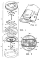
- Figure 1 is an exploded perspective view of a preferred embodiment of the theft-deterrent device of the present invention.
- Figure 2 illustrates the attachment of the theft-deterrent device of Figure 1 to a protected article or clothing.
- Figure 3 is a top plan view of a member of the one component of the theft-deterrent device of Figure 1 that contains the vials and the seal and anchors the pin.
- Figures 4A and 4B are sector sectional views of the detrimental-substance-containing component of the theft-deterrent device of Figure 1 taken along lines 4-4 in Figure 3, showing a sequence of operation as the breaker element of the pinhead moves to fracture the vials in response to the pin being forced downward.
- Figure 5 is a top plan view of the barrel of the second component of the theft-deterrent device of Figure 1.
- Figure 6 is a bottom plan view of the cover of the second component of the theft-deterrent device of Figure 1.
- a preferred embodiment of the theft-deterrent device of the present invention includes a first component 10 and a second component 12.
- the first component 10 includes a pin 14, and the second component 12 includes a clutch 16 for grasping the pin 14.
- the pin 14 is centrally located in the first component 10; and the clutch 16 is centrally located in the second component 12.
- the theft-deterrent device is attached to an article 18 to be protected (as illustrated in Figure 2) by passing the pin 14 through a portion of the protected article 18 and engaging the pin 14 in the clutch 16 so that the clutch 16 grasps the pin 14.
- the pin 14 has a head 40 that is anchored within the first component 10; and the clutch 16 in the second component 12 grasps the pin 14 to provide a predetermined retaining force, such as 100 pounds (25 newtons), for resisting separation of the components 10, 12 by prying or pulling the components apart.
- the predetermined retaining force must be much greater than the separation force that would be applied in attempting to separate the two components 10, 12 by using one's bare hands.
- the first component 10 includes a member 24 that contains two fragile elongated glass vials 20 that fracture when at least a predetermined pressure is applied thereto.
- Each vial 20 contains a detrimental substance 22 that would damage the protected article 18 if the vial were to be fractured while the theft-deterrent device was attached to the article 18.
- the detrimental substance 22 preferably is a fluid colored dye or permanent ink.
- the first component 10 includes a plastic vial-containing member 24 and a circular plastic cover 38.
- the member 24 is ultrasonically welded to the cover 38 at the circumferential edge of the member 24.
- the member 24 and the cover 38 define a head space 25 in which the pinhead 40 is anchored.
- the head space 25 also enables limited axial movement of the pinhead 40.
- the pin 14 passes through a hole 41 in an exposed surface 26 of the member 24.
- the exposed surface 26 of the member 24 further includes openings 31 into two chambers 27 defined by the member 24 for respectively disposing the two vials 20 adjacent such openings 31.
- the openings 31 are smaller than the vials 20 so as to recess the vials 20 from the exposed surface 26 and thereby prevent the vials 20 from being fractured during normal handling of the component 10.
- the pinhead 40 includes a breaker element 28 and a flange 29.
- the breaker element 28 exerts little or no pressure on the vials 20 while the attached pin 14 and clutch 16 are in a relaxed state, which occurs when no force is being applied to separate the two components 10, 12.
- the breaker element 28 has a wedge-shaped surface for applying more than the predetermined pressure against the vials 20 in response to the pinhead 40 being moved in response to application to the two components 10, 12 of at least a predetermined threshold separation force, such as approximately 40 pounds (10 newtons), that is nevertheless less than that required to overcome the predetermined retaining force, to thereby fracture the vials 20 and release the substance 22 contained therein before the components 10, 12 are separated by prying or pulling the components apart.
- a predetermined threshold separation force such as approximately 40 pounds (10 newtons)
- the predetermined threshold separation force must be well above both normal handling forces for the theft-deterrent device and the separation force that would be applied in attempting to separate the two components 10, 12 by using one's bare hands; and but yet, the predetermined threshold separation force must be easily attained by attempting to pry the two components 10, 12 apart with a screwdriver.
- the vials 20 are elongated with closed ends and are disposed in relation to the pinhead 40 such that the breaker element 28 can apply pressure to induce a high bending stress in the vials 20 and thereby completely fracture the vials 20.
- the surface of the breaker element 28 that applies the pressure against the vials 20 is made of a smooth, rigid material that does not scratch the vial 20.
- the vials 20 are made of glass; and the surface of the breaker element 28 that applies the pressure against the vial 20 is made of a fiber-loaded-reinforced thermoplastic material, such as glass-fiber-loaded nylon.
- the vials 20 are symmetrical]y disposed in relation to the pinhead 40 so that the pinhead 40 applies approximately equal pressure to both vials 20.
- a pliable seal 30 is disposed between the breaker element 28 and the vials 20.
- the seal 30 includes a hole 32 through which the pin 14 passes.
- the pliable seal 30 is disposed between the breaker element 28 and the vials 20 for preventing the detrimental substance 22 that is released from the fractured vials 20 from entering the head space 25 and for expelling the released detrimental substance 22 through the openings 31 in response to pressure applied against the seal 30 by the breaker element by said movement of the pinhead that results in the vial being fractured.
- the pliable seal 30 preferably is rubber, such as foam rubber or latex sheet material. The foam rubber flows has the advantage of flowing around the glass particles of the fractured vials 20.
- the seal 30 is more extensive than the breaker element 28; and the flange 29 of the pinhead 40 extends beyond the breaker element for contacting the seal 30 beyond the breaker element 28 for further forcing the seal 30 to expel the released detrimental substance 22 through the openings 31 in response to pressure applied against the seal 30 by the flange 29 by the movement of the pinhead 40 that results in the vials 20 being fractured.
- the seal 30 also serves as a shock absorbers for the vials 20 in order to prevent the vials 20 from being broken during normal handling of the component 10.
- the pin 14 When forced separation of the two components 10, 12 is attempted, the pin 14 is forced to move axially within the vial-containing member 24 and the breaker element 28 of the pinhead 40 applies pressure against the vials 20 to fracture the vials 20, as illustrated in Figures 4A and 4B.
- the pinhead 40 is shown in the relaxed position in Figure 4A and is shown in the position in which the vials 20 are fractured in response to downward movement of the pinhead 40 in Figure 4B.
- the second component 12 also is so structured as not to flex when an attempt is made to pry the first component 10 from the second component 12 while the two components are locked together, thereby concentrating separation forces resulting from said prying to be applied to forcing movement of the pinhead 40 within the member 24 of the first component 10.
- the second component 12 includes a plastic cover 58 and a plastic barrel 60.
- the barrel 60 includes a central chamber 62 that holds the housing of the clutch 16.
- the concealed surface 64 of the cover 12 includes a plurality of circular stiffening ribs 66; and the barrel 60 includes a plurality of supporting struts 68 extending radially between the central chamber 62 and the outer wall 70 of the barrel 60.
- the second component 12 also includes deflection plates 72 made of two-percent-carbon hardened spring steel, which line the central chamber 62 around the clutch 16 for deflecting the bit of a drill that one might use in an attempt to penetrate the housing of the clutch 16, and thereby shield the housing of the clutch 16 from a drilling tool.
- deflection plates 72 made of two-percent-carbon hardened spring steel, which line the central chamber 62 around the clutch 16 for deflecting the bit of a drill that one might use in an attempt to penetrate the housing of the clutch 16, and thereby shield the housing of the clutch 16 from a drilling tool.
- the barrel 60 is ultrasonically welded to the cover 58 at the circumferential edge of the cover 58 and at the upper edge of the central chamber 62.
Abstract
Description
- The present invention is generally directed to devices that may be attached to articles, such as merchandise, for deterring the theft of such articles, and is particularly directed to improvements in a theft-deterrent device of the type that contains a detrimental substance that damages a protected article attached to the device by releasing such substance when the device is tampered with during an unauthorized attempt to remove the device from the article.
- Typically, the device includes means for attaching the device to the article, with the attaching means being embodied in two components that are adapted to be locked together on opposite sides of a portion of said article to prevent unauthorized removal of the device from the article. A typical attaching means includes a pin having a head embodied in one of the two components and means embodied in the other component for receiving the free end of the pin. The device is attached to the protected article by passing the free end of the pin through a portion of the article. At least one of the two components includes a fragile elongated vial that fractures when flexed longitudinally, with said vial containing the detrimental substance that would damage the article if the vial were to be fractured while the device was attached to the article.
- Prior art devices of this nature are described in United States Patents Nos. 4,483,049 to Gustavsson et al., 4,670,950 to Wisecup et al. and 4,649,397 to Heaton et al. Typically, these devices are used to discourage the theft of such articles of merchandise as clothing, and the detrimental substance typically is an ink or dye or foul-smelling substance that permanently stains and or fouls the clothing so as to make the clothing unattractive and thereby generally unfit for wear.
- In both the device described in U.S. Patent No. 4,483,049 and the device described in U.S. Patent No. 4,670,950, a detrimental substance is contained in two frangible vials that are respectively disposed in two opposing components that are secured together on opposite sides of a portion of the protected article when the device is locked to the article.
- In the device described in U.S. Patent No. 4,483,049, the vials fracture when severely contacted by a tool, such as a screw driver, that typically would be used in an attempt to pry apart the opposing components of the device so that the device could be removed from the protected article. The vials are so disposed in the device as to be readily contacted by a tool being used to pry apart the object and thereby fracture to release the detrimental substance onto an protected article locked to the device.
- In the device described in U.S. Patent No. 4,670,950, the frangible vials are longitudinally disposed in the two opposing elongated components so that when either component is flexed longitudinally during an attempt to pry the two components apart, the vial contained therein fractures to release the detrimental substance onto an protected article locked to the device.
- In the device described in U.S. Patent No. 4,649,397, two frangible vials are longitudinally disposed in one of two opposing elongated components so that when such component is flexed longitudinally during an attempt to pry the two components apart, the vials contained therein fracture to release the detrimental substance onto an protected article locked to the device. Such device further contains an electronic article surveillance tag of the type described in U.S. Patent No. 4,481,428 to Lincoln H. Charlot,Jr.
- Another prior art detrimental-substance-containing theft-deterrent device having a vial that will fracture to release the detrimental substance whenever a forceful attempt is made to detach the theft-deterrent device from the article to be protected, is described in U.S. Patent No. 4,944,075 to Dennis L. Hogan. In such device, an attachment-pin-containing component having openings in a surface through which the pin passes for engagement with the other component includes a plurality of fragile elongated detrimental-substance-containing vials that fracture when at least a predetermined pressure is applied thereto; and defines a head space for enabling limited axial movement of the pinhead, and guide channels containing balls between the pinhead and the vials. The guide channels are contoured for enabling the pinhead to force the balls to move and apply more than said predetermined pressure against the vial in response to the pinhead being moved in response to application to the two components of at least a predetermined threshold separation force that is nevertheless less than that required to overcome the retaining force between the pin and the clutch, to thereby fracture at least one of the vials to release the substance contained therein through the openings and onto the article attached to the device before the components are separated by prying or pulling the components apart.
- The present invention provides an improvement to the detrimental-substance-containing component of the theft-deterrent device described in the aforementioned U.S. Patent No. 4,944,075 to Hogan that enhances expulsion of the detrimental substance from the detrimental-substance-containing component once any one of the vials is fractured.
- In one aspect, the present invention provides a detrimental-substance-containing component for use in a theft-deterrent device that includes means for attaching the device to the article, with said attaching means being embodied in two components that are adapted to be locked together on opposite sides of a portion of said article to prevent unauthorized removal of the device from the article, wherein the attaching means include a pin having a head that is anchored within the detrimental-substance-containing component and a clutch contained in the other component for grasping the pin to provide a predetermined retaining force for resisting separation of the components by prying or pulling the components apart, wherein the detrimental-substance-containing component includes a surface through which the pin passes for engagement with the other component, wherein said surface contains at least one opening; wherein the detrimental-substance-containing component includes at least one fragile vial that fractures when at least a predetermined pressure is applied thereto, with said vial being disposed adjacent said at least one opening and containing a detrimental substance that would damage an article attached to the device if the vial were to be fractured and the detrimental substance were to be released from the fractured vial through said at least one opening onto the attached article; wherein the detrimental-substance-containing component defines a head space for enabling limited axial movement of the pinhead; wherein the pinhead includes a breaker element having a contoured surface for applying more than said predetermined pressure against the vial in response to the pinhead being moved in response to application to the two components of at least a predetermined threshold separation force that is nevertheless less than that required to overcome said predetermined retaining force, to thereby fracture the vial and release the substance contained therein before the components are separated by prying or pulling the components apart; and wherein the detrimental-substance-containing component includes a pliable seal disposed between the breaker element and the vial for preventing the detrimental substance that is released from the fractured vial from entering the head space and for expelling the released detrimental substance through said at least one opening in response to pressure applied against the seal by the breaker element by said movement of the pinhead that results in the vial being fractured.
- Accordingly, the detrimental substance is expelled from the detrimental-substance-containing component and onto the article attached to the theft device even though the theft-deterrent device is oriented such that the detrimental-substance-containing component is positioned beneath the other component at the time when the vial is fractured; whereas except for the positive expulsion of the detrimental substance provided by the present invention, the force of gravity would retain the detrimental substance within the detrimental-substance-containing component.
- Expulsion of the detrimental substance is further improved in a preferred embodiment in which the seal is more extensive than the breaker element; and in which the pinhead further includes a flange extending beyond the breaker element for contacting the seal beyond the breaker element for further forcing the seal to expel the released detrimental substance through said at least one opening in response to pressure applied against the seal by the flange by said movement of the pinhead that results in the vial being fractured.
- In a second aspect, the present invention provides a detrimental-substance-containing component for use in a theft-deterrent device that includes means for attaching the device to the article, with said attaching means being embodied in two components that are adapted to be locked together on opposite sides of a portion of said article to prevent unauthorized removal of the device from the article, wherein the attaching means include a pin having a head that is anchored within the detrimental-substance-containing component and a clutch contained in the other component for grasping the pin to provide a predetermined retaining force for resisting separation of the components by prying or pulling the components apart, wherein the detrimental-substance-contatning component includes at least one fragile vial that fractures when at least a predetermined pressure is applied thereto, with said vial containing a detrimental substance that would damage an article attached to the device if the vial were to be fractured and the detrimental substance were to be released from the fractured vial onto the attached article; wherein the detrimental-substance-containing component defines a head space for enabling limited axial movement of the pinhead; wherein the pinhead includes a breaker element having a wedge-shaped surface for applying more than said predetermined pressure against the vial in response to the pinhead being moved in response to application to the two components of at least a predetermined threshold separation force that is nevertheless less than that required to overcome said predetermined retaining force, to thereby fracture the vial and release the substance contained therein before the components are separated by prying or pulling the components apart; and wherein the vial is elongated with closed ends and is disposed in relation to the pinhead such that the breaker element can apply pressure to induce a high bending stress in the vial and thereby completely fracture the vial.
- It has been found that if during the process of fracturing the vial, the breaker element induces a high bending stress in the vial without causing premature cracking. the vial will fracture completely; whereas if either the high bending stress is not induced or premature cracking occurs, the vial does not fracture completely. Such incomplete fracturing of the vial sometimes results in the fractured portions of the vial collapsing into the remaining portions of the vial in such a manner as to prevent a large portion of the detrimental substance from being expelled from the vial.
- Premature cracking of the vial may occur if the vial is scratched such that minute high pressure points occur when pressure is applied by the breaker element.
- To prevent scratching of the vial in those embodiments of the detrimental-substance-containing component of this second aspect of the present invention, as described above, in which the breaker element can contact the vial, the surface of the breaker element that applies the pressure against the vial is made of a smooth, rigid material that does not scratch the vial.
- In a preferred embodiment of this second aspect of the present invention, in which the vial is made of glass, the surface of the breaker element that applies the pressure against the vial is made of a fiber-loaded-reinforced thermoplastic material, such as glass-fiber-loaded nylon.
- Both of the aforementioned aspects of the invention are combined in the preferred embodiment of the present invention to still further enhance expulsion of the detrimental substance from the detrimental-substance-containing component.
- The present invention further provides theft-deterrent devices containing an improved detrimental-substance-containing component according to the present invention.
- Additional features of the present invention are described in relation to the description of the preferred embodiment.
- Figure 1 is an exploded perspective view of a preferred embodiment of the theft-deterrent device of the present invention.
- Figure 2 illustrates the attachment of the theft-deterrent device of Figure 1 to a protected article or clothing.
- Figure 3 is a top plan view of a member of the one component of the theft-deterrent device of Figure 1 that contains the vials and the seal and anchors the pin.
- Figures 4A and 4B are sector sectional views of the detrimental-substance-containing component of the theft-deterrent device of Figure 1 taken along lines 4-4 in Figure 3, showing a sequence of operation as the breaker element of the pinhead moves to fracture the vials in response to the pin being forced downward.
- Figure 5 is a top plan view of the barrel of the second component of the theft-deterrent device of Figure 1.
- Figure 6 is a bottom plan view of the cover of the second component of the theft-deterrent device of Figure 1.
- Referring to Figure 1, a preferred embodiment of the theft-deterrent device of the present invention includes a
first component 10 and asecond component 12. Thefirst component 10 includes apin 14, and thesecond component 12 includes aclutch 16 for grasping thepin 14. Thepin 14 is centrally located in thefirst component 10; and theclutch 16 is centrally located in thesecond component 12. The theft-deterrent device is attached to anarticle 18 to be protected (as illustrated in Figure 2) by passing thepin 14 through a portion of the protectedarticle 18 and engaging thepin 14 in theclutch 16 so that theclutch 16 grasps thepin 14. While thepin 16 is grasping thepin 14, thefirst component 10 and thesecond component 12 are locked together on opposite sides of a portion of the protectedarticle 18 and thereby prevent unauthorized removal of the theft-deterrent device from the protectedarticle 18. Thepin 14 has ahead 40 that is anchored within thefirst component 10; and theclutch 16 in thesecond component 12 grasps thepin 14 to provide a predetermined retaining force, such as 100 pounds (25 newtons), for resisting separation of thecomponents components - The
pin 14, theclutch 16 and the technique of releasing thepin 14 from the grasp of theclutch 16 so that thefirst component 10 can be unlocked from thesecond component 12 to thereby detach the protectedarticle 18 from the theft-deterrent device are described in U.S. Patent No. 4,523,356 to Lincoln H. Charlot, Jr. - Referring to Figures 1,3,4A and 4B, the
first component 10 includes amember 24 that contains two fragileelongated glass vials 20 that fracture when at least a predetermined pressure is applied thereto. Eachvial 20 contains adetrimental substance 22 that would damage the protectedarticle 18 if the vial were to be fractured while the theft-deterrent device was attached to thearticle 18. Thedetrimental substance 22 preferably is a fluid colored dye or permanent ink. - The
first component 10 includes a plastic vial-containingmember 24 and a circularplastic cover 38. Themember 24 is ultrasonically welded to thecover 38 at the circumferential edge of themember 24. - The
member 24 and thecover 38 define ahead space 25 in which thepinhead 40 is anchored. Thehead space 25 also enables limited axial movement of thepinhead 40. Thepin 14 passes through ahole 41 in an exposedsurface 26 of themember 24. - The exposed
surface 26 of themember 24 further includesopenings 31 into twochambers 27 defined by themember 24 for respectively disposing the twovials 20 adjacentsuch openings 31. Theopenings 31 are smaller than thevials 20 so as to recess thevials 20 from the exposedsurface 26 and thereby prevent thevials 20 from being fractured during normal handling of thecomponent 10. - The
pinhead 40 includes abreaker element 28 and aflange 29. - The
breaker element 28 exerts little or no pressure on thevials 20 while the attachedpin 14 and clutch 16 are in a relaxed state, which occurs when no force is being applied to separate the twocomponents - The
breaker element 28 has a wedge-shaped surface for applying more than the predetermined pressure against thevials 20 in response to thepinhead 40 being moved in response to application to the twocomponents vials 20 and release thesubstance 22 contained therein before thecomponents components components - The
vials 20 are elongated with closed ends and are disposed in relation to thepinhead 40 such that thebreaker element 28 can apply pressure to induce a high bending stress in thevials 20 and thereby completely fracture thevials 20. - The surface of the
breaker element 28 that applies the pressure against thevials 20 is made of a smooth, rigid material that does not scratch thevial 20. In the preferred embodiment, thevials 20 are made of glass; and the surface of thebreaker element 28 that applies the pressure against thevial 20 is made of a fiber-loaded-reinforced thermoplastic material, such as glass-fiber-loaded nylon. - The
vials 20 are symmetrical]y disposed in relation to thepinhead 40 so that thepinhead 40 applies approximately equal pressure to bothvials 20. - A
pliable seal 30 is disposed between thebreaker element 28 and thevials 20. Theseal 30 includes ahole 32 through which thepin 14 passes. Thepliable seal 30 is disposed between thebreaker element 28 and thevials 20 for preventing thedetrimental substance 22 that is released from the fracturedvials 20 from entering thehead space 25 and for expelling the releaseddetrimental substance 22 through theopenings 31 in response to pressure applied against theseal 30 by the breaker element by said movement of the pinhead that results in the vial being fractured. Thepliable seal 30 preferably is rubber, such as foam rubber or latex sheet material. The foam rubber flows has the advantage of flowing around the glass particles of the fracturedvials 20. - The
seal 30 is more extensive than thebreaker element 28; and theflange 29 of thepinhead 40 extends beyond the breaker element for contacting theseal 30 beyond thebreaker element 28 for further forcing theseal 30 to expel the releaseddetrimental substance 22 through theopenings 31 in response to pressure applied against theseal 30 by theflange 29 by the movement of thepinhead 40 that results in thevials 20 being fractured. - The
seal 30 also serves as a shock absorbers for thevials 20 in order to prevent thevials 20 from being broken during normal handling of thecomponent 10. - When forced separation of the two
components pin 14 is forced to move axially within the vial-containingmember 24 and thebreaker element 28 of thepinhead 40 applies pressure against thevials 20 to fracture thevials 20, as illustrated in Figures 4A and 4B. Thepinhead 40 is shown in the relaxed position in Figure 4A and is shown in the position in which thevials 20 are fractured in response to downward movement of thepinhead 40 in Figure 4B. - The
second component 12 also is so structured as not to flex when an attempt is made to pry thefirst component 10 from thesecond component 12 while the two components are locked together, thereby concentrating separation forces resulting from said prying to be applied to forcing movement of thepinhead 40 within themember 24 of thefirst component 10. - Referring to Figures 5 and 6, the
second component 12 includes aplastic cover 58 and aplastic barrel 60. Thebarrel 60 includes acentral chamber 62 that holds the housing of the clutch 16. In order to make thesecond component 12 rigid so that it does not flex, theconcealed surface 64 of thecover 12 includes a plurality ofcircular stiffening ribs 66; and thebarrel 60 includes a plurality of supportingstruts 68 extending radially between thecentral chamber 62 and theouter wall 70 of thebarrel 60. - The
second component 12 also includesdeflection plates 72 made of two-percent-carbon hardened spring steel, which line thecentral chamber 62 around the clutch 16 for deflecting the bit of a drill that one might use in an attempt to penetrate the housing of the clutch 16, and thereby shield the housing of the clutch 16 from a drilling tool. - The
barrel 60 is ultrasonically welded to thecover 58 at the circumferential edge of thecover 58 and at the upper edge of thecentral chamber 62.
Claims (9)
- A detrimental-substance-containing component (10) of a device for deterring theft of a protected article, the device comprising means for attaching the device to the article, with said attaching means being embodied in two components that are adapted to be locked together on opposite sides of a portion of said article to prevent unauthorized removal of the device from the article, wherein the attaching means include a pin (14) having a head (40) that is anchored within the detrimental-substance-containing component and a clutch contained in the other component for grasping the pin to provide a predetermined retaining force for resisting separation of the components by prying or pulling the components apart,
wherein the detrimental-substance-containing component includes a surface (26) through which the pin passes for engagement with the other component, wherein said surface contains at least one opening (31);
wherein the detrimental-substance-containing component includes at least one fragile vial (20) that fractures when at least a predetermined pressure is applied thereto, with said vial being disposed adjacent said at least one opening and containing a detrimental substance (22) that would damage an article attached to the device if the vial were to be fractured and the detrimental substance were to be released from the fractured vial through said at least one opening onto the attached article;
wherein the detrimental-substance-containing component defines a head space (25) for enabling limited axial movement of the pinhead;
wherein the pinhead includes a breaker element (28) having a contoured surface for applying more than said predetermined pressure against the vial in response to the pinhead being moved in response to application to the two components of at least a predetermined threshold separation force that is nevertheless less than that required to overcome said predetermined retaining force, to thereby fracture the vial and release the substance contained therein before the components are separated by prying or pulling the components apart; and
wherein the detrimental-substance-containing component includes a pliable seal (30) disposed between the breaker element and the vial for preventing the detrimental substance that is released from the fractured vial from entering the head space and for expelling the released detrimental substance through said at least one opening in response to pressure applied against the seal by the breaker element by said movement of the pinhead that results in the vial being fractured. - A component according to Claim 1, wherein the seal (30) is more extensive than the breaker element (28); and
therein the pinhead (40) further includes a flange (29) extending beyond the breaker element for contacting the seal beyond the breaker element for further forcing the seal to expel the released detrimental substance through said at least one opening in response to pressure applied against the seal by the flange by said movement of the pinhead that results in the vial being fractured. - A component according to Claim 1, wherein the contour of the breaker element (28) is wedge-shaped; and
wherein the vial (20) is elongated with closed ends and is disposed in relation to the pinhead (40) such that the breaker element can apply pressure to induce a high bending stress in the vial and thereby completely fracture the vial. - A detrimental-substance-containing component (10) of a device for deterring theft of a protected article, the device comprising means for attaching the device to the article, with said attaching means being embodied in two components that are adapted to be locked together on opposite sides of a portion of said article to prevent unauthorized removal of the device from the article, wherein the attaching means include a pin (14) having a head (40) that is anchored within the detrimental-substance-containing component and a clutch contained in the other component for grasping the pin to provide a predetermined retaining force for resisting separation of the components by prying or pulling the components apart,
wherein the detrimental-substance-containing component includes at least one fragile vial (20) that fractures when at least a predetermined pressure is applied thereto, with said vial containing a detrimental substance (22) that would damage an article attached to the device if the vial were to be fractured and the detrimental substance were to be released from the fractured vial onto the attached article;
wherein the detrimental-substance-containing component defines a head space (25) for enabling limited axial movement of the pinhead;
wherein the pinhead includes a breaker element (28) having a wedge-shaped surface for applying more than said predetermined pressure against the vial in response to the pinhead being moved in response to application to the two components of at least a predetermined threshold separation force that is nevertheless less than that required to overcome said predetermined retaining force, to thereby fracture the vial and release the substance contained therein before the components are separated by prying or pulling the components apart; and
wherein the vial is elongated with closed ends and is disposed in relation to the pinhead such that the breaker element can apply pressure to induce a high bending stress in the vial and thereby completely fracture the vial. - A component according to Claim 1 or 4, wherein the surface of the breaker element (28) that applies said pressure against the vial is made of a smooth, rigid material that does not scratch the vial.
- A component according to Claim 1 or 4, wherein the vial (20) is made of glass; and
wherein the surface of the breaker element (28) that applies said pressure against the vial is made of a smooth, rigid fiber-loaded-reinforced thermoplastic material that does not scratch glass. - A component according to Claim 1 or 4, comprising a plurality of said vials (20) symmetrically disposed in relation to the breaker element (28) of the pinhead (40).
- A device for deterring theft of a protected article, comprising
means for attaching the device to the article, with said attaching means being embodied in two components (10,12) that are adapted to be locked together on opposite sides of a portion of said article to prevent unauthorized removal of the device from the article, wherein the attaching means include a pin (14) having a head (40) that is anchored within one component (10) and a clutch (16) contained in the other component (12) for grasping the pin to provide a predetermined retaining force for resisting separation of the components by prying or pulling the components apart;
wherein said one component (10) includes a surface (26) through which the pin passes for engagement with the other component (12), wherein said surface contains at least one opening (31);
wherein said one component (10) includes at least one fragile vial (20) that fractures when at least a predetermined pressure is applied thereto, with said vial being disposed adjacent said at least one opening and containing a detrimental substance (22) that would damage an article attached to the device if the vial were to be fractured and the detrimental substance were to be released from the fractured vial through said at least one opening onto the attached article;
wherein said one component (10) defines a head space (25) for enabling limited axial movement of the pinhead;
wherein the pinhead includes a breaker element (28) having a contoured surface for applying more than said predetermined pressure against the vial in response to the pinhead being moved in response to application to the two components of at least a predetermined threshold separation force that is nevertheless less than that required to overcome said predetermined retaining force, to thereby fracture the vial and release the substance contained therein before the components are separated by prying or pulling the components apart; and
wherein the one component (10) further includes a pliable seal (30) disposed between the breaker element and the vial for preventing the detrimental substance that is released from the fractured vial from entering the head space and for expelling the released detrimental substance through said at least one opening in response to pressure applied against the seal by the breaker element by said movement of the pinhead that results in the vial being fractured. - A device for deterring theft of a protected article, comprising
means for attaching the device to the article, with said attaching means being embodied in two components (10,12) that are adapted to be locked together on opposite sides of a portion of said article to prevent unauthorized removal of the device from the article, wherein the attaching means include a pin (14) having a head (40) that is anchored within one component (10) and a clutch (16) contained in the other component (12) for grasping the pin to provide a predetermined retaining force for resisting separation of the components by prying or pulling the components apart;
wherein said one component (10) includes at least one fragile vial (20) that fractures when at least a predetermined pressure is applied thereto, with said vial containing a detrimental substance (22) that would damage an article attached to the device if the vial were to be fractured and the detrimental substance were to be released from the fractured vial onto the attached article;
wherein said one component (10) defines a head space (25) for enabling limited axial movement of the pinhead;
wherein the pinhead includes a breaker element (28) having a wedge-shaped surface for applying more than said predeterred pressure against the vial in response to the pinhead being moved in response to application to the two components of at least a predetermined threshold separation force that is nevertheless less than that required to overcome said predetermined retaining force, to thereby fracture the vial and release the substance contained therein before the components are separated by prying or pulling the components apart; and
wherein the vial is elongated with closed ends and is disposed in relation to the pinhead such that the breaker element can apply pressure to induce a high bending stress in the vial and thereby completely fracture the vial.
Applications Claiming Priority (2)
| Application Number | Priority Date | Filing Date | Title |
|---|---|---|---|
| US602818 | 1990-10-24 | ||
| US07/602,818 US5054172A (en) | 1990-10-24 | 1990-10-24 | Expulsion of detrimental substance from theft-deterrent device |
Publications (2)
| Publication Number | Publication Date |
|---|---|
| EP0482800A1 true EP0482800A1 (en) | 1992-04-29 |
| EP0482800B1 EP0482800B1 (en) | 1996-04-10 |
Family
ID=24412920
Family Applications (1)
| Application Number | Title | Priority Date | Filing Date |
|---|---|---|---|
| EP91309324A Expired - Lifetime EP0482800B1 (en) | 1990-10-24 | 1991-10-10 | Expulsion of detrimental substance from theft-deterrent device |
Country Status (9)
| Country | Link |
|---|---|
| US (2) | US5054172A (en) |
| EP (1) | EP0482800B1 (en) |
| JP (1) | JP3224571B2 (en) |
| AT (1) | ATE136618T1 (en) |
| AU (1) | AU644227B2 (en) |
| CA (1) | CA2052980C (en) |
| DE (1) | DE69118648T2 (en) |
| ES (1) | ES2085436T3 (en) |
| NO (1) | NO914124L (en) |
Cited By (2)
| Publication number | Priority date | Publication date | Assignee | Title |
|---|---|---|---|---|
| EP0585770A1 (en) * | 1992-09-01 | 1994-03-09 | Färgklämman Svenska Ab | A theft-deterrent device for theft-attractive articles |
| WO1994009235A1 (en) * | 1992-10-22 | 1994-04-28 | Hendrikx, Jacobus, Gerardus, Maria | Anti-theft system |
Families Citing this family (39)
| Publication number | Priority date | Publication date | Assignee | Title |
|---|---|---|---|---|
| SE467556B (en) * | 1990-09-03 | 1992-08-03 | Faergklaemman Svenska Ab | STOELDSKYDDSANORDNING |
| DE9111503U1 (en) * | 1991-09-16 | 1991-12-19 | Antonson Security Denmark A/S, Karlslunde, Dk | |
| US5140836A (en) * | 1991-09-19 | 1992-08-25 | Security Tag Systems, Inc. | Theft-deterrent device including clamp |
| US5309740A (en) * | 1992-04-13 | 1994-05-10 | Sensormatic Electronics Corporation | Ink tack |
| US5205024A (en) * | 1992-08-31 | 1993-04-27 | Sensormatic Electronics Corporation | Ink tack with enhanced vial protection |
| US5347262A (en) * | 1992-10-23 | 1994-09-13 | Security Tag Systems, Inc. | Theft-deterrent device providing force-sensitive tamper detection |
| US5337459A (en) * | 1993-03-16 | 1994-08-16 | Security Tag Systems, Inc. | Magnetically releasable clamp |
| US5428875A (en) * | 1993-11-16 | 1995-07-04 | Sensormatic Electronics Corporation | Theft deterrent tag with a cutting blade |
| SE9401604L (en) * | 1994-05-09 | 1995-11-10 | Faergklaemman Svenska Ab | Anti-theft device intended to be attached to goods that require theft |
| US5587703A (en) * | 1994-10-25 | 1996-12-24 | Dumont; Charles | Universal merchandise tag |
| SE515559C2 (en) * | 1996-06-27 | 2001-08-27 | Faergklaemman Ab | Ampoule and anti-theft device with ampoule |
| US5680681A (en) * | 1996-08-26 | 1997-10-28 | Fuss; Arthur | Theft deterrent garment tag with ink identification |
| WO1998024075A1 (en) * | 1996-11-27 | 1998-06-04 | Dumont Charles J | Universal merchandise tag |
| US5852856A (en) * | 1997-11-13 | 1998-12-29 | Seidel; Stuart T. | Anti theft ink tag |
| EP0918125B1 (en) * | 1997-11-21 | 2002-06-26 | Cross Point B.V. | Theft deterrent device |
| US6255950B1 (en) | 1999-10-19 | 2001-07-03 | Sensormatic Electronics Corporation | Tack assembly for electronic article surveillance tags |
| US6449991B1 (en) | 2000-04-12 | 2002-09-17 | Sensormatic Electronics Corporation | One part theft deterrent device |
| AU2002225925A1 (en) | 2000-10-26 | 2002-05-06 | Alpha Security Products, Inc. | Eas tag holder |
| US6722166B2 (en) * | 2002-07-29 | 2004-04-20 | Johan Skjellerup | Security tag assembly |
| US20040066299A1 (en) * | 2002-10-02 | 2004-04-08 | Hanabusa Russell Minoru | Attack deterrent and attacker identification system |
| US7194879B2 (en) * | 2003-02-21 | 2007-03-27 | Alpha Security Products, Inc. | Security container with linked primary and secondary security features |
| US7382256B2 (en) * | 2004-12-09 | 2008-06-03 | Johan Skjellerup | Security system for preventing unauthorized removal of merchandise |
| US20060139176A1 (en) * | 2004-12-09 | 2006-06-29 | Johan Skjellerup | Security tag assembly |
| US7286054B2 (en) * | 2004-12-09 | 2007-10-23 | Johan Skjellerup | Security system for preventing unauthorized removal of merchandise |
| US8242910B2 (en) * | 2004-12-09 | 2012-08-14 | Johan Skjellerup | Security system for preventing unauthorized removal of merchandise |
| US7474216B2 (en) * | 2004-12-09 | 2009-01-06 | Johan Skjellerup | Security system for preventing unauthorized removal of merchandise |
| US8223022B2 (en) * | 2004-12-09 | 2012-07-17 | Johan Skjellerup | Security tag assembly |
| US7817041B2 (en) * | 2004-12-09 | 2010-10-19 | Johan Skjellerup | Security system for preventing unauthorized removal of merchandise |
| US7633396B2 (en) | 2006-02-07 | 2009-12-15 | Sensormatic Electronics, LLC | Electronic article surveillance tag having an expulsion detrimental substance system with substance routing system |
| SE531331C2 (en) * | 2007-06-15 | 2009-02-24 | Faergklaemman Ab | Anti-theft elements intended to be attached to a product |
| US8704665B2 (en) * | 2009-06-15 | 2014-04-22 | Wg Security Products | Multiple technology EAS tag and system |
| US9091100B2 (en) | 2009-06-15 | 2015-07-28 | Wg Security Products | EAS tag with benefit denial features |
| FR2947086B1 (en) * | 2009-06-18 | 2012-05-11 | Exaqtworld | DEVICE FOR MARKING AN ARTICLE FOR IDENTIFICATION |
| US20110113437A1 (en) * | 2009-11-10 | 2011-05-12 | Sensormatic Electronics Corporation | Method and system for media disc loss prevention |
| US8590348B1 (en) | 2011-10-31 | 2013-11-26 | Braebum Asset Holdings, LLC. | Security tag assembly |
| US8590349B2 (en) | 2012-03-20 | 2013-11-26 | Braebum Asset Holdings, LLC. | Security tag assembly |
| FR3007783B1 (en) * | 2013-06-28 | 2015-07-10 | Fors France | ANTI-THEFT DEVICE FOR ATTACHING TO AN ARTICLE FOR FREE SALE |
| US10096217B2 (en) | 2016-05-11 | 2018-10-09 | Braeburn Asset Holdings, Llc | Security system and security tag assembly |
| US10480219B2 (en) | 2017-03-20 | 2019-11-19 | All-Tag Corporation | Method and apparatus for upgrading ink stain antitheft tags with RFID communications function |
Citations (1)
| Publication number | Priority date | Publication date | Assignee | Title |
|---|---|---|---|---|
| US4944075A (en) * | 1989-09-18 | 1990-07-31 | Security Tag Systems, Inc. | Detrimental-substance-containing theft-deterrent device |
Family Cites Families (6)
| Publication number | Priority date | Publication date | Assignee | Title |
|---|---|---|---|---|
| US2804029A (en) * | 1955-06-09 | 1957-08-27 | John P Fitzgerald | Safe protector |
| SE423938B (en) * | 1980-04-11 | 1982-06-14 | Bo Ollie Gustavsson | STOLDSKYDDSELEMENT |
| US4590461A (en) * | 1984-10-05 | 1986-05-20 | Knogo Corporation | Tamper resistant target wafer and fastener assembly |
| US4649397A (en) * | 1985-04-08 | 1987-03-10 | Monarch Marking Systems, Inc. | Theft deterrent tag |
| US4670950A (en) * | 1985-05-13 | 1987-06-09 | Monarch Marking Systems, Inc. | Theft-deterrent tag |
| SE467556B (en) * | 1990-09-03 | 1992-08-03 | Faergklaemman Svenska Ab | STOELDSKYDDSANORDNING |
-
1990
- 1990-10-24 US US07/602,818 patent/US5054172A/en not_active Ceased
-
1991
- 1991-10-08 CA CA 2052980 patent/CA2052980C/en not_active Expired - Lifetime
- 1991-10-10 AT AT91309324T patent/ATE136618T1/en not_active IP Right Cessation
- 1991-10-10 ES ES91309324T patent/ES2085436T3/en not_active Expired - Lifetime
- 1991-10-10 DE DE1991618648 patent/DE69118648T2/en not_active Expired - Lifetime
- 1991-10-10 EP EP91309324A patent/EP0482800B1/en not_active Expired - Lifetime
- 1991-10-18 AU AU85941/91A patent/AU644227B2/en not_active Expired
- 1991-10-21 NO NO91914124A patent/NO914124L/en unknown
- 1991-10-23 JP JP30269691A patent/JP3224571B2/en not_active Expired - Fee Related
-
1992
- 1992-09-30 US US07/954,905 patent/USRE35361E/en not_active Expired - Lifetime
Patent Citations (1)
| Publication number | Priority date | Publication date | Assignee | Title |
|---|---|---|---|---|
| US4944075A (en) * | 1989-09-18 | 1990-07-31 | Security Tag Systems, Inc. | Detrimental-substance-containing theft-deterrent device |
Cited By (3)
| Publication number | Priority date | Publication date | Assignee | Title |
|---|---|---|---|---|
| EP0585770A1 (en) * | 1992-09-01 | 1994-03-09 | Färgklämman Svenska Ab | A theft-deterrent device for theft-attractive articles |
| US5392620A (en) * | 1992-09-01 | 1995-02-28 | Fargklamman Svenska Ab | Theft-deterrent device for use with theft-attractive articles |
| WO1994009235A1 (en) * | 1992-10-22 | 1994-04-28 | Hendrikx, Jacobus, Gerardus, Maria | Anti-theft system |
Also Published As
| Publication number | Publication date |
|---|---|
| CA2052980C (en) | 2001-08-21 |
| NO914124D0 (en) | 1991-10-21 |
| CA2052980A1 (en) | 1992-04-25 |
| EP0482800B1 (en) | 1996-04-10 |
| AU644227B2 (en) | 1993-12-02 |
| DE69118648T2 (en) | 1996-08-29 |
| JP3224571B2 (en) | 2001-10-29 |
| NO914124L (en) | 1992-04-27 |
| AU8594191A (en) | 1992-04-30 |
| ATE136618T1 (en) | 1996-04-15 |
| ES2085436T3 (en) | 1996-06-01 |
| USRE35361E (en) | 1996-10-29 |
| DE69118648D1 (en) | 1996-05-15 |
| JPH04264999A (en) | 1992-09-21 |
| US5054172A (en) | 1991-10-08 |
Similar Documents
| Publication | Publication Date | Title |
|---|---|---|
| US5054172A (en) | Expulsion of detrimental substance from theft-deterrent device | |
| EP0419086B1 (en) | Detrimental-substance-containing theft-deterrent device | |
| US5031287A (en) | Detrimental-substance-containing theft-deterrent device | |
| US4670950A (en) | Theft-deterrent tag | |
| US5957313A (en) | Theft preventing device, particularly for bottles | |
| US4802700A (en) | Locking seal | |
| EP0463727B1 (en) | Pin-clutch mechanism for theft deterrent device | |
| US4590461A (en) | Tamper resistant target wafer and fastener assembly | |
| US4531264A (en) | Theft detection system target fastener | |
| US5205024A (en) | Ink tack with enhanced vial protection | |
| US4156302A (en) | Monitor actuating assembly and reusable fastener device therefor | |
| US5852856A (en) | Anti theft ink tag | |
| US5309740A (en) | Ink tack | |
| CN203113966U (en) | Safe label |
Legal Events
| Date | Code | Title | Description |
|---|---|---|---|
| PUAI | Public reference made under article 153(3) epc to a published international application that has entered the european phase |
Free format text: ORIGINAL CODE: 0009012 |
|
| AK | Designated contracting states |
Kind code of ref document: A1 Designated state(s): AT BE CH DE DK ES FR GB IT LI NL SE |
|
| 17P | Request for examination filed |
Effective date: 19921009 |
|
| 17Q | First examination report despatched |
Effective date: 19930805 |
|
| RAP1 | Party data changed (applicant data changed or rights of an application transferred) |
Owner name: SECURITY TAG SYSTEMS, INC. |
|
| GRAH | Despatch of communication of intention to grant a patent |
Free format text: ORIGINAL CODE: EPIDOS IGRA |
|
| GRAA | (expected) grant |
Free format text: ORIGINAL CODE: 0009210 |
|
| AK | Designated contracting states |
Kind code of ref document: B1 Designated state(s): AT BE CH DE DK ES FR GB IT LI NL SE |
|
| PG25 | Lapsed in a contracting state [announced via postgrant information from national office to epo] |
Ref country code: IT Free format text: LAPSE BECAUSE OF FAILURE TO SUBMIT A TRANSLATION OF THE DESCRIPTION OR TO PAY THE FEE WITHIN THE PRE;WARNING: LAPSES OF ITALIAN PATENTS WITH EFFECTIVE DATE BEFORE 2007 MAY HAVE OCCURRED AT ANY TIME BEFORE 2007. THE CORRECT EFFECTIVE DATE MAY BE DIFFERENT FROM THE ONE RECORDED.SCRIBED TIME-LIMIT Effective date: 19960410 Ref country code: AT Effective date: 19960410 Ref country code: NL Free format text: LAPSE BECAUSE OF FAILURE TO SUBMIT A TRANSLATION OF THE DESCRIPTION OR TO PAY THE FEE WITHIN THE PRESCRIBED TIME-LIMIT Effective date: 19960410 Ref country code: BE Effective date: 19960410 Ref country code: DK Effective date: 19960410 Ref country code: LI Effective date: 19960410 Ref country code: CH Effective date: 19960410 |
|
| REF | Corresponds to: |
Ref document number: 136618 Country of ref document: AT Date of ref document: 19960415 Kind code of ref document: T |
|
| ET | Fr: translation filed | ||
| REF | Corresponds to: |
Ref document number: 69118648 Country of ref document: DE Date of ref document: 19960515 |
|
| REG | Reference to a national code |
Ref country code: ES Ref legal event code: FG2A Ref document number: 2085436 Country of ref document: ES Kind code of ref document: T3 |
|
| NLV1 | Nl: lapsed or annulled due to failure to fulfill the requirements of art. 29p and 29m of the patents act | ||
| REG | Reference to a national code |
Ref country code: CH Ref legal event code: PL |
|
| PLBE | No opposition filed within time limit |
Free format text: ORIGINAL CODE: 0009261 |
|
| STAA | Information on the status of an ep patent application or granted ep patent |
Free format text: STATUS: NO OPPOSITION FILED WITHIN TIME LIMIT |
|
| 26N | No opposition filed | ||
| REG | Reference to a national code |
Ref country code: GB Ref legal event code: 732E |
|
| REG | Reference to a national code |
Ref country code: FR Ref legal event code: TP |
|
| REG | Reference to a national code |
Ref country code: GB Ref legal event code: IF02 |
|
| REG | Reference to a national code |
Ref country code: FR Ref legal event code: TP Ref country code: FR Ref legal event code: CJ Ref country code: FR Ref legal event code: CD |
|
| PGFP | Annual fee paid to national office [announced via postgrant information from national office to epo] |
Ref country code: FR Payment date: 20101105 Year of fee payment: 20 |
|
| PGFP | Annual fee paid to national office [announced via postgrant information from national office to epo] |
Ref country code: DE Payment date: 20101027 Year of fee payment: 20 |
|
| PGFP | Annual fee paid to national office [announced via postgrant information from national office to epo] |
Ref country code: GB Payment date: 20101025 Year of fee payment: 20 Ref country code: SE Payment date: 20101027 Year of fee payment: 20 |
|
| PGFP | Annual fee paid to national office [announced via postgrant information from national office to epo] |
Ref country code: ES Payment date: 20101026 Year of fee payment: 20 |
|
| REG | Reference to a national code |
Ref country code: DE Ref legal event code: R071 Ref document number: 69118648 Country of ref document: DE |
|
| REG | Reference to a national code |
Ref country code: DE Ref legal event code: R071 Ref document number: 69118648 Country of ref document: DE |
|
| REG | Reference to a national code |
Ref country code: GB Ref legal event code: PE20 Expiry date: 20111009 |
|
| REG | Reference to a national code |
Ref country code: SE Ref legal event code: EUG |
|
| PG25 | Lapsed in a contracting state [announced via postgrant information from national office to epo] |
Ref country code: GB Free format text: LAPSE BECAUSE OF EXPIRATION OF PROTECTION Effective date: 20111009 |
|
| PG25 | Lapsed in a contracting state [announced via postgrant information from national office to epo] |
Ref country code: DE Free format text: LAPSE BECAUSE OF EXPIRATION OF PROTECTION Effective date: 20111011 |
|
| REG | Reference to a national code |
Ref country code: ES Ref legal event code: FD2A Effective date: 20130725 |
|
| PG25 | Lapsed in a contracting state [announced via postgrant information from national office to epo] |
Ref country code: ES Free format text: LAPSE BECAUSE OF EXPIRATION OF PROTECTION Effective date: 20111011 |