EP0482776A1 - Token for use in pull-tab ring openers of containers - Google Patents
Token for use in pull-tab ring openers of containers Download PDFInfo
- Publication number
- EP0482776A1 EP0482776A1 EP91308977A EP91308977A EP0482776A1 EP 0482776 A1 EP0482776 A1 EP 0482776A1 EP 91308977 A EP91308977 A EP 91308977A EP 91308977 A EP91308977 A EP 91308977A EP 0482776 A1 EP0482776 A1 EP 0482776A1
- Authority
- EP
- European Patent Office
- Prior art keywords
- token
- strip
- lever
- pull
- ring
- Prior art date
- Legal status (The legal status is an assumption and is not a legal conclusion. Google has not performed a legal analysis and makes no representation as to the accuracy of the status listed.)
- Granted
Links
Images


Classifications
-
- B—PERFORMING OPERATIONS; TRANSPORTING
- B65—CONVEYING; PACKING; STORING; HANDLING THIN OR FILAMENTARY MATERIAL
- B65D—CONTAINERS FOR STORAGE OR TRANSPORT OF ARTICLES OR MATERIALS, e.g. BAGS, BARRELS, BOTTLES, BOXES, CANS, CARTONS, CRATES, DRUMS, JARS, TANKS, HOPPERS, FORWARDING CONTAINERS; ACCESSORIES, CLOSURES, OR FITTINGS THEREFOR; PACKAGING ELEMENTS; PACKAGES
- B65D77/00—Packages formed by enclosing articles or materials in preformed containers, e.g. boxes, cartons, sacks or bags
- B65D77/22—Details
- B65D77/24—Inserts or accessories added or incorporated during filling of containers
-
- B—PERFORMING OPERATIONS; TRANSPORTING
- B65—CONVEYING; PACKING; STORING; HANDLING THIN OR FILAMENTARY MATERIAL
- B65D—CONTAINERS FOR STORAGE OR TRANSPORT OF ARTICLES OR MATERIALS, e.g. BAGS, BARRELS, BOTTLES, BOXES, CANS, CARTONS, CRATES, DRUMS, JARS, TANKS, HOPPERS, FORWARDING CONTAINERS; ACCESSORIES, CLOSURES, OR FITTINGS THEREFOR; PACKAGING ELEMENTS; PACKAGES
- B65D17/00—Rigid or semi-rigid containers specially constructed to be opened by cutting or piercing, or by tearing of frangible members or portions
- B65D17/28—Rigid or semi-rigid containers specially constructed to be opened by cutting or piercing, or by tearing of frangible members or portions at lines or points of weakness
- B65D17/401—Rigid or semi-rigid containers specially constructed to be opened by cutting or piercing, or by tearing of frangible members or portions at lines or points of weakness characterised by having the line of weakness provided in an end wall
- B65D17/4012—Rigid or semi-rigid containers specially constructed to be opened by cutting or piercing, or by tearing of frangible members or portions at lines or points of weakness characterised by having the line of weakness provided in an end wall for opening partially by means of a tearing tab
-
- G—PHYSICS
- G09—EDUCATION; CRYPTOGRAPHY; DISPLAY; ADVERTISING; SEALS
- G09F—DISPLAYING; ADVERTISING; SIGNS; LABELS OR NAME-PLATES; SEALS
- G09F23/00—Advertising on or in specific articles, e.g. ashtrays, letter-boxes
- G09F23/02—Advertising on or in specific articles, e.g. ashtrays, letter-boxes the advertising matter being displayed by the operation of the article
-
- B—PERFORMING OPERATIONS; TRANSPORTING
- B65—CONVEYING; PACKING; STORING; HANDLING THIN OR FILAMENTARY MATERIAL
- B65D—CONTAINERS FOR STORAGE OR TRANSPORT OF ARTICLES OR MATERIALS, e.g. BAGS, BARRELS, BOTTLES, BOXES, CANS, CARTONS, CRATES, DRUMS, JARS, TANKS, HOPPERS, FORWARDING CONTAINERS; ACCESSORIES, CLOSURES, OR FITTINGS THEREFOR; PACKAGING ELEMENTS; PACKAGES
- B65D2517/00—Containers specially constructed to be opened by cutting, piercing or tearing of wall portions, e.g. preserving cans or tins
- B65D2517/0001—Details
- B65D2517/001—Action for opening container
- B65D2517/0014—Action for opening container pivot tab and push-down tear panel
-
- B—PERFORMING OPERATIONS; TRANSPORTING
- B65—CONVEYING; PACKING; STORING; HANDLING THIN OR FILAMENTARY MATERIAL
- B65D—CONTAINERS FOR STORAGE OR TRANSPORT OF ARTICLES OR MATERIALS, e.g. BAGS, BARRELS, BOTTLES, BOXES, CANS, CARTONS, CRATES, DRUMS, JARS, TANKS, HOPPERS, FORWARDING CONTAINERS; ACCESSORIES, CLOSURES, OR FITTINGS THEREFOR; PACKAGING ELEMENTS; PACKAGES
- B65D2517/00—Containers specially constructed to be opened by cutting, piercing or tearing of wall portions, e.g. preserving cans or tins
- B65D2517/0001—Details
- B65D2517/0047—Provided with additional elements other than for closing the opening
- B65D2517/0052—Prizes, tokens, badges or other information carrying devices
- B65D2517/0053—Prizes, tokens, badges or other information carrying devices forming part of, or connected to, the tab
-
- B—PERFORMING OPERATIONS; TRANSPORTING
- B65—CONVEYING; PACKING; STORING; HANDLING THIN OR FILAMENTARY MATERIAL
- B65D—CONTAINERS FOR STORAGE OR TRANSPORT OF ARTICLES OR MATERIALS, e.g. BAGS, BARRELS, BOTTLES, BOXES, CANS, CARTONS, CRATES, DRUMS, JARS, TANKS, HOPPERS, FORWARDING CONTAINERS; ACCESSORIES, CLOSURES, OR FITTINGS THEREFOR; PACKAGING ELEMENTS; PACKAGES
- B65D2517/00—Containers specially constructed to be opened by cutting, piercing or tearing of wall portions, e.g. preserving cans or tins
- B65D2517/0001—Details
- B65D2517/0058—Other details of container end panel
- B65D2517/0059—General cross-sectional shape of container end panel
- B65D2517/0061—U-shaped
- B65D2517/0062—U-shaped and provided with an additional U-shaped peripheral channel
-
- Y—GENERAL TAGGING OF NEW TECHNOLOGICAL DEVELOPMENTS; GENERAL TAGGING OF CROSS-SECTIONAL TECHNOLOGIES SPANNING OVER SEVERAL SECTIONS OF THE IPC; TECHNICAL SUBJECTS COVERED BY FORMER USPC CROSS-REFERENCE ART COLLECTIONS [XRACs] AND DIGESTS
- Y10—TECHNICAL SUBJECTS COVERED BY FORMER USPC
- Y10T—TECHNICAL SUBJECTS COVERED BY FORMER US CLASSIFICATION
- Y10T29/00—Metal working
- Y10T29/49—Method of mechanical manufacture
- Y10T29/49826—Assembling or joining
- Y10T29/49863—Assembling or joining with prestressing of part
- Y10T29/4987—Elastic joining of parts
- Y10T29/49872—Confining elastic part in socket
-
- Y—GENERAL TAGGING OF NEW TECHNOLOGICAL DEVELOPMENTS; GENERAL TAGGING OF CROSS-SECTIONAL TECHNOLOGIES SPANNING OVER SEVERAL SECTIONS OF THE IPC; TECHNICAL SUBJECTS COVERED BY FORMER USPC CROSS-REFERENCE ART COLLECTIONS [XRACs] AND DIGESTS
- Y10—TECHNICAL SUBJECTS COVERED BY FORMER USPC
- Y10T—TECHNICAL SUBJECTS COVERED BY FORMER US CLASSIFICATION
- Y10T29/00—Metal working
- Y10T29/49—Method of mechanical manufacture
- Y10T29/49826—Assembling or joining
- Y10T29/49908—Joining by deforming
- Y10T29/49936—Surface interlocking
-
- Y—GENERAL TAGGING OF NEW TECHNOLOGICAL DEVELOPMENTS; GENERAL TAGGING OF CROSS-SECTIONAL TECHNOLOGIES SPANNING OVER SEVERAL SECTIONS OF THE IPC; TECHNICAL SUBJECTS COVERED BY FORMER USPC CROSS-REFERENCE ART COLLECTIONS [XRACs] AND DIGESTS
- Y10—TECHNICAL SUBJECTS COVERED BY FORMER USPC
- Y10T—TECHNICAL SUBJECTS COVERED BY FORMER US CLASSIFICATION
- Y10T29/00—Metal working
- Y10T29/51—Plural diverse manufacturing apparatus including means for metal shaping or assembling
- Y10T29/5136—Separate tool stations for selective or successive operation on work
- Y10T29/5137—Separate tool stations for selective or successive operation on work including assembling or disassembling station
- Y10T29/5142—Separate tool stations for selective or successive operation on work including assembling or disassembling station and means to sever work from supply
-
- Y—GENERAL TAGGING OF NEW TECHNOLOGICAL DEVELOPMENTS; GENERAL TAGGING OF CROSS-SECTIONAL TECHNOLOGIES SPANNING OVER SEVERAL SECTIONS OF THE IPC; TECHNICAL SUBJECTS COVERED BY FORMER USPC CROSS-REFERENCE ART COLLECTIONS [XRACs] AND DIGESTS
- Y10—TECHNICAL SUBJECTS COVERED BY FORMER USPC
- Y10T—TECHNICAL SUBJECTS COVERED BY FORMER US CLASSIFICATION
- Y10T29/00—Metal working
- Y10T29/53—Means to assemble or disassemble
- Y10T29/53313—Means to interrelatedly feed plural work parts from plural sources without manual intervention
- Y10T29/53383—Means to interrelatedly feed plural work parts from plural sources without manual intervention and means to fasten work parts together
- Y10T29/53387—Means to interrelatedly feed plural work parts from plural sources without manual intervention and means to fasten work parts together by deforming
-
- Y—GENERAL TAGGING OF NEW TECHNOLOGICAL DEVELOPMENTS; GENERAL TAGGING OF CROSS-SECTIONAL TECHNOLOGIES SPANNING OVER SEVERAL SECTIONS OF THE IPC; TECHNICAL SUBJECTS COVERED BY FORMER USPC CROSS-REFERENCE ART COLLECTIONS [XRACs] AND DIGESTS
- Y10—TECHNICAL SUBJECTS COVERED BY FORMER USPC
- Y10T—TECHNICAL SUBJECTS COVERED BY FORMER US CLASSIFICATION
- Y10T29/00—Metal working
- Y10T29/53—Means to assemble or disassemble
- Y10T29/534—Multiple station assembly or disassembly apparatus
- Y10T29/53417—Means to fasten work parts together
- Y10T29/53422—Means to fasten work parts together by deforming
Definitions
- This invention relates to tokens, attached to an article of packaging, which may be used as proof of purchase of the article or for other purpose. More particularly, but not exclusively, the invention relates to a proof of purchase token attached to the lever used to open cans commonly used to contain beverages or other products, a method of fixing a token to a pull ring, and apparatus for carrying out the method.
- Pull ring can ends having a printed underside for gaming purposes were used in America until legislation in certain States banned the use of completely detachable ring pulls because the torn edge were perceived to be dangerous litter.
- United States Patent 4459910 Metal Box Can/Taube
- An embossing press used to incise numbers on the underside of the ring pull of a beverage can end, the intention being that certain numbers would qualify the purchaser to claim a prize.
- British Patent 1540229 (Reynolds Metals Co/Cudzik) describes a can end for beverage cans in which a lever attached to the can end at a hinge plate portion is used to push an openable flap down into the can and remain captive on the can end.
- These can ends are shown in Figs.1 and 2 of the drawing now widely used but, because the lever is captive on the can end, it cannot be removed for sales promotion and gaming purposes.
- US 3958354 Robot J Hough/BOISE CASCADE CORPORATION describes a promotional token for attachment to the pull tab ring of an easy-open container.
- the token is preferably made of a synthetic plastics material to include a mounting portion, adapted for insertion in the finger opening of the ring, and connecting means for removably fastening the token mounting portion in the finger opening of the ring.
- the token mounting means described by HOUGH are:- a continuous groove contained in the outer peripheral wall surface of the mounting portion to achieve a snap-fit in the finger opening (Figs.1,2,3); or lateral wing portions that extent outwardly from the mounting portion across the adjacent portions of the pull ring to achieve a snap fit (Figs.4, 5 and 6, 7); or a plurality of resilient lug means circumferentially spaced about the periphery of a body portion of the token having an outer peripheral configuration that corresponds generally with the inner periphery of the finger opening so that the outer pheripheral surface of the token is a snap fit in the inner peripheral surface of the pull ring.
- the token is retained in the pull tab ring by snap fit of the token in the finger opening so that problems may arise from dimensional variations arising, during injection moulding of the resilient token material, which may spoil the snap-fit attachment to render the token too easy to remove.
- the most convenient time to fit a token onto a pull tab ring is before the pull ring is fitted onto the can end while the token receiving surfaces of the pull ring are accessible.
- the token must be firmly and reliably retained in the pull ring to prevent any risk of a token falling from the ring pull to cause a crash in the press which rivets the pull ring to the can end.
- reliable retention of the token in the pull ring is best achieved by clinching of a lateral tab of the token in the peripheral curl of the pull ring.
- this invention provides a token removably retained in engagement with a ring pull or lever adapted for attachment to a container wall characterised in that the token is retained in engagement with the pull ring or lever by a peripheral curl portion of the lever material.
- Benefits arising from peripheral grip on the token include secure retention of the token during subsequent assembly of the pull ring to a can end.
- the token has at least one lug extending laterally from the body of the token, and the lug is retained in engagement with the pull ring or lever by a peripheral curl portion clinched onto the lug.
- the benefit of clinching upon a lug resides in the localised grip which permits removal of the token from the pull ring after opening of a can.
- the token may be made of a plastics material, such as polyethylene or polypropylene or metal strip. Each of these materials is amendable to different forming techniques to make the token shapes, but in all cases the tokens are fixed to the lever by clinching.
- the token may be an injection moulding of plastics material.
- the token shape may be cut from an elongate extruded section of plastics strip, metal strip or laminate to define a token which preferably has at least one lug extending laterally from the body.
- the ring pull or lever After the token has been retained on the ring pull or lever the ring pull or lever is attached to a wall of a container, usually by staking a rivet such as is used on can ends.
- the token may have indicia marked on the underside facing the wall of the container to permit playing of games of chance.
- Retention of the token in the lever or ring pull maybe increased by a pair of axially aligned lugs, each of which extends away from the body of the token for retention by a peripheral curl portion at a side of the lever or pull ring, but care must be taken to avoid making the token irremovable.
- the body of the token is preferably of a shape to fit loosely inside an aperture of the lever or pull ring and present an upper token surface to the user who can then remove the token from the lever or ring pull by pressing on the upper surface.
- the invention provides a method of retaining a proof of purchase token in a ring pull or lever, said method being characterised by the steps of feeding a strip of material including token portions to a parting station; applying pressure to the strip to part a token from the strip and apply the parted token to the lever or ring pull; and clinching a peripheral portion of the material of the lever or ring pull into engagement with the token.
- the benefit of this method is that the token and receiving surface of the lever or ring pull is automatically aligned to ensure correct fitting.
- the strip of material including token portions may be formed by casting moulding thermoplastics material to comprise a pair of elongate members joined by a plurality of moulded tokens.
- Each token of the strip may be decorated, before parting from the strip by a process chosen from surface relieve formed during moulding, or embossing after moulding, or hot die stamping, or ink jet printing.
- the strip of material including token portions is formed by extrusion of a single thermoplastic polymer, or as coextrusion of said thermoplastic polymer and a second polymer to make a two layer strip, or by extrusion coating a metal strip, or by lamination of a polymer to a metal strip.
- indicia may be marked on the strip before each token is parted from the strip.
- extruded strip is formed to comprise a central web and an offset flange margin extending laterally from each side of the central web.
- the token is parted from the extruded strip by cooperation of a die and a punch which is applied to the strip to first cut out a token and then apply the token to a part formed lever or ring pull, so that a single movement of the punch not only parts the token from the strip but also applies it correctly to the lever or ring pull.
- the punch and die preferably cooperate to cut out a token having a body cut from the central web of the extruded strip and at least one lug extending laterally from the token body in a plane offset from the plane of the body after which step a peripheral portion of the lever or ring pull is curled to clinch against a peripheral portions or lug of the token so that the central web portion is held up in an aperture in the lever or ring pull.
- the lever ring pull with token attached may be passed to a rivetting station at which the lever or pull rings is retained on a can end by staking of a rivet.
- this invention provides apparatus for retaining a proof of purchase token on a lever or ring pull, said apparatus comprising,
- the means to part the token portion from the strip is a punch and die so arranged that after parting the token from the strip the punch pushes the token through die and into engagement with the partly formed lever or ring pull.
- the apparatus further comprises means to convey the lever or ring pull with token attached, to a station at which the pull ring is rivetted to a can end.
- the means to feed the strip of token material to the parting station also includes means to apply indicia to the strip.
- Suitable means to apply indicia to the strip include an embossing press tool, hot die stamping tool, or a printing head such as an ink jet printer.
- the means to apply indicia marks one of a range of indicia on each token.
- the extruded section may be marked with indicia before cropping out the token.
- Figs.1 and 2 show, by way of example, a can end of a kind described in GB 1540229 (REYNOLDS), to which the reader is directed for a detailed description.
- the can end 1 comprises a can end component 2 and a lever 3 which has a large aperture 4 at the right hand end defined by a ring of lever metal 5.
- a smaller aperture 6, defined by a square hinge plate 7 of the lever, has permitted entering of a hollow rivet 8 into the smaller aperture and staking to fix the lever 3 on the can end component 2.
- the can end component 2 comprises a peripheral flange 9 or cover hook, a chuck wall 10 dependent from the interior of the cover hook, a channel shaped reinforcing bead 11 extending inwards from the chuck wall to support a central panel 12.
- the rivet 8 is raised from the material of the central panel 12.
- a score line 13 defines an approximately "U” shaped openable portion 14 which extends under the nose 15 of the lever but does not encompass the rivet 8.
- Fig.3 like parts are denoted by the same numbers as used in Figs.1 and 2.
- Fig.3 it will be seen that the large aperture 4 is substantially filled by a token 16 which is retained in position by a crimped portion of the curled ring 5.
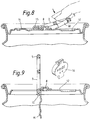
- Fig.8 shows a lifted tab; the nose has not moved enough to initiate the breaking of the score.
- the token 16 can be seen to comprise a body 17 having a profile to fit in the aperture 4, a first lateral lug 18 having a bulb ended rib portion 19, and a second lateral lug 20 which is flat and diametrically opposed to the first lug.
- the bulb ended rib 19 is gripped by the curl 5 which permits removal or tearing free of the token at after opening of the can.
- Fig.5 shows that the underside of the token, as presented to the central panel 12 of the can end, has indicia to indicate which prize a purchaser has won in a gaming scheme. If the premium offer scheme simply requires the purchaser to provide a number of tokens as proof of purchase, no indicia are needed on this underside of the token. However it may be prudent to mark one or other side of the token with a mark unique to the proprietor of the beverage bought in case two traders run similiar schemes simultaneously.
- Fig.6 shows that the token 16 may be moulded as a plurality of like tokens each connected to the next by a pair of parallel rods or feeders F1, F2.
- the array of tokens and feeders behaves as a strip for feeding to a parting apparatus.
- Fig.7 shows that each token has a central body 17 flanked by a first lug 18 and a rib 19 to one side and second lug 20 to the other side.
- the body material 17 of each token may be marked before the token shape is cut from the feeder rods F1, F2.
- Any known marking technique such as laser marking, ink jet printing, may be used to make a mark a position P.
- embossing may be used if the body material is thick enough to prevent the embossed marks showing through on the top side of tokens that are to be used for gaming.
- each token is transported by movement of the rods to a parting station, at which a cropping tool, comprising a punch indicated at C, C2 and a die (not shown), parts a token from the feeder rods.
- a cropping tool comprising a punch indicated at C, C2 and a die (not shown)
- the token 16C is at the parting station and about to be parted from the feeder rods F1, F2 by the punch (not shown) which act on the dashed lines C1, C2. Ideally the parted token is then pushed into engagement with a metal lever waiting to receive it and then the metal of the ring pull 5 is clinched onto the rib 19 to retain the token.
- Fig.8 shows a filled can of beverage at an early stage of opening.
- the pull ring has been lifted to a position at which its nose 15 has not moved enough to break the score 13.
- the token remains attached to the ring pull 5 and cannot be removed without further lever motion that would break the openable portion 14 free from the central panel 12.
- Fig.9 shows the same can as Fig.8, but at the fully open position at which the token 16 can be conveniently gripped and pulled free from the lever 3.
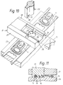
- Figs.10 and 11 show a tool for cutting an entire token from an alternative continuous extruded section, inserting the token into a part formed lever, and curling a peripheral portion of the lever to grip the first lug of the token.
- the shape of the modified extruded section can be seen in the small piece of shred falling away from the tool.
- the cross section in Fig.10 has a simple rectilinear rib at the edge of the extruded section instead of the bulb ended rib of Fig.8 as is created by the clinching operation.
- the tooling shown comprises a combined die plate and guides 21, a punch 22, and lower die block 23 of a progression tool used to form pull rings 3.
- the die plate 21 comprises elongate members 24, 25 to support the material of the first and second lugs respectively while the token body material lies flat on the surface 26 in between.
- the die plate 21 further comprises elongate side members 27, 28 which serve to reinforce the plate against bending as it crosses the lever material.
- the orifice 29 defines two sides of the token so that as the extruded section spans the orifice the peripheral surfaces of the token to be are confined on three sides by the orifice profiles and the elongate member 28.
- the punch has a shape complimentary to that of the die orifice 29 and has an extension block 30 to its lower surface that defines a curl forming profile 31. As the punch is lowered to contact the extruded section the section is confined on all sides as cropping commences. The punch passes through the die orifice to push the token into engagement with a lever below.
- Fig.11 shows a token fitted in a lever and retained therein by a portion of the lever that has been curled over the first lug by a curling profile on the punch.
- the extruded section is moved to present further material for cropping and push the shred S off the die plate 21 for recycling.
- Figs.12, 13, 14 and 15 show in detail a sequence press tool stations at which the ring pull is prepared to receive a token, a token is parted from a strip of tokens and fitted in the prepared ring pull, and then the token is retained in the ring pull by clinching peripheral metal of the ring pull onto a lug of the token.
- Fig.12 shows a tool station comprising an upper tool 35 and a lower tool 36.
- the ring pull component 37 is shown during curling of the ring pull metal to define a "finger" aperture 32.
- the ring pull component is supported on the lower tool block 36 which has a boss 39 which enters a recess in the ring pull between the nose 40 of the ring pull and the rivet receiving plate 41. This boss cooperates with a punch 42, of the upper tool, which has a curl forming profile 43, to centre the ring pull between the upper and lower tools 35, 36.
- Fig .12a the curled ring pull component 37 is shown to have a curl 38 defining the "finger” aperture and a slot 44 at the right hand end of the ring pull, as drawn, defined by an upstanding peripheral portion 45 of the peripheral curl 46 of the pull ring.
- Fig.13 shows a tool station 47 comprising an upper tool 48 and a lower tool 49 for flattening the curl made by the tools of Fig.12 so that a token may lie within the height of the ring pull.
- the ring pull component is supported on a lower tool which has a boss 50 extending between the nose 40 of the ring pull and the rivet receiving plate 41.
- the lower tool 49 also has a flat surface 51 which supports the ring portion of the pull ring and defines a recess 52 which is axially aligned with a plug member 52 of the upper tool 47.
- the plug member 53 of the upper tool is surrounded by a hollow punch 54 which cooperates with the lower tool to crush the curl 38 to a flatened curl 38 and push the upstanding peripheral portion to the required attitude to define the slot 44 to receive the lug of the token.
- the required attitude of the slot defining portion is that of a "start curl" as can be seen in Figs.13a and 13b.
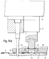
- Fig.14a shows a combined token parting and fitting station at which an upper tool 56, a lower tool 57 and a pressure plate 58 there between cooperate to part a token from a strip of token material (as shown in Fig.14b) and fit the parted token into a prepared pull ring component (as shown in Fig.14c).
- an upper tool 56 comprises a tool holder 59 from which depends a pilot peg 60 which is used to register the upper tool with shred around the ring pull component (best seen in Fig.10).
- a cutting punch 61 also depends from the tool holder for motion through the pressure plate 58 to push a parted token into a ring pull.
- the pressure plate 58 comprises a plate portion 62 defining a first aperture 63 for the pilot peg 60 and a second aperture having a stepped bore 64 to support cutting die 65 with which the cutting punch cooperates to part a token from the strip.
- Top plates 66 define with the pressure plate portion a pair of marginal slots to guide the strip and prevent it bending during cutting.
- the strip 68 of token material is a continuous extrudate having a central portion 69 flanked by offset flange or lug portions 70, 71 to each side of the central portion. I will be noticed that at the right hand side of the strip (as drawn) a further flange 72 portion is offset into the plane of the central or body portion of the strip.
- the bottom tool 57 has a substantially flat top 73 surface to support a progression of ring pulls 3 in the shred 73 of metal from which they have been stamped (best understood from Fig.10) in which pilot holes to receive the pilot peg are visible.
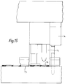
- the ring pull component with token located in it is then transferred, by motion of the ring pull shred 73, to a further station shown in Fig.15 at which the upstanding portion 45 of start curl material (created at the tool of Fig.13) is curled into clinched engagement with the lug of the token.
- an upper tool 74 has a punch 75 provided with an end profile sloped to crush the upstanding portion 45 on the right hand lug while holding left hand lug in a crushed recess 77 (best seen in Fig.13b) so that the token is held flat in the ring pull.
- the completed ring pull with token attached is passed to a tool station (not shown) at which the ring pull is fixed, by a rivet of a can end, to the centre panel of a can end in a manner well known.
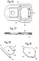
- Figs.16, 17 and 18 show an alternative token 80 which has three lugs 81, 82 83 offset from the plane of a plug portion 84 of the token.
- a first lug is clinched in the manner already described.
- the two further lugs defined by the terminal portions of the other lateral flange are clinched at the respective sides of the ring pull.
- Fig.19 shows an alternative form of token 85 cut from flat strip to have three lugs 86, 87, 88, in the same plane as a body 89, which are clinched in the same manner as the lugs of the token shown in Figs.16, 17 and 18. Whilst the token of Fig.19 is easy to make it may be more difficult to remove unless the centre of the token is dished upwards to make its top surface accessible for finger pressure applied at the finger opening of the ring pull. If the strip from which the token is cut is amenable to cold forming, eg. laminates of metal/polymer, or acrylonitrile butadiene strip, or like thermoplastics, the strip material may be stretch formed in before cutting and fitting in the ring pull to provide a useful raised centre.
- the strip material may be stretch formed in before cutting and fitting in the ring pull to provide a useful raised centre.
- the token as described above, is formed from an extruded section of polypropylene but other polymers may be used such as polyethylene or polyvinyl chloride.
- polypropylene but other polymers may be used such as polyethylene or polyvinyl chloride.
- the polymer be pigmented to prevent any risk of reading indicia through the token material.
- the token typically weighs about 0.15gm and the recyclable shred as little as 0.06gm per token made so that this invention provides a token at an acceptable cost.
- lugs Whilst the lugs, described with reference to embodiments depicted, are substantially rectilinear, it is within the scope of this invention to use lugs of arcuate outline to fit the contours of the metal lever or ring pull chosen.
Abstract
Description
- This invention relates to tokens, attached to an article of packaging, which may be used as proof of purchase of the article or for other purpose. More particularly, but not exclusively, the invention relates to a proof of purchase token attached to the lever used to open cans commonly used to contain beverages or other products, a method of fixing a token to a pull ring, and apparatus for carrying out the method.
- Pull ring can ends having a printed underside for gaming purposes were used in America until legislation in certain States banned the use of completely detachable ring pulls because the torn edge were perceived to be dangerous litter. United States Patent 4459910 (Metal Box Can/Taube) describes an embossing press used to incise numbers on the underside of the ring pull of a beverage can end, the intention being that certain numbers would qualify the purchaser to claim a prize.
- British Patent 1540229 (Reynolds Metals Co/Cudzik) describes a can end for beverage cans in which a lever attached to the can end at a hinge plate portion is used to push an openable flap down into the can and remain captive on the can end. These can ends are shown in Figs.1 and 2 of the drawing now widely used but, because the lever is captive on the can end, it cannot be removed for sales promotion and gaming purposes.
- The sales promotion games and prizes were much enjoyed and provided a useful encouragement of trade and reward for loyalty to a particluar brand of product.
- US 3958354 (Robert J Hough/BOISE CASCADE CORPORATION) describes a promotional token for attachment to the pull tab ring of an easy-open container. The token is preferably made of a synthetic plastics material to include a mounting portion, adapted for insertion in the finger opening of the ring, and connecting means for removably fastening the token mounting portion in the finger opening of the ring. The token mounting means described by HOUGH are:-
a continuous groove contained in the outer peripheral wall surface of the mounting portion to achieve a snap-fit in the finger opening (Figs.1,2,3); or lateral wing portions that extent outwardly from the mounting portion across the adjacent portions of the pull ring to achieve a snap fit (Figs.4, 5 and 6, 7); or
a plurality of resilient lug means circumferentially spaced about the periphery of a body portion of the token having an outer peripheral configuration that corresponds generally with the inner periphery of the finger opening so that the outer pheripheral surface of the token is a snap fit in the inner peripheral surface of the pull ring. - In all the embodiments described in US 3958354 the token is retained in the pull tab ring by snap fit of the token in the finger opening so that problems may arise from dimensional variations arising, during injection moulding of the resilient token material, which may spoil the snap-fit attachment to render the token too easy to remove. We believe that the most convenient time to fit a token onto a pull tab ring is before the pull ring is fitted onto the can end while the token receiving surfaces of the pull ring are accessible. However, the token must be firmly and reliably retained in the pull ring to prevent any risk of a token falling from the ring pull to cause a crash in the press which rivets the pull ring to the can end. We believe that reliable retention of the token in the pull ring is best achieved by clinching of a lateral tab of the token in the peripheral curl of the pull ring.
- In a first aspect this invention provides a token removably retained in engagement with a ring pull or lever adapted for attachment to a container wall characterised in that the token is retained in engagement with the pull ring or lever by a peripheral curl portion of the lever material. Benefits arising from peripheral grip on the token include secure retention of the token during subsequent assembly of the pull ring to a can end.
- In one embodiment the token has at least one lug extending laterally from the body of the token, and the lug is retained in engagement with the pull ring or lever by a peripheral curl portion clinched onto the lug. The benefit of clinching upon a lug resides in the localised grip which permits removal of the token from the pull ring after opening of a can.
- The token may be made of a plastics material, such as polyethylene or polypropylene or metal strip. Each of these materials is amendable to different forming techniques to make the token shapes, but in all cases the tokens are fixed to the lever by clinching.
- The token may be an injection moulding of plastics material. Alternatively, the token shape may be cut from an elongate extruded section of plastics strip, metal strip or laminate to define a token which preferably has at least one lug extending laterally from the body.
- After the token has been retained on the ring pull or lever the ring pull or lever is attached to a wall of a container, usually by staking a rivet such as is used on can ends. The token may have indicia marked on the underside facing the wall of the container to permit playing of games of chance.
- Retention of the token in the lever or ring pull maybe increased by a pair of axially aligned lugs, each of which extends away from the body of the token for retention by a peripheral curl portion at a side of the lever or pull ring, but care must be taken to avoid making the token irremovable.
- The body of the token is preferably of a shape to fit loosely inside an aperture of the lever or pull ring and present an upper token surface to the user who can then remove the token from the lever or ring pull by pressing on the upper surface.
- In a second aspect the invention provides a method of retaining a proof of purchase token in a ring pull or lever, said method being characterised by the steps of feeding a strip of material including token portions to a parting station; applying pressure to the strip to part a token from the strip and apply the parted token to the lever or ring pull; and clinching a peripheral portion of the material of the lever or ring pull into engagement with the token. The benefit of this method is that the token and receiving surface of the lever or ring pull is automatically aligned to ensure correct fitting.
- The strip of material including token portions may be formed by casting moulding thermoplastics material to comprise a pair of elongate members joined by a plurality of moulded tokens.
- Each token of the strip may be decorated, before parting from the strip by a process chosen from surface relieve formed during moulding, or embossing after moulding, or hot die stamping, or ink jet printing.
- In an alternative method, the strip of material including token portions is formed by extrusion of a single thermoplastic polymer, or as coextrusion of said thermoplastic polymer and a second polymer to make a two layer strip, or by extrusion coating a metal strip, or by lamination of a polymer to a metal strip.
- Again, indicia may be marked on the strip before each token is parted from the strip.
- In a preferred method extruded strip is formed to comprise a central web and an offset flange margin extending laterally from each side of the central web.
- The token is parted from the extruded strip by cooperation of a die and a punch which is applied to the strip to first cut out a token and then apply the token to a part formed lever or ring pull, so that a single movement of the punch not only parts the token from the strip but also applies it correctly to the lever or ring pull.
- The punch and die preferably cooperate to cut out a token having a body cut from the central web of the extruded strip and at least one lug extending laterally from the token body in a plane offset from the plane of the body after which step a peripheral portion of the lever or ring pull is curled to clinch against a peripheral portions or lug of the token so that the central web portion is held up in an aperture in the lever or ring pull. The lever ring pull with token attached, may be passed to a rivetting station at which the lever or pull rings is retained on a can end by staking of a rivet.
- In a further aspect this invention provides apparatus for retaining a proof of purchase token on a lever or ring pull, said apparatus comprising,
- (a) means to feed a strip of material including token portions to a parting station;
- (b) a parting station at which the token portion is severed from the strip of material;
- (c) means to transfer the parted token to a location in a partly formed lever or ring pull; and
- (d) means to clinch a peripheral portion of the lever into clinched engagement with a peripheral portion of the token.
- In one embodiment of the apparatus the means to part the token portion from the strip is a punch and die so arranged that after parting the token from the strip the punch pushes the token through die and into engagement with the partly formed lever or ring pull.
- In a preferred embodiment, the apparatus further comprises means to convey the lever or ring pull with token attached, to a station at which the pull ring is rivetted to a can end.
- The means to feed the strip of token material to the parting station also includes means to apply indicia to the strip. Suitable means to apply indicia to the strip include an embossing press tool, hot die stamping tool, or a printing head such as an ink jet printer. When making tokens for gaming or lotteries, the means to apply indicia, marks one of a range of indicia on each token.
- The extruded section may be marked with indicia before cropping out the token.
- Various embodiments will now be described by way of example and with reference to the accompanying drawings in which:-
- Fig.1 is a plan view of a known can end;
- Fig.2 is a side view of the can end of Fig.1 sectioned on a diameter through the lever;
- Fig.3 is an enlarged fragmentary section including a token according to this invention;
- Figs.4 and 5 are perspective views of the underside and topside of the token of Fig.3;
- Fig.6 is a plan view of a length of moulded strip plastics material showing partly cropped tokens;
- Fig.7 is an end view of the moulded material of Fig.6. sectioned through a token;
- Fig.8 is a sectioned side view of a can during opening;
- Fig.9 is a sectioned side view of the can of Fig.8 after fully opening and removal of the token;
- Fig.10 is a perspective sketch of a combined cropping and fitting tool;
- Fig.11 is a side view of the cropping tool of Fig.10 sectioned on the line of travel of the lever material;
- Fig.12 is a part sectioned side view of a curling station and pull ring;
- Fig.12a is a plan view of a pull ring after curling;
- Fig.13a is a side view of a curl flattening station;
- Figs.13b and 13c are a plan view and sectioned side view of pull ring after flattening of the curl;
- Fig.14a, 14b and 14c are side views of a token punching and fitting station at various positions in operation;
- Fig.15 is a side view of a clinching station;
- Fig.16 is a plan view of an alternative token and pull ring;
- Fig.17 is a side view of a pull ring and token sectioned on a centre line in Fig.16;
- Fig.18 is a perspective sketch of the alternative token of Figs.16 and 17; and
- Fig.19 is a perspective sketch of a modified token.
- Figs.1 and 2 show, by way of example, a can end of a kind described in GB 1540229 (REYNOLDS), to which the reader is directed for a detailed description.
- In Figs.1 and 2 it will be seen that the can end 1 comprises a can end
component 2 and alever 3 which has alarge aperture 4 at the right hand end defined by a ring oflever metal 5. - A
smaller aperture 6, defined by asquare hinge plate 7 of the lever, has permitted entering of ahollow rivet 8 into the smaller aperture and staking to fix thelever 3 on the can endcomponent 2. - The can end
component 2 comprises aperipheral flange 9 or cover hook, achuck wall 10 dependent from the interior of the cover hook, a channel shaped reinforcingbead 11 extending inwards from the chuck wall to support acentral panel 12. Therivet 8 is raised from the material of thecentral panel 12. - A
score line 13 defines an approximately "U" shapedopenable portion 14 which extends under thenose 15 of the lever but does not encompass therivet 8. - When the
ring pull end 5 of the lever is raised about therivet 8 thehinge plate 7 flexes to permit thenose 15 of the lever to break the score line and progressively open theopenable portion 14 as shown in Figs.8 and 9. - In Fig.3 like parts are denoted by the same numbers as used in Figs.1 and 2. In Fig.3 it will be seen that the
large aperture 4 is substantially filled by a token 16 which is retained in position by a crimped portion of the curledring 5. Fig.8 shows a lifted tab; the nose has not moved enough to initiate the breaking of the score. - In Figs.4 and 5 the token 16 can be seen to comprise a
body 17 having a profile to fit in theaperture 4, a firstlateral lug 18 having a bulb endedrib portion 19, and a secondlateral lug 20 which is flat and diametrically opposed to the first lug. The bulb endedrib 19 is gripped by thecurl 5 which permits removal or tearing free of the token at after opening of the can. - Fig.5 shows that the underside of the token, as presented to the
central panel 12 of the can end, has indicia to indicate which prize a purchaser has won in a gaming scheme. If the premium offer scheme simply requires the purchaser to provide a number of tokens as proof of purchase, no indicia are needed on this underside of the token. However it may be prudent to mark one or other side of the token with a mark unique to the proprietor of the beverage bought in case two traders run similiar schemes simultaneously. - Fig.6 shows that the token 16 may be moulded as a plurality of like tokens each connected to the next by a pair of parallel rods or feeders F₁, F₂. The array of tokens and feeders behaves as a strip for feeding to a parting apparatus.
- Fig.7 shows that each token has a
central body 17 flanked by afirst lug 18 and arib 19 to one side andsecond lug 20 to the other side. - If required the
body material 17 of each token may be marked before the token shape is cut from the feeder rods F₁, F₂. Any known marking technique, such as laser marking, ink jet printing, may be used to make a mark a position P. Even embossing may be used if the body material is thick enough to prevent the embossed marks showing through on the top side of tokens that are to be used for gaming. - In Fig.6, after marking of the moulded tokens each token is transported by movement of the rods to a parting station, at which a cropping tool, comprising a punch indicated at C, C2 and a die (not shown), parts a token from the feeder rods.
- The token 16C is at the parting station and about to be parted from the feeder rods F₁, F₂ by the punch (not shown) which act on the dashed lines C₁, C₂. Ideally the parted token is then pushed into engagement with a metal lever waiting to receive it and then the metal of the
ring pull 5 is clinched onto therib 19 to retain the token. - Fig.8 shows a filled can of beverage at an early stage of opening. The pull ring has been lifted to a position at which its
nose 15 has not moved enough to break thescore 13. In spite of finger pressure, it will be seen that the token remains attached to thering pull 5 and cannot be removed without further lever motion that would break theopenable portion 14 free from thecentral panel 12. - Fig.9 shows the same can as Fig.8, but at the fully open position at which the token 16 can be conveniently gripped and pulled free from the
lever 3. - Figs.10 and 11 show a tool for cutting an entire token from an alternative continuous extruded section, inserting the token into a part formed lever, and curling a peripheral portion of the lever to grip the first lug of the token.
- The shape of the modified extruded section can be seen in the small piece of shred falling away from the tool. The cross section in Fig.10 has a simple rectilinear rib at the edge of the extruded section instead of the bulb ended rib of Fig.8 as is created by the clinching operation.
- In Fig.10 the tooling shown comprises a combined die plate and guides 21, a
punch 22, andlower die block 23 of a progression tool used to form pull rings 3. - The
die plate 21 compriseselongate members 24, 25 to support the material of the first and second lugs respectively while the token body material lies flat on thesurface 26 in between. Thedie plate 21 further compriseselongate side members - The
orifice 29 defines two sides of the token so that as the extruded section spans the orifice the peripheral surfaces of the token to be are confined on three sides by the orifice profiles and theelongate member 28. - The punch has a shape complimentary to that of the
die orifice 29 and has anextension block 30 to its lower surface that defines acurl forming profile 31. As the punch is lowered to contact the extruded section the section is confined on all sides as cropping commences. The punch passes through the die orifice to push the token into engagement with a lever below. - Fig.11 shows a token fitted in a lever and retained therein by a portion of the lever that has been curled over the first lug by a curling profile on the punch.
- As the lever is passed along the
die block 23 of its progression tool, the extruded section is moved to present further material for cropping and push the shred S off thedie plate 21 for recycling. - Figs.12, 13, 14 and 15 show in detail a sequence press tool stations at which the ring pull is prepared to receive a token, a token is parted from a strip of tokens and fitted in the prepared ring pull, and then the token is retained in the ring pull by clinching peripheral metal of the ring pull onto a lug of the token.
- Fig.12 shows a tool station comprising an
upper tool 35 and alower tool 36. In Fig.12a thering pull component 37 is shown during curling of the ring pull metal to define a "finger" aperture 32. The ring pull component is supported on thelower tool block 36 which has aboss 39 which enters a recess in the ring pull between thenose 40 of the ring pull and therivet receiving plate 41. This boss cooperates with apunch 42, of the upper tool, which has acurl forming profile 43, to centre the ring pull between the upper andlower tools - In Fig .12a the curled
ring pull component 37 is shown to have acurl 38 defining the "finger" aperture and aslot 44 at the right hand end of the ring pull, as drawn, defined by an upstandingperipheral portion 45 of theperipheral curl 46 of the pull ring. - Fig.13 shows a
tool station 47 comprising anupper tool 48 and alower tool 49 for flattening the curl made by the tools of Fig.12 so that a token may lie within the height of the ring pull. In Fig.13a the ring pull component is supported on a lower tool which has aboss 50 extending between thenose 40 of the ring pull and therivet receiving plate 41. Thelower tool 49 also has aflat surface 51 which supports the ring portion of the pull ring and defines arecess 52 which is axially aligned with aplug member 52 of theupper tool 47. Theplug member 53 of the upper tool is surrounded by ahollow punch 54 which cooperates with the lower tool to crush thecurl 38 to aflatened curl 38 and push the upstanding peripheral portion to the required attitude to define theslot 44 to receive the lug of the token. - The required attitude of the slot defining portion is that of a "start curl" as can be seen in Figs.13a and 13b.
- Fig.14a shows a combined token parting and fitting station at which an
upper tool 56, alower tool 57 and apressure plate 58 there between cooperate to part a token from a strip of token material (as shown in Fig.14b) and fit the parted token into a prepared pull ring component (as shown in Fig.14c). - In Fig.14a an
upper tool 56 comprises atool holder 59 from which depends apilot peg 60 which is used to register the upper tool with shred around the ring pull component (best seen in Fig.10). A cuttingpunch 61 also depends from the tool holder for motion through thepressure plate 58 to push a parted token into a ring pull. - The
pressure plate 58 comprises aplate portion 62 defining afirst aperture 63 for thepilot peg 60 and a second aperture having a stepped bore 64 to support cutting die 65 with which the cutting punch cooperates to part a token from the strip.Top plates 66 define with the pressure plate portion a pair of marginal slots to guide the strip and prevent it bending during cutting. - The
strip 68 of token material is a continuous extrudate having acentral portion 69 flanked by offset flange or lugportions further flange 72 portion is offset into the plane of the central or body portion of the strip. - The
bottom tool 57 has a substantially flat top 73 surface to support a progression of ring pulls 3 in theshred 73 of metal from which they have been stamped (best understood from Fig.10) in which pilot holes to receive the pilot peg are visible. - In Fig.14b the upper tool has been lowered so that
pressure plate 58 holds the pull rings, and their shred, flat, while thepilot peg 60 is engaged with a register hole, thering pull shred 73 and the cuttingpunch 61 is about to cooperate with the die 65 to cut out a token from the strip and push it, via the position shown by dashed lines, through the die to aprepared ring pull 3 waiting to receive it, as is shown in Fig.14c. - The ring pull component with token located in it is then transferred, by motion of the
ring pull shred 73, to a further station shown in Fig.15 at which theupstanding portion 45 of start curl material (created at the tool of Fig.13) is curled into clinched engagement with the lug of the token. In Fig.15 anupper tool 74 has apunch 75 provided with an end profile sloped to crush theupstanding portion 45 on the right hand lug while holding left hand lug in a crushed recess 77 (best seen in Fig.13b) so that the token is held flat in the ring pull. - The completed ring pull with token attached is passed to a tool station (not shown) at which the ring pull is fixed, by a rivet of a can end, to the centre panel of a can end in a manner well known.
- The crimping of a peripheral portion of the ring pull onto a localised lug of the token has been described because it is believed that, on opening of a can fitted with these ring pulls, removal of a lug will be easier than removal of a completely clinched periphery of a token with no lugs. However, careful clinching could provide a viable arrangement if desired.
- Figs.16, 17 and 18 show an
alternative token 80 which has threelugs plug portion 84 of the token. A first lug is clinched in the manner already described. The two further lugs defined by the terminal portions of the other lateral flange are clinched at the respective sides of the ring pull. - Fig.19 shows an alternative form of
token 85 cut from flat strip to have threelugs - The token, as described above, is formed from an extruded section of polypropylene but other polymers may be used such as polyethylene or polyvinyl chloride. For gaming tokens it is preferable that the polymer be pigmented to prevent any risk of reading indicia through the token material.
- The token typically weighs about 0.15gm and the recyclable shred as little as 0.06gm per token made so that this invention provides a token at an acceptable cost.
- Whilst the lugs, described with reference to embodiments depicted, are substantially rectilinear, it is within the scope of this invention to use lugs of arcuate outline to fit the contours of the metal lever or ring pull chosen.
- It will be understood that this invention may be applied to any container having a token fixed in the manner described.
Claims (25)
- A token or the like removably retained in engagement with a ring pull or lever adapted for attachment to a container wall characterised in that the token is retained in engagement with the pull ring or lever by a peripheral curl portion of the lever material.
- A token according to claim 1, wherein the token has at least one lug extending laterally from the body of the token, and the lug is retained in engagement with the pull ring or lever by a peripheral curl portion clinched onto the lug.
- A token according to claim 1 or claim 2 wherein the token is made of a plastics material, such as polyethylene or polypropylene or metal strip.
- A token according to claim 3 wherein the token is an injection moulding of plastics material.
- A token according to claim 3 wherein the token is of a shape, cut from an elongate extruded section of plastics strip or metal strip to define said at least one lug.
- A token according to any preceding claim when retained on the ring pull or lever and the ring pull or lever is attached to wall of a container.
- A token according to claim 6 wherein the token has indicia marked on the underside facing the wall of the container.
- A token according to any preceding claim having a pair of axially aligned lugs each of which extends away from the body of the token for retention by a peripheral curl portion at a side of the lever or pull ring.
- A token according to any preceding claim wherein the body of the token is of a shape to fit inside an aperture of the lever or pull ring and present an upper token surface to the user.
- A method of retaining a token in a ring pull or lever, said method being characterised by the steps of feeding a strip of material including token portions to a parting station, applying pressure to the strip to part a token from the strip and apply the parted token to the lever or ring pull, and clinching a peripheral portion of the material of the lever or ring pull into engagement with the token.
- A method according to claim 10, wherein the strip of material including token portions is formed by casting or moulding a pair of elongate members as feeders joined by a plurality of moulded tokens.
- A method according to claim 11 wherein each token of the strip is decorated, before parting from the strip, by a process chosen from surface relief formed during moulding, or embossing after moulding, or hot die stamping.
- A method according to claim 10 wherein the strip of material including token portions is formed by extrusion of a single thermoplastic polymer, or as coextrusion of said thermoplastics polymer and a second polymer to make a two layer strip, or by extrusion coating a metal strip, or by lamination of a poolymer to a metal strip.
- A method according to claim 13 wherein indicia are marked on the strip before each token is parted from the strip.
- A method according to claim 13 or claim 14 wherein the strip is formed to comprise a central web and an offset flange margin extending laterally from each side of the central web.
- A method according to any one of claims 13 to 15, wherein the token is parted from the strip to first cut out a token and then the token is applied to a part formed lever or ring pull.
- A method according to claim 16 when dependent on claim 15 which the punch and die cooperate to cut out a token having a body cut from the central web and at least one lug extending laterally from the token body in a plane offset from the plane of the body.
- A method according to any one of claims 10 to 17, wherein a periphral portion of the lever or ring pull is curled to clinch against a peripheral portion or lug of the token.
- A method according to any one of claims 10 to 18, wherein the lever ring pull with token attached, is passed to a rivetting station at which the lever or pull rings retained on the can end by staking of a rivet.
- Apparatus for retaining a token on a lever or ring pull said apparatus comprising:(a) means to feed a strip of material including token portions to a parting station;(b) a parting station at which the token portion is severed from the strip of material;(c) means to transfer the parted token to a location in a partly formed lever or ring pull; and(d) means to clinch a peripheral portion of the lever into clinched engagement with a peripheral portion of the token.
- Apparatus according to claim 20 wherein the means to part the token portion from the strip is a punch and die so arranged that after parting the token from the strip the punch pushes the token through die and into engagement with the partly formed lever or ring pull.
- Apparatus according to claim 20 or claim 21 wherein the apparatus further comprises means to convey the lever or ring pull with token attached to a station at which the pull ring is rivetted to a can end.
- Apparatus according to any one of claims 20 to 22, wherein the means to feed the strip of token material to the parting station also includes means to apply indicia to the strip.
- Apparatus according to claim 23 wherein the means to apply indicia to the strip is an embossing press tool, hot die stamping tool, or printing head.
- Apparatus according to claim 24 wherein the means to apply indicia, marks a one of the range of indicia on each token.
Applications Claiming Priority (2)
| Application Number | Priority Date | Filing Date | Title |
|---|---|---|---|
| GB909023243A GB9023243D0 (en) | 1990-10-25 | 1990-10-25 | Containers |
| GB9023243 | 1990-10-25 |
Publications (2)
| Publication Number | Publication Date |
|---|---|
| EP0482776A1 true EP0482776A1 (en) | 1992-04-29 |
| EP0482776B1 EP0482776B1 (en) | 1994-06-08 |
Family
ID=10684342
Family Applications (1)
| Application Number | Title | Priority Date | Filing Date |
|---|---|---|---|
| EP91308977A Expired - Lifetime EP0482776B1 (en) | 1990-10-25 | 1991-10-01 | Token for use in pull-tab ring openers of containers |
Country Status (13)
| Country | Link |
|---|---|
| US (3) | US5191695A (en) |
| EP (1) | EP0482776B1 (en) |
| AU (1) | AU643561B2 (en) |
| DE (1) | DE69102390T2 (en) |
| ES (1) | ES2057778T3 (en) |
| GB (2) | GB9023243D0 (en) |
| HK (1) | HK98395A (en) |
| IE (1) | IE64862B1 (en) |
| NZ (1) | NZ240252A (en) |
| PT (1) | PT99321B (en) |
| TR (1) | TR26239A (en) |
| TW (1) | TW249788B (en) |
| ZA (1) | ZA918012B (en) |
Cited By (21)
| Publication number | Priority date | Publication date | Assignee | Title |
|---|---|---|---|---|
| US5482158A (en) * | 1994-11-23 | 1996-01-09 | The Coca-Cola Company | Promotional device for delivering a prize from a beverage can |
| US5655678A (en) * | 1994-02-25 | 1997-08-12 | Kobayashi; Tadao | Container opening device with bend-supporting portion |
| US5728415A (en) * | 1995-07-19 | 1998-03-17 | The Coca-Cola Company | Prize-containing beverage can |
| WO1998010945A1 (en) * | 1996-09-10 | 1998-03-19 | Schmalbach-Lubeca Ag | A metallic object provided with areas of contrasting appearance |
| GB2320008A (en) * | 1996-12-09 | 1998-06-10 | Cadbury Schweppes Plc | Container closure which carries data |
| WO1999009853A3 (en) * | 1997-08-26 | 1999-05-27 | Joseph W Stasiuk | Decorative and symbolically shaped pull tab container opening devices and methods of making the same |
| US6056116A (en) * | 1997-12-24 | 2000-05-02 | The Coca-Cola Company | Noise suppressed prize dispenser for a container |
| US6105806A (en) * | 1997-08-26 | 2000-08-22 | Stasiuk; Joseph W. | Laser etched pull tab container opening devices and methods of making the same |
| US6433302B1 (en) | 1998-07-16 | 2002-08-13 | Ball Corporation | Method and apparatus for marking containers using laser light |
| US6455806B1 (en) | 2000-01-14 | 2002-09-24 | Rexam Ab | Arrangement for shaping and marking a target |
| US6476349B1 (en) | 1998-04-28 | 2002-11-05 | Rexam Ab | Strip guiding device |
| US6479787B1 (en) | 1999-10-05 | 2002-11-12 | Rexam Ab | Laser unit and method for engraving articles to be included in cans |
| US6576871B1 (en) | 2000-04-03 | 2003-06-10 | Rexam Ab | Method and device for dust protection in a laser processing apparatus |
| KR20040017006A (en) * | 2002-08-20 | 2004-02-26 | 주식회사 봉정캔텍 | Improvements in can opening tab for use in beverage can |
| US6706995B2 (en) | 1998-07-16 | 2004-03-16 | Ball Corporation | Laser light marking of a container portion |
| US6872913B1 (en) | 2000-01-14 | 2005-03-29 | Rexam Ab | Marking of articles to be included in cans |
| US6926456B1 (en) | 2000-01-20 | 2005-08-09 | Rexam Ab | Guiding device for a marking arrangement |
| EP1588333A1 (en) * | 2003-01-21 | 2005-10-26 | Michael Zoche - Antriebstechnik | Can for deposit system and method for developing said deposit system |
| EP1590108A1 (en) * | 2003-01-15 | 2005-11-02 | Kian Joo Packaging SDN BHD | Method for providing marking on the pull tab of a can end |
| WO2011070107A1 (en) | 2009-12-09 | 2011-06-16 | Crown Packaging Technology, Inc. | Can end with film insert |
| EP2660040A1 (en) * | 2012-05-03 | 2013-11-06 | Bayer MaterialScience AG | Multi-layered compound material for producing blanks for coins |
Families Citing this family (29)
| Publication number | Priority date | Publication date | Assignee | Title |
|---|---|---|---|---|
| US5564714A (en) * | 1993-02-23 | 1996-10-15 | Three Bond Co., Ltd. | Rubber-like molded product with support frame |
| US5775534C1 (en) * | 1995-11-24 | 2001-01-02 | Michael Reginald Webb | Beverage container having filtered opening |
| US5996832A (en) * | 1996-06-26 | 1999-12-07 | Henbase 3172 (Proprietary) Limited | Cover for beverage can |
| US5799815A (en) * | 1996-11-25 | 1998-09-01 | Tony David | Device and kit for identifying pop-top cans |
| US20010011431A1 (en) | 1998-11-25 | 2001-08-09 | Elias Brian K. | Method and apparatus for conveying unique visual communication |
| US6138856A (en) * | 1999-04-29 | 2000-10-31 | Ghim; Yongjae | Container end closure |
| SG92640A1 (en) | 1999-06-07 | 2002-11-19 | E Pak Resources S Pte Ltd | Stud and rider for use on matrix trays |
| BE1014393A3 (en) | 2000-03-13 | 2003-10-07 | Stasiuk Joseph W | Container opening device consisting of a laser etched pull tab engraved with product information. |
| US6460719B1 (en) * | 2000-04-17 | 2002-10-08 | Brian E. Finmark | Cover for a tab top can and method of use |
| KR100397459B1 (en) * | 2000-09-21 | 2003-09-13 | 주식회사 씨솔루션 | Method and apparatus for sticking a character sticker in a tap of drinking can |
| KR100414528B1 (en) * | 2001-04-20 | 2004-01-07 | 주식회사 씨솔루션 | Method of manufacturing an aluminum design tab end for a beverage can |
| KR20010088955A (en) * | 2001-08-23 | 2001-09-29 | 정형동 | Tab having score line on a tab hole panel portion and method of manufacturing it |
| US7294056B2 (en) * | 2002-12-23 | 2007-11-13 | Gametech International, Inc. | Enhanced gaming system |
| US20050045637A1 (en) * | 2003-08-28 | 2005-03-03 | Rainer Rohr | Containers having distinctive tabs with laser etching and void forming a promotional image |
| WO2005056466A2 (en) * | 2003-12-04 | 2005-06-23 | Osterberg Brian J | Combination beverage service item and condom holder |
| JP4257194B2 (en) * | 2003-12-10 | 2009-04-22 | 片山工業株式会社 | Vehicle door sash and manufacturing method thereof |
| US20050258175A1 (en) * | 2004-05-21 | 2005-11-24 | Robertson Associates Llc | Pull tab and method |
| US20070158225A1 (en) * | 2006-01-09 | 2007-07-12 | Rexam Beverage Can Co. | Multi-pack container arrangements |
| US20090001092A1 (en) * | 2007-06-29 | 2009-01-01 | Mary Jenkins | Reusable Seal for Beverage Container |
| CA2638287A1 (en) * | 2007-07-26 | 2009-01-26 | Richard Hall | Coated lift-tab for resealing pop-top containers |
| US20090214322A1 (en) * | 2008-02-24 | 2009-08-27 | Ilan Oraizer | Method and Device for Opening Cans |
| US8146768B2 (en) * | 2009-02-04 | 2012-04-03 | Rexam Beverage Can Company | Tab with emboss and deboss beads |
| AT508144B1 (en) * | 2009-06-30 | 2010-11-15 | Teich Ag | PROCESS FOR PRODUCING PACKAGED PLATINES |
| US8844747B2 (en) * | 2010-03-19 | 2014-09-30 | Rexam Beverage Can Company | And temperature indicating can ends and tabs |
| US20130075401A1 (en) | 2011-09-23 | 2013-03-28 | Rexam Beverage Can Company | Stay-on tab for a beverage container |
| US8695245B2 (en) | 2011-11-28 | 2014-04-15 | Christopher P. Schorre | Wing shaped beverage can pull tab |
| USD781707S1 (en) | 2011-11-28 | 2017-03-21 | WingTab LLC | Beverage can pull tab |
| US9186924B2 (en) | 2012-04-17 | 2015-11-17 | Rexam Beverage Can Company | Decorated beverage can tabs |
| JP6990050B2 (en) * | 2017-06-28 | 2022-01-12 | ユニバーサル製缶株式会社 | Tabs for opening cans and can lids |
Citations (6)
| Publication number | Priority date | Publication date | Assignee | Title |
|---|---|---|---|---|
| US3097423A (en) * | 1960-10-11 | 1963-07-16 | American Can Co | Method of producing stressed joint plastic containers |
| US3958354A (en) * | 1973-01-09 | 1976-05-25 | Hough Robert J | Promotional token for a pull tab ring opener |
| US4322016A (en) * | 1979-08-10 | 1982-03-30 | The Coca-Cola Company | Proof-of-purchase means for self-opening cans |
| US4380129A (en) * | 1981-09-09 | 1983-04-19 | The Coca-Cola Company | Proof-of-purchase for self-opening cans |
| EP0080775A2 (en) * | 1981-11-27 | 1983-06-08 | Crown Cork & Seal Company, Inc. | Container closure |
| US4804105A (en) * | 1988-04-11 | 1989-02-14 | Citrus Central, Inc. | Method for fabricating burr-free pull tabs and articles |
Family Cites Families (5)
| Publication number | Priority date | Publication date | Assignee | Title |
|---|---|---|---|---|
| JPS5434541B2 (en) * | 1972-12-22 | 1979-10-27 | ||
| US3822496A (en) * | 1973-08-23 | 1974-07-09 | D Minder | Display plate for openers of pre-scored cans |
| US4363179A (en) * | 1981-07-27 | 1982-12-14 | Crown Cork & Seal Company, Inc. | Promotional can end |
| US4685849A (en) * | 1985-05-29 | 1987-08-11 | Aluminum Company Of America | Method for making an easy opening container end closure |
| US4880137A (en) * | 1988-06-15 | 1989-11-14 | Wells Robert A | Reclosable self-opening can end |
-
1990
- 1990-10-25 GB GB909023243A patent/GB9023243D0/en active Pending
-
1991
- 1991-10-01 EP EP91308977A patent/EP0482776B1/en not_active Expired - Lifetime
- 1991-10-01 ES ES91308977T patent/ES2057778T3/en not_active Expired - Lifetime
- 1991-10-01 DE DE69102390T patent/DE69102390T2/en not_active Expired - Fee Related
- 1991-10-01 GB GB9120823A patent/GB2249538B/en not_active Expired - Fee Related
- 1991-10-07 ZA ZA918012A patent/ZA918012B/en unknown
- 1991-10-09 AU AU85663/91A patent/AU643561B2/en not_active Ceased
- 1991-10-14 TR TR91/0975A patent/TR26239A/en unknown
- 1991-10-16 IE IE363091A patent/IE64862B1/en not_active IP Right Cessation
- 1991-10-16 NZ NZ240252A patent/NZ240252A/en unknown
- 1991-10-17 TW TW082110760A patent/TW249788B/zh active
- 1991-10-23 US US07/781,693 patent/US5191695A/en not_active Expired - Fee Related
- 1991-10-24 PT PT99321A patent/PT99321B/en not_active IP Right Cessation
-
1992
- 1992-12-22 US US07/993,606 patent/US5316166A/en not_active Expired - Fee Related
- 1992-12-22 US US07/995,017 patent/US5359766A/en not_active Expired - Fee Related
-
1995
- 1995-06-22 HK HK98395A patent/HK98395A/en not_active IP Right Cessation
Patent Citations (6)
| Publication number | Priority date | Publication date | Assignee | Title |
|---|---|---|---|---|
| US3097423A (en) * | 1960-10-11 | 1963-07-16 | American Can Co | Method of producing stressed joint plastic containers |
| US3958354A (en) * | 1973-01-09 | 1976-05-25 | Hough Robert J | Promotional token for a pull tab ring opener |
| US4322016A (en) * | 1979-08-10 | 1982-03-30 | The Coca-Cola Company | Proof-of-purchase means for self-opening cans |
| US4380129A (en) * | 1981-09-09 | 1983-04-19 | The Coca-Cola Company | Proof-of-purchase for self-opening cans |
| EP0080775A2 (en) * | 1981-11-27 | 1983-06-08 | Crown Cork & Seal Company, Inc. | Container closure |
| US4804105A (en) * | 1988-04-11 | 1989-02-14 | Citrus Central, Inc. | Method for fabricating burr-free pull tabs and articles |
Cited By (26)
| Publication number | Priority date | Publication date | Assignee | Title |
|---|---|---|---|---|
| US5655678A (en) * | 1994-02-25 | 1997-08-12 | Kobayashi; Tadao | Container opening device with bend-supporting portion |
| US5482158A (en) * | 1994-11-23 | 1996-01-09 | The Coca-Cola Company | Promotional device for delivering a prize from a beverage can |
| US5728415A (en) * | 1995-07-19 | 1998-03-17 | The Coca-Cola Company | Prize-containing beverage can |
| WO1998010945A1 (en) * | 1996-09-10 | 1998-03-19 | Schmalbach-Lubeca Ag | A metallic object provided with areas of contrasting appearance |
| GB2320008B (en) * | 1996-12-09 | 2001-03-21 | Cadbury Schweppes Plc | Containers |
| GB2320008A (en) * | 1996-12-09 | 1998-06-10 | Cadbury Schweppes Plc | Container closure which carries data |
| WO1999009853A3 (en) * | 1997-08-26 | 1999-05-27 | Joseph W Stasiuk | Decorative and symbolically shaped pull tab container opening devices and methods of making the same |
| US6105806A (en) * | 1997-08-26 | 2000-08-22 | Stasiuk; Joseph W. | Laser etched pull tab container opening devices and methods of making the same |
| US6056116A (en) * | 1997-12-24 | 2000-05-02 | The Coca-Cola Company | Noise suppressed prize dispenser for a container |
| US6476349B1 (en) | 1998-04-28 | 2002-11-05 | Rexam Ab | Strip guiding device |
| US6433302B1 (en) | 1998-07-16 | 2002-08-13 | Ball Corporation | Method and apparatus for marking containers using laser light |
| US6706995B2 (en) | 1998-07-16 | 2004-03-16 | Ball Corporation | Laser light marking of a container portion |
| US6501046B1 (en) | 1998-07-16 | 2002-12-31 | Ball Corporation | Method and apparatus for marking containers using laser light |
| US6498318B1 (en) | 1998-07-16 | 2002-12-24 | Ball Corporation | Method and apparatus for marking containers using laser light |
| US6479787B1 (en) | 1999-10-05 | 2002-11-12 | Rexam Ab | Laser unit and method for engraving articles to be included in cans |
| US6455806B1 (en) | 2000-01-14 | 2002-09-24 | Rexam Ab | Arrangement for shaping and marking a target |
| US6872913B1 (en) | 2000-01-14 | 2005-03-29 | Rexam Ab | Marking of articles to be included in cans |
| US6926456B1 (en) | 2000-01-20 | 2005-08-09 | Rexam Ab | Guiding device for a marking arrangement |
| US6576871B1 (en) | 2000-04-03 | 2003-06-10 | Rexam Ab | Method and device for dust protection in a laser processing apparatus |
| KR20040017006A (en) * | 2002-08-20 | 2004-02-26 | 주식회사 봉정캔텍 | Improvements in can opening tab for use in beverage can |
| EP1590108A1 (en) * | 2003-01-15 | 2005-11-02 | Kian Joo Packaging SDN BHD | Method for providing marking on the pull tab of a can end |
| EP1590108A4 (en) * | 2003-01-15 | 2008-04-30 | Kian Joo Packaging Sdn Bhd | Method for providing marking on the pull tab of a can end |
| EP1588333A1 (en) * | 2003-01-21 | 2005-10-26 | Michael Zoche - Antriebstechnik | Can for deposit system and method for developing said deposit system |
| WO2011070107A1 (en) | 2009-12-09 | 2011-06-16 | Crown Packaging Technology, Inc. | Can end with film insert |
| US8998028B2 (en) | 2009-12-09 | 2015-04-07 | Crown Packaging Technology, Inc. | Can end with film insert |
| EP2660040A1 (en) * | 2012-05-03 | 2013-11-06 | Bayer MaterialScience AG | Multi-layered compound material for producing blanks for coins |
Also Published As
| Publication number | Publication date |
|---|---|
| PT99321A (en) | 1994-01-31 |
| DE69102390T2 (en) | 1995-02-02 |
| DE69102390D1 (en) | 1994-07-14 |
| US5316166A (en) | 1994-05-31 |
| TR26239A (en) | 1995-02-15 |
| US5191695A (en) | 1993-03-09 |
| IE913630A1 (en) | 1992-05-22 |
| HK98395A (en) | 1995-06-30 |
| NZ240252A (en) | 1993-05-26 |
| AU643561B2 (en) | 1993-11-18 |
| AU8566391A (en) | 1992-04-30 |
| GB2249538B (en) | 1994-08-24 |
| EP0482776B1 (en) | 1994-06-08 |
| ES2057778T3 (en) | 1994-10-16 |
| TW249788B (en) | 1995-06-21 |
| GB9023243D0 (en) | 1990-12-05 |
| US5359766A (en) | 1994-11-01 |
| GB2249538A (en) | 1992-05-13 |
| PT99321B (en) | 1999-02-26 |
| IE64862B1 (en) | 1995-09-06 |
| GB9120823D0 (en) | 1991-11-13 |
| ZA918012B (en) | 1992-07-29 |
Similar Documents
| Publication | Publication Date | Title |
|---|---|---|
| US5359766A (en) | Containers | |
| EP1663794B1 (en) | Containers having distinctive tabs with laser etching and void forming a promotional image | |
| US6105806A (en) | Laser etched pull tab container opening devices and methods of making the same | |
| US6808351B1 (en) | Method and apparatus for printing | |
| AU733461B2 (en) | Decorative and symbolically shaped pull tab container opening devices and methods of making the same | |
| US8146768B2 (en) | Tab with emboss and deboss beads | |
| US4380129A (en) | Proof-of-purchase for self-opening cans | |
| JP2560682Y2 (en) | Easy opening can lid | |
| JPH05147648A (en) | Token provided in container | |
| JP2569765Y2 (en) | Easy opening can lid | |
| JPH0568831U (en) | Easy opening can lid | |
| GB2578894A (en) | Tab press and method of marking indicia on tab stock | |
| MXPA00001965A (en) | Decorative and symbolically shaped pull tab container opening devices and methods of making the same | |
| JPH0562429U (en) | Easy opening can lid | |
| JPH0627552U (en) | Easy opening can lid |
Legal Events
| Date | Code | Title | Description |
|---|---|---|---|
| PUAI | Public reference made under article 153(3) epc to a published international application that has entered the european phase |
Free format text: ORIGINAL CODE: 0009012 |
|
| 17P | Request for examination filed |
Effective date: 19911016 |
|
| AK | Designated contracting states |
Kind code of ref document: A1 Designated state(s): BE DE ES FR GB GR IT LU NL SE |
|
| 17Q | First examination report despatched |
Effective date: 19930426 |
|
| GRAA | (expected) grant |
Free format text: ORIGINAL CODE: 0009210 |
|
| RAP1 | Party data changed (applicant data changed or rights of an application transferred) |
Owner name: CARNAUDMETALBOX PLC |
|
| AK | Designated contracting states |
Kind code of ref document: B1 Designated state(s): BE DE ES FR GB GR IT LU NL SE |
|
| PG25 | Lapsed in a contracting state [announced via postgrant information from national office to epo] |
Ref country code: NL Effective date: 19940608 Ref country code: GR Free format text: LAPSE BECAUSE OF FAILURE TO SUBMIT A TRANSLATION OF THE DESCRIPTION OR TO PAY THE FEE WITHIN THE PRESCRIBED TIME-LIMIT Effective date: 19940608 Ref country code: BE Effective date: 19940608 |
|
| REF | Corresponds to: |
Ref document number: 69102390 Country of ref document: DE Date of ref document: 19940714 |
|
| ET | Fr: translation filed | ||
| ITF | It: translation for a ep patent filed |
Owner name: JACOBACCI CASETTA & PERANI S.P.A. |
|
| PG25 | Lapsed in a contracting state [announced via postgrant information from national office to epo] |
Ref country code: SE Effective date: 19940908 |
|
| REG | Reference to a national code |
Ref country code: ES Ref legal event code: FG2A Ref document number: 2057778 Country of ref document: ES Kind code of ref document: T3 |
|
| REG | Reference to a national code |
Ref country code: GB Ref legal event code: 729S |
|
| PG25 | Lapsed in a contracting state [announced via postgrant information from national office to epo] |
Ref country code: LU Free format text: LAPSE BECAUSE OF NON-PAYMENT OF DUE FEES Effective date: 19941031 |
|
| NLV1 | Nl: lapsed or annulled due to failure to fulfill the requirements of art. 29p and 29m of the patents act | ||
| PG25 | Lapsed in a contracting state [announced via postgrant information from national office to epo] |
Ref country code: GB Effective date: 19950214 |
|
| REG | Reference to a national code |
Ref country code: GB Ref legal event code: 729G |
|
| PLBE | No opposition filed within time limit |
Free format text: ORIGINAL CODE: 0009261 |
|
| STAA | Information on the status of an ep patent application or granted ep patent |
Free format text: STATUS: NO OPPOSITION FILED WITHIN TIME LIMIT |
|
| 26N | No opposition filed | ||
| PGFP | Annual fee paid to national office [announced via postgrant information from national office to epo] |
Ref country code: FR Payment date: 19960911 Year of fee payment: 6 |
|
| PGFP | Annual fee paid to national office [announced via postgrant information from national office to epo] |
Ref country code: DE Payment date: 19960923 Year of fee payment: 6 |
|
| PGFP | Annual fee paid to national office [announced via postgrant information from national office to epo] |
Ref country code: ES Payment date: 19961014 Year of fee payment: 6 |
|
| PG25 | Lapsed in a contracting state [announced via postgrant information from national office to epo] |
Ref country code: ES Free format text: LAPSE BECAUSE OF EXPIRATION OF PROTECTION Effective date: 19971002 |
|
| PG25 | Lapsed in a contracting state [announced via postgrant information from national office to epo] |
Ref country code: FR Free format text: THE PATENT HAS BEEN ANNULLED BY A DECISION OF A NATIONAL AUTHORITY Effective date: 19971031 |
|
| PG25 | Lapsed in a contracting state [announced via postgrant information from national office to epo] |
Ref country code: DE Free format text: LAPSE BECAUSE OF NON-PAYMENT OF DUE FEES Effective date: 19980701 |
|
| REG | Reference to a national code |
Ref country code: FR Ref legal event code: ST |
|
| REG | Reference to a national code |
Ref country code: ES Ref legal event code: FD2A Effective date: 20010201 |
|
| PG25 | Lapsed in a contracting state [announced via postgrant information from national office to epo] |
Ref country code: IT Free format text: LAPSE BECAUSE OF NON-PAYMENT OF DUE FEES;WARNING: LAPSES OF ITALIAN PATENTS WITH EFFECTIVE DATE BEFORE 2007 MAY HAVE OCCURRED AT ANY TIME BEFORE 2007. THE CORRECT EFFECTIVE DATE MAY BE DIFFERENT FROM THE ONE RECORDED. Effective date: 20051001 |