EP0470199B1 - Clock synchronisation in a computer system - Google Patents
Clock synchronisation in a computer system Download PDFInfo
- Publication number
- EP0470199B1 EP0470199B1 EP90908115A EP90908115A EP0470199B1 EP 0470199 B1 EP0470199 B1 EP 0470199B1 EP 90908115 A EP90908115 A EP 90908115A EP 90908115 A EP90908115 A EP 90908115A EP 0470199 B1 EP0470199 B1 EP 0470199B1
- Authority
- EP
- European Patent Office
- Prior art keywords
- time
- clock
- units
- message
- data
- Prior art date
- Legal status (The legal status is an assumption and is not a legal conclusion. Google has not performed a legal analysis and makes no representation as to the accuracy of the status listed.)
- Expired - Lifetime
Links
Images

Classifications
-
- G—PHYSICS
- G06—COMPUTING; CALCULATING OR COUNTING
- G06F—ELECTRIC DIGITAL DATA PROCESSING
- G06F1/00—Details not covered by groups G06F3/00 - G06F13/00 and G06F21/00
- G06F1/04—Generating or distributing clock signals or signals derived directly therefrom
- G06F1/12—Synchronisation of different clock signals provided by a plurality of clock generators
-
- G—PHYSICS
- G04—HOROLOGY
- G04G—ELECTRONIC TIME-PIECES
- G04G7/00—Synchronisation
-
- G—PHYSICS
- G06—COMPUTING; CALCULATING OR COUNTING
- G06F—ELECTRIC DIGITAL DATA PROCESSING
- G06F1/00—Details not covered by groups G06F3/00 - G06F13/00 and G06F21/00
- G06F1/04—Generating or distributing clock signals or signals derived directly therefrom
- G06F1/14—Time supervision arrangements, e.g. real time clock
Definitions
- the present invention relates to an arrangement according to the precharacterizing clause of claim 1.
- the invention also relates to an arrangement in a machinery and/or processing system according to claim 6.
- the arrangement comprises a common serial data communication channel and two or more collaborating units which exchanges messages and which get access to the channel by priority procedures, in which a message having higher priority gets access to the channel over a message having lower priority.
- each unit having a communication circuit and being connected to the channel via its communication circuit.
- An appointed message is transferred between the units after the transmission of a preceding message which prohibits the other unit or all other units to effect communication on the channel, or alternatively when the appointed message gets access by means of said priority procedures.
- Each unit of said units is arranged to provide data associated with events or produces events associated with data and said data are included in messages which are to be transferred on the channel.
- the receiving unit can check that the data has arrived within the arranged time frame.
- it can be difficult to estimate and/or simulate all possible time delays, but these unexceptable delays can be detected with the aid of time information.
- the position in time of the data it is uncommon for the position in time of the data to be included in process control, even in a system with a common clock where this is simple to carry out.
- Time uncertainty is not unique to communication systems but also applies internally in a computer, for example a program can read an A/D converter every time it receives an interrupt. If this interrupt does not have the highest priority or a program has disabled the interrupt, it can take a certain time from the arrival of the data to when the data is processed in some program sequence. For this to function with a high accuracy, the data must be accompanied by the time when the data was received. In this way, the subsequent processing program can take into consideration the time of the data arrival. When different clocks are used, these must be synchronized so well that the error between them does not cause any problem for the program sequences which use the time as reference.
- a resonant circuit constructed of coils and/or capacitors and/or crystals is used. Crystals are most common since they provide the best accuracy. With a crystal, a stable frequency is obtained which normally has an accuracy between +/-25 and +/-2000 ppm of the desired fundamental frequency. The error in the fundamental frequency occurs partly due to geometrical errors in the making of the crystal and errors which occur with varying temperature. These pulses can be counted with a definite frequency with the aid of a counter circuit and a reading of this counter directly provides a time. When the time is to be used, it will normally be specified in terms of seconds so that it is understandable to a person. This raises a problem since in many cases the fundamental frequency of the crystal is not such that the number in the counter directly provides the time in seconds, which is why some form of scaling of the number must be carried out.
- the same time must apply to all units which are coupled to a system in which the synchronization of an instant in time is to be possible.
- the simplest way to solve this is for all units to use a crystal having the same fundamental frequency. In this case, all units receive the same time in their respective counters except for the error which occurs due to the error in the fundamental frequency of the crystal.
- the units must in some way correct the frequency or the result which is read from the counter. This can be done by the pulses from the oscillator being divided down in some suitable way or by the number in the counter being scaled and transferred to another register where the common time is obtained.
- the different units must be provided with information about the scaling factor which will be used. This can be done in a number of different ways. Either the units have been programmed with the scaling factor which will be used, or this information is transmitted from some other unit.
- the units calculate the scaling factor by utilizing the method of transmitting the time. By transmitting two main clock times, the receiving units can compare the difference between these times with the difference which has been obtained in the internal clock between the two transmitted times. The scaling factor can be calculated by means of these two time differences. The longer the time which elapses between the transmissions, the higher the accuracy with which the scaling factor can be calculated.
- the method of giving the different units a scaling can naturally also be used where the units are equipped with the same fundamental frequency. This gives a more general system where the next unit which is coupled to the system can perhaps have a different frequency which must be scaled. Another reason can be that another time base can be desirable, for example that the time will be indicated in seconds.
- a problem is arisen and accentuated if not all units have access to one and the same fundamental frequency. Not only must the time be set when the system starts, but all clocks must be corrected at certain intervals so that the time difference between them does not become too great. In this case the problem first arises of which time is to be applied.
- One of the clocks must be selected as 'main clock' which provides the time which is valid for the system and which is used to set the other clocks.
- main clocks In a network there can be several main clocks if there are several systems coupled to the network which are independent in time.
- Another problem to be solved is that the time of the main clock should be transferred in such a way that the other clocks are set to one and the same time with sufficient precision. In most cases, correction of the transmitted time data is required since the transmission time is often greater than the permitted difference.
- the problem is to get the clocks to be provided with the same time without introducing further lines in addition to the serial data communication system. If further lines are introduced over and above the communication line, the advantages of serial data communication disappear.
- the best way to protect the transmission against interferences is to use an optical transmission, but at present it is difficult to use this in a bus communication system and there are only some prototypes and these often at a high price. However, it will be possible in the near future to have several receivers and/or transmitters coupled to one and the same optical conductor. If an electrical transmission method is used, it must be carried out in such a way that the different units connected to the data communication system are galvanically separated from one another. This galvanic separation is usually carried out by means of transformers. Another method is to use an opto-coupler between the communication line and the units. To obtain a fast transmission frequently requires electronics in the part which is galvanically coupled to the communication line. These electronics can, however, have a separate voltage feed so that the data communication system with communication electronics is galvanically separated from the units which use the communication system.
- Two ways to achieve time adjustment are as follows. Either by transmitting the time at the instant of transmission or by transmitting a message at the exact instant when the clock is set with a predetermined value. In the case of transmitting the time, it is proposed that the time which is transmitted is related to some reference point in the time message so that the receiving unit in turn can set its clock with time data relative to the reference point. Since the setting is done with the aid of a reset or trigger point (the time is transmitted earlier), the message must also be placed correctly in time so that the trigger point in the transmitted message matches the given time.
- the transmitting unit To obtain a common time between the units, it must first and foremost be possible to transmit the main clock time in such a manner that all receive the same time.
- the simplest way to do this is for the transmitting unit to read the clock and transmit it with a message having the highest priority. In this way, the clocks will be set with the same time accuracy as the time accuracy to transmit this type of message.
- a message in a fast communication, system with priority is normally maximized to a length of 120 bits.
- the transfer of a time message occurs with an uncertainty of (0-120) divided by the 'baud rate' plus the uncertainty which occurs in the reading of the clock in the transmitter and the inputting of the time in the receiver.
- the time is set with an accuracy of approximately +/- 0.06 ms.
- the message which sets the time must have the highest priority. The shorter the message the greater the accuracy which can be obtained in the set time.
- Transmission can then occur with the same accuracy as the synchronization, which is better than the time it takes to transmit-one data bit. With a baud rate of 1 MHz this will result in a setting error of the time which is less than 1 microsecond. This does not include the errors which can occur internally in the units on reading and setting the clocks.
- the setting of the clock can be done with the fraction of the time it takes to transmit one data bit.
- the greatest error in this case will be the time delays which occur in the communication when one voltage edge is transmitted from the transmitter until it reaches the receiver.
- the setting of the time will be done with reference to an edge in the message which is detected by the hardware in or outside the communication electronics. As described in the text, the time setting can then be effected with better than 1 microsecond at a 'baud rate' of 1 MHz. With a good crystal with a stability of 100 ppm the clock will then have an error greater than this setting of approximately 5 ms. This means that new time information must be sent every 5 ms in order to retain this precision of 1 microsecond.
- the wholly deciding factor with respect to the precision is how fast the communication system is - the faster the higher the precision. The shorter the time it takes to transmit one bit the faster the information can be transferred on the serial communication system and the higher the precision in time with which the message can be placed in time.
- the time to transfer one bit, BT is therefore important for describing the system performance.
- the other factor is what method is used.
- the highest error is obtained when the time is transmitted as any message and in this case the same time accuracy is obtained as that which applies to the message transfer. With this method, no great advantage is obtained with time synchronization.
- the next step in the refinement is for the time data in the time message to be matched to the instant in time when the data are sent, which provides a precision which is better than the time to transfer 1-3 bits in the communication system. The highest precision is obtained if transmission and reception of time data are carried out by means of special hardware.
- the clocks can be set to the main clock time with an accuracy which is better than the time it takes to transfer 1 bit.
- the clocks can be set with an accuracy of +/- 0.1*BT to +/- 1000*BT, preferably +/-3*BT.
- the error can be checked by reading the clocks from the different units at the same time via a parallel port at a control unit. This unit can then check that the clocks have adequate synchronism.
- the present invention is essentially related to the following features. By regulating the crystals, the time between the time settings can be made less frequent. By transmitting the time with high accuracy in time, the receiving unit can calculate on receiving a second message how much the clock has lost between the transmissions.
- the receiving unit can regulate its clocks in such a manner that their tracking of the main clock is improved.
- the arrangement for the machinary and/or processing system is characterised by a clock arrangement adapted to determine the time when said data occur/take places independent of the priorities of the data messages between the units.
- Said clock arrangement includes clocks adapted in said units, and a clock included in a first unit operates as a main clock.
- the time information of the main clock, or a reference to this time information is transferred via the channel from the first unit by means of said appointed message, which represents a time message, which is transmitted intermixed with messages which do not include time information.
- Said clocks are adapted for co-ordination in relation to each other and the clock in each unit can be set with adjustable accuracy, in dependence of the main clock information, so that the respective local clock provides a closer tracking of the time of the main clock between the the transmitted time information.
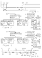
- Figure 1 is a diagram of the transmission of a main clock time as a function of time. The transmitted bits are not marked in the diagram but only the entire message.
- Figure 2 is a block diagram of the parts which must be present in the hardware which is coupled to the communication line in order to transmit a main clock time with high accuracy in time.
- Figure 3 is a block diagram of the parts which must be present in the hardware which is coupled to the communication line for receiving a main clock time with high accuracy in time.
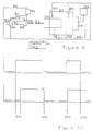
- Figure 4 is a diagram of the transmission of a main clock time as a function of time without the aid of special hardware.
- the transmitted bits are not marked in the diagram but only the entire messages which in reality frequently have a different or varying length.
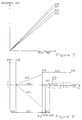
- Figure 5 describes how the clocks of the different units can diverge apart when they do not run accurately.
- Figure 6 describes how two clocks in the new arrangement diverge from the main clock's correct time and how they can be made to follow the main clock's time in an improved manner by setting and regulating these clocks.
- Figure 7 describes a setting-up of registers which can be used for obtaining at the receiver the information which is required for regulating the clocks in a correct manner.
- Figure 8 describes two units connected to a serial communication system and which are equipped in such a manner that the time message can be transmitted between the units.
- Figure 9 shows a control system in which the invention is used for simplifying and improving the system performance.
- Figure 10 shows how an event in time is distorted when it is transmitted with undeterminable and varying times to another unit.
- the circuit contains certain hardware for handling the clock. This is an attractive solution when the handling is simple since the clock is built into the communication circuit. The reason for this is that it has complete control over the communication and the times which apply in the transmission and which are listed in the text above.
- the hardware for the communication also has the functions which are required for obtaining transmission of serial messages according to any type of protocol.
- Figure 1 shows how the transmission of the time comes about.
- the communication circuit receives a start command at time (101) which says that a time message will be sent. Thereafter a certain delay (105) occurs which is based on the fact that the circuit must prepare itself for the transmission and it can also take further time if the communication line is occupied.
- the circuit When it has been determined that the time can be transmitted, the circuit reads the internal time and corrects this read time with the time (106) it takes to transmit the message.
- the time which is transmitted in the message is thus the time which will apply at the time marked by (103).
- the receiving circuit accepts the message and corrects the message with (107) before the clock can be set.
- This delay (107) is known in the design and the time read in which applies at (103) is corrected with this delay (107) before the clock is set at the time (104).
- the time (103) is a well-defined edge in the message which all can indicate accurately in time except for the delays which can occur in the electrical transmission. With this type of clock setting, the time can be set with a precision which is equivalent to or better than the time to transfer one bit in the communication system.
- Figure 2 shows the principle of construction of the communication circuit. This figure does not include all subblocks but only those which are most important to the description of the time function.
- There is a part (201) which ensures that data to be transmitted are taken from a buffer and are transmitted out over the communication channel (212) in a way which is correct for the protocol. This part also ensures that the data to be received are accepted and stored in a buffer. This unit will also check that the transmission takes place without errors and, when errors occur, will handle these in accordance with the communications specification.
- the transmit buffers are here marked by (202) and (203) and the receive buffers by (204) and (205), which can contain one or more words with data and commands. Naturally, there can be several such buffers depending on how many messages there are to be accepted and transmitted.
- the circuit can first transmit the one with the highest priority with the aid of priority. With one transmit and one receive buffer, with one or a few words, it is sufficient if the circuit can fetch and deliver data to some common memory via DMA (direct memory access) or another technique. However, this method makes it difficult to transmit several messages at the same time.
- the advantage of sending several messages at the same time is that no coordination is necessary if it is two. different subprograms which transmit two different messages. In the case of one buffer, it is necessary for a common program to be available which handles the communication and divides the communication buffer between different demands to transmit.
- the time message to be transmitted is fetched from a clock (207). Since it takes a certain time from when the time is transferred to when the time message reaches its receiver, the value in the clock must be corrected with a number (209) which is added in (208) to the value from the clock before the time is placed in the buffer (206).
- a clock time is obtained by calculating pulses from an oscillator (211) of some type (crystal).
- the pulses from the oscillator are corrected before they are transmitted to the clock. If the oscillator has too high a frequency, suitable pulses are extracted, and if it is too slow, extra pulses are transmitted to the clock. This regulating of the time is effected with the aid of electronics designated by (210). See separate item for regulating the clock.
- the circuit which transmits the time is almost identical with those which accept the time and that the distinction is created by adjusting the circuit in different ways with the aid of softwave and/or hardware. It is therefore possible to correct the clock rate by regulating the basic time, which is obtained from the oscillator, in the same way as in the receivers. This assumes that the 'master' is in some way coupled to an even better clock (the Telecommunications time signal). In this way, the main clock time can be given a high absolute accuracy.
- Transmission is effected in such a manner that the higher-order system indicates (101) to the transmitter that the time is to be transmitted. This can occur automatically after a certain adjustable or fixed time interval by means of equipment built into the hardware or through a signal from external equipment. It can also occur via a program in the computer unit which looks after the communication electronics, which by means of some algorithm can decide when a time transmission is appropriate.
- the transmission electronics (201) will then attempt to get through the communication system.
- the transmission electronics gives the instruction at (102) to cause the clock value to be stored in the buffer with the corrected value.
- This transfer is fast, one or a few clock pulses, so that the time required from when the command is given to when the data is located in the transmit buffer is not long. After this time, there must be no wait in the transmission; if a disturbance arises, the message must be terminated in such a manner that the partially transmitted information is not utilized by any receiver.
- the time data is to be transmitted, they can be fetched directly from the buffer and serially transmitted in the communication system.
- the clock can be directly updated with the transmitted time. If the time cannot be set directly at this instant, the transmitted time data must be corrected before it is placed at a new clock value. Normally, there is a slight delay (107) before the time read in is set to the clock since there is often some delay between the trigger edge and when the message is fully completed. By allowing the message to be completed, it is easier to check that there has not been any error in the information transferred. This checking is done by some type of check sum and/or by the receiver acknowledging that the message has been correctly received. When the time is set (104), the 'master clock' and the time written into the local clock coincide. The construction of the receiver can be almost identical to the transmit electronics.
- FIG 3 shows how it can be constructed and the only difference is that in this case the data will go from the buffer to the clock.
- the clock is set, the time obtained which corresponds to the time at (103) and which is located in register (308) will be added to the content in register (309) which corresponds to the time (107). The result will be that the clock (307) is set to time (104).
- the time it takes from when the unit receives the information about the new time until the clock is set.
- FIG. 4 shows how this type of time message is transferred in the communication system.
- the bits which are transferred have not been marked in the diagram, but the messages with the times (408), (409) and (410) and so forth have only been marked as a block. If the communications are free, the times (408) and (410) will be considerably shortened since these times are extended when other units are transmitting.
- the time information begins at time (401) and can be compared with (101) when the transmitting unit begins its transmitting phase. Here is shown directly one of the reasons why this must begin in good time before the time message itself.
- the locking message can be sent (409) if this message has the highest priority. This locking takes a certain time to be cleared by the receiving units, which is why there is a high risk that some other transmitter has been waiting to be admitted and has begun its transmission (410) before the locking has been detected. Before the message can be transmitted, it must be determined that the communication system is free before transmission starts, which is why a safety margin (411) is included. After that the transmitting frequency begins (405) with the readout of the clock, to this value will be added the times (412) and (413) which is the time taken to transfer the information to the receivers.
- the time (412) is based on the time it takes for the software to read out the clock, correct the time and place this data into the communication circuit.
- the time (412) is also based on the time it takes from when the communication circuit receives the transmit command until the message is output on the communication line. These times must be measured in the programming and the soft- and hardware must be such that this time (412) will be constant or with an ensured accuracy. The reason why all other communication must be stopped is that the communication system is free at time (412) yet nobody may begin to send. If somebody should begin to send, the time (412) could vary quite a lot.
- the information is transmitted to all receivers. A certain time (407) in the transmission is coupled to the time found in the message.
- the clocks of the units can be made to track one another more closely by regulating them. Regulation can be carried out, for example, in one of the following ways:
- Figure 5 shows how the time increases in different clocks in which an accurate clock (501) has also been provided as reference. If a better absolute time is desirable, the 'master' clock (502) can be regulated in such a manner that it tracks the correct absolute time (501) more closely.
- Figure 5 is transferred to Figure 6 where the difference from the main clock (502) is specified in the diagram. Considering the main clock (602), this will be correct when it is provided with a time error (600) of zero and therefore follows the zero line.
- the diagram begins at time (605) when all clocks are set for the first time. Before this time (610), the clocks can have any time whatever.
- the other clocks will deviate more and more from the time in the main clock. This deviation is mainly linear due to the stability of the oscillating circuits.
- the next time (606) when the 'master time' is transmitted the remaining units can calculate how much error the clocks have made since they have last been set. The units can use this calculated error to correct the rate (607, 608, 609) of the clocks in such a manner that they more closely track the time of the 'master clock'. To carry out this calculation, it is presupposed that two things are known.
- Figure 7 shows an example of a function block and register which can be used for obtaining the necessary information directly in the hardware. It is also possible to carry this out by means of software but this requires good knowledge of how long it takes to execute the necessary instructions. Uncertainty in these times will be directly apparent as misadjustment of the time. Compare with the transfer of the time. In the hardware it is possible to carry out the functions with high accuracy in time. After the second time message, a new time message can be produced less frequently since the error in the clock only occurs as a result of rounding errors and the non-linear part of the time error which is shown in the curves in Figure 6.
- Figure 7 shows the registers with clock data which are used for setting the time. In order to be able to utilize the information, it must be possible for most of these registers to be read by the higher-priority unit.
- the one marked by (701) is the register which holds the time transferred by means of the communication system, compare with (306) in Figure 3.
- the correction register (702) contains the value by which the transmitted time will be corrected.
- the value in the register is the difference between the time at the trigger point in the message and the time which applies when the internal clock (704) is set. When the clock is set, the value in (701) and (702) will be added to one another in the summing circuit (703) after which the result is used for setting the clock (704).
- this value is saved in register (706) and the one which was earlier located in (706) is transferred to (707). At that instant when the clock is set, the earlier clock value is transferred to a register (705). This is only one example of a configuration; naturally there are other ways of obtaining the necessary information.
- the first thing which is done in accordance with the invention is to obtain the time when the clock was set, which in this case is stored in (706). This is obtained by adding the content in (701) and (702) which occurs when the clock is set. To have something to refer to, this value is called 'CLOCKSET' (706). The value which was obtained at the preceding clock setting and which earlier was stored in (706) is transferred to the symbol (707). By taking the difference between (706) and (707), the time between clock settings can be obtained and this value is given the symbol name 'RUNTIME'. By subtracting the value in register (705) from the value in (706), 'CLOCKERR' is obtained which indicates how much the local clock has lost during the 'RUNTIME' time.
- Figure 8 describes two units coupled to the communication system, for example (904) and (908). These consist of a processor (801, 814), memory (802, 815), interface (803, 816, 821, 822), an oscillator (804, 813), serial communication circuit (805, 810) and an interface (807, 809) to the communication system (808).
- the unit (817) differs from (818) by having two oscillators (804, 806) coupled to the communication circuit, one being used for the clock and the other for keeping synchronism in reading-in and -out during communication.
- the unit (818) uses the oscillator (811) for serial communication. In this case, special hardware (812) coupled to the communication line is used for reading-in the clock.
- This method can be used when the unit (810) does not have any equipment for handling the clock and when full control of the clock setting is desired.
- the hardware (812) can also contain such electronics which support the software with times so that the setting of the clock can be effected with high precision in spite of the uncertainty of the software. It is possible to use an oscillator for all functions on the card.
- the units are equipped with inputs and outputs (819, 820) for coupling to the environment which the unit will control or read.
- unit (908) two communication units are connected. In this case, there must also be a setting-up of interface (807) and a communication circuit (805) in order to clear this channel.
- Figure 10 shows how the transmission of data with time information can improve the information transmitted.
- the upper curve shows how an event occurs in a unit and the lower one shows how this is reflected when it is received in the receiver.
- the receiving unit can calculate the delays DT1 - DT3 and compensate for these. For this to function, it is required that the clocks in all units give the same time with an error which is considerably less than the delays DT1 - DT3 which will be calculated.
- the system in Figure 9 consists of an hydraulic cylinder (912) which is controlled by the control unit (904) via the control valve (911).
- the position sensor (905) and pressure sensors (902, 903) are used for feedback. In this case, it is thought that the piston (913) of the hydraulic cylinder can be locked with the brake (906).
- the object (914) is heated in the furnace (915) which is controlled by the control unit (908) via a drive stage (916).
- Temperature sensors (907, 909) are coupled to the control unit (908) via communication line (910) and the sensors (917, 918) are connected via the communication system (919).
- a control panel (901) is also connected so that an operator can control the system. He can read the units or give new control commands via the communication line (910).
- All units connected to the communication channel have equipment to be able to transmit the information in accordance with the protocol applicable to the communication system.
- This equipment according to Figure 9 is used for positioning an object in a furnace.
- the cylinder (912) is also equipped with two pressure sensors (902, 903) besides the position sensor (905).
- a brake (906) In order to get the hydraulic cylinder to stand still, it is equipped with a brake (906).
- the control equipment (908) controls the output of the furnace so that the desired temperature can be obtained.
- the furnace regulator is provided via the communication system with information about the body's appearance and temperature of this unit so that a regulator can be optimized with respect to these particulars.
- Four temperature sensors (907, 908, 917, 918) are used for controlling the temperature. These sensors are arranged in such a manner that they only send the temperature values when the temperature changes by a preset value. In this manner there is no unnecessary information transfer.
- To control the temperature in a furnace is a relatively slow process which means that the temperature transmissions can occur at long intervals.
- the problem in regulating a furnace consists in taking into consideration the delay times which apply in the system. By analysing the system, a model can be created which can then be used for obtaining good regulation of the furnace output. For this regulation to function well, the correct input data must be obtained, that is to say the temperature read and its position in time must be accurate and the weight, appearance and heat capacity of the body introduced in the furnace must be well determined.
- the positioning is not continuous, but the positioning is effected over a short time after which the position is locked with (906).
- the positioning will be carried out with high accuracy which means that large amounts of information must be transferred from the sensors (902, 903, 905) which are used in the positioning.
- These pressure and position data therefore have high priority. It is here assumed that this volume of information is so large that it locks up the entire communication system, that is to say the furnace cannot obtain any temperature data during positioning. However, this does not matter since the positioning occurs within such a short time that the temperature data is not unnecessarily delayed. However, variation in the delay can produce a problem in the modelling since the temperature data does not keep adequate accuracy in time. In this system where there is a common time in the system, the temperature is followed by a time information which which means that the control unit can place the temperature data correctly in time. By this means, a correct calculation can be carried out and good temperature control obtained.
- the system had not had a common clock, it would have been necessary to introduce two different communication loops, one for the furnace and one for the positioning. It would also have been necessary to equip the system with a further communication system for coupling the two adjusting units to the common higher-priority control unit. This would also require a communication port in the adjusting units. It would also be necessary for the position regulator to transfer position data to the furnace control via the second communication line, which data in our case could be obtained only by reading the data traffic from the position sensor to the position control.
Abstract
Description
- 1
- Reducing or adding pulses from the oscillator with one or several different intervals.
- 2
- Adding one or different numbers directly to the clock with different intervals.
- 3
- Adding a precalculated number to the clock by means of a special program with certain intervals.
Claims (6)
- Arrangement for correction of one or more clocks (207,307) in a machinery and/or processing system which arrangement comprises a serial data communication channel (808) and two or more units (817,818) connected to the channel; one of said units comprises a main clock (207) and the other unit or units each comprises a local clock (307); the unit (817) including the main clock is adapted to provide, via the channel (808), transmission of the time information of the main clock to the other unit (818) or units, so as to synchronize the local clocks with the transmitted main clock time information; and each unit comprises an oscillator (211, 311) which outputs to the respective clock a pulse train having a fundamental frequency, characterised in that at least one of said units is provided with an adjustment device (208, 209, 210; 308, 309, 310) which adjusts the pulse train emitted from the oscillator in dependence of the main clock time information, so that the respective local clock provides a closer tracking of the time of the main clock between the transmitted time information.
- Arrangement according to claim 1, characterised in that the adjustment device includes a member (210, 310) which generates a number of pulses which can be added to said pulse train in a register device (208, 308).
- Arrangement according to claim 1 or 2, characterised in that the adjustment device includes a regulator (210, 310) which affects the pulse train emitted from the oscillator by means of addition or removal of pulses to or from the puls train.
- Arrangement according to claims 1-3, characterised in that the determination of the time by one of the local clocks is executed by means of two main clock time informations transmitted from the unit including the main clock.
- Arrangement according to claim 1, 2 or 3, characterised in that the time adjustment is provided by means of software.
- Arrangement in a machinery and/or processing system, which arrangement comprises a common serial data communication channel and two or more collaborating units which exchanges messages and which get access to the channel by priority procedures, in which a message having higher priority gets access to the channel over a message having lower priority; each unit having a communication circuit (805, 810) and being connected to the channel via its communication circuit; an appointed message is transferred between the units alter the transmission of a preceding message which prohibits the other unit or all other units to effect communication on the channel, or alternatively when the appointed message gets access by means of said priority procedure; each of said units is arranged to provide data associated with events or produces events associated with data; said data are included in messages which are to be transferred on the channel, a clock arrangement is adapted to determine the time when said data occur/take places independent of the priorities of the data messages between the units; said clock arrangement includes clock adapted in said units; a clock included in a first unit operates as a main clock; the time information of the main clock, or a reference to this time information, is transferred via the channel from the first unit by means of said appointed message, which represents a time message, which is transmitted intermixed with messages which do not include time information; said clocks are adapted for co-ordination in relation to each other and the clock in each unit can be set with adjustable accuracy, in dependence of the main clock information, so that the respective local clock provides a closer tracking of the time of the main clock between the transmitted time information.
Applications Claiming Priority (3)
| Application Number | Priority Date | Filing Date | Title |
|---|---|---|---|
| SE8901495 | 1989-04-25 | ||
| SE8901495A SE466123B (en) | 1989-04-25 | 1989-04-25 | DEVICE FOR SYNCONIZING DATA IN A COMPUTER SYSTEM INCLUDING A COMMON SERIAL DATA COMMUNICATION CHANNEL |
| PCT/SE1990/000264 WO1990013078A1 (en) | 1989-04-25 | 1990-04-20 | Arrangement in a computer system |
Publications (2)
| Publication Number | Publication Date |
|---|---|
| EP0470199A1 EP0470199A1 (en) | 1992-02-12 |
| EP0470199B1 true EP0470199B1 (en) | 1998-07-08 |
Family
ID=20375782
Family Applications (1)
| Application Number | Title | Priority Date | Filing Date |
|---|---|---|---|
| EP90908115A Expired - Lifetime EP0470199B1 (en) | 1989-04-25 | 1990-04-20 | Clock synchronisation in a computer system |
Country Status (7)
| Country | Link |
|---|---|
| US (1) | US5392421A (en) |
| EP (1) | EP0470199B1 (en) |
| JP (1) | JP3091482B2 (en) |
| KR (1) | KR920701895A (en) |
| DE (1) | DE69032468T2 (en) |
| SE (1) | SE466123B (en) |
| WO (1) | WO1990013078A1 (en) |
Cited By (1)
| Publication number | Priority date | Publication date | Assignee | Title |
|---|---|---|---|---|
| DE10191695B4 (en) * | 2000-05-04 | 2009-07-23 | Fts Computertechnik Ges.M.B.H. | Method and communication control unit for multimaster clock synchronization in a distributed real-time computer system |
Families Citing this family (42)
| Publication number | Priority date | Publication date | Assignee | Title |
|---|---|---|---|---|
| US5922602A (en) | 1988-02-26 | 1999-07-13 | Biosource Technologies, Inc. | Cytoplasmic inhibition of gene expression |
| DE4140017C2 (en) * | 1991-12-04 | 1995-01-05 | Nec Electronics Germany | Method for operating computer units communicating with one another via a data bus by serial data exchange |
| US5537549A (en) * | 1993-04-28 | 1996-07-16 | Allen-Bradley Company, Inc. | Communication network with time coordinated station activity by time slot and periodic interval number |
| JP3203939B2 (en) * | 1994-02-28 | 2001-09-04 | 富士ゼロックス株式会社 | Drawing communication device |
| US5898864A (en) * | 1995-09-25 | 1999-04-27 | International Business Machines Corporation | Method and system for executing a context-altering instruction without performing a context-synchronization operation within high-performance processors |
| US5748941A (en) * | 1995-11-09 | 1998-05-05 | Xerox Corporation | System and method for synchronizing control clocks for a modular printing system |
| US5805870A (en) * | 1996-06-28 | 1998-09-08 | International Business Machines Corporation | System and method for correcting clock drift in multiprocessor systems |
| US5805088A (en) * | 1996-11-01 | 1998-09-08 | International Business Machines Corporation | High speed asynchronous serial to parallel data converter |
| DE19722114C2 (en) * | 1997-05-27 | 2003-04-30 | Bosch Gmbh Robert | Clock signal providing device and method |
| US6278710B1 (en) * | 1998-09-10 | 2001-08-21 | Agilent Technologies, Inc. | Enhancements to time synchronization in distributed systems |
| US6092210A (en) * | 1998-10-14 | 2000-07-18 | Cypress Semiconductor Corp. | Device and method for synchronizing the clocks of interconnected universal serial buses |
| US6105097A (en) * | 1998-10-14 | 2000-08-15 | Cypress Semiconductor Corp. | Device and method for interconnecting universal serial buses including power management |
| US6311294B1 (en) | 1998-10-20 | 2001-10-30 | Cypress Semiconductor Corp. | Device and method for efficient bulk data retrieval using a universal serial bus |
| US6389495B1 (en) | 1999-01-16 | 2002-05-14 | Cypress Semiconductor Corp. | Dedicated circuit and method for enumerating and operating a peripheral device on a universal serial bus |
| US6728880B1 (en) * | 1999-09-17 | 2004-04-27 | Adobe Systems Incorporated | Secure time on computers with insecure clocks |
| CN1290278C (en) * | 2001-07-18 | 2006-12-13 | 松下电器产业株式会社 | Data transmission apparatus and data transmission method |
| JP2003196166A (en) * | 2001-10-19 | 2003-07-11 | Kawasaki Microelectronics Kk | Data transfer device |
| SE528607C2 (en) * | 2004-04-30 | 2006-12-27 | Kvaser Consultant Ab | System and device for temporarily relating events in a vehicle |
| SE0401922L (en) * | 2004-07-23 | 2005-05-31 | Kvaser Consultant Ab | Device for time stamping of reference events |
| US7649912B2 (en) * | 2005-04-27 | 2010-01-19 | Rockwell Automation Technologies, Inc. | Time synchronization, deterministic data delivery and redundancy for cascaded nodes on full duplex ethernet networks |
| FI119205B (en) * | 2005-06-29 | 2008-08-29 | Abb Oy | Time synchronization |
| US7636345B2 (en) * | 2006-02-01 | 2009-12-22 | Comsys Communication & Signal Processing Ltd. | Apparatus for and method of time related communications between multiple devices having different time bases |
| US8315269B1 (en) | 2007-04-18 | 2012-11-20 | Cypress Semiconductor Corporation | Device, method, and protocol for data transfer between host device and device having storage interface |
| US7859240B1 (en) | 2007-05-22 | 2010-12-28 | Cypress Semiconductor Corporation | Circuit and method for preventing reverse current flow into a voltage regulator from an output thereof |
| TWI448902B (en) * | 2007-08-24 | 2014-08-11 | Cypress Semiconductor Corp | Bridge device with page-access based processor interface |
| US8090894B1 (en) | 2007-09-21 | 2012-01-03 | Cypress Semiconductor Corporation | Architectures for supporting communication and access between multiple host devices and one or more common functions |
| US7895387B1 (en) | 2007-09-27 | 2011-02-22 | Cypress Semiconductor Corporation | Devices and methods for sharing common target device with two different hosts according to common communication protocol |
| US8370675B2 (en) * | 2009-01-28 | 2013-02-05 | Mellanox Technologies Ltd. | Precise clock synchronization |
| DE102009037156A1 (en) * | 2009-08-04 | 2011-02-17 | Lenze Automation Gmbh | Method for the synchronous recording and recording of process and / or status data and automation system |
| US11483127B2 (en) | 2018-11-18 | 2022-10-25 | Mellanox Technologies, Ltd. | Clock synchronization |
| US11283454B2 (en) | 2018-11-26 | 2022-03-22 | Mellanox Technologies, Ltd. | Synthesized clock synchronization between network devices |
| US10778406B2 (en) | 2018-11-26 | 2020-09-15 | Mellanox Technologies, Ltd. | Synthesized clock synchronization between networks devices |
| US11543852B2 (en) | 2019-11-07 | 2023-01-03 | Mellanox Technologies, Ltd. | Multihost clock synchronization |
| EP3820105B1 (en) * | 2019-11-11 | 2023-03-15 | Siemens Aktiengesellschaft | Method and system for secure time synchronization |
| US11070304B1 (en) | 2020-02-25 | 2021-07-20 | Mellanox Technologies, Ltd. | Physical hardware clock chaining |
| US11552871B2 (en) | 2020-06-14 | 2023-01-10 | Mellanox Technologies, Ltd. | Receive-side timestamp accuracy |
| US11606427B2 (en) | 2020-12-14 | 2023-03-14 | Mellanox Technologies, Ltd. | Software-controlled clock synchronization of network devices |
| US11588609B2 (en) | 2021-01-14 | 2023-02-21 | Mellanox Technologies, Ltd. | Hardware clock with built-in accuracy check |
| US11907754B2 (en) | 2021-12-14 | 2024-02-20 | Mellanox Technologies, Ltd. | System to trigger time-dependent action |
| US11835999B2 (en) | 2022-01-18 | 2023-12-05 | Mellanox Technologies, Ltd. | Controller which adjusts clock frequency based on received symbol rate |
| US11706014B1 (en) | 2022-01-20 | 2023-07-18 | Mellanox Technologies, Ltd. | Clock synchronization loop |
| US11917045B2 (en) | 2022-07-24 | 2024-02-27 | Mellanox Technologies, Ltd. | Scalable synchronization of network devices |
Citations (3)
| Publication number | Priority date | Publication date | Assignee | Title |
|---|---|---|---|---|
| US4337463A (en) * | 1980-08-22 | 1982-06-29 | Control Data Corporation | Time synchronization master station and remote station system |
| EP0247026A2 (en) * | 1986-05-16 | 1987-11-25 | Austria Mikrosysteme International Gmbh | Method for synchronizing the time clocks of computing devices connected to a communication medium, and the computing devices concerned |
| US4750194A (en) * | 1987-03-05 | 1988-06-07 | United States Pipe And Foundry Company | Clock synchronization system |
Family Cites Families (4)
| Publication number | Priority date | Publication date | Assignee | Title |
|---|---|---|---|---|
| US3577128A (en) * | 1969-01-14 | 1971-05-04 | Ibm | Synchronizing clock system |
| GB2127594B (en) * | 1982-09-18 | 1985-11-13 | Int Computers Ltd | Distribution of clock pulses |
| US4584643A (en) * | 1983-08-31 | 1986-04-22 | International Business Machines Corporation | Decentralized synchronization of clocks |
| US4890222A (en) * | 1984-12-17 | 1989-12-26 | Honeywell Inc. | Apparatus for substantially syncronizing the timing subsystems of the physical modules of a local area network |
-
1989
- 1989-04-25 SE SE8901495A patent/SE466123B/en not_active IP Right Cessation
-
1990
- 1990-04-20 EP EP90908115A patent/EP0470199B1/en not_active Expired - Lifetime
- 1990-04-20 KR KR1019910701433A patent/KR920701895A/en not_active Application Discontinuation
- 1990-04-20 JP JP02507221A patent/JP3091482B2/en not_active Expired - Lifetime
- 1990-04-20 WO PCT/SE1990/000264 patent/WO1990013078A1/en active IP Right Grant
- 1990-04-20 DE DE69032468T patent/DE69032468T2/en not_active Expired - Lifetime
- 1990-04-20 US US07/773,876 patent/US5392421A/en not_active Expired - Lifetime
Patent Citations (3)
| Publication number | Priority date | Publication date | Assignee | Title |
|---|---|---|---|---|
| US4337463A (en) * | 1980-08-22 | 1982-06-29 | Control Data Corporation | Time synchronization master station and remote station system |
| EP0247026A2 (en) * | 1986-05-16 | 1987-11-25 | Austria Mikrosysteme International Gmbh | Method for synchronizing the time clocks of computing devices connected to a communication medium, and the computing devices concerned |
| US4750194A (en) * | 1987-03-05 | 1988-06-07 | United States Pipe And Foundry Company | Clock synchronization system |
Cited By (1)
| Publication number | Priority date | Publication date | Assignee | Title |
|---|---|---|---|---|
| DE10191695B4 (en) * | 2000-05-04 | 2009-07-23 | Fts Computertechnik Ges.M.B.H. | Method and communication control unit for multimaster clock synchronization in a distributed real-time computer system |
Also Published As
| Publication number | Publication date |
|---|---|
| US5392421A (en) | 1995-02-21 |
| EP0470199A1 (en) | 1992-02-12 |
| SE8901495D0 (en) | 1989-04-25 |
| JPH04507157A (en) | 1992-12-10 |
| SE8901495L (en) | 1990-10-26 |
| DE69032468D1 (en) | 1998-08-13 |
| JP3091482B2 (en) | 2000-09-25 |
| SE466123B (en) | 1991-12-16 |
| KR920701895A (en) | 1992-08-12 |
| WO1990013078A1 (en) | 1990-11-01 |
| DE69032468T2 (en) | 1999-01-07 |
Similar Documents
| Publication | Publication Date | Title |
|---|---|---|
| EP0470199B1 (en) | Clock synchronisation in a computer system | |
| US7058089B2 (en) | System and method for maintaining a common sense of time on a network segment | |
| US6535926B1 (en) | Time synchronization system for industrial control network using global reference pulses | |
| US4803682A (en) | Resetting system | |
| US5483201A (en) | Synchronization circuit using a high speed digital slip counter | |
| JPH10503282A (en) | Controlled time scale generator for use as primary reference clock | |
| JPH0715421A (en) | Clock synchronizing device in communication network | |
| US4575848A (en) | Methods and apparatus for correcting a software clock from an accurate clock | |
| US11310026B2 (en) | Communication system, communication device, and program | |
| Volz et al. | Timing issues in the distributed execution of Ada programs | |
| US7249272B1 (en) | Apparatus and method for coordinating activities of one or more computers | |
| EP0187310B1 (en) | Real time clock synchronization | |
| CN102668378A (en) | Information processing apparatus or information processing method | |
| JPH02285215A (en) | Method and equipment for controlling measuring system | |
| US6701836B2 (en) | Printing-machine drive system | |
| US5634041A (en) | Rationally clocked communication interface | |
| EP1053619A1 (en) | System and method for generating a real-time signal | |
| EP3814868B1 (en) | Precision timing between systems | |
| JP7333705B2 (en) | circuit system | |
| JPH06282504A (en) | Time control system | |
| JPH0325518A (en) | Time synchronizing system | |
| JPH0435096B2 (en) | ||
| US20090210926A1 (en) | method for maintaining plesiochronous entities | |
| US20040190664A1 (en) | System and method for time-marking data | |
| JPH04253212A (en) | Remote time setting system |
Legal Events
| Date | Code | Title | Description |
|---|---|---|---|
| PUAI | Public reference made under article 153(3) epc to a published international application that has entered the european phase |
Free format text: ORIGINAL CODE: 0009012 |
|
| 17P | Request for examination filed |
Effective date: 19911009 |
|
| AK | Designated contracting states |
Kind code of ref document: A1 Designated state(s): BE CH DE FR GB LI |
|
| 17Q | First examination report despatched |
Effective date: 19950707 |
|
| GRAG | Despatch of communication of intention to grant |
Free format text: ORIGINAL CODE: EPIDOS AGRA |
|
| GRAG | Despatch of communication of intention to grant |
Free format text: ORIGINAL CODE: EPIDOS AGRA |
|
| GRAH | Despatch of communication of intention to grant a patent |
Free format text: ORIGINAL CODE: EPIDOS IGRA |
|
| GRAH | Despatch of communication of intention to grant a patent |
Free format text: ORIGINAL CODE: EPIDOS IGRA |
|
| GRAA | (expected) grant |
Free format text: ORIGINAL CODE: 0009210 |
|
| AK | Designated contracting states |
Kind code of ref document: B1 Designated state(s): BE CH DE FR GB LI |
|
| REG | Reference to a national code |
Ref country code: CH Ref legal event code: EP |
|
| REF | Corresponds to: |
Ref document number: 69032468 Country of ref document: DE Date of ref document: 19980813 |
|
| ET | Fr: translation filed | ||
| REG | Reference to a national code |
Ref country code: CH Ref legal event code: NV Representative=s name: ISLER & PEDRAZZINI AG |
|
| PLBE | No opposition filed within time limit |
Free format text: ORIGINAL CODE: 0009261 |
|
| STAA | Information on the status of an ep patent application or granted ep patent |
Free format text: STATUS: NO OPPOSITION FILED WITHIN TIME LIMIT |
|
| 26N | No opposition filed | ||
| REG | Reference to a national code |
Ref country code: GB Ref legal event code: IF02 |
|
| REG | Reference to a national code |
Ref country code: CH Ref legal event code: PCAR Free format text: ISLER & PEDRAZZINI AG;POSTFACH 1772;8027 ZUERICH (CH) |
|
| PGFP | Annual fee paid to national office [announced via postgrant information from national office to epo] |
Ref country code: BE Payment date: 20080616 Year of fee payment: 19 |
|
| REG | Reference to a national code |
Ref country code: CH Ref legal event code: PFA Owner name: TIMEGALACTIC AB Free format text: KVASER CONSULTANT AB#BERGGRAEND 1 P.O. BOX 4076#S-511 04 KINNA (SE) -TRANSFER TO- TIMEGALACTIC AB#BOX 4#51127 KINNA (SE) |
|
| REG | Reference to a national code |
Ref country code: FR Ref legal event code: CD Ref country code: FR Ref legal event code: CA |
|
| PGFP | Annual fee paid to national office [announced via postgrant information from national office to epo] |
Ref country code: GB Payment date: 20090320 Year of fee payment: 20 |
|
| PGFP | Annual fee paid to national office [announced via postgrant information from national office to epo] |
Ref country code: DE Payment date: 20090430 Year of fee payment: 20 |
|
| PGFP | Annual fee paid to national office [announced via postgrant information from national office to epo] |
Ref country code: CH Payment date: 20090505 Year of fee payment: 20 |
|
| BERE | Be: lapsed |
Owner name: TIMEGALACTIC A.B. Effective date: 20090430 |
|
| REG | Reference to a national code |
Ref country code: GB Ref legal event code: 732E Free format text: REGISTERED BETWEEN 20091015 AND 20091021 |
|
| REG | Reference to a national code |
Ref country code: FR Ref legal event code: ST Effective date: 20091231 |
|
| PG25 | Lapsed in a contracting state [announced via postgrant information from national office to epo] |
Ref country code: FR Free format text: LAPSE BECAUSE OF NON-PAYMENT OF DUE FEES Effective date: 20091222 |
|
| PGFP | Annual fee paid to national office [announced via postgrant information from national office to epo] |
Ref country code: FR Payment date: 20080422 Year of fee payment: 19 |
|
| REG | Reference to a national code |
Ref country code: CH Ref legal event code: PL |
|
| REG | Reference to a national code |
Ref country code: GB Ref legal event code: PE20 Expiry date: 20100419 |
|
| PG25 | Lapsed in a contracting state [announced via postgrant information from national office to epo] |
Ref country code: BE Free format text: LAPSE BECAUSE OF NON-PAYMENT OF DUE FEES Effective date: 20090430 |
|
| PG25 | Lapsed in a contracting state [announced via postgrant information from national office to epo] |
Ref country code: GB Free format text: LAPSE BECAUSE OF EXPIRATION OF PROTECTION Effective date: 20100419 |
|
| PG25 | Lapsed in a contracting state [announced via postgrant information from national office to epo] |
Ref country code: DE Free format text: LAPSE BECAUSE OF EXPIRATION OF PROTECTION Effective date: 20100420 |