EP0465192A1 - Electronic sphygmomanometer - Google Patents
Electronic sphygmomanometer Download PDFInfo
- Publication number
- EP0465192A1 EP0465192A1 EP91305952A EP91305952A EP0465192A1 EP 0465192 A1 EP0465192 A1 EP 0465192A1 EP 91305952 A EP91305952 A EP 91305952A EP 91305952 A EP91305952 A EP 91305952A EP 0465192 A1 EP0465192 A1 EP 0465192A1
- Authority
- EP
- European Patent Office
- Prior art keywords
- air
- bleed valve
- pressure
- constant rate
- electronic sphygmomanometer
- Prior art date
- Legal status (The legal status is an assumption and is not a legal conclusion. Google has not performed a legal analysis and makes no representation as to the accuracy of the status listed.)
- Granted
Links
Images

Classifications
-
- A—HUMAN NECESSITIES
- A61—MEDICAL OR VETERINARY SCIENCE; HYGIENE
- A61B—DIAGNOSIS; SURGERY; IDENTIFICATION
- A61B5/00—Measuring for diagnostic purposes; Identification of persons
- A61B5/02—Detecting, measuring or recording pulse, heart rate, blood pressure or blood flow; Combined pulse/heart-rate/blood pressure determination; Evaluating a cardiovascular condition not otherwise provided for, e.g. using combinations of techniques provided for in this group with electrocardiography or electroauscultation; Heart catheters for measuring blood pressure
- A61B5/021—Measuring pressure in heart or blood vessels
- A61B5/022—Measuring pressure in heart or blood vessels by applying pressure to close blood vessels, e.g. against the skin; Ophthalmodynamometers
- A61B5/0235—Valves specially adapted therefor
Abstract
an electric pump (26) driven by a battery (34);
a pressure sensor for detecting a pulse and the air pressure inside a cuff which is pressurized by the electric pump;
a constant rate air-bleed valve (5) for reducing the pressure in the cuff at a constant rate; and
a display device (33) for displaying the systolic and diastolic blood pressure values of a patient whose blood pressure is being measured, these values being calculated based on the air pressure and the pulse which is detected;
wherein the constant rate air-bleed valve (27c) comprises:
an air-bleed valve casing (5) of which one end is joined to an air pipe (20) connected to the cuff (19) and the other end is open to atmosphere;
a tubular member (10) formed from an elastic member positioned in the air-bleed valve casing so that one end, which is provided with a slit (11) is closed while the other end is open to atmosphere, and the one end of the tubular members extends up to the side end of the air-bleed valve casing; and
a regulating member (6) which is set to press against the outer peripheral surface close to one end of the tubular member and can be regulated from the outside of the air-bleed valve casing.
Description
- The present invention relates to an electronic sphygmomanometer, and, in particular, to a constant rate air-bleed adjustment device for a sphygmomanometer whereby the pressure in a cuff can be easily adjusted to drop at a substantially uni form rate.
- Conventional electronic sphygmomanometers wherein a cuff is pressurized by means of a battery-driven electric pump, a pulse and the air pressure inside the cuff are detected by a pressure sensor, and the systolic and diastolic blood pressure values of a patient whose blood pressure is being measured are obtained and displayed on a digital display device are in widespread use.
- In this type of electronic sphygmomanometer, a constant rate air-bleed device is used in order to reduce the pressure of the air inside the cuff at a constant rate.
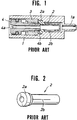
- FIG. 1 shows one example of a constant rate air-bleed valve used with a conventional electronic sphygmomanometer.
- In this constant rate air-bleed valve, a
flange section 2a of atubular member 2, as shown in FIG.2, is insertedly pressed into an inner section of an air-bleed valve casing 1 with a pressure side port 1a by means of anut 3, and, in addition. a regulating member 4 is screwed into the nut 3 (as, for example, in Japanese Patent Publication 63-14809). - The
flange section 2a is provided on one end of thetubular member 2, as shown in FIG.2, and on the outer peripheral side surface of thetubular member 2, aslit 2b is provided, extending in the longitudinal direction from theflange section 2a. An air-bleed hole 4a is formed in the center of the regulating member 4, and anend 4b of the regulating member 4 contacts theflange section 2a of thetubular member 2. The rate of pressure reduction is regulated by screwing in the regulating member 4, thus increasing the pressure on the thetubular member 2 in the thrust direction, so that the amount of open area of thelongitudinal slit 2b increases, corresponding to this pressure. - Accordingly, in this type of conventional constant-rate air-bleed valve, because the
longitudinal slit 2a is provided in thetubular member 2, a uniform length in the longitudinal direction is absolutely necessary to obtain good characteristics. In addition, because pressure must be added in the thrust direction, the length of the regulating section in the longitudinal direction must be great. Also, to ensure that the regulating section is airtight, the regulating section must also be large in the radial direction. This gives rise to the drawback that the overall air-bleed valve must be large. - An object of the present invention is to provide, with due consideration to the drawbacks of such conventional devices, a small-sized, high-performance electronic sphygmomanometer wherein the rate of drop of the air pressure can be easily adjusted as a result of improvements to the air bleed valve so that blood pressure can be precisely measured with a minimum of error.
- the object of the present invention is achieved by the provision of an electronic sphygmomanometer with a configuration wherein, in the air piping system, an open end of a tubular member, which is the main body of an air-bleed valve, is positioned on the low pressure side; the other end, which is a closed end, is positioned on the high pressure side, specifically, the airflow intake end during air bleed; and this other end is provided with a radial slit at the closed end of the tubular member which is formed from an elastic member, and the slit is caused to open by an adjustment member which applies pressure to the cylindrical surface of the tubular member.
- In this configuration, when the pressure in the cuff is high during the measurement of the blood pressure, the slit opening in the tubular member remains narrow because of the backpressure applied by the adjustment member. When the pressure in the cuff drops, the opening widens in proportion to this drop because the cylindrical member returns to its original shape. Specifically, it is possible to maintain a constant rate of pressure drop by a minute change in the area of the opening in the slit. In addition, the shape of the tubular member and its hardness and elasticity are determined during the design process so that the rate of pressure drop can be controlled by setting the amount of opening in the slit with the adjustment member.
- These and other objects, features, and advantages of the present invention will become more apparent from the following description of the preferred embodiments taken in conjunction with the accompanying drawings, in which:
- FIG. 1 is a sectional view of a constant rate air-bleed valve used with a conventional electronic sphygmomanometer.
- FIG.2 is a perspective view of a tubular member incorporating the constant rate airbleed valve shown in FIG. 1.
- FIG.3 is a perspective view showing the conditions of use of the electronic sphygmomanometer of the present invention.
- FIG.4 is a perspective view showing the electronic sphygmomanometer of the present invention with the upper casing removed.
- FIG.5 is an end elevation of a pressure pump for the electronic sphygmomanometer of the present invention.
- FIG.6 is a sectional view of one embodiment of the constant rate air-bleed valve used with the electronic sphygmomanometer of the present invention.
- FIG.7 is a perspective view of a tubular member incorporating the constant rate air-bleed valve shown in FIG. 6.
- The present invention will now be explained with reference to the drawings.
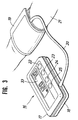
- FIG.3 shows the conditions of use of the electronic sphygmomanometer of the present invention.
- An
electronic sphygmomanometer 16 comprises a main body, made up of anupper casing 17 and alower casing 18, and acuff 19 to be applied to anarm 21, the main body and thecuff 19 being joined through arubber tube 20. A liquidcrystal display device 33 for displaying the blood pressure of patient being examined and the initially set pressurization value is provided on the surface of theupper casing 17 together with apower switch 22, ameasurement switch 23 for starting the measurement, amemory switch 24 for storing the measured blood pressure values in memory, and an initial pressurization value setswitch 25 for optionally setting the initial pressurization value at the cuff. - Next, the internal configuration of the
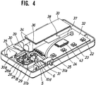
electronic sphygmomanometer 16 will be explained based on FIG.4. FIG.4 shows the state of theelectronic sphygmomanometer 16 with theupper casing 17 and therubber tube 20 removed. The main components of the internal section of theelectronic sphygmomanometer 16 are apressure pump 2b, amagnetic valve 31, acircuit substrate 32, the liquidcrystal display device 33, and abattery housing chamber 34. - The
pressure pump 26 as shown in FIG.5 is a diaphragm compressor which is provided with adiaphragm 27 fabricated from nitrile butadiene rubber (hereinafter NBR). The center section of thediaphragm 27 has amounting section 27a provided with ashaft 39. In addition, an air intake valve 27b and an air-bleedvalve 27c are provided on the outer peripheral section of thediaphragm 27, and the inner peripheral sections of the air intake valve 27b and the air-bleedvalve 27c are interposedly secured between anupper pump casing 28 and alower pump casing 29. - The
upper pump casing 28 is provided with anair intake port 28a and an air-bleed port 28b respectively positioned opposite the air intake valve 27b and the air-bleedvalve 27c of thediaphragm 27. Theupper pump casing 28 is integrally formed with a later-described air-bleedvalve casing 5. Achamber 40 is formed between thediaphragm 27 and thelower pump casing 29, and apacking 42 is provided to hermetically seal theupper pump casing 28 and thelower pump casing 29. - A
motor 30 is provided to activate thediaphragm 27 in the vertical direction. Theshaft 39 provided on themounting section 27a of thediaphragm 27 is eccentrically mounted on ashaft 30a of themotor 30. - A
channel 41 communicates with the air-bleedport 28b and is connected to a pressure side port of a later-described constant rate air bleedvalve 27c for the sphygmomanometer. - A
rubber tube 36 is provided for introducing the air exiting from the air-bleedport 28b to a pressurizingport 31a of themagnetic valve 31. Therubber tube 20 is connected to the pressurizingport 31a of themagnetic valve 31, and feeds the air into thecuff 19. One end of arubber tube 37 is connected to themagnetic valve 31 and communicates with the pressurizingport 31a. The other end of therubber tube 37 is connected to a pressure sensor (omitted from the drawings) mounted on thecircuit board 32. Themagnetic valve 31 is also provided with an air-bleed port 31b, and when the blood pressure measurement is completed themagnetic valve 31 opens to allow the air in thecuff 19 to bleed out through the air-bleed port 31b. - In addition to the pressure sensor (omitted from the drawings), the
power switch 22, themeasurement switch 23, thememory switch 24, and the initial pressurizationvalue set switch 25 are positioned on anIC chip 43, together with a necessary wiring system for supplying power and signals to the pressurizingpump 26. - The liquid
crystal display device 33, which displays the blood pressure values and the like, is connected to thecircuit substrate 32 through aflat cable 38. - The
battery housing chamber 34, which is integrally formed with thelower casing 18, houses a battery (omitted from the drawings). - FIG.6 is a sectional view of one embodiment of the constant rate air-bleed valve used with the electronic sphygmomanometer of the present invention.
- A
tubular member 10 which is illustrated in FIG.7 is positioned inside an air-bleedvalve casing 5. One end of thetubular member 10 is open, and the other end is formed as an elastic member fabricated from rubber (such as, for example, silicone rubber or NBR, of a spring-type hardness of 60°) and is closed. Thetubular member 10 comprises alarge diameter section 10a, amedium diameter section 10b, and asmall diameter section 10c, the diameters of all these sections being different. Afine slit 11 is formed in the radial direction in thesmall diameter section 10c of thetubular member 10, which is the same direction as the forward movement of a later-described adjustingmember 6. Thelarge diameter section 10a of thetubular member 10 is engaged by a mediumdiameter diameter section 5a of the air-bleedvalve casing 5 while ensuring air tightness. - The air-bleed
valve casing 5 is shaped as a hollow tube. Aprojection 5b for housing a regulatingmember 6 is provided on the surface of the cylinder. Anut 7 is embeddedly secured in theprojection 5b, and the regulatingmember 6 can be screwed into thenut 7 causing the regulatingmember 6 to advance. Atip 6a of the regulatingmember 6 penetrates through a small hole 5c in the side surface of the air-bleed valve casing 5, and thetip 6a is formed so that it presses against an outer peripheral surface 8 of thetubular member 10. When the regulatingmember 6 is screwed into thenut 7, an opening is formed in theslit 11 proportional to the amount by which the regulatingmember 6 is screwed in. An O-ring 9 is provided on the head of the regulatingmember 6 to ensure the airtightness of the regulatingmember 6. In the air-bleed regulating device of this configuration, the air piping system of the sphygmomanometer has anopen end 10d on the low pressure side and apressure side port 5d on the high pressure side. - As shown in FIG.4, the constant rate air-bleed valve is positioned in the
lower casing 18 so that the longitudinal direction of thetubular member 10 becomes the lateral direction of the constant rate air-bleed valve, and theprojection 5b, which is the regulating part, is positioned facing upward so that regulation from the top is possible. - The operation of the electronic sphygmomanometer of the present invention will now be explained.
- To use the electronic sphygmomanometer, the
cuff 19 is first wrapped around the upper arm of the patient whose blood pressure is to be measured and the power switch is turned ON. - Next, the initial pressurization value set
switch 25 is pressed, and the initial pressurization value is optionally selected. In this embodiment of the present invention, the liquidcrystal display device 33 shown in FIG.3 is set for 160 mm Hg. - The
pressurization pump 26 is then started by pressing themeasurement switch 23. Specifically, thediaphragm 27 is activated vertically through the rotation of theshaft 30a of themotor 30 so that when thediaphragm 27 moves upward, the air intake valve 27b opens and air is drawn into thechamber 40 through theair intake port 28a, and when thediaphragm 27 moves downward, the air-bleed valve 27c opens and air is discharged from thechamber 40 through the air-bleed port 28b. By the repetition of these operations at high speed, air is supplied to the inside of thecuff 19. The pressure inside thecuff 19 is measured through a pressure sensor (omitted from the drawings) connected via therubber tube 37. When the pressure reaches the initially set pressurization value of 160 mm Hg the rotation of themotor 30 is halted. - Next, the air in the
cuff 19 passes through therubber tubes bleed port 28b of the pressurizingpump 26, and thechannel 41, and, as shown in FIG.6, is fed to thepressure side port 5d provided on the air-bleed pump casing 5 of the constant rate air-bleed valve. The air is then eliminated through theslit 11 in the tubular member 10 A normal air-bleed rate of 3 to 4 mm Hg/sec is desired. - At the same time, the air pressure in the
cuff 19 is transmitted to the pressure sensor (omitted from the drawings) through therubber tube 37 so that the air pressure and the body pulse are detected by the pressure sensor. The systolic and diastolic blood pressure values of the patient whose blood pressure is being measured are calculated and displayed on the liquidcrystal display device 33. - When the measurement is completed, the
magnetic valve 31 opens and the air in thecuff 19 is rapidly discharged from the air-bleed port 31b. - The measured blood pressure values can be recorded by pressing the
memory switch 24. - Because the slit in the constant rate air-bleed valve of the electronic sphygmomanometer of the present invention is provided in the radial direction, it is possible to reduce the longitudinal dimension of the valve, making it possible to provide a constant rate air-bleed valve of reduced overall size. Furthermore, the rate of pressure drop required for the blood pressure measurement can easily be set by means of the regulating member, and once the rate of pressure drop is set, because of the configuration, when the air-bleed pressure is high, the slit is opened a small amount and the air-bleed rate is high, and when the air-bleed pressure is low, the slit is opened a large amount and the air-bleed rate is low. Therefore an almost constant rate can be maintained. Accordingly, the necessary 2 to 4 mm Hg/sec pressure drop rate for the blood pressure measurement from the systolic to the diastolic blood pressure can be easily obtained so that the blood pressure can be effectively and accurately measured.
- In the embodiment as above described, the tubular member is positioned so that the longitudinal direction of the tubular member is the lateral direction of the constant rate air-bleed valve, and the regulating member can be operated on the upper side of the constant rate air-bleed valve. It is therefore possible for a user of the sphygmomanometer to control pressure from above, even if components such as a magnetic valve and circuit board are arranged in close proximity to one another.
Claims (6)
- An electronic sphygmomanometer comprising:
an electric pump driven by a battery;
a pressure sensor for detecting a pulse and the air pressure inside a cuff which is pressurized by the electric pump;
a constant rate air-bleed valve for reducing the pressure in the cuff at a constant rate; and
a display device for displaying the systolic and diastolic blood pressure values of a patient whose blood pressure is being measured, these values being calculated based on the air pressure and the pulse which is detected;
wherein the constant rate air-bleed valve comprises:
an air-bleed valve casing of which one end is joined to an air pipe connected to the cuff and the other end is open to atmosphere;
a tubular member formed from an elastic member positioned in the air-bleed valve casing so that one end, which is provided with a slit is closed while the other end is open to atmosphere, and the one end of the tubular members extends up to the side end of the air-bleed valve casing ; and
a regulating member which is set to press against the outer peripheral surface close to one end of the tubular member and can be regulated from the outside of the air-bleed valve casing. - The electronic sphygmomanometer according to claim 1 wherein one end of the tubular member is formed in stepped sections of differing diameters and has a slit formed in the radial direction in a small diameter section, and the regulating member is pressed against the part with the greatest diameter.
- The electronic sphygmomanometer according to claim 1 wherein the regulating member can be screwed in to move it forward.
- The electronic sphygmomanometer according to claim 1 wherein the air-bleed valve casing is integrally formed with a casing member which forms the electric pump.
- The electronic sphygmomanometer according to claim 1 wherein the constant rate air-bleed valve is positioned so that the longitudinal direction of the tubular member is the lateral direction of the constant rate air-bleed valve, and the regulating member is positioned facing upward so that regulation from the upper surface is possible.
- An electronic sphygmomanometer according to claim 1 wherein the slit of the tubular member is formed in the same direction as the direction of advancement of the regulating member.
Applications Claiming Priority (2)
| Application Number | Priority Date | Filing Date | Title |
|---|---|---|---|
| JP70954/90U | 1990-07-03 | ||
| JP1990070954U JP2507031Y2 (en) | 1990-07-03 | 1990-07-03 | Constant speed exhaust control device for blood pressure monitor |
Publications (2)
| Publication Number | Publication Date |
|---|---|
| EP0465192A1 true EP0465192A1 (en) | 1992-01-08 |
| EP0465192B1 EP0465192B1 (en) | 1995-08-23 |
Family
ID=13446419
Family Applications (1)
| Application Number | Title | Priority Date | Filing Date |
|---|---|---|---|
| EP91305952A Expired - Lifetime EP0465192B1 (en) | 1990-07-03 | 1991-07-01 | Electronic sphygmomanometer |
Country Status (4)
| Country | Link |
|---|---|
| US (1) | US5220925A (en) |
| EP (1) | EP0465192B1 (en) |
| JP (1) | JP2507031Y2 (en) |
| DE (1) | DE69112301T2 (en) |
Cited By (6)
| Publication number | Priority date | Publication date | Assignee | Title |
|---|---|---|---|---|
| DE4309783A1 (en) * | 1992-03-26 | 1993-09-30 | Matsushita Electric Works Ltd | Exhaust valve device with constant outlet speed for a hemadynamometer |
| EP0769266A1 (en) * | 1995-10-19 | 1997-04-23 | Hewlett-Packard GmbH | Blood pressure measuring module |
| US6045510A (en) * | 1994-02-25 | 2000-04-04 | Colin Corporation | Blood pressure measuring apparatus |
| WO2004100783A1 (en) * | 2003-05-15 | 2004-11-25 | Quicare Ltd. | Blood pressure monitor |
| CN106963354A (en) * | 2017-05-19 | 2017-07-21 | 杨明喜 | A kind of portable intelligent instrument for measuring blood pressure for clinical department of internal medicine |
| RU207644U1 (en) * | 2021-07-08 | 2021-11-09 | Юрий Александрович Санташов | Phonendoscope with fixing pad |
Families Citing this family (27)
| Publication number | Priority date | Publication date | Assignee | Title |
|---|---|---|---|---|
| JPH05344956A (en) * | 1992-06-16 | 1993-12-27 | Terumo Corp | Automatic hemodynamometer |
| EP0763342B1 (en) * | 1995-03-15 | 2003-08-27 | Citizen Watch Co. Ltd. | Constant-rate deflator of sphygmomanometer |
| USD403770S (en) * | 1997-01-04 | 1999-01-05 | A & D Company, Limited | Sphygmomanometer |
| US6095983A (en) * | 1998-07-24 | 2000-08-01 | Welch Allyn, Inc. | Electro-pneumatic assembly for blood pressure cuff |
| DE19963623A1 (en) * | 1999-12-29 | 2001-07-12 | Braun Gmbh | Blood pressure measuring device and method for producing a component carrier of a blood pressure measuring device |
| US8535233B2 (en) * | 2000-09-25 | 2013-09-17 | Welch Allyn, Inc. | Blood pressure measuring apparatus |
| US7780603B2 (en) * | 2000-09-25 | 2010-08-24 | Welch Allyn, Inc. | Blood pressure measuring apparatus |
| US7722542B2 (en) * | 2000-09-25 | 2010-05-25 | Welch Allyn, Inc. | Blood pressure measuring apparatus |
| JP2005076534A (en) * | 2003-08-29 | 2005-03-24 | Mitsumi Electric Co Ltd | Small pump with exhaust valve device and blood pressure meter using the same |
| JP2005076489A (en) * | 2003-08-29 | 2005-03-24 | Mitsumi Electric Co Ltd | Small pump with discharge valve device, and sphygmomanometer using the same |
| JP2005076535A (en) * | 2003-08-29 | 2005-03-24 | Mitsumi Electric Co Ltd | Exhaust valve device to be used for blood pressure meter |
| JP2005204903A (en) * | 2004-01-22 | 2005-08-04 | Mitsumi Electric Co Ltd | Forced exhaust mechanism of pump unit for hemadynamometer |
| US20070060825A1 (en) * | 2005-09-13 | 2007-03-15 | Welch Allyn, Inc. | Self-compensating blood pressure bleed valve |
| WO2007033074A2 (en) * | 2005-09-13 | 2007-03-22 | Welch Allyn, Inc. | Blood pressure bleed valve assembly |
| US20090318818A1 (en) * | 2008-06-20 | 2009-12-24 | Welch Allyn, Inc. | Blood pressure monitoring system |
| US8123694B2 (en) * | 2008-07-18 | 2012-02-28 | Welch Allyn, Inc. | Electro pneumatic interface for blood pressure system |
| USD643536S1 (en) | 2009-05-19 | 2011-08-16 | Welch Allyn, Inc. | Blood-pressure cuff |
| US8652057B2 (en) | 2009-05-19 | 2014-02-18 | Welch Allyn, Inc. | Recyclable or biodegradable blood pressure cuff |
| US20100298724A1 (en) * | 2009-05-19 | 2010-11-25 | Welch Allyn, Inc. | Recyclable or biodegradable blood pressure cuff |
| JP5195722B2 (en) * | 2009-11-13 | 2013-05-15 | オムロンヘルスケア株式会社 | Electronic blood pressure monitor |
| JP5141666B2 (en) * | 2009-11-13 | 2013-02-13 | オムロンヘルスケア株式会社 | Electronic blood pressure monitor |
| JP5195723B2 (en) * | 2009-11-13 | 2013-05-15 | オムロンヘルスケア株式会社 | Electronic blood pressure monitor |
| US20110237960A1 (en) * | 2010-03-25 | 2011-09-29 | General Electric Company | Method, system and apparatus for monitoring patients |
| US9220422B2 (en) | 2012-11-19 | 2015-12-29 | Welch Allyn, Inc. | Blood pressure sleeve |
| WO2017143366A1 (en) * | 2016-02-22 | 2017-08-31 | Cnsystems Medizintechnik Ag | Method and measuring system for continuously determining the intra-arterial blood pressure |
| CN105769156A (en) * | 2016-04-29 | 2016-07-20 | 苏州品诺维新医疗科技有限公司 | Rising type sphygmomanometer |
| US20190125199A1 (en) | 2017-11-02 | 2019-05-02 | Welch Allyn, Inc. | Connectors for medical equipment |
Citations (3)
| Publication number | Priority date | Publication date | Assignee | Title |
|---|---|---|---|---|
| EP0064281A2 (en) * | 1981-05-04 | 1982-11-10 | Richard Kallmeyer & Co. | Pressure relief valve for the fluid of a sphygmomanometer |
| DE3130271A1 (en) * | 1981-07-31 | 1983-02-17 | Robert Bosch Gmbh, 7000 Stuttgart | Device for influencing the rate of the pressure drop in a sphygmomanometer cuff |
| DE3637884A1 (en) * | 1986-11-06 | 1988-05-19 | Mbo International Electronic G | Electrical blood pressure instrument |
Family Cites Families (7)
| Publication number | Priority date | Publication date | Assignee | Title |
|---|---|---|---|---|
| DE269907C (en) * | ||||
| US3624800A (en) * | 1969-09-29 | 1971-11-30 | Illinois Tool Works | Fluid flow control means |
| JPS5634725Y2 (en) * | 1977-07-27 | 1981-08-17 | ||
| JPS5884270A (en) * | 1981-11-14 | 1983-05-20 | Matsushita Electric Works Ltd | Exhaust valve |
| JPH0260630A (en) * | 1988-08-26 | 1990-03-01 | Matsushita Electric Works Ltd | Exhaust valve for blood pressure measuring equipment |
| JPH0316572A (en) * | 1989-06-14 | 1991-01-24 | Hiroshi Kumagai | Treatment jig for diode treatment |
| US5031631A (en) * | 1989-08-18 | 1991-07-16 | Colin Electronics Co., Ltd. | Automatic blood pressure measuring apparatus having pressure chamber-relieving means |
-
1990
- 1990-07-03 JP JP1990070954U patent/JP2507031Y2/en not_active Expired - Lifetime
-
1991
- 1991-07-01 EP EP91305952A patent/EP0465192B1/en not_active Expired - Lifetime
- 1991-07-01 DE DE69112301T patent/DE69112301T2/en not_active Expired - Fee Related
- 1991-07-01 US US07/724,047 patent/US5220925A/en not_active Expired - Fee Related
Patent Citations (3)
| Publication number | Priority date | Publication date | Assignee | Title |
|---|---|---|---|---|
| EP0064281A2 (en) * | 1981-05-04 | 1982-11-10 | Richard Kallmeyer & Co. | Pressure relief valve for the fluid of a sphygmomanometer |
| DE3130271A1 (en) * | 1981-07-31 | 1983-02-17 | Robert Bosch Gmbh, 7000 Stuttgart | Device for influencing the rate of the pressure drop in a sphygmomanometer cuff |
| DE3637884A1 (en) * | 1986-11-06 | 1988-05-19 | Mbo International Electronic G | Electrical blood pressure instrument |
Cited By (9)
| Publication number | Priority date | Publication date | Assignee | Title |
|---|---|---|---|---|
| DE4309783A1 (en) * | 1992-03-26 | 1993-09-30 | Matsushita Electric Works Ltd | Exhaust valve device with constant outlet speed for a hemadynamometer |
| US6045510A (en) * | 1994-02-25 | 2000-04-04 | Colin Corporation | Blood pressure measuring apparatus |
| US6413224B1 (en) | 1994-02-25 | 2002-07-02 | Colin Corporation | Blood pressure measuring apparatus |
| EP0769266A1 (en) * | 1995-10-19 | 1997-04-23 | Hewlett-Packard GmbH | Blood pressure measuring module |
| US5692512A (en) * | 1995-10-19 | 1997-12-02 | Hewlett-Packard Company | Blood pressure measuring module |
| WO2004100783A1 (en) * | 2003-05-15 | 2004-11-25 | Quicare Ltd. | Blood pressure monitor |
| US7404801B2 (en) | 2003-05-15 | 2008-07-29 | Quicare Ltd. | Blood pressure monitor |
| CN106963354A (en) * | 2017-05-19 | 2017-07-21 | 杨明喜 | A kind of portable intelligent instrument for measuring blood pressure for clinical department of internal medicine |
| RU207644U1 (en) * | 2021-07-08 | 2021-11-09 | Юрий Александрович Санташов | Phonendoscope with fixing pad |
Also Published As
| Publication number | Publication date |
|---|---|
| US5220925A (en) | 1993-06-22 |
| JPH0430503U (en) | 1992-03-11 |
| DE69112301D1 (en) | 1995-09-28 |
| EP0465192B1 (en) | 1995-08-23 |
| JP2507031Y2 (en) | 1996-08-14 |
| DE69112301T2 (en) | 1996-04-18 |
Similar Documents
| Publication | Publication Date | Title |
|---|---|---|
| EP0465192B1 (en) | Electronic sphygmomanometer | |
| US2753863A (en) | Sphygmomanometers | |
| US8066645B2 (en) | Blood pressure bleed valve assembly | |
| US10105068B2 (en) | Pumpless wearable sphygmomanometer | |
| US6004274A (en) | Method and apparatus for continuous non-invasive monitoring of blood pressure parameters | |
| JPH021220A (en) | Transducer position control device for blood pressure monitor apparatus | |
| US4966156A (en) | Pressurization system for continuous blood pressure monitor transducer | |
| EP0396353B1 (en) | Inflation/deflation device for angioplasty catheter including a housing mounted digital display | |
| JPH04338450A (en) | Pressure cuff and bag apparatus | |
| US5421341A (en) | Blood pressure measuring device | |
| US5002061A (en) | Apparatus for measuring blood pressure | |
| JP4860358B2 (en) | Sphygmomanometer exhaust valve and sphygmomanometer using the same | |
| JPH05344956A (en) | Automatic hemodynamometer | |
| JP2886122B2 (en) | Flow control valve and automatic sphygmomanometer equipped with the flow control valve | |
| JP3039012B2 (en) | Electronic sphygmomanometer | |
| US4328698A (en) | Pressure calibration device | |
| EP2842482A1 (en) | Blood pressure gauge with micro-electro-mechanical system (mems) microphone | |
| JPH1130556A (en) | Pencil-pressure measuring device | |
| CN212066706U (en) | Blood pressure monitoring tool with built-in stethoscope | |
| JPH0239248B2 (en) | ||
| US20040176693A1 (en) | Air pressure adjusting device | |
| JPH09144919A (en) | Check valve and automatic hemomanometer equipped therewith | |
| EP1514511B1 (en) | Air pressure adjusting device | |
| JP3024858B2 (en) | Sphygmomanometer constant-speed exhaust valve device | |
| JP3117137U (en) | Electronic sphygmomanometer pressure stabilization release device |
Legal Events
| Date | Code | Title | Description |
|---|---|---|---|
| PUAI | Public reference made under article 153(3) epc to a published international application that has entered the european phase |
Free format text: ORIGINAL CODE: 0009012 |
|
| AK | Designated contracting states |
Kind code of ref document: A1 Designated state(s): DE GB |
|
| 17P | Request for examination filed |
Effective date: 19920416 |
|
| 17Q | First examination report despatched |
Effective date: 19940425 |
|
| GRAA | (expected) grant |
Free format text: ORIGINAL CODE: 0009210 |
|
| AK | Designated contracting states |
Kind code of ref document: B1 Designated state(s): DE GB |
|
| REF | Corresponds to: |
Ref document number: 69112301 Country of ref document: DE Date of ref document: 19950928 |
|
| PLBE | No opposition filed within time limit |
Free format text: ORIGINAL CODE: 0009261 |
|
| STAA | Information on the status of an ep patent application or granted ep patent |
Free format text: STATUS: NO OPPOSITION FILED WITHIN TIME LIMIT |
|
| 26N | No opposition filed | ||
| PGFP | Annual fee paid to national office [announced via postgrant information from national office to epo] |
Ref country code: GB Payment date: 19990630 Year of fee payment: 9 |
|
| PGFP | Annual fee paid to national office [announced via postgrant information from national office to epo] |
Ref country code: DE Payment date: 19990706 Year of fee payment: 9 |
|
| PG25 | Lapsed in a contracting state [announced via postgrant information from national office to epo] |
Ref country code: GB Free format text: LAPSE BECAUSE OF NON-PAYMENT OF DUE FEES Effective date: 20000701 |
|
| GBPC | Gb: european patent ceased through non-payment of renewal fee |
Effective date: 20000701 |
|
| PG25 | Lapsed in a contracting state [announced via postgrant information from national office to epo] |
Ref country code: DE Free format text: LAPSE BECAUSE OF NON-PAYMENT OF DUE FEES Effective date: 20010501 |