EP0443787A2 - Article wrapping apparatus - Google Patents
Article wrapping apparatus Download PDFInfo
- Publication number
- EP0443787A2 EP0443787A2 EP91301244A EP91301244A EP0443787A2 EP 0443787 A2 EP0443787 A2 EP 0443787A2 EP 91301244 A EP91301244 A EP 91301244A EP 91301244 A EP91301244 A EP 91301244A EP 0443787 A2 EP0443787 A2 EP 0443787A2
- Authority
- EP
- European Patent Office
- Prior art keywords
- web
- wrapper
- severing
- sections
- path
- Prior art date
- Legal status (The legal status is an assumption and is not a legal conclusion. Google has not performed a legal analysis and makes no representation as to the accuracy of the status listed.)
- Granted
Links
Images


Classifications
-
- B—PERFORMING OPERATIONS; TRANSPORTING
- B65—CONVEYING; PACKING; STORING; HANDLING THIN OR FILAMENTARY MATERIAL
- B65B—MACHINES, APPARATUS OR DEVICES FOR, OR METHODS OF, PACKAGING ARTICLES OR MATERIALS; UNPACKING
- B65B41/00—Supplying or feeding container-forming sheets or wrapping material
- B65B41/02—Feeding sheets or wrapper blanks
- B65B41/10—Feeding sheets or wrapper blanks by rollers
-
- B—PERFORMING OPERATIONS; TRANSPORTING
- B65—CONVEYING; PACKING; STORING; HANDLING THIN OR FILAMENTARY MATERIAL
- B65B—MACHINES, APPARATUS OR DEVICES FOR, OR METHODS OF, PACKAGING ARTICLES OR MATERIALS; UNPACKING
- B65B19/00—Packaging rod-shaped or tubular articles susceptible to damage by abrasion or pressure, e.g. cigarettes, cigars, macaroni, spaghetti, drinking straws or welding electrodes
- B65B19/02—Packaging cigarettes
- B65B19/22—Wrapping the cigarettes; Packaging the cigarettes in containers formed by folding wrapping material around formers
- B65B19/228—Preparing and feeding blanks
-
- B—PERFORMING OPERATIONS; TRANSPORTING
- B65—CONVEYING; PACKING; STORING; HANDLING THIN OR FILAMENTARY MATERIAL
- B65B—MACHINES, APPARATUS OR DEVICES FOR, OR METHODS OF, PACKAGING ARTICLES OR MATERIALS; UNPACKING
- B65B19/00—Packaging rod-shaped or tubular articles susceptible to damage by abrasion or pressure, e.g. cigarettes, cigars, macaroni, spaghetti, drinking straws or welding electrodes
- B65B19/28—Control devices for cigarette or cigar packaging machines
-
- B—PERFORMING OPERATIONS; TRANSPORTING
- B65—CONVEYING; PACKING; STORING; HANDLING THIN OR FILAMENTARY MATERIAL
- B65B—MACHINES, APPARATUS OR DEVICES FOR, OR METHODS OF, PACKAGING ARTICLES OR MATERIALS; UNPACKING
- B65B41/00—Supplying or feeding container-forming sheets or wrapping material
- B65B41/02—Feeding sheets or wrapper blanks
Definitions
- This invention relates to article wrapping apparatus, and in particular to such apparatus including means for feeding and severing a web of wrapper material so as to produce wrapper sections for wrapping articles.
- wrapper sections of such material are usually severed from a continuous web.
- the web carries a longitudinally extending tear strip provided to facilitate unwrapping of the wrapped packet by the consumer. It is known to sever a part of the strip (and, usually, the underlying wrapper) prior to application of each wrapper section to a packet: the severed leading end thus provides a convenient part of the strip to be grasped and pulled by the consumer.
- the present invention is particularly, but not exclusively, applicable to wrapping of packets having this form of wrapper section.
- article wrapping apparatus includes means for feeding a wrapper web along a path, first severing means at a first position on the path for performing a first severing operation on the web, second severing means at a second position on the path for performing a second severing operation on the web, said second severing operation facilitating division of the leading end of the web into successive separate wrapper sections, means for conveying articles in series, means for conveying successive wrapper sections to a position at which they are intercepted by successive articles delivered by said article conveying means so as to become at least partially wrapped around the leading portions of said articles, and means for varying the path length of the web between said first and second positions so as to control the relative positions on the web of said first and second severing operations.
- the apparatus includes means for changing the lengths of successive sections severed from the web.
- the changing means may include means for varying the freguency of operation of said second severing means and/or the speed of said web feeding means, so as to alter the spacing between cuts in the web.
- the path length varying means may include means for moving the position of guide means, e.g. an idler roll, around which the web passes between the first and second severing means.
- movement of the guide means is achieved by drive means, which may be controlled by a microprocessor.
- the apparatus may form part of a wrapping machine for wrapping film material around successive spaced cigarette packets fed in line.
- the first severing means may comprise a rotary cutter for severing the web, e.g. in the vicinity of a longitudinally extending tear strip adhesively applied to the web upstream of the apparatus.
- the second severing means also comprises a rotary cutter, which severs the web (and tear strip) into sections.
- the first cutter is preferably upstream of the second cutter.
- the first and second severing means preferably have common drive means which is preferably separate from drive means for the web feeding means.
- the respective drive means comprise separate motors, the speeds of which are electronically controlled.
- the speeds of said motors may be under overall control of a microprocessor, so that if it is desired to change the lengths of wrapper sections severed from the web, for example, this may be achieved by appropriate software commands to alter the relative speeds of the respective drive means.
- a preferred way of achieving this is to use software to define rotational positions of the motors at set times.
- the means for varying the path length may also be under common control of the microprocessor or other software system.
- the apparatus may provide a programmable, substantially immediate, size change facility.
- Either of said severing operations, particularly said first severing operation, could comprise a partial severing operation, e.g. production of a line of perforations or other weakening of the web.
- article wrapping apparatus includes a wrapper web conveying means, means for severing the web into separate sections, and means for conveying said sections towards a position at which they are intercepted by an article around which they will subsequently be wrapped, and air mover means upstream of the severing means for feeding the web towards the severing means.
- air mover means upstream of the severing means for feeding the web towards the severing means.
- article wrapping apparatus includes wrapper web conveying means, means for severing the web into separate sections, means for conveying articles to be wrapped along a path, means for conveying said wrapper sections towards a position at which they are intercepted by an article on said path and so that they become draped around said article, and an air mover for directing a stream of air along a guide surface extending adjacent said path.
- the guide surface associated with the air mover may extend right up to the article path, and may extend beyond the article path so that an air stream generated by the air mover may assist conveyance of a wrapper section across the article path prior to interception by an article.
- the absence of any moving mechanical conveyor e.g. belt conveyors
- extending across the article path allows extension of a conveyor for the articles across the line of conveyance of the wrapper sections, thereby retaining positive control for advancement of the articles beyond the position at which they intercept a wrapper section.
- an air mover is located beyond the article path in relation to the direction of the feed of the wrapper sections.
- the leading end of each wrapper section may extend into a channel defined between opposed guide surfaces prior to interception of each section by an article, said air stream extending into said channel.
- a guide surface may extend from a position located on an upstream side of the article path relative to the direction of travel of the wrapper sections and may have an aperture or window through which articles may pass.
- the guide surface is preferably continuous at its sides to provide guidance for an air stream and/or the sides of each wrapper section as it passes the aperture or article path.
- the guide surface being preferably common to both air movers.
- a guide plate having an aperture for passage of articles cooperates with an opposed air mover beyond the article path.
- the guide plate is located upstream of the path of wrapper sections relative to the direction of movement of the articles.
- the guide plate may have an associated air mover for generating an air stream across and/or along the sides of the aperture.
- article wrapping apparatus includes means for conveying wrapper sections towards an article path at which successive sections are intercepted by an article, including opposed belt conveyors for feeding wrapper sections towards said path and means extending along at least one of said conveyors for urging said conveyors together to clamp wrapper sections during conveyance.
- Said urging means may comprise a movably supported backing plate for the other conveyor, and air cylinder means for urging the movable plate towards the stationary plate. Clamping of wrapper sections helps to ensure retention of relative timing after severing.
- Sensors may be provided to detect each wrapper section as it is conveyed by said conveying means and may be connected to control means for compensating for any drift in position of wrapper sections: such compensation would normally be achieved by slight speed adjustments of the conveying means (relative to the article conveying means).
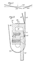
- Figure 1 shows apparatus for feeding and severing a web 2 of transparent film and for feeding successive severed sections 4 of the web into the path of a packet 6.
- the apparatus forms part of a machine for wrapping in transparent film cigarette packets 6 delivered in line from a cigarette packing machine.
- the web 2 is a composite web, having a longitudinally-extending tear strip adhesively secured to it in conventional manner, and is delivered at a controlled speed to a nip between rolls 8 and 10.
- the roll 8 is driven by a motor 12 and carries a relatively narrow U-shaped cutter 14 which severs the web 2 only in the vicinity of the applied tear strip, so as to produce successive severed leading ends of the tear strip (for ease of unwrapping the final wrapped packets).
- the web 2 passes around an idler roll 16, the position of which is movable along a track 18.
- the track 18 supports a longitudinally-extending threaded shaft 20 carrying a captive nut (not shown) movable with the mounting for the roll. Rotation of the shaft 20 by means of a transmission 22 and motor 24 thus causes movement of the axis of roll 16 along the track 18.
- the web 2 passes from the idler roll 16 to the nip between a main drive roll 26 and a cooperating rubber roll 28.
- the drive roll 26 is driven by a motor 30. Beyond the rolls 26, 28 the web 2 passes across the face 31 of an air mover 32 and subsequently passes between a rotary cutter 34 and a cooperating stationary cutter unit 36.
- the rotary cutter 34 is driven by the motor 12 which drives the roll 8 carrying the tear strip cutter 14.
- the cutter unit 36 has stationary inclined blades 36A and 36B separated by a gap (which corresponds to the position of the tear strip on the web 2), which cooperate with a single transverse blade 34A carried by the cutter 34.
- the blades 36A and 36B are adjustable relative to the blade 34A, by means indicated at 38 in Figure 1, so as to ensure the required contact (or spacing) between the respective blades.
- the stationary cutter unit 36 includes an integral air mover 40, downstream of the blades 36A and 36B, for directing the sections 4, now severed from the web 2, to a nip between opposed pairs of laterally spaced pinch rolls 41, 42 around which respectively pass opposed pairs of laterally spaced timing belts 43, 44.
- Each of the pairs of belts 43, 44 passes around respective drive pulleys 46, 48, which are driven by the motor 30.
- a further air mover 50 is arranged between the laterally spaced belts 43, near their downstream ends, and includes a guide surface 52 which extends down to a position just above the path of the packet 6.
- Each packet 6 is intercepted by a wrapper section 4 and the packet and wrapper section are conveyed by upper and lower conveyors 56, 58 into a folding and sealing section of the wrapping machine, in which the wrapper section is folded and sealed around the packet.
- the roll 8 and cutter 34 are driven by the same motor (12). Cutting of the tear strip by the cutter 14 and severing of the web 2 by the blade 34A (cooperating with blades 36A and 36B) are therefore subject to similar control by control of motor 12.
- the speed of motor 12 is variable during a cutting cycle and controlled such that the speeds of the cutter 14 and the blade 34A are the same as that of the web 2 (controlled by motor 30) during actual cutting but variable at other times.
- each wrapper section 4 should have a single tear strip cut positioned in the same place relative to the length of the section.
- the path length of the web 2 between the cutters 14 and 34 is adjustable, by varying the position of the idler roll 16, so as to be equal to an integral number of wrapper section lengths.
- the air mover 32 downstream of driving rolls 26, 28 produces a stream of air closely following the face 31 of the air mover (due to Coanda effect) so as to guide the web 2 towards the cutter 34.
- the air stream draws the web 2 towards the face 31 of air mover 32 so that no opposing guide surface is required.
- the cutter blades 34A, 36A and 36B sever the web 2 by a shearing action.
- initial severing starts at one side of the web and progresses towards the other side.
- this can result in misalignment or skewing of the subsequently-produced wrapper sections due to release of one side of the section before the other side.
- the blade 34A makes approximately simultaneous contact with the outer parts of the blades 36A and 36B so that two simultaneous shearing actions moving inwards relative to the web 2 are performed. Any asymmetric forces acting on the severed wrapper sections 4 are therefore substantially reduced.
- the blades 36A and 36B could be similarly inclined and for the gap (if any) between them to be centrally located relative to the web 2, it is preferred that the blades extend to opposite sides of a gap the position of which is dictated by the location of the tear strip (and it is normal for this to be positioned off-centre).
- the blades 36A and 36B could be of substantially equal length (and inclination) with a short discontinuity in the blades 36B corresponding to the position of the longitudinal tear strip.
- the severed wrapper sections 4 are guided by air mover 40 towards the pinch rolls 41, 42 of timing belts 43, 44.
- the belts 43, 44 move at a higher peripheral speed that the web 2 so that the wrapper sections 4 are spaced apart by the belts.
- the belts 43, 44 may be lightly urged together (e.g. by an arrangement similar to that described below with reference to Figure 4).
- the air mover 50 directs a stream of air along the surface 52 and this assists conveyance of the leading end of each wrapper section 4 across the path of a packet 6.
- the spacing of packets 6 on the conveyor 54 and the timing and speed of this conveyor relative to the timing and speed of motors 12 and 30 causes each wrapper section 4 to be centrally intercepted by the leading side of a packet 6. Note that by use of the air mover 50 and guide 52 it is unnecessary for each wrapper section 4 to be guided across the path of the packet 6 (as with some conventional arrangements where laterally spaced vacuum bands extend across this path).
- the pusher conveyor 54 Since there is no downwardly extending guide for the wrapper sections 4, it is possible for the pusher conveyor 54 to comprise laterally spaced belts with pushers extending between them and for the conveyor 54 to extend beyond the path of the wrapper sections 4 so that each pusher controls the packet up to and through the path of the wrapper sections 4. Clearly, in that case the end pulley of the conveyor 58 could, if necessary, be moved to the left from its position shown in Figure 1.
- the spacing of pushers on the conveyor 54 is 120 millimetres and the length of each wrapper section is adjustable between 121 and 221 millimetres.
- the speed of conveyor 54 is 1.3 metres/second, that of belts 43, 44 is 5.3 metres/second and that of web 2 is 1.8 metres/second.
- Figure 3 shows in more detail the construction of the air mover 50, including a lead-in guide 60, main housing 62, insert 64 and guide 52.
- the housing 62 and insert 64 define an air chamber 66, to which leads an air supply pipe 68.
- the housing 62 and insert 64 have cooperating internal inclined faces, one of which includes laterally spaced recesses 70 defining air outlet passages for directing air across and along the guide 52.
- Figure 3 also shows an end pulley 72 for one of the laterally spaced belts 43.
- FIG 4 shows a modified arrangement for feeding wrapper sections 4 from the cutter 34 to the path of packets 6.
- Laterally spaced timing belts 80, 81 pass around various idler rolls 82 and around drive pulleys 83 (only one of which is shown in Figure 6).
- the belts 80 pass over a fixed UHMW polyethylene guide 84 supported by mounting blocks 85.
- the belts 81 pass over a similar UHMW polyethylene guide 86, which is movably supported by a load-bearing pivot link 87 and spring units 88 which urge the guide 86 towards the guide 84.
- Each spring unit 88 has a threaded bore containing a compression spring 94 and adjustment screw 93.
- the belts 80, 81 are thus pressed together so as to grip the wrapper sections 4 as they are conveyed. Note that the upper idler rolls 82 do not grip the wrapper sections 4 (as do the pinch rolls 40, 41).
- Wrapper section position sensors 89 which detect the leading (or trailing) edge of each wrapper section 4 by optical (or other conventional) means, are located adjacent the guide 84 (which, for this purpose may comprise laterally spaced sections).
- the sensors 89 are capable of detecting incorrect timing of a wrapper section 4 relative to a packet 6, incorrect speed (i.e. if a section is slipping relative to the belts 80, 81), or if the wrapper section is skew.
- at least one of the sensors 89 includes laterally spaced elements.
- An air mover 90 which is similar to the air mover 50 is located adjacent to the lower end of the guide 84.
- a guide surface 91 extends downward from the air mover 90 and, in this case, includes a portion 91A extending beyond the path of the packet 6.
- the air stream generated across the surface 91 by the air mover 90 helps to ensure correct positioning of the leading edge of the wrapper section: the presence of the section 91A is additionally beneficial in this respect.
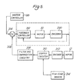
- FIG. 5 is a schematic block diagram of part of the control arrangement for the apparatus of Figure 1.
- a similar control arrangement is usable with the apparatus of Figure 4.
- the web feed motor 30 is connected to a shaft encoder 200 which in turn is linked to a feedback controller 202.
- a first input 204 to the controller 202 derives from a master controller 198 which supplies pulses synchronised with advancement of packets 6 on conveyor 54.
- This basic signal on line 204 is modified by a signal on line 206 which applies a correction dependent on deviation of the position of a wrapper section 4 from an expected position.
- the correction is generated by comparing in a filter circuit 208 the value of a count generated by a counter 210 with an expected value, the value being set by the delay between a horizon pulse received from an encoder 212, which pulse corresponds to the instant when motor 12 causes cutter 34 to sever the web 2, and the instant when a film edge sensor 214, corresponding in function and position to sensor 89 in Figure 4, detects the leading edge of the severed wrapper section 4 between opposed belts 43, 44. Any such deviation results in a correction signal generated by circuit 208 to cause a compensating adjustment of the speed of motor 30.
- the apparatus shown in Figures 6 and 7 is arranged adjacent the path of a packet 6 in apparatus otherwise similar to that of Figure 1 or Figure 4.
- the guide plate 52 (or 91) may extend down from the air mover 50 (or 90) as indicated in Figure 6.
- a vertical guide plate 300 for the wrapper sections 4 extends from a region above the path of the packets 6 to a region below the path.
- the plate 300 has an aperture 302 dimensioned to allow passage of packets 6 through the plate.
- the lower edge of aperture 302 is somewhat lower than the level of the bottom of packets 6 to allow clearance for the end portion of a conveyor (not shown) for the packets.
- the plate 300 carries an air mover 304 which directs a stream of air in a downward direction generally along the plate, so as to assist movement of wrapper sections 4 in the same direction.
- the plate 300 extends below the aperture 302 and is opposed by a further air mover 306 having an air outlet 307, which directs a further stream of air downwards between the plate and another guide plate 308, effectively forming an extension of the air mover 306.
- One side of the air outlet 307 is defined by an edge of a pivotable plate 313.
- the width of the air outlet 307 can be adjusted by pivoting the plate 313 against a resilient seal 314 by means of taper point screws 316, which have a wedging action on the sides of the plate.
- the space between the plates 300 and 308 below the air mover 306 is also enclosed by side plates 310, thereby forming a rectangular section channel 312 for air directed primarily by the air mover 306.
- the air mover 304 may supplement or assist the air flow from the air mover 50 (or 90) in conveying the leading end of each wrapper section 4 across the path of the packets 6.
- the air flow generally follows the plate 300, which therefore effectively acts as a guide for the wrapper sections 4.
- the aperture 302 is narrower than the width of the wrapper sections 4 so that at least at the sides each wrapper section is adjacent a continuous guide surface as it descends past and beyond the path of the packets 6.
- the air mover 306 provides a continuing stream of air principally channelled between the guide plates 300 and 308 in the channel section 312, into which the lower end of each wrapper section 4 descends just before its central portion is intercepted by a packet 6. Subjecting the leading end of the wrapper section 4 to a continuing conveying force helps to maintain the section flat and under control, thereby promoting a good initial wrap of the packet following interception of the section.
Abstract
Description
- This invention relates to article wrapping apparatus, and in particular to such apparatus including means for feeding and severing a web of wrapper material so as to produce wrapper sections for wrapping articles.
- In the tobacco industry it is common to wrap and seal cigarette packets in transparent film wrapper material. Wrapper sections of such material are usually severed from a continuous web. Commonly the web carries a longitudinally extending tear strip provided to facilitate unwrapping of the wrapped packet by the consumer. It is known to sever a part of the strip (and, usually, the underlying wrapper) prior to application of each wrapper section to a packet: the severed leading end thus provides a convenient part of the strip to be grasped and pulled by the consumer. The present invention is particularly, but not exclusively, applicable to wrapping of packets having this form of wrapper section.
- According to a one aspect of the invention article wrapping apparatus includes means for feeding a wrapper web along a path, first severing means at a first position on the path for performing a first severing operation on the web, second severing means at a second position on the path for performing a second severing operation on the web, said second severing operation facilitating division of the leading end of the web into successive separate wrapper sections, means for conveying articles in series, means for conveying successive wrapper sections to a position at which they are intercepted by successive articles delivered by said article conveying means so as to become at least partially wrapped around the leading portions of said articles, and means for varying the path length of the web between said first and second positions so as to control the relative positions on the web of said first and second severing operations. Preferably the apparatus includes means for changing the lengths of successive sections severed from the web. The changing means may include means for varying the freguency of operation of said second severing means and/or the speed of said web feeding means, so as to alter the spacing between cuts in the web.
- In a preferred arrangement the path length is varied so that it remains an integral multiple of the lengths of said wrapper sections. The path length varying means may include means for moving the position of guide means, e.g. an idler roll, around which the web passes between the first and second severing means. In a preferred arrangement movement of the guide means is achieved by drive means, which may be controlled by a microprocessor.
- The apparatus may form part of a wrapping machine for wrapping film material around successive spaced cigarette packets fed in line. The first severing means may comprise a rotary cutter for severing the web, e.g. in the vicinity of a longitudinally extending tear strip adhesively applied to the web upstream of the apparatus. In a particularly preferred arrangement of the apparatus the second severing means also comprises a rotary cutter, which severs the web (and tear strip) into sections. The first cutter is preferably upstream of the second cutter.
- The first and second severing means preferably have common drive means which is preferably separate from drive means for the web feeding means. Preferably the respective drive means comprise separate motors, the speeds of which are electronically controlled. The speeds of said motors may be under overall control of a microprocessor, so that if it is desired to change the lengths of wrapper sections severed from the web, for example, this may be achieved by appropriate software commands to alter the relative speeds of the respective drive means. A preferred way of achieving this is to use software to define rotational positions of the motors at set times. The means for varying the path length may also be under common control of the microprocessor or other software system. This is particularly convenient where the apparatus is required from time to time to produce separate wrapper sections of different lengths, since producing sections of different lengths (e.g. for different sizes of packets) may then be achieved entirely by software commands. Thus, in effect the apparatus may provide a programmable, substantially immediate, size change facility.
- Either of said severing operations, particularly said first severing operation, could comprise a partial severing operation, e.g. production of a line of perforations or other weakening of the web.
- According to another aspect of the invention article wrapping apparatus includes a wrapper web conveying means, means for severing the web into separate sections, and means for conveying said sections towards a position at which they are intercepted by an article around which they will subsequently be wrapped, and air mover means upstream of the severing means for feeding the web towards the severing means. It is known to feed web material to a cutter between opposed guide surfaces utilising air flow produced by a venturi effect between the guide surfaces but we have found that an improvement is achieved (i.e. higher web speeds are possible) if an air mover, in which an air stream follows a guide surface by Coanda effect, acting on one side only of the web path is used. In a preferred arrangement a further air mover is arranged downstream of the severing means for feeding the severed sections towards the article path.
- According to a further aspect of the invention article wrapping apparatus includes wrapper web conveying means, means for severing the web into separate sections, means for conveying articles to be wrapped along a path, means for conveying said wrapper sections towards a position at which they are intercepted by an article on said path and so that they become draped around said article, and an air mover for directing a stream of air along a guide surface extending adjacent said path. Thus the guide surface associated with the air mover may extend right up to the article path, and may extend beyond the article path so that an air stream generated by the air mover may assist conveyance of a wrapper section across the article path prior to interception by an article. The absence of any moving mechanical conveyor (e.g. belt conveyors) extending across the article path allows extension of a conveyor for the articles across the line of conveyance of the wrapper sections, thereby retaining positive control for advancement of the articles beyond the position at which they intercept a wrapper section.
- Preferably an air mover is located beyond the article path in relation to the direction of the feed of the wrapper sections. In this case the leading end of each wrapper section may extend into a channel defined between opposed guide surfaces prior to interception of each section by an article, said air stream extending into said channel. A guide surface may extend from a position located on an upstream side of the article path relative to the direction of travel of the wrapper sections and may have an aperture or window through which articles may pass. The guide surface is preferably continuous at its sides to provide guidance for an air stream and/or the sides of each wrapper section as it passes the aperture or article path.
- Where the article path is generally horizontal with wrapper sections being conveyed downwards across the path for example, air movers could be provided just above and just below the article path, the guide surface being preferably common to both air movers. In a preferred arrangement a guide plate having an aperture for passage of articles cooperates with an opposed air mover beyond the article path. Preferably the guide plate is located upstream of the path of wrapper sections relative to the direction of movement of the articles. The guide plate may have an associated air mover for generating an air stream across and/or along the sides of the aperture.
- According to a still further aspect of the invention article wrapping apparatus includes means for conveying wrapper sections towards an article path at which successive sections are intercepted by an article, including opposed belt conveyors for feeding wrapper sections towards said path and means extending along at least one of said conveyors for urging said conveyors together to clamp wrapper sections during conveyance. Said urging means may comprise a movably supported backing plate for the other conveyor, and air cylinder means for urging the movable plate towards the stationary plate. Clamping of wrapper sections helps to ensure retention of relative timing after severing. Sensors may be provided to detect each wrapper section as it is conveyed by said conveying means and may be connected to control means for compensating for any drift in position of wrapper sections: such compensation would normally be achieved by slight speed adjustments of the conveying means (relative to the article conveying means).
- The different aspects of this invention may be used in any combination, e.g. so that they are embodied in the same apparatus.
- The invention will be further described, by way of example only, with reference to the accompanying diagrammatic drawings, in which:
- Figure 1 is a side view of web feeding and severing apparatus,
- Figure 2 is an enlarged front view of a detail of part of the apparatus of Figure 1,
- Figure 3 is an enlarged sectional view of an air mover usable with the apparatus of Figure 1,
- Figure 4 is a part-sectional side view of part of a modified web feeding and severing apparatus, and
- Figure 5 is a schematic block diagram of a part of a control arrangement for the apparatus of Figure 1,
- Figure 6 is a side view of part of another modified web feed and severing apparatus, and
- Figure 7 is a view in the direction of arrow VII in Figure 6.
- Figure 1 shows apparatus for feeding and severing a web 2 of transparent film and for feeding successive severed sections 4 of the web into the path of a
packet 6. The apparatus forms part of a machine for wrapping in transparentfilm cigarette packets 6 delivered in line from a cigarette packing machine. - The web 2 is a composite web, having a longitudinally-extending tear strip adhesively secured to it in conventional manner, and is delivered at a controlled speed to a nip between rolls 8 and 10. The roll 8 is driven by a
motor 12 and carries a relatively narrow U-shapedcutter 14 which severs the web 2 only in the vicinity of the applied tear strip, so as to produce successive severed leading ends of the tear strip (for ease of unwrapping the final wrapped packets). - From the roll 10 the web 2 passes around an idler roll 16, the position of which is movable along a
track 18. In order to allow variation of the position of the roll 16, thetrack 18 supports a longitudinally-extending threadedshaft 20 carrying a captive nut (not shown) movable with the mounting for the roll. Rotation of theshaft 20 by means of atransmission 22 andmotor 24 thus causes movement of the axis of roll 16 along thetrack 18. - The web 2 passes from the idler roll 16 to the nip between a
main drive roll 26 and a cooperatingrubber roll 28. Thedrive roll 26 is driven by amotor 30. Beyond therolls face 31 of anair mover 32 and subsequently passes between arotary cutter 34 and a cooperatingstationary cutter unit 36. Therotary cutter 34 is driven by themotor 12 which drives the roll 8 carrying thetear strip cutter 14. As best shown in Figure 2, thecutter unit 36 has stationaryinclined blades transverse blade 34A carried by thecutter 34. Theblades blade 34A, by means indicated at 38 in Figure 1, so as to ensure the required contact (or spacing) between the respective blades. - The
stationary cutter unit 36 includes anintegral air mover 40, downstream of theblades timing belts belts motor 30. Afurther air mover 50 is arranged between the laterally spacedbelts 43, near their downstream ends, and includes aguide surface 52 which extends down to a position just above the path of thepacket 6. -
Successive packets 6 are conveyed by apusher conveyor 54 at regular spacing. Eachpacket 6 is intercepted by a wrapper section 4 and the packet and wrapper section are conveyed by upper andlower conveyors - It will be noted that the roll 8 and
cutter 34 are driven by the same motor (12). Cutting of the tear strip by thecutter 14 and severing of the web 2 by theblade 34A (cooperating withblades motor 12. In this respect the speed ofmotor 12 is variable during a cutting cycle and controlled such that the speeds of thecutter 14 and theblade 34A are the same as that of the web 2 (controlled by motor 30) during actual cutting but variable at other times. By controlling the speed ofmotor 12 in this way relative to the speed ofmotor 30 determining speed of the web 2, it is possible to vary the cycle times of thecutter 14 andblade 34A independently of the speed of themotor 30, and thereby vary the lengths of wrapper sections 4 produced by the apparatus. - Normally it is required that each wrapper section 4 should have a single tear strip cut positioned in the same place relative to the length of the section. In order to achieve this for different possible lengths of the section 4 the path length of the web 2 between the
cutters - Since position of idler roll 16 is controllable by
motor 24, and speed ofcutters motor 12, changes in length of wrapper sections 4 can be controlled automatically by appropriate commands tomotors motors 12 and 24 (and 30) to be under control of one or more microprocessors (which may conveniently be incorporated in a master controller 198). - The
air mover 32, downstream of driving rolls 26, 28 produces a stream of air closely following theface 31 of the air mover (due to Coanda effect) so as to guide the web 2 towards thecutter 34. The air stream draws the web 2 towards theface 31 ofair mover 32 so that no opposing guide surface is required. - The
cutter blades blade 34A makes approximately simultaneous contact with the outer parts of theblades blades blades blades 36B corresponding to the position of the longitudinal tear strip. - Downstream of the
cutter 34 the severed wrapper sections 4 are guided byair mover 40 towards the pinch rolls 41, 42 oftiming belts belts belts - The
air mover 50 directs a stream of air along thesurface 52 and this assists conveyance of the leading end of each wrapper section 4 across the path of apacket 6. The spacing ofpackets 6 on theconveyor 54 and the timing and speed of this conveyor relative to the timing and speed ofmotors packet 6. Note that by use of theair mover 50 and guide 52 it is unnecessary for each wrapper section 4 to be guided across the path of the packet 6 (as with some conventional arrangements where laterally spaced vacuum bands extend across this path). Since there is no downwardly extending guide for the wrapper sections 4, it is possible for thepusher conveyor 54 to comprise laterally spaced belts with pushers extending between them and for theconveyor 54 to extend beyond the path of the wrapper sections 4 so that each pusher controls the packet up to and through the path of the wrapper sections 4. Clearly, in that case the end pulley of theconveyor 58 could, if necessary, be moved to the left from its position shown in Figure 1. - In one form of apparatus similar to that shown in Figure 1 the spacing of pushers on the
conveyor 54 is 120 millimetres and the length of each wrapper section is adjustable between 121 and 221 millimetres. At 650 packets per minute the speed ofconveyor 54 is 1.3 metres/second, that ofbelts - Figure 3 shows in more detail the construction of the
air mover 50, including a lead-inguide 60,main housing 62, insert 64 andguide 52. Thehousing 62 and insert 64 define anair chamber 66, to which leads anair supply pipe 68. Thehousing 62 and insert 64 have cooperating internal inclined faces, one of which includes laterally spacedrecesses 70 defining air outlet passages for directing air across and along theguide 52. Figure 3 also shows anend pulley 72 for one of the laterally spacedbelts 43. - Figure 4 shows a modified arrangement for feeding wrapper sections 4 from the
cutter 34 to the path ofpackets 6. Laterally spacedtiming belts belts 80 pass over a fixedUHMW polyethylene guide 84 supported by mountingblocks 85. Thebelts 81 pass over a similarUHMW polyethylene guide 86, which is movably supported by a load-bearing pivot link 87 andspring units 88 which urge theguide 86 towards theguide 84. Eachspring unit 88 has a threaded bore containing acompression spring 94 andadjustment screw 93. Thebelts - Wrapper
section position sensors 89, which detect the leading (or trailing) edge of each wrapper section 4 by optical (or other conventional) means, are located adjacent the guide 84 (which, for this purpose may comprise laterally spaced sections). Thesensors 89 are capable of detecting incorrect timing of a wrapper section 4 relative to apacket 6, incorrect speed (i.e. if a section is slipping relative to thebelts 80, 81), or if the wrapper section is skew. For the last purpose at least one of thesensors 89 includes laterally spaced elements. - An
air mover 90, which is similar to theair mover 50 is located adjacent to the lower end of theguide 84. A guide surface 91 extends downward from theair mover 90 and, in this case, includes aportion 91A extending beyond the path of thepacket 6. The air stream generated across the surface 91 by theair mover 90 helps to ensure correct positioning of the leading edge of the wrapper section: the presence of thesection 91A is additionally beneficial in this respect. - Figure 5 is a schematic block diagram of part of the control arrangement for the apparatus of Figure 1. A similar control arrangement is usable with the apparatus of Figure 4. The
web feed motor 30 is connected to ashaft encoder 200 which in turn is linked to afeedback controller 202. Afirst input 204 to thecontroller 202 derives from amaster controller 198 which supplies pulses synchronised with advancement ofpackets 6 onconveyor 54. This basic signal online 204 is modified by a signal online 206 which applies a correction dependent on deviation of the position of a wrapper section 4 from an expected position. The correction is generated by comparing in afilter circuit 208 the value of a count generated by acounter 210 with an expected value, the value being set by the delay between a horizon pulse received from anencoder 212, which pulse corresponds to the instant whenmotor 12causes cutter 34 to sever the web 2, and the instant when afilm edge sensor 214, corresponding in function and position tosensor 89 in Figure 4, detects the leading edge of the severed wrapper section 4 betweenopposed belts circuit 208 to cause a compensating adjustment of the speed ofmotor 30. - The apparatus shown in Figures 6 and 7 is arranged adjacent the path of a
packet 6 in apparatus otherwise similar to that of Figure 1 or Figure 4. Thus, the guide plate 52 (or 91) may extend down from the air mover 50 (or 90) as indicated in Figure 6. Avertical guide plate 300 for the wrapper sections 4 extends from a region above the path of thepackets 6 to a region below the path. Theplate 300 has anaperture 302 dimensioned to allow passage ofpackets 6 through the plate. The lower edge ofaperture 302 is somewhat lower than the level of the bottom ofpackets 6 to allow clearance for the end portion of a conveyor (not shown) for the packets. At its upper end theplate 300 carries anair mover 304 which directs a stream of air in a downward direction generally along the plate, so as to assist movement of wrapper sections 4 in the same direction. - The
plate 300 extends below theaperture 302 and is opposed by afurther air mover 306 having anair outlet 307, which directs a further stream of air downwards between the plate and anotherguide plate 308, effectively forming an extension of theair mover 306. One side of theair outlet 307 is defined by an edge of apivotable plate 313. The width of theair outlet 307 can be adjusted by pivoting theplate 313 against aresilient seal 314 by means of taper point screws 316, which have a wedging action on the sides of the plate. The space between theplates air mover 306 is also enclosed byside plates 310, thereby forming arectangular section channel 312 for air directed primarily by theair mover 306. - In use, the
air mover 304 may supplement or assist the air flow from the air mover 50 (or 90) in conveying the leading end of each wrapper section 4 across the path of thepackets 6. The air flow generally follows theplate 300, which therefore effectively acts as a guide for the wrapper sections 4. Note that theaperture 302 is narrower than the width of the wrapper sections 4 so that at least at the sides each wrapper section is adjacent a continuous guide surface as it descends past and beyond the path of thepackets 6. Theair mover 306 provides a continuing stream of air principally channelled between theguide plates channel section 312, into which the lower end of each wrapper section 4 descends just before its central portion is intercepted by apacket 6. Subjecting the leading end of the wrapper section 4 to a continuing conveying force helps to maintain the section flat and under control, thereby promoting a good initial wrap of the packet following interception of the section.
Claims (23)
- Article wrapping apparatus including means (26, 28) for feeding a wrapper web (2) along a path, first severing means (14) at a first position on the path for performing a first severing operation on the web, second severing means (34A) at a second position on the path for performing a second severing operation on the web, said second severing operation facilitating division of the leading end of the web into successive separate wrapper sections (4), means (54) for conveying articles (6) in series, means (43, 44; 80, 81) for conveying successive wrapper sections to a position at which they are intercepted by successive articles delivered by said article conveying means so as to become at least partially wrapped around the leading portions of said articles, and means (16-24) for varying the path length of the web between said first and second positions so as to control the relative positions on the web of said first and second severing operations.
- Apparatus as claimed in claim 1, including means (198) for changing the lengths of successive sections (4) severed from the web (2).
- Apparatus as claimed in claim 2, wherein said changing means includes means (12, 198) for altering the frequency of operation of said second severing means (34A).
- Apparatus as claimed in claim 2 or claim 3, wherein said changing means includes means (30, 198) for altering the speed of said web feeding means (26, 28).
- Apparatus as claimed in any of claims 2-4, wherein said varying means (16-24) includes means arranged to maintain said path length and the lengths of said wrapper sections (4) in a predetermined relationship.
- Apparatus as claimed in any preceding claim, including common drive means (12) for said first and second severing means (14; 34A).
- Apparatus as claimed in claim 6, wherein said web feeding means (26, 28) and said wrapper section conveying means (43, 44; 80, 81) each include drive means (30) which is separate from said common drive means (12).
- Apparatus as claimed in any preceding claim, wherein the first severing means (14) is upstream of said second severing means (34A) and arranged to make a cut in a predetermined position in each wrapper section (4).
- Apparatus as claimed in any preceding claim, wherein the path length varying means comprises means (18-24) for relocating guide means (16) for the web (2) on said path between said first and second positions.
- Apparatus as claimed in claim 9, wherein said guide means comprises a rotary guide (16) and said relocating means includes drive means (20-24) for moving the axis of said rotary guide.
- Apparatus as claimed in claim 10, including a track (18) along which said axis is movable, said drive means (20) extending along said track.
- Apparatus as claimed in any preceding claim, including means (89) for generating a signal on detection of a predetermined portion of a wrapper section (4) conveyed by said wrapper section conveying means (80, 81), means (208, 210) for processing said signal including means for generating a timing signal, and means (30, 202) for correcting relative positions of wrapper sections by adjusting the speed of said wrapper section conveying means.
- Apparatus as claimed in any preceding claim, wherein the second severing means includes a rotary cutter member (34A) cooperating with a stationary member (36A, 36B) to sever the web (2) progressively by a shearing action.
- Apparatus as claimed in claim 13, wherein said rotary and stationary members (34A, 36A, 36B) are arranged to produce separate progressive cuts moving across the web (2) in substantially opposite directions substantially simultaneously.
- Apparatus as claimed in any preceding claim, wherein the wrapper web (2) comprises a main web and a longitudinally extending strip attached to the main web, said first severing means (14) being arranged to sever at least part of said strip.
- Article wrapping apparatus including means (26, 28) for feeding a wrapper web (2), first severing means (34A) for severing successive leading end portions of the web into wrapper sections (4) of predetermined length, means (54) for conveying articles (6) to be wrapped along a path, means (43, 44; 80, 81) for conveying successive wrapper sections to a position at which they are respectively intercepted by successive articles conveyed along said path and thereby initiating wrapping of the articles, second severing means (14) upstream of said first severing means for performing a separate severing operation on the web so that at least one such operation is performed on each portion of the web corresponding to a wrapper section, means (16) defining a variable length path for the web between said first and second severing means, first drive means (30) for said wrapper section conveying means, second drive means for said article conveying means, third drive means (12) for said first severing means, fourth drive means (12) for said second severing means, fifth drive means (24) for moving said path length defining means to vary the length of said path, and control means (198) for said first, second, third, fourth and fifth drive means, said control means including means for synchronising said drives for operation at a plurality of different predetermined lengths of wrapper sections and means for controlling said fifth drive means to maintain said variable path length in a predetermined relationship with the length of a wrapper section.
- Apparatus as claimed in claim 16, wherein said third and fourth drive means comprise common drive means (12).
- Apparatus as claimed in claim 16 or claim 17, further including means (208) for generating a timing signal related to passage of a predetermined portion of a wrapper section (4) conveyed by said wrapper section conveying means, and means (198) for generating a timing signal related to passage of a predetermined portion of an article conveyed by said article conveying means, wherein said control means includes means (202) for comparing said timing signals and for making a corrective adjustment to said first drive means (30) relative to said second drive means so that interception of wrapper sections and articles (6) is synchronised.
- Apparatus as claimed in any of claims 16-18, wherein said wrapper web feeding means (26, 28) is connected to said first drive means (12).
- Article wrapping apparatus including a wrapper web conveying means (26, 28), means (34A) for severing the web (2) into separate sections (4), means (41, 42) for conveying said sections towards a position at which they are intercepted by an article around which they will subsequently be wrapped, and air mover means (31) upstream of the severing means for feeding the web towards the severing means.
- Article wrapping apparatus, including wrapper web conveying means (26, 28), means (34A) for severing the web (2) into separate sections (4), means (54) for conveying articles (6) to be wrapped along a path, means (43,44; 80, 81) for conveying said wrapper sections towards a position at which they are intercepted by an article on said path and so that they become draped around said article, and an air mover (50; 90; 304, 306) for directing a stream of air along a guide surface (52; 91; 302, 308) extending adjacent said path.
- Article wrapping apparatus including means for conveying wrapper sections (4) towards an article path at which successive sections are intercepted by an article (6), including opposed belt conveyors (43, 44; 80, 81) for feeding wrapper sections towards said path, and means (86) extending along at least one of said conveyors for urging said conveyors together to clamp wrapper sections during conveyance.
- Apparatus as claimed in any of claims 1-15 and any of claims 16-22.
Applications Claiming Priority (4)
| Application Number | Priority Date | Filing Date | Title |
|---|---|---|---|
| GB9003675 | 1990-02-17 | ||
| GB909003675A GB9003675D0 (en) | 1990-02-17 | 1990-02-17 | Web handling apparatus |
| GB909025906A GB9025906D0 (en) | 1990-11-28 | 1990-11-28 | Web handling apparatus |
| GB9025906 | 1990-11-28 |
Publications (3)
| Publication Number | Publication Date |
|---|---|
| EP0443787A2 true EP0443787A2 (en) | 1991-08-28 |
| EP0443787A3 EP0443787A3 (en) | 1992-01-02 |
| EP0443787B1 EP0443787B1 (en) | 1995-06-07 |
Family
ID=26296684
Family Applications (1)
| Application Number | Title | Priority Date | Filing Date |
|---|---|---|---|
| EP91301244A Expired - Lifetime EP0443787B1 (en) | 1990-02-17 | 1991-02-15 | Article wrapping apparatus |
Country Status (7)
| Country | Link |
|---|---|
| US (1) | US5179815A (en) |
| EP (1) | EP0443787B1 (en) |
| JP (1) | JPH04242509A (en) |
| CN (1) | CN1026572C (en) |
| AU (1) | AU640587B2 (en) |
| BR (1) | BR9100647A (en) |
| DE (1) | DE69110152T2 (en) |
Cited By (5)
| Publication number | Priority date | Publication date | Assignee | Title |
|---|---|---|---|---|
| EP0589289A2 (en) * | 1992-09-21 | 1994-03-30 | Focke & Co. (GmbH & Co.) | Package for cigarettes |
| EP0795472A1 (en) * | 1996-03-15 | 1997-09-17 | G.D Societa' Per Azioni | Product wrapping method |
| EP1016593A1 (en) * | 1998-12-28 | 2000-07-05 | Focke & Co. (GmbH & Co.) | Cigarette package and method and apparatus for its manufacture |
| EP1279598A2 (en) * | 2001-07-24 | 2003-01-29 | Gianluigi Gamberini | Machine for packaging stacks of articles in wrapping sheets |
| EP1584558A1 (en) * | 2004-04-08 | 2005-10-12 | G.D S.p.A. | A unit for feeding and cutting into lengths a strip of wrapping material |
Families Citing this family (13)
| Publication number | Priority date | Publication date | Assignee | Title |
|---|---|---|---|---|
| IT1261903B (en) * | 1993-03-10 | 1996-06-03 | Sasib Spa | FEEDER FOR PACKAGING SHEETS, IN PARTICULAR IN CIGARETTE PACKING MACHINES. |
| IT1286803B1 (en) * | 1996-12-04 | 1998-07-17 | Gd Spa | METHOD AND FEEDER FOR SHEET MATERIAL |
| GB9725768D0 (en) * | 1997-12-04 | 1998-02-04 | Rothmans International Ltd | Packaging of smoking articles |
| DE19920478C2 (en) * | 1999-05-04 | 2001-05-03 | Windmoeller & Hoelscher | Device for producing and preferably also for filling and closing bags made of thermoplastic material |
| ITBO20000733A1 (en) * | 2000-12-20 | 2002-06-20 | Gianluigi Gamberini | PILE PACKAGING MACHINE FOR MULTI ITEMS - PAPER PITCH OR SIMILAR WITHIN THE RELATED ENVELOPES OBTAINED FROM WRAPPING SHEETS |
| US20060167445A1 (en) * | 2002-08-27 | 2006-07-27 | Gal Shafirstein | Selective conductive interstitial thermal therapy device |
| ITFI20020225A1 (en) * | 2002-11-18 | 2004-05-19 | Noxon S R L | STRETCHING AND PRESTIRO GROUP OF STRETCH FILM WITH SYSTEM |
| US6772043B1 (en) * | 2003-02-05 | 2004-08-03 | T.M.C., S.P.A. | Apparatus for automatically controlling the work flow of an automatic wrapping machine, in particular for rolls of paper |
| US7331153B1 (en) | 2006-08-31 | 2008-02-19 | Sealed Air Corporation (Us) | Apparatus and method for creating easy to open packages |
| US20090238501A1 (en) * | 2008-03-24 | 2009-09-24 | Minkler Douglas J | Pallet Hood Tear Tape |
| ITBO20090453A1 (en) * | 2009-07-15 | 2011-01-16 | Gd Spa | METHOD OF FEEDING MATERIALS DUE INTO A PRODUCT PACKAGING MACHINE AND RELATIVE POWER SUPPLY UNIT. |
| DE202010001587U1 (en) * | 2010-01-29 | 2010-04-22 | Msk - Verpackungs-Systeme Gmbh | Device for wrapping a stack of goods with a film |
| IT201900012426A1 (en) | 2019-07-19 | 2021-01-19 | Tmc Spa | DEVICE FOR FEEDING FILMS FOR PRODUCT PACKAGING. |
Citations (4)
| Publication number | Priority date | Publication date | Assignee | Title |
|---|---|---|---|---|
| DE2644173A1 (en) * | 1975-10-01 | 1977-04-14 | Molins Ltd | DEVICE FOR WRAPPING OBJECTS |
| GB2014938A (en) * | 1978-02-24 | 1979-09-05 | Fuji Photo Film Co Ltd | Packaging machine |
| EP0031515A1 (en) * | 1979-12-11 | 1981-07-08 | FOCKE & CO. | Apparatus for producing packaging blanks by separation from a continuously moving web |
| US4719575A (en) * | 1984-09-14 | 1988-01-12 | Web Printing Control Co., Inc. | Method and apparatus for controlling web handling machinery |
Family Cites Families (6)
| Publication number | Priority date | Publication date | Assignee | Title |
|---|---|---|---|---|
| US2107482A (en) * | 1934-07-25 | 1938-02-08 | Molins Machine Co Ltd | Wrapping or packing machine |
| US3383832A (en) * | 1966-03-07 | 1968-05-21 | John B. Grant | Package wrapping machine |
| US3849969A (en) * | 1973-08-22 | 1974-11-26 | Excel Engineering | Food packing machine |
| US4541225A (en) * | 1982-09-15 | 1985-09-17 | Byland Henry L | Stretch film package wrapping method and apparatus |
| US4620409A (en) * | 1985-01-14 | 1986-11-04 | Kliklok Corporation | Packaging film feed with parallelogram belt support |
| DE3800432A1 (en) * | 1988-01-09 | 1989-07-20 | Hauni Werke Koerber & Co Kg | DEVICE FOR ENHANCING PACKS WITH HULL MATERIAL |
-
1991
- 1991-02-15 DE DE69110152T patent/DE69110152T2/en not_active Expired - Fee Related
- 1991-02-15 EP EP91301244A patent/EP0443787B1/en not_active Expired - Lifetime
- 1991-02-15 AU AU71075/91A patent/AU640587B2/en not_active Ceased
- 1991-02-17 CN CN91101720.8A patent/CN1026572C/en not_active Expired - Fee Related
- 1991-02-18 JP JP3108077A patent/JPH04242509A/en active Pending
- 1991-02-18 BR BR919100647A patent/BR9100647A/en not_active IP Right Cessation
- 1991-02-19 US US07/656,677 patent/US5179815A/en not_active Expired - Fee Related
Patent Citations (4)
| Publication number | Priority date | Publication date | Assignee | Title |
|---|---|---|---|---|
| DE2644173A1 (en) * | 1975-10-01 | 1977-04-14 | Molins Ltd | DEVICE FOR WRAPPING OBJECTS |
| GB2014938A (en) * | 1978-02-24 | 1979-09-05 | Fuji Photo Film Co Ltd | Packaging machine |
| EP0031515A1 (en) * | 1979-12-11 | 1981-07-08 | FOCKE & CO. | Apparatus for producing packaging blanks by separation from a continuously moving web |
| US4719575A (en) * | 1984-09-14 | 1988-01-12 | Web Printing Control Co., Inc. | Method and apparatus for controlling web handling machinery |
Cited By (14)
| Publication number | Priority date | Publication date | Assignee | Title |
|---|---|---|---|---|
| EP0589289A3 (en) * | 1992-09-21 | 1994-06-08 | Focke & Co | Package for cigarettes |
| US5465837A (en) * | 1992-09-21 | 1995-11-14 | Focke & Co. (Gmbh & Co.) | Packs for cigarettes |
| CN1042619C (en) * | 1992-09-21 | 1999-03-24 | 福克有限公司 | Packs for cigarettes |
| EP0589289A2 (en) * | 1992-09-21 | 1994-03-30 | Focke & Co. (GmbH & Co.) | Package for cigarettes |
| CN1081571C (en) * | 1996-03-15 | 2002-03-27 | 吉第联合股份公司 | Product wrapping method |
| EP0795472A1 (en) * | 1996-03-15 | 1997-09-17 | G.D Societa' Per Azioni | Product wrapping method |
| US5845464A (en) * | 1996-03-15 | 1998-12-08 | G.D Societa Per Azioni | Product wrapping method |
| EP1016593A1 (en) * | 1998-12-28 | 2000-07-05 | Focke & Co. (GmbH & Co.) | Cigarette package and method and apparatus for its manufacture |
| US6523682B1 (en) | 1998-12-28 | 2003-02-25 | Focke & Co. (Gmbh & Co.) | Cigarette pack and process and apparatus for producing the same |
| EP1279598A2 (en) * | 2001-07-24 | 2003-01-29 | Gianluigi Gamberini | Machine for packaging stacks of articles in wrapping sheets |
| EP1279598A3 (en) * | 2001-07-24 | 2003-04-23 | Gianluigi Gamberini | Machine for packaging stacks of articles in wrapping sheets |
| EP1584558A1 (en) * | 2004-04-08 | 2005-10-12 | G.D S.p.A. | A unit for feeding and cutting into lengths a strip of wrapping material |
| US7437982B2 (en) | 2004-04-08 | 2008-10-21 | G.D S.P.A. | Unit for feeding and cutting into lengths a strip of wrapping material |
| CN100478256C (en) * | 2004-04-08 | 2009-04-15 | 吉地股份公司 | A unit for feeding and cutting into lengths a strip of wrapping material |
Also Published As
| Publication number | Publication date |
|---|---|
| US5179815A (en) | 1993-01-19 |
| AU640587B2 (en) | 1993-08-26 |
| CN1026572C (en) | 1994-11-16 |
| DE69110152D1 (en) | 1995-07-13 |
| DE69110152T2 (en) | 1995-10-19 |
| EP0443787B1 (en) | 1995-06-07 |
| JPH04242509A (en) | 1992-08-31 |
| EP0443787A3 (en) | 1992-01-02 |
| AU7107591A (en) | 1991-08-22 |
| BR9100647A (en) | 1991-10-29 |
| CN1054749A (en) | 1991-09-25 |
Similar Documents
| Publication | Publication Date | Title |
|---|---|---|
| US5179815A (en) | Article wrapping apparatus | |
| US4106265A (en) | Wrapping machine and method with four side rotary tucker | |
| US4385479A (en) | Apparatus for the preparation of packaging blanks by severing from a continuous web | |
| US4524658A (en) | Apparatus for producing packaging blanks | |
| US4151699A (en) | Production of discrete blanks for packets | |
| JPS6186351A (en) | Raw fabric reel changeover method for packaging machine and device thereof | |
| US5845464A (en) | Product wrapping method | |
| US4211599A (en) | Cut-and-weld device for superimposed foils advanced in the form of strips | |
| EP0640526A1 (en) | Method and device for manipulating a stream of products | |
| US3557156A (en) | Sectional drive apparatus for continuously feeding an elastic material | |
| US5461954A (en) | Method and device for feeding portions of wrapping material to a packing line | |
| US20060059863A1 (en) | Bander apparatus and method of using same | |
| JP7314471B2 (en) | Separator | |
| US4209956A (en) | Forming overlapped wrappers | |
| EP0822886B1 (en) | Method and apparatus for cutting superposed webs | |
| JPH10218123A (en) | Apparatus for feeding wrapping material tape for cigarettes or cigarette package | |
| US5327702A (en) | Wrapping articles | |
| EP0830068B1 (en) | An indexer for moving food along a processing line in a precise manner | |
| EP1547927A2 (en) | A device for feeding and cutting film in machines for conditioning products | |
| US20220135264A1 (en) | Feeding unit for feeding a plastic film in packaging machines | |
| GB2290533A (en) | Wrapping articles | |
| EP1799553B1 (en) | Bander apparatus and method of using same | |
| US2561097A (en) | Sheet delivery control for cutoff mechanisms | |
| GB2154923A (en) | Severing sheets from a web | |
| US5359833A (en) | Method of depositing extruded pieces of substances onto individual wrapping sheets and apparatus for carrying out the method |
Legal Events
| Date | Code | Title | Description |
|---|---|---|---|
| PUAI | Public reference made under article 153(3) epc to a published international application that has entered the european phase |
Free format text: ORIGINAL CODE: 0009012 |
|
| AK | Designated contracting states |
Kind code of ref document: A2 Designated state(s): CH DE DK ES FR GB IT LI NL SE |
|
| PUAL | Search report despatched |
Free format text: ORIGINAL CODE: 0009013 |
|
| AK | Designated contracting states |
Kind code of ref document: A3 Designated state(s): CH DE DK ES FR GB IT LI NL SE |
|
| 17P | Request for examination filed |
Effective date: 19920622 |
|
| 17Q | First examination report despatched |
Effective date: 19930817 |
|
| GRAA | (expected) grant |
Free format text: ORIGINAL CODE: 0009210 |
|
| RAP1 | Party data changed (applicant data changed or rights of an application transferred) |
Owner name: MOLINS PLC |
|
| AK | Designated contracting states |
Kind code of ref document: B1 Designated state(s): CH DE DK ES FR GB IT LI NL SE |
|
| PG25 | Lapsed in a contracting state [announced via postgrant information from national office to epo] |
Ref country code: NL Effective date: 19950607 Ref country code: LI Effective date: 19950607 Ref country code: ES Free format text: THE PATENT HAS BEEN ANNULLED BY A DECISION OF A NATIONAL AUTHORITY Effective date: 19950607 Ref country code: DK Effective date: 19950607 Ref country code: CH Effective date: 19950607 |
|
| ITF | It: translation for a ep patent filed |
Owner name: BARZANO' E ZANARDO ROMA S.P.A. |
|
| ET | Fr: translation filed | ||
| REF | Corresponds to: |
Ref document number: 69110152 Country of ref document: DE Date of ref document: 19950713 |
|
| PG25 | Lapsed in a contracting state [announced via postgrant information from national office to epo] |
Ref country code: SE Effective date: 19950907 |
|
| REG | Reference to a national code |
Ref country code: CH Ref legal event code: PL |
|
| NLV1 | Nl: lapsed or annulled due to failure to fulfill the requirements of art. 29p and 29m of the patents act | ||
| PLBE | No opposition filed within time limit |
Free format text: ORIGINAL CODE: 0009261 |
|
| STAA | Information on the status of an ep patent application or granted ep patent |
Free format text: STATUS: NO OPPOSITION FILED WITHIN TIME LIMIT |
|
| 26N | No opposition filed | ||
| PGFP | Annual fee paid to national office [announced via postgrant information from national office to epo] |
Ref country code: FR Payment date: 19970106 Year of fee payment: 7 |
|
| PGFP | Annual fee paid to national office [announced via postgrant information from national office to epo] |
Ref country code: GB Payment date: 19970124 Year of fee payment: 7 |
|
| PGFP | Annual fee paid to national office [announced via postgrant information from national office to epo] |
Ref country code: DE Payment date: 19970214 Year of fee payment: 7 |
|
| PG25 | Lapsed in a contracting state [announced via postgrant information from national office to epo] |
Ref country code: GB Free format text: LAPSE BECAUSE OF NON-PAYMENT OF DUE FEES Effective date: 19980215 |
|
| PG25 | Lapsed in a contracting state [announced via postgrant information from national office to epo] |
Ref country code: FR Free format text: THE PATENT HAS BEEN ANNULLED BY A DECISION OF A NATIONAL AUTHORITY Effective date: 19980228 |
|
| GBPC | Gb: european patent ceased through non-payment of renewal fee |
Effective date: 19980215 |
|
| PG25 | Lapsed in a contracting state [announced via postgrant information from national office to epo] |
Ref country code: DE Free format text: LAPSE BECAUSE OF NON-PAYMENT OF DUE FEES Effective date: 19981103 |
|
| REG | Reference to a national code |
Ref country code: FR Ref legal event code: ST |
|
| PG25 | Lapsed in a contracting state [announced via postgrant information from national office to epo] |
Ref country code: IT Free format text: LAPSE BECAUSE OF NON-PAYMENT OF DUE FEES Effective date: 20050215 |