EP0443443A2 - Remote management system for photographic equipment - Google Patents
Remote management system for photographic equipment Download PDFInfo
- Publication number
- EP0443443A2 EP0443443A2 EP91102102A EP91102102A EP0443443A2 EP 0443443 A2 EP0443443 A2 EP 0443443A2 EP 91102102 A EP91102102 A EP 91102102A EP 91102102 A EP91102102 A EP 91102102A EP 0443443 A2 EP0443443 A2 EP 0443443A2
- Authority
- EP
- European Patent Office
- Prior art keywords
- data
- computer
- sub
- photographic equipment
- management system
- Prior art date
- Legal status (The legal status is an assumption and is not a legal conclusion. Google has not performed a legal analysis and makes no representation as to the accuracy of the status listed.)
- Granted
Links
- 238000004891 communication Methods 0.000 claims abstract description 59
- 238000004519 manufacturing process Methods 0.000 claims abstract description 48
- 230000002159 abnormal effect Effects 0.000 claims abstract description 13
- 238000012546 transfer Methods 0.000 claims description 23
- 239000000243 solution Substances 0.000 description 42
- 238000007726 management method Methods 0.000 description 34
- 238000012545 processing Methods 0.000 description 26
- 238000000034 method Methods 0.000 description 23
- 230000008569 process Effects 0.000 description 14
- 238000010586 diagram Methods 0.000 description 9
- 238000012360 testing method Methods 0.000 description 7
- 244000309464 bull Species 0.000 description 6
- 238000011161 development Methods 0.000 description 6
- 238000012937 correction Methods 0.000 description 4
- 230000002093 peripheral effect Effects 0.000 description 4
- 238000005375 photometry Methods 0.000 description 4
- 238000004061 bleaching Methods 0.000 description 3
- 239000007844 bleaching agent Substances 0.000 description 3
- 238000003745 diagnosis Methods 0.000 description 3
- 238000001035 drying Methods 0.000 description 3
- 239000013589 supplement Substances 0.000 description 3
- 238000012384 transportation and delivery Methods 0.000 description 3
- 230000003139 buffering effect Effects 0.000 description 2
- 238000001739 density measurement Methods 0.000 description 2
- 230000003203 everyday effect Effects 0.000 description 2
- 230000006870 function Effects 0.000 description 2
- 238000010438 heat treatment Methods 0.000 description 2
- 238000012986 modification Methods 0.000 description 2
- 230000004048 modification Effects 0.000 description 2
- 230000003287 optical effect Effects 0.000 description 2
- 238000013439 planning Methods 0.000 description 2
- IOLCXVTUBQKXJR-UHFFFAOYSA-M potassium bromide Chemical compound [K+].[Br-] IOLCXVTUBQKXJR-UHFFFAOYSA-M 0.000 description 2
- 230000000087 stabilizing effect Effects 0.000 description 2
- 230000032258 transport Effects 0.000 description 2
- 238000003326 Quality management system Methods 0.000 description 1
- 238000004458 analytical method Methods 0.000 description 1
- 238000004364 calculation method Methods 0.000 description 1
- 230000008859 change Effects 0.000 description 1
- 238000005520 cutting process Methods 0.000 description 1
- 230000002354 daily effect Effects 0.000 description 1
- 238000003780 insertion Methods 0.000 description 1
- 230000037431 insertion Effects 0.000 description 1
- 239000000463 material Substances 0.000 description 1
- 230000007246 mechanism Effects 0.000 description 1
- 239000000047 product Substances 0.000 description 1
- 230000000717 retained effect Effects 0.000 description 1
- 239000012487 rinsing solution Substances 0.000 description 1
- 230000035945 sensitivity Effects 0.000 description 1
- 238000000926 separation method Methods 0.000 description 1
- 238000002834 transmittance Methods 0.000 description 1
Images


Classifications
-
- G—PHYSICS
- G03—PHOTOGRAPHY; CINEMATOGRAPHY; ANALOGOUS TECHNIQUES USING WAVES OTHER THAN OPTICAL WAVES; ELECTROGRAPHY; HOLOGRAPHY
- G03D—APPARATUS FOR PROCESSING EXPOSED PHOTOGRAPHIC MATERIALS; ACCESSORIES THEREFOR
- G03D13/00—Processing apparatus or accessories therefor, not covered by groups G11B3/00 - G11B11/00
- G03D13/007—Processing control, e.g. test strip, timing devices
-
- G—PHYSICS
- G03—PHOTOGRAPHY; CINEMATOGRAPHY; ANALOGOUS TECHNIQUES USING WAVES OTHER THAN OPTICAL WAVES; ELECTROGRAPHY; HOLOGRAPHY
- G03B—APPARATUS OR ARRANGEMENTS FOR TAKING PHOTOGRAPHS OR FOR PROJECTING OR VIEWING THEM; APPARATUS OR ARRANGEMENTS EMPLOYING ANALOGOUS TECHNIQUES USING WAVES OTHER THAN OPTICAL WAVES; ACCESSORIES THEREFOR
- G03B27/00—Photographic printing apparatus
- G03B27/32—Projection printing apparatus, e.g. enlarger, copying camera
Definitions
- the present invention relates to a system for remotely controlling the operation condition of a photographic equipment and the production and quality at a lab shop, and more particularly to a remote management system suitable for centralized management of a plurality of minilab shops.
- a compact and economical photographic equipment such as a printer processor and a film processor
- a minilab equipment has been recently used widely.
- Such a minilab equipment is often installed, for example, within a super market at a minilab department (minilab shop) to provide photoprinting services as a sideline.
- minilab shop minilab department
- Even an operator having less photofinishing knowledge can make a properly finished photographic print (photoprint) using a minilab equipment having automated functions.
- a minilab equipment is usually operated by an operator with photofinishing knowledge insufficient for proper check and adjustment. Therefore, photofinishing may sometimes be carried out under improper conditions of the equipment. Such a case may also occur even at a large lab having a number of experts, if a plurality of causes are complicated.
- an operation condition management system or and quality management system is provided independently to both a minilab shop and a large lab to analyze a trouble or adjustment failure of a photographic equipment.
- This management system is constituted by a personal computer and an analysis program, and is used at the start of daily work, at the time of a poorly finished print, or as a routine work.
- a control strip supplied from a film maker is first developed in a printer processor. Then, the developed control strip is measured with a densitometer to obtain density data. The density data is inputted into a personal computer through its keyboard so that the operation condition of a processor in the printer processor can be diagnosed from the finished quality of the control strip. If the operation condition is abnormal, the causes of trouble or adjustment failure are analyzed and displayed on the screen of the personal computer. The operator checks the displayed causes and adjusts the processor to have a proper condition. It is therefore possible to make a photoprint having a good quality by using the printer processor which recovered a normal operation condition.
- the operation condition is different with photographic equipments in an actual photoprinting system.
- Such operation data (setting data and measured data) specific to each photographic equipment has not been supplied to the above-described management system, so that check and adjustment suitable for each photographic equipment have been impossible.
- the conventional management system is intended to be used for analyzing trouble and adjustment failure for the case of a standard production state. Accordingly, although the conventional management system can analyze trouble and adjustment failure caused by temporary changes, it cannot correctly analyze trouble and adjustment failure caused by a difference of production amount and contents.
- a photographic equipment is operated under automatic control in accordance with various preset data such that measured data becomes equal to the preset data.
- Various data preset for the photographic equipment can be used for quality management, production management, consumable goods management, operation condition management, operation condition history record, analysis of trouble and adjustment failure, and the like.
- the data format is different between a photographic equipment and a personal computer while data communication cannot be made during the operation of a photographic equipment.
- the conventional management system uses a photographic equipment and a personal computer in off-line. It becomes therefore necessary for an operator to input data into a personal computer through its keyboard and adjust the photographic equipment in accordance with the analyzed causes.
- the foregoing and other objects of this invention are achieved by connecting a photographic equipment and a densitometer to a computer, e.g., a personal computer, measuring a check sample made by the photographic equipment with the densitometer, entering on-line the measured density data into the computer, and diagnosing the operation condition of the photographic equipment or the quality of a photoprint by analyzing the measured density data. If the operation condition of the photographic equipment is abnormal, data in concern is picked up from the photographic equipment to determine a countermeasure which is then transmitted back to the photographic equipment to adjust the operation condition.
- the photographic equipment may be a film processor, a printer processor, a photofinishing reception unit and the like as minilab equipments.
- a large lab it may be a film processor, a printer, a paper processor, a negative film analyzer, a notch puncher, and the like.
- various data of a photographic equipment is transferred on-line to a computer so that, by referring to the data, an optimum countermeasure for an abnormal operation condition can be determined using a management program stored in the computer.
- An optimum countermeasure specific to each photographic equipment can be automatically determined so that even an operator with insufficient photofinishing knowledge can provide precise operation management.
- each lab shop is installed with a sub-computer such as a personal computer which is connected to a photographic equipment and a densitometer. Production data from the photographic equipment and density data from the densitometer are entered into the sub-computer.
- This sub-computer is connected via a communication line to a main computer at the headquarters.
- the main computer at the headquarters fetches data from the sub-computer, and analyzes the measured density data by using a management program stored in the main computer while taking production data into consideration, to thereby diagnose the operation condition of the photographic equipment and the quality of a photoprint.
- photographic equipments at lab shops of a chain are collectively managed by the main computer at the headquarters, thereby providing a finite quality of each lab shop.
- a sub-computer fetches production data of a photographic equipment for production management and for determination of a state of consumable goods.
- the sub-computer orders consumable goods on-line to the main computer at the headquarters via a communication line.
- the headquarters can collectively manage production states of lab shops. Since each lab shop automatically orders consumable goods to the headquarters, a timely order is possible by taking delivery time into consideration.
- each photographic equipment and peripheral equipment are connected via a port controller to a computer such as a personal computer.
- This port controller is constructed of a switch unit, a first communication control unit, a buffer memory, a subject communication discriminator unit, a data format converter unit, and a second communication control unit.
- the switch unit selects a photographic equipment for data communication therewith from a plurality of photographic equipments.
- the first communication control unit checks an idle time of a CPU built in the selected photographic equipment and performs data transfer during the idle time at the data transfer speed of the CPU.
- the buffer memory stores data picked up irregularly from the photographic equipment.
- the subject communication discriminator unit discriminates if the data in the buffer memory to be transferred to the computer is the data of the photographic equipment requested by the computer.
- the data format converter unit converts the data read from the buffer memory into the data format of the computer.
- the second communication control unit transfers data in units of block to the computer at the data transfer speed of the computer. According to this embodiment, a photographic equipment and a computer having different data formats can be interconnected on-line. Furthermore, data of the photographic equipment can be entered into the computer without hindering the operation of the photographic equipment.
- a plurality of photographic equipments and peripheral equipments are connected to a bus line 10.
- the printer processors 11a and 11e and film processors 11b and 11f store various preset data, and are operated in accordance with these data.
- the preset data and measured data regularly or irregularly measured are supplied via a port controller 12 to a computer, e.g., a personal computer 13.
- Data is transferred little by little to the port controller 12 during an idle time of CPUs built in the printer processors and film processors so as not to intercept the operation thereof.
- the port controller 12 discriminates the data while referring to the ID data assigned to each photographic equipment. If the data is proper, its format is converted and transferred to the personal computer 13.
- the densitometer 11c measures the density of a check sample made by the printer processors 11a, 11e and film processors 11b and 11f at the time when the operation conditions thereof are checked. The measured density data is supplied via the port controller 12 to the personal computer 13. It is necessary to know which photographic equipment made the check sample, so that the measured density data together with the ID data of the photographic equipment is sent to the personal computer 13.
- the personal computer 13 is constructed of, as well known, a personal computer main unit 14, a monitor 15, and a keyboard 16. According to a management program, the personal computer 13 manages the operation condition of each photographic equipment such that each photographic equipment is adjusted by updating the preset data so as to provide optimum photofinishing, and that if adjustment is impossible, an alarm is generated.
- the number of minilab equipments installed in an ordinary minilab shop is four or less in many cases. Therefore, it is advantageous from the viewpoint of cost and operation efficiency that the maximum number of equipments connectable to the port controller 12 be limited to four.
- a corresponding plurality of port controllers each having the limited connection number of four are used to manage the equipments with one personal computer, as shown in Fig.9 or 10.
- one master port controller 12a and a slave port controller 12b connected to the master port controller 12a are used to manage seven photographic equipments and peripheral equipments in total.
- four slave port controllers 12b to 12e and one master port controller 12a are used to manage sixteen photographic equipments and the like in total.
- a printer processor 11a is constructed of a printer 23 for printing exposure, and a processor 24 for development.
- Color paper 26 wound in a roll is contained within a magazine 25 mounted on the printer 23. This color paper 26 is pulled out from the magazine 25 one frame after another and conveyed to an exposure station provided with a paper mask 27.
- a frame of a negative film 28 is printed within the frame of the color paper 26 at the exposure stage. This negative film is held by a film carrier 29 and illuminated by a printing light radiated from a lamp 30.
- a cyan filter 31, magenta filter 32 and yellow filter 33 whose insertion amounts to the optical path are controlled in accordance with printing exposure amount.
- the printing light passed through the color correction filters 31 to 33 is sufficiently mixed at a mixing box 34, and thereafter applied to the negative film 28.
- Reference numeral 35 is a shutter which maintains open for a predetermined time during printing exposure.
- a test print is carried out using a control negative film (Bull's eye negative film) 36.
- a control negative film Bull's eye negative film
- This control negative film 36 is set on the film carrier 29 to make a test photoprint.
- the exposure condition setting data is corrected such that the density of the test photoprint becomes equal to that of a reference photoprint.
- a photometry sensor 37 obliquely above the film carrier 29 to measure the three color densities and lamp light amount for the negative film 28.
- the exposed color paper 26 is sent to the processor 24 via a looper 40.
- a developing tank 41 There are provided within the processor 24 a developing tank 41, a fixing tank 42, rinsing tanks 43a to 43c, a dryer unit 44, a cutter unit 45, and a sorter unit 46.
- the exposed color paper 26 passes through respective tanks at a predetermined speed to undergo the developing, fixing and rinsing processes. After these photofinishing processes, there are performed a drying process, frame cutting process, and sorting process for each order.
- a control paper strip 49 supplied from a film maker is used.
- This control paper strip 49 is formed with unexposed area, under exposed area, and over exposed area on a color paper, and is light-tightly housed within a cassette 48.
- the cassette 48 is loaded within the processor 24 and the control paper strip 49 therein is guided into the processing tanks and is developed.
- the developed control paper strip 49 is measured with the densitometer 11c so that the operation condition of the processor 24 can be diagnosed based upon the density of the finished control paper strip 49. If a densitometer is built in the printer processor 11a, a check sample can be automatically measured with this built-in densitometer.
- a densitometer 45a is mounted for example at the cutter unit 45 to measure the reflection density of a check sample after the drying process.
- thermosensor 51a to 51e for detecting the temperature of each processing solution, heaters for heating each processing solution up to a predetermined temperature, and other devices.
- the developing tank 41 is supplemented with a fresh developing solution contained within a reserve tank 53 by a pump 54 in accordance with the paper processing amount.
- Reserve tanks 55 and 57 contain fresh fixing solution and rinsing solution, respectively, which are supplement by means of pumps 56 and 58 to the fixing tank 42 and rinsing tanks 43a to 43c, respectively, in accordance with the paper processing amount.
- the rinsing tanks 43a to 43c are cascade-connected in succession.
- Reference numeral 59 represents a control circuit board.
- Fig.3 shows the circuit arrangement of the printer processor.
- CPU 63 controls the circuit elements in accordance with a control program stored in ROM 64.
- CPU 63 causes a pulse motor 66 to rotate by supplying drive pulses to a driver 65, so that a paper transportation system 67 constructed of a number of rollers shown in Fig.2 is driven. Since the rotation amount of the pulse motor 66 corresponds to the paper processing amount, drive pulses after setting a paper are counted by a counter 68. The contents of the counter 68 are fetched by CPU 63 which then obtains the processing amount for each type of paper.
- Written in RAM 69 are production data such as the processing amount for each paper type, the number of prints for each print size, the number of prints for each film type, and the like.
- a photometry sensor 37 measures the light passed through the negative film 28 or control negative film 36 by means of three color separation photometry.
- An output signal of the photometry sensor 37 is converted into a digital signal by an A/D converter 70 and sent to CPU 63 for calculation of three color exposure amounts or for checking the lamp light amount.
- a motor group 71 is constructed of three pulse motors for driving the color correction filters 31 to 33, the rotation of the motor group 71 being controlled by CPU 63 via a drive unit 72.
- the shutter 35 opens or closes the printing optical path by means of a driving mechanism 73.
- Reference numeral 74 represents a driver for the lamp 30.
- a temperature sensor group 51 is constructed of the five temperature sensors 51a to 51e shown in Fig.2, and measures the solution temperature within respective processing tanks. The five measured solution temperatures are converted into digital signals by an A/D converter 79 and supplied to CPU 63 which then writes them in RAM 69 as the measured solution temperature data. If the measured solution temperature of the developing solution for example is lower than the solution temperature setting data, the heater mounted on the developing tank 41 among the heater group 81 is powered via a drive unit 80 to heat the developing solution up to a preset temperature.
- a pump group 82 is constructed of the pumps 54, 56 and 58 shown in Fig.2, and driven by a drive unit 83 in accordance with the total paper processing amount.
- a supply amount measuring sensor group 84 is constructed of three sensors mounted on the pumps 54, 56, and 58, and measures the supply amount of each processing solution in accordance with the drive amount of the pumps. The obtained supply amount is converted into a digital signal by an A/D converter 85 and written in RAM 69.
- An alarm 86 is driven by CPU 63 via a driver 87 to generate a sound, light or the like to warn an operator, when an abnormal state occurs during the operation of the printer processor 11a, or any adjustment failure occurs due to inability of automatic adjustment by the personal computer 13.
- RAM 69 Written in RAM 69 as operation data are setting data and various measured data obtained at predetermined time intervals or obtained when the personal computer 13 requests it, respectively for operating the printer processor in a normal condition.
- This operation data and the above-described production data are fetched by the personal computer 13 via the port controller 12, and are used for determining a countermeasure against adjustment failure, production management, and the like.
- an LSI card or the like may be used instead of RAM 69.
- a data request command and the like from the port controller 12 are temporarily stored in a buffer memory 88 until an idle time of CPU 63 occurs.
- Reference numeral 89 represents a keyboard from which various operation commands and data are supplied to CPU 63.
- a film cassette 90 requested to be printed is set at a pull-out stage. After almost all the exposed negative film 91 within the film cassette 90 is pulled out, a cutter 92 is activated to cut the trailing portion of the negative film 91.
- the exposed negative film 91 passes at a predetermined speed through a color developing tank 93, a bleaching tank 94, a bleach/fixing tank 95, rinsing tanks 96a and 96b, and a stabilizing tank 97 to sequentially undergo the color developing process, bleaching process, bleach/fixing process, rinsing process, and fixing process. After these photofinishing processes, the negative film 91 is sent through a dryer unit 98 to a film stocker 99.
- a control film strip supplied from a film maker is used.
- This control film strip is formed with a non-exposed area, under exposed area, and over exposed area on a negative film, and contained in a film cassette.
- the control film strip is developed in a similar manner as for ordinary negative film development.
- the developed control film strip is measured with the densitometer to diagnose the operation condition of the film processor 11b based upon the density of the finished strip.
- thermosensor 103a to 103f for detecting the temperature of each processing solution, heaters for heating each processing solution up to a predetermined temperature, solution surface detectors, and other devices.
- a fresh color developing solution contained within a reserve tank 104 becomes supplement to the color developing tank 93 by a pump 105 in accordance with the paper processing amount.
- Reserve tanks 106 to 109 also contain fresh solutions, respectively, which become supplement through pumps 110 to 113 to the bleaching tank 94, bleach/fixing tank 95, rinsing tanks 96a and 96b, and stabilizing tank 97, respectively, in accordance with the film processing amount.
- the rinsing tanks 96a and 96b are cascade-connected in succession.
- Reference numeral 114 represents a control circuit board.
- Fig.5 shows the circuit arrangement of the film processor.
- CPU 120 controls the circuit elements in accordance with a control program stored in ROM 121.
- CPU 120 causes a pulse motor 123 to rotate by supplying drive pulses to a driver 122, so that a paper transportation system 124 constructed of a number of rollers shown in Fig.4 is driven to transport the negative film 91 at a predetermined speed. Since the rotation amount of the pulse motor 122 corresponds to the film processing amount, drive pulses after setting a film are counted by a counter 125. The contents of the counter 125 are fetched by CPU 120 which then obtains the measured processing amount data (the number of processed films for each film type) and writes it in RAM 126.
- a temperature sensor group 103 is constructed of the six temperature sensors 103a to 103f, and measures the solution temperatures within respective processing tanks. The six measured solution temperatures are converted into digital signals by an A/D converter 128 and supplied to CPU 120 which then writes them in RAM 126 as the measured solution temperature data.
- a pump group 131 is constructed of the pumps 105, 110 to 113, and driven by a drive unit 132 in accordance with the film processing amount.
- a supply amount measuring sensor group 133 is constructed of five sensors mounted on the pumps, and measures the supply amount of each processing solution in accordance with the drive amount of the pumps. The measured supply amount is converted into a digital signal by an A/D converter 134 and written in RAM 126.
- An alarm 135 is driven by CPU 120 via a driver 136 to generate a sound, light or the like to warn an operator, when an abnormal state occurs during the operation of the film processor 11b, or any adjustment failure occurs due to inability of automatic adjustment by use of the personal computer 13.
- RAM 126 Written in RAM 126 are setting data and various measured data for operating the film processor 11b in a normal condition. These data are fetched by the personal computer 13 via the port controller 12.
- Reference numeral 137 represents a keyboard from which various operation commands and data are supplied to CPU 120.
- Reference numeral 138 represents a buffer memory.
- Fig.6 shows the structure of the densitometer.
- Two lamps 141 and 142 are connected to a driver 140, the lamp 141 being turned on to measure the transmittance density, and the lamp 142 being turned on to measure the reflection density.
- the transmitted light or reflected light from a test sample 143 (control strip, test photoprint, reference photoprint) is measured by a photosensor 144.
- a signal measured by the photosensor 144 is converted into a digital signal by an A/D converter 145 which is then fetched by CPU 146.
- This CPU 146 calculates the density in accordance with a program stored in ROM 147, and the calculated density is written in RAM 148 as the measured data.
- the measured density is also supplied via a driver 149 to a display 150 to display it thereon.
- Reference numeral 151 represents an input key for inputting an ID data or the like of the photographic equipment by which a test sample was made.
- Reference numeral 152 represents a buffer memory connected to the port controller 12.
- Fig.7 shows a photofinishing reception unit which is constructed of a label issue unit 155 for issuing a photofinishing bag and a label with a reception number to be attached to a film cassette, an order sheet issue unit 156 for issuing a photofinishing order sheet, a receipt issue unit 157, a RAM 158 for storing reception data, a ROM 159, a keyboard 160, a buffer memory 161, and a CPU 162.
- the reception data includes a development charge for each film type, a print charge for each print size, the number of ordered films, the number of returned films, and the like.
- the charge also includes a charge for each customer and a total charge for all customers.
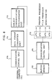
- Fig.8 shows the structure of the port controller.
- a switch unit 170 is selectively turned on by a communication control unit 171 to transfer data or commands via the selected switch to the photographic equipment or densitometer.
- the communication control unit 171 regulates the communication speed so as to be compatible with the data transfer speed of the photographic equipment or densitometer, or performs time sharing control when operation data or production data is fetched from each photographic equipment at predetermined time intervals.
- the port controller 12 transfers data or commands by checking an idle time of CPU so as not to hinder the operation of each photographic equipment. While the photographic equipment operates, data is transferred irregularly, and data transfer to the personal computer 13 is carried out in an ordinary manner. For this reason, there is provided a buffer memory 172 for storing one block of data.
- a subject communication discriminator unit 173 stores in advance the correspondence between the connection terminals of the switch unit 170 and the ID data of photographic equipments connected to the terminals.
- the stored ID data is compared with the ID data which was fetched from the photographic equipment together with the operation data, so that the operation data can be discriminated whether it was fetched from the subject photographic equipment which the personal computer has designated. If both the ID data are not coincident, data transfer to the personal computer 13 is not carried out.
- a data format converter unit 174 converts various formats outputted from the photographic equipment or densitometer into a predetermined format such as ASCII codes readable by the personal computer 13. On the contrary, commands or data sent from the personal computer 13 are converted into a format readable by each photographic equipment.
- a communication control unit 175 responds to a command from the personal computer 13 and transfers the data stored in the buffer memory 172 in units of block and at a predetermined communication speed. It also receives data from the personal computer 13.
- Fig.11 there will be described data communication between the port controller and each photographic equipment.
- Data from a particular photographic equipment or densitometer is fetched into the personal computer 13 via the port controller 12 upon operating the keyboard 16 of the personal computer 13, or data under management by each photographic equipment is automatically fetched at predetermined time intervals in a time sharing manner.
- the operation condition, production, and the like are managed.
- the communication control unit 175 of the port controller 12 analyzes the received read command to identify the subject photographic equipment. For example, assuming that the printer processor 11a has been designated, the data format converter unit 174 converts the read command into the data format suitable for the printer processor 11a.
- the communication control unit 171 turns on the switch of the switch unit 170 connected to the printer processor 11a so that the read command is written in the buffer memory 88 of the printer processor 11a via the turned-on switch at the data communication speed of the printer processor 11a.
- the hatched portion represents a communication disabled time during which CPU 63 performs printing processes.
- CPU 63 When CPU 63 is released from the printing process upon the lapse of a buffering time T1, it fetches the read command written in the buffer memory 88. After fetching the read command, CPU 63 writes an echo-back code into the buffer memory 88 as representative of the completion of fetching the read command.
- the communication control unit 171 reads the echo-back code from the buffer memory 88 at a speed corresponding to the data transfer speed of the printer processor 11a. This echo-back code is converted into an ASCII code and transferred to the personal computer 13.
- the personal computer 13 then sends the start address of RAM 69 to the port controller 12. This start address is written in the buffer memory 88 of the printer processor 11a in a procedure similar to the above-described read command. If CPU 63 is idle, the echo-back code is sent via the buffer memory 88 to the port controller 12. Next, CPU 63 reads data, e.g., of one byte, from RAM 69 at the area designated by the start address, and sends it via the buffer memory 88 to the port controller 12. In a similar manner as above, by using the idle time of CPU 63, one byte data is sequentially read from RAM 69 at the areas following the area designated by the start address, sent to the port controller 12, and written in the buffer memory 172. Reference characters T2 and T3 indicate buffering times.
- the subject communication discriminator unit 173 checks if the collected data is correct with reference to its ID data. This operation is carried out by checking if the ID data which was fetched together with the one block data from the printer processor 11a is coincident with the ID data designated by the personal computer 13. If the one block data is correct, it is read from the buffer memory 172, converted into ASCII codes by the data format converter unit 174, and sequentially transferred to the personal computer 13 via the communication control unit 175. In accordance with the data fetched from the printer processor 11a, the personal computer 13 diagnoses the operation condition, manages the production and consumable goods, and performs other necessary tasks.
- the personal computer 13 can also send data to the printer processor 11a in order to modify the setting data written in the printer processor 11a.
- This data modification can be carried out in a procedure similar to the above-described data fetching, so the description thereof is omitted.
- Data communication with the film processor 11b, densitometer 11c, photofinishing reception unit 11d, and the like is also carried out in a procedure similar to that of the printer processor 11a.
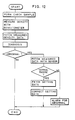
- the operation condition management for a photographic equipment will be described with reference to Fig.12.
- the cover (not shown) of the printer processor is opened to set the cassette 48.
- the leader of the control paper strip 49 is pulled out from the cassette 48 and set to the feed roller pair. Thereafter the cover is closed.
- the control paper strip 49 passes through the developing tank 41, fixing tank 42, and rinsing tanks 43a to 43c sequentially in this order to undergo the developing process. At last it is dried and ejected out into the sorter 46 as a check sample.
- This check sample is measured with the densitometer 11c.
- the ID data of the printer processor which made the check sample is written in RAM 148 by means of the input key 151.
- the check sample is set to the densitometer 11c to measure three color densities.
- the obtained densities are written in RAM 148 as the measured data.
- the measured density data is supplied via the port controller 12 to the personal computer 13. Specifically, when the data is sent to the port controller 12, the communication control unit 171 turns on the switch connected to the densitometer 11c and sets the data transfer speed of CPU 146 of the densitometer 11c.
- the measured data of one block together with the ID data written in RAM 148 is sent to the port controller 12 and stored in the buffer memory 172.
- the subject communication discriminator unit 173 compares the stored ID data with the ID data fetched together with the measured data. If the measured data is correct, it is sent to the data format converter unit 174 to convert it into ASCII codes.
- the communication control unit 175 transfers the data to the personal computer 13 at a speed as high as the data transfer speed of the personal computer 13. In the case of a printer processor with a densitometer built therein, a check sample is automatically measured with the built-in densitometer 45a after the drying process, and the measured density data is written in RAM 69. The measured density data is read and supplied to the personal computer 13 via the port controller 12.
- the personal computer 13 analyzes the measured density data and diagnoses the operation condition, in accordance with a management program. For this diagnosis, source data combining for example nine densities is used as [LD (R, G, B)' C (R, G, B)' Dmin (R, G, B) ].
- R represents red
- G represents green
- B represents blue.
- LD represents a low density (density at a low illuminance area) and corresponds to the sensitivity value of a color paper.
- C represents a contrast which is a difference between a high density (density at a high illuminance area) and a low density.
- Dmin represents a density at an unexposed area and corresponds to a fog value.
- the operation condition is diagnosed as normal. If they are out of the range, the causes of abnormal conditions of the processor 24 are analyzed.
- the personal computer 13 has abnormal source data and knowledge data composed of the causes and countermeasures of abnormal conditions. Therefore, through a pattern matching process, the data the most analogous to the source data of a check sample is derived, and the causes and countermeasures corresponding to the derived data are obtained.
- An example of a method of analyzing causes is detailed in the specification of USSN 450,981 filed on December 15, 1989.
- the printer processor which made the check sample is designated in accordance with the ID data to supply measured data associated with the causes to the personal computer 13.
- Measured data associated with the causes generally include, in addition to the temperature of a processing solution, pH of a developing solution, a concentration of potassium bromide, a height of solution surface, and the like. No sensor might be provided for measuring some of these data. If such a data is necessary despite the lack of the corresponding sensor, the personal computer 13 generates an alarm data and sends it to the printer processor 11a to actuate the alarm 86.
- a solution temperature sensor is provided in this embodiment. Therefore, the following description is directed to the case where the temperature of the developing solution for example is a cause of trouble in development so that a countermeasure is carried out to change the temperature of the developing solution by a predetermined amount.
- the port controller 12 accesses the printer processor 11a to be checked in accordance with an instruction from the personal computer 13, and fetches the measured solution temperature data and ID data stored in RAM 69 and stores them in the buffer memory 172 of the port controller 12. After checking the ID data and confirming that the temperature data is correct, the data format is converted and thereafter, the measured solution temperature data of the developing solution is transferred to the personal computer 13.
- the personal computer 13 diagnoses that the temperature sensor or heater is in trouble, and sends an alarm data to the printer processor 11a. If the measured solution temperature data is within the normal range, the solution temperature setting data stored in RAM 69 is fetched via the port controller 12. The solution temperature setting data is then raised or lowered by a designated amount and written in RAM 69 of the printer processor 11a. The printer processor 11a powers the heater to set the solution temperature to the corrected solution temperature in accordance with the corrected solution temperature setting data.
- the measured supply amount data and setting data of the developing solution are fetched by the personal computer 13 in accordance with the above-described procedure, and the corrected data is written in RAM 69.
- the operation condition of the film processor 11b is checked in a similar manner described above, so the description thereof is omitted.
- the control negative film (Bull's eye) 36 is used and its base portion where a Bull's eye is not formed is set to the film carrier 29.
- Light passed through the base portion is measured with the photosensor 37, converted into a digital signal, and written in RAM 69.
- the measured lamp light amount data is fetched by the personal computer 13 via the port controller 12 in the manner as described above.
- the personal computer 13 judges if the measured lamp light amount is within the normal range. If it is not within the normal range, an alarm data is transferred to the printer 23. If within the normal range, a lamp voltage data is fetched from RAM 69. The lamp voltage is corrected in accordance with a deviation of light amount, and the corrected lamp voltage data is written in RAM 69. The corrected lamp voltage is applied to the lamp 30 to adjust the lamp light amount to a predetermined value.
- the exposure condition is set or corrected after checking the lamp light amount, three Bull's eyes (normal, over, and under) of the control negative film 36 are printed on a color paper 26 which is then developed by the processor unit 24 to obtain check samples including a normal-exposure photoprint, over-exposure photoprint, and under-exposure photoprint.
- the ID data of the printer processor 11b is entered, three photoprints each are set to the densitometer 11c to measure the three color densities of each photoprint.
- the measured density data is fetched by the personal computer 13 via the port controller 12.
- the three reference photoprints each are set to the densitometer 11c to measure three color densities.
- the measured density data is transferred to the personal computer 13 via the port controller 12. It is sufficient if this density measurement is carried out once, except a particular case. Accordingly, if the density measurement of the reference photoprints has finished already, it can be omitted.
- the personal computer 13 compares the density of the normal-exposure reference photoprint with that of the newly printed normal-exposure photoprint to obtain a density difference therebetween. In accordance with this density difference and a balance value fetched from RAM 62 in advance, a corrected balance value is calculated. The corrected balance value is transferred to the printer processor 11a and written in RAM 69. Similarly, the over-exposure reference photoprint is compared with the over-exposure photoprint, and the corrected over-exposure slope value is calculated from the present over-exposure slope value. The corrected under-exposure slope value is obtained in a similar manner. These corrected slope values are written in RAM 69. In the above manner, the personal computer 13 corrects the exposure condition setting data (balance value, slope value). It is apparent that the exposure condition can be set and corrected by operating the keyboard 87 of the printer processor as conventional.
- the personal computer 13 has a function to automatically fetch the operation data of each photographic equipment at predetermined time intervals so as to monitor if the heaters or pumps for example are operating normally or so as to store the operation data in a floppy disk or the like as the operation history data.
- the production management for each photographic equipment becomes possible by collecting the film developing amount data and printing amount data at predetermined time intervals, e.g., every day.
- the sale management for print charges can be conducted by fetching the data from the photofinishing reception unit 11d and supplying it into the personal computer 13.
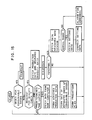
- Fig.13 shows an embodiment wherein the headquarters collectively manage the transactions of a plurality of minilab shops. Minilab shops are often constructed as a chain so that it is convenient if the headquarters and minilab shops are interconnected by a computer network.
- a personal computer 13 of a minilab shop 180 is used as a sub-computer which is connected to a modem 181.
- a minilab shop 182 has the same system.
- the headquarters 190 are provided with a main computer 191, a modem 192, and a printer 193.
- the modem 192 is connected to the modems 181 and 186 of the minilab shops 180 and 182 via communication lines 187 and 188, respectively.
- a high level personal computer is used as the main computer 191 in which a management program is stored.
- a low level inexpensive personal computer is used as the sub-computers 13 and 185.
- the headquarters 190 can manage the business transactions of the plurality of minilab shops 180 and 181. It is therefore convenient if the distance between the headquarters 180 and minilab shops 180 and 182 is too long to allow easy spatial transfer. Since the operation condition of the photographic equipments of each minilab shop can be kept the same, the same quality can be retained between at each minilab shops of a chain.
- the sub-computer sequentially fetches the production data written in RAM of each photographic equipment at predetermined time intervals in a time sharing manner. For example, from a printer processor, the sub-computer fetches a paper processing amount for each paper type, and the number of prints (the number of prints for each print size, the number of prints for each film type). From a film processor, the sub-computer fetches the number of processed films for each film type. The sub-computer processes the production data of each photographic equipment to obtain the primary production management data such as the production amount per period.
- the sub-computer calculates the consumed amount of consumable goods such as paper, processing solution, print ink ribbon, and the like.
- the sub-computer automatically orders the consumable goods to the main computer 191 at the headquarters 190 via the communication line.
- the rated amount is determined for each of the consumable goods while taking into consideration the delivery time and consumed amount at each photographic equipment.
- the order amount is determined in a similar manner.
- the photofinishing reception unit 11d stores as its reception data the development charge, print charge, number of ordered films, number of returned films. This reception data is also fetched by the sub-computer at predetermined time intervals.
- a check sample is made to measure the density thereof with a densitometer.
- the measured density data is fetched by the sub-computer via the port controller. After fetching the measured density data, the sub-computer requests the main computer 191 to check the quality.
- the main computer 191 of the headquarters 190 prints out an order sheet from a printer 193.
- consumable goods are delivered at right time from the headquarters 190.
- the main computer 191 fetches from each sub-computer the production data and reception data at predetermined time intervals, e.g., every day.
- the main computer 191 generates the achieved production data, estimated consumable goods order data, production planning data, and the like, respectively for each minilab shop and for all minilab shops.
- the main computer 191 In accordance with the fetched reception data, the main computer 191 generates the balance sheet for each minilab shop and for all minilab shops. Upon reception of a quality check from the sub-computer, the main computer 191 fetches at high speed the measured data and production data managed by the sub-computer via the communication line. While taking into consideration the production data, the measured density data is analyzed to diagnose the photofinishing quality. If the diagnosed results are abnormal, the setting data is corrected or an alarm is generated from the buzzer, as described with Fig.12. At the printer unit of the printer processor, similar diagnosis and countermeasure are provided.
- the main computer 191 is connected on-line to the main frame computer of a film maker or a wholesale dealer of photographic materials, it becomes possible to obtain the latest exposure condition setting data or the like from the film maker or wholesale dealer. If the production data such as a printing amount is sent to the film maker or the like via the communication line, the stock amount of consumable goods at the headquarters can be requested to be managed by the film maker, thereby minimizing the stock cost. On the other hand, the film maker can obtain various information from users so that such information can help the production planning and commodity development.
Abstract
Description
- The present invention relates to a system for remotely controlling the operation condition of a photographic equipment and the production and quality at a lab shop, and more particularly to a remote management system suitable for centralized management of a plurality of minilab shops.
- A compact and economical photographic equipment (such as a printer processor and a film processor) called a minilab equipment has been recently used widely. Such a minilab equipment is often installed, for example, within a super market at a minilab department (minilab shop) to provide photoprinting services as a sideline. Even an operator having less photofinishing knowledge can make a properly finished photographic print (photoprint) using a minilab equipment having automated functions.
- It is necessary to check and adjust a photographic equipment in order to attain a proper quality of a photoprint. A minilab equipment is usually operated by an operator with photofinishing knowledge insufficient for proper check and adjustment. Therefore, photofinishing may sometimes be carried out under improper conditions of the equipment. Such a case may also occur even at a large lab having a number of experts, if a plurality of causes are complicated. In order to ensure a proper quality of a photoprint, an operation condition management system or and quality management system is provided independently to both a minilab shop and a large lab to analyze a trouble or adjustment failure of a photographic equipment. This management system is constituted by a personal computer and an analysis program, and is used at the start of daily work, at the time of a poorly finished print, or as a routine work. In using this management system, a control strip supplied from a film maker is first developed in a printer processor. Then, the developed control strip is measured with a densitometer to obtain density data. The density data is inputted into a personal computer through its keyboard so that the operation condition of a processor in the printer processor can be diagnosed from the finished quality of the control strip. If the operation condition is abnormal, the causes of trouble or adjustment failure are analyzed and displayed on the screen of the personal computer. The operator checks the displayed causes and adjusts the processor to have a proper condition. It is therefore possible to make a photoprint having a good quality by using the printer processor which recovered a normal operation condition.
- The operation condition is different with photographic equipments in an actual photoprinting system. Such operation data (setting data and measured data) specific to each photographic equipment has not been supplied to the above-described management system, so that check and adjustment suitable for each photographic equipment have been impossible. Furthermore, the conventional management system is intended to be used for analyzing trouble and adjustment failure for the case of a standard production state. Accordingly, although the conventional management system can analyze trouble and adjustment failure caused by temporary changes, it cannot correctly analyze trouble and adjustment failure caused by a difference of production amount and contents.
- A photographic equipment is operated under automatic control in accordance with various preset data such that measured data becomes equal to the preset data. Various data preset for the photographic equipment can be used for quality management, production management, consumable goods management, operation condition management, operation condition history record, analysis of trouble and adjustment failure, and the like. Generally, the data format is different between a photographic equipment and a personal computer while data communication cannot be made during the operation of a photographic equipment. For these and other reasons, the conventional management system uses a photographic equipment and a personal computer in off-line. It becomes therefore necessary for an operator to input data into a personal computer through its keyboard and adjust the photographic equipment in accordance with the analyzed causes.
- For the production management of each photographic equipment, there has been adopted a method of making a note of the number of finished products, e.g., the number of film strips for a film processor or the number of photoprints for a printer processor, and thereafter summing the numbers on the note. This method does not provide correct production management, due to forgetting to write the number on a note or missing a note. Furthermore, an operator of a minilab shop of a chain orders consumable goods such as color paper and processing solution to the headquarters when necessary. It has been difficult to order at right time in consideration of delivery time and the like. Furthermore, the headquarters cannot collectively manage the production at a plurality of lab shops.
- It is therefore an object of this invention to provide a remote management system capable of precisely analyzing the operation conditions of photographic equipments or the quality of photoprints by taking the state of each photographic equipment into consideration.
- It is another object of this invention to provide a remote management system capable of precisely analyzing the operation conditions and qualities of photographic equipments by taking production data into consideration.
- It is a further object of this invention to provide a remote management system capable of automatically and remotely adjusting a photographic equipment when the adjustment is necessary after diagnosis.
- It is a still further object of this invention to provide a remote management system capable of providing precise production management and a timely order of consumable goods to headquarters.
- It is another object of this invention to provide a remote management system capable of collectively managing production of each lab shop at headquarters.
- It is a further object of this invention to provide a remote management system capable of entering data under management of a photographic equipment into a personal computer without hindering the operation of the photographic equipment.
- The foregoing and other objects of this invention are achieved by connecting a photographic equipment and a densitometer to a computer, e.g., a personal computer, measuring a check sample made by the photographic equipment with the densitometer, entering on-line the measured density data into the computer, and diagnosing the operation condition of the photographic equipment or the quality of a photoprint by analyzing the measured density data. If the operation condition of the photographic equipment is abnormal, data in concern is picked up from the photographic equipment to determine a countermeasure which is then transmitted back to the photographic equipment to adjust the operation condition. The photographic equipment may be a film processor, a printer processor, a photofinishing reception unit and the like as minilab equipments. At a large lab it may be a film processor, a printer, a paper processor, a negative film analyzer, a notch puncher, and the like. According to the present invention, various data of a photographic equipment is transferred on-line to a computer so that, by referring to the data, an optimum countermeasure for an abnormal operation condition can be determined using a management program stored in the computer. An optimum countermeasure specific to each photographic equipment can be automatically determined so that even an operator with insufficient photofinishing knowledge can provide precise operation management.
- According to a preferred embodiment of this invention, each lab shop is installed with a sub-computer such as a personal computer which is connected to a photographic equipment and a densitometer. Production data from the photographic equipment and density data from the densitometer are entered into the sub-computer. This sub-computer is connected via a communication line to a main computer at the headquarters. The main computer at the headquarters fetches data from the sub-computer, and analyzes the measured density data by using a management program stored in the main computer while taking production data into consideration, to thereby diagnose the operation condition of the photographic equipment and the quality of a photoprint. According to this embodiment, photographic equipments at lab shops of a chain are collectively managed by the main computer at the headquarters, thereby providing a finite quality of each lab shop.
- According to another preferred embodiment of this invention, a sub-computer fetches production data of a photographic equipment for production management and for determination of a state of consumable goods. When consumable goods are consumed by a predetermined amount, the sub-computer orders consumable goods on-line to the main computer at the headquarters via a communication line. According to this embodiment, the headquarters can collectively manage production states of lab shops. Since each lab shop automatically orders consumable goods to the headquarters, a timely order is possible by taking delivery time into consideration.
- According to a further embodiment of this invention, each photographic equipment and peripheral equipment are connected via a port controller to a computer such as a personal computer. This port controller is constructed of a switch unit, a first communication control unit, a buffer memory, a subject communication discriminator unit, a data format converter unit, and a second communication control unit. The switch unit selects a photographic equipment for data communication therewith from a plurality of photographic equipments. The first communication control unit checks an idle time of a CPU built in the selected photographic equipment and performs data transfer during the idle time at the data transfer speed of the CPU. The buffer memory stores data picked up irregularly from the photographic equipment. The subject communication discriminator unit discriminates if the data in the buffer memory to be transferred to the computer is the data of the photographic equipment requested by the computer. The data format converter unit converts the data read from the buffer memory into the data format of the computer. The second communication control unit transfers data in units of block to the computer at the data transfer speed of the computer. According to this embodiment, a photographic equipment and a computer having different data formats can be interconnected on-line. Furthermore, data of the photographic equipment can be entered into the computer without hindering the operation of the photographic equipment.
- The above objects and advantages of this invention will become apparent to the person skilled in the art from the following detailed description of the invention when read in conjunction with the accompanying drawings, in which:
- Fig.1 is a schematic illustration of a remote management system of this invention;
- Fig.2 is a schematic diagram showing the printer processor shown in Fig.1;
- Fig.3 is a block diagram showing the electric circuit arrangement of the printer processor shown in Fig.2;
- Fig.4 is a schematic diagram showing the film processor shown in Fig.1;
- Fig.5 is a block diagram showing the electric circuit arrangement of the film processor shown in Fig.4;
- Fig.6 is a schematic diagram of the densitometer shown in Fig.1;
- Fig.7 is a schematic diagram showing the photofinishing reception equipment shown in Fig.1;
- Fig.8 is a block diagram showing the port controller shown in Fig.1;
- Fig.9 is a block diagram of an embodiment wherein seven photographic equipments are connectable using two port controllers;
- Fig.10 is a block diagram showing another embodiment wherein sixteen photographic equipments are connectable using five port controllers;
- Fig.11 illustrates a communication state between a port controller and a photographic equipment;
- Fig.12 is a flow chart showing an example of the operation management procedure for a photographic equipment;
- Fig.13 illustrates an embodiment wherein the headquarters and a plurality of minilab shops are connected via communication lines;
- Fig.14 is a flow chart showing the tasks in a sub-computer; and
- Fig.15 is a flow chart showing the tasks in a main computer.
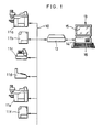
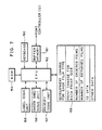
- Referring to Fig.1 showing the outline of the present invention, a plurality of photographic equipments and peripheral equipments are connected to a
bus line 10. In this embodiment, connected to thebus line 10 are twoprinter processors film processors densitometer 11c, and aphotofinishing reception equipment 11d. Theprinter processors film processors port controller 12 to a computer, e.g., apersonal computer 13. Data is transferred little by little to theport controller 12 during an idle time of CPUs built in the printer processors and film processors so as not to intercept the operation thereof. When data of one block is collected, theport controller 12 discriminates the data while referring to the ID data assigned to each photographic equipment. If the data is proper, its format is converted and transferred to thepersonal computer 13. Thedensitometer 11c measures the density of a check sample made by theprinter processors film processors port controller 12 to thepersonal computer 13. It is necessary to know which photographic equipment made the check sample, so that the measured density data together with the ID data of the photographic equipment is sent to thepersonal computer 13. - There are required at least one printer processor and one film processor for photoprinting, and one densitometer for operation condition checking. Therefore, the two processors and one densitometer preferably constitute one set. Each set is connected to the
port controller 12. Thepersonal computer 13 is constructed of, as well known, a personal computer main unit 14, amonitor 15, and akeyboard 16. According to a management program, thepersonal computer 13 manages the operation condition of each photographic equipment such that each photographic equipment is adjusted by updating the preset data so as to provide optimum photofinishing, and that if adjustment is impossible, an alarm is generated. - The number of minilab equipments installed in an ordinary minilab shop is four or less in many cases. Therefore, it is advantageous from the viewpoint of cost and operation efficiency that the maximum number of equipments connectable to the
port controller 12 be limited to four. For a relatively large minilab shop or the like having five or more photographic equipments and peripheral equipments, a corresponding plurality of port controllers each having the limited connection number of four are used to manage the equipments with one personal computer, as shown in Fig.9 or 10. In Fig.9, onemaster port controller 12a and aslave port controller 12b connected to themaster port controller 12a are used to manage seven photographic equipments and peripheral equipments in total. In Fig.10, fourslave port controllers 12b to 12e and onemaster port controller 12a are used to manage sixteen photographic equipments and the like in total. - As shown in Fig.2, a
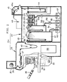
printer processor 11a is constructed of aprinter 23 for printing exposure, and aprocessor 24 for development.Color paper 26 wound in a roll is contained within amagazine 25 mounted on theprinter 23. Thiscolor paper 26 is pulled out from themagazine 25 one frame after another and conveyed to an exposure station provided with apaper mask 27. A frame of anegative film 28 is printed within the frame of thecolor paper 26 at the exposure stage. This negative film is held by afilm carrier 29 and illuminated by a printing light radiated from alamp 30. In order to adjust the proportion and intensity of three color components of the printing light, there are disposed acyan filter 31,magenta filter 32 andyellow filter 33 whose insertion amounts to the optical path are controlled in accordance with printing exposure amount. The printing light passed through the color correction filters 31 to 33 is sufficiently mixed at amixing box 34, and thereafter applied to thenegative film 28.Reference numeral 35 is a shutter which maintains open for a predetermined time during printing exposure. - In setting an exposure condition, a test print is carried out using a control negative film (Bull's eye negative film) 36. As well known, there are formed on a control negative film at least three Bull's eyes of normal, over, and under exposure. This control
negative film 36 is set on thefilm carrier 29 to make a test photoprint. The exposure condition setting data is corrected such that the density of the test photoprint becomes equal to that of a reference photoprint. There is another method of correcting the exposure condition setting data by means of round exposure of the controlnegative film 36. According this method, round exposure is conducted at density correction or color corrections by predetermined steps to make e.g. nine test photoprints, and the number of the most properly finished one is selected and key-inputted to thereby correct the exposure condition setting data. There is disposed aphotometry sensor 37 obliquely above thefilm carrier 29 to measure the three color densities and lamp light amount for thenegative film 28. - The exposed
color paper 26 is sent to theprocessor 24 via alooper 40. There are provided within the processor 24 a developingtank 41, a fixingtank 42, rinsingtanks 43a to 43c, adryer unit 44, acutter unit 45, and asorter unit 46. The exposedcolor paper 26 passes through respective tanks at a predetermined speed to undergo the developing, fixing and rinsing processes. After these photofinishing processes, there are performed a drying process, frame cutting process, and sorting process for each order. - In order to manage the operation condition of the
processor 24, acontrol paper strip 49 supplied from a film maker is used. Thiscontrol paper strip 49 is formed with unexposed area, under exposed area, and over exposed area on a color paper, and is light-tightly housed within acassette 48. Thecassette 48 is loaded within theprocessor 24 and thecontrol paper strip 49 therein is guided into the processing tanks and is developed. The developedcontrol paper strip 49 is measured with thedensitometer 11c so that the operation condition of theprocessor 24 can be diagnosed based upon the density of the finishedcontrol paper strip 49. If a densitometer is built in theprinter processor 11a, a check sample can be automatically measured with this built-in densitometer. In this case, adensitometer 45a is mounted for example at thecutter unit 45 to measure the reflection density of a check sample after the drying process. - Within the above-described tanks, there are mounted, as well known in the art,
temperature sensors 51a to 51e for detecting the temperature of each processing solution, heaters for heating each processing solution up to a predetermined temperature, and other devices. The developingtank 41 is supplemented with a fresh developing solution contained within areserve tank 53 by apump 54 in accordance with the paper processing amount.Reserve tanks pumps tank 42 and rinsingtanks 43a to 43c, respectively, in accordance with the paper processing amount. The rinsingtanks 43a to 43c are cascade-connected in succession.Reference numeral 59 represents a control circuit board. - Fig.3 shows the circuit arrangement of the printer processor.
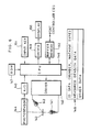
CPU 63 controls the circuit elements in accordance with a control program stored inROM 64.CPU 63 causes apulse motor 66 to rotate by supplying drive pulses to adriver 65, so that apaper transportation system 67 constructed of a number of rollers shown in Fig.2 is driven. Since the rotation amount of thepulse motor 66 corresponds to the paper processing amount, drive pulses after setting a paper are counted by acounter 68. The contents of thecounter 68 are fetched byCPU 63 which then obtains the processing amount for each type of paper. Written inRAM 69 are production data such as the processing amount for each paper type, the number of prints for each print size, the number of prints for each film type, and the like. - A
photometry sensor 37 measures the light passed through thenegative film 28 or controlnegative film 36 by means of three color separation photometry. An output signal of thephotometry sensor 37 is converted into a digital signal by an A/D converter 70 and sent toCPU 63 for calculation of three color exposure amounts or for checking the lamp light amount. Amotor group 71 is constructed of three pulse motors for driving the color correction filters 31 to 33, the rotation of themotor group 71 being controlled byCPU 63 via adrive unit 72. Theshutter 35 opens or closes the printing optical path by means of adriving mechanism 73.Reference numeral 74 represents a driver for thelamp 30. - In the
paper transportation system 76 mounted within theprocessor 24, amotor 78 connected to adriver 77 transports the exposedcolor paper 26 at a predetermined speed. Atemperature sensor group 51 is constructed of the fivetemperature sensors 51a to 51e shown in Fig.2, and measures the solution temperature within respective processing tanks. The five measured solution temperatures are converted into digital signals by an A/D converter 79 and supplied toCPU 63 which then writes them inRAM 69 as the measured solution temperature data. If the measured solution temperature of the developing solution for example is lower than the solution temperature setting data, the heater mounted on the developingtank 41 among theheater group 81 is powered via adrive unit 80 to heat the developing solution up to a preset temperature. Apump group 82 is constructed of thepumps sensor group 84 is constructed of three sensors mounted on thepumps RAM 69. Analarm 86 is driven byCPU 63 via adriver 87 to generate a sound, light or the like to warn an operator, when an abnormal state occurs during the operation of theprinter processor 11a, or any adjustment failure occurs due to inability of automatic adjustment by thepersonal computer 13. - Written in
RAM 69 as operation data are setting data and various measured data obtained at predetermined time intervals or obtained when thepersonal computer 13 requests it, respectively for operating the printer processor in a normal condition. This operation data and the above-described production data are fetched by thepersonal computer 13 via theport controller 12, and are used for determining a countermeasure against adjustment failure, production management, and the like. Instead ofRAM 69, an LSI card or the like may be used. In order to preferentially carry out the operation by the photographic equipment, a data request command and the like from theport controller 12 are temporarily stored in abuffer memory 88 until an idle time ofCPU 63 occurs.Reference numeral 89 represents a keyboard from which various operation commands and data are supplied toCPU 63. - Referring to Fig.4 showing the
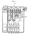
film processor 11b, afilm cassette 90 requested to be printed is set at a pull-out stage. After almost all the exposednegative film 91 within thefilm cassette 90 is pulled out, acutter 92 is activated to cut the trailing portion of thenegative film 91. The exposednegative film 91 passes at a predetermined speed through acolor developing tank 93, a bleaching tank 94, a bleach/fixing tank 95, rinsingtanks tank 97 to sequentially undergo the color developing process, bleaching process, bleach/fixing process, rinsing process, and fixing process. After these photofinishing processes, thenegative film 91 is sent through adryer unit 98 to afilm stocker 99. - In order to manage the operation condition of the
film processor 11b, a control film strip supplied from a film maker is used. This control film strip is formed with a non-exposed area, under exposed area, and over exposed area on a negative film, and contained in a film cassette. The control film strip is developed in a similar manner as for ordinary negative film development. The developed control film strip is measured with the densitometer to diagnose the operation condition of thefilm processor 11b based upon the density of the finished strip. - Within the above-described processing tanks, there are
mounted temperature sensors 103a to 103f for detecting the temperature of each processing solution, heaters for heating each processing solution up to a predetermined temperature, solution surface detectors, and other devices. A fresh color developing solution contained within areserve tank 104 becomes supplement to thecolor developing tank 93 by apump 105 in accordance with the paper processing amount.Reserve tanks 106 to 109 also contain fresh solutions, respectively, which become supplement throughpumps 110 to 113 to the bleaching tank 94, bleach/fixingtank 95, rinsingtanks tank 97, respectively, in accordance with the film processing amount. The rinsingtanks Reference numeral 114 represents a control circuit board. - Fig.5 shows the circuit arrangement of the film processor.
CPU 120 controls the circuit elements in accordance with a control program stored inROM 121.CPU 120 causes apulse motor 123 to rotate by supplying drive pulses to adriver 122, so that apaper transportation system 124 constructed of a number of rollers shown in Fig.4 is driven to transport thenegative film 91 at a predetermined speed. Since the rotation amount of thepulse motor 122 corresponds to the film processing amount, drive pulses after setting a film are counted by acounter 125. The contents of thecounter 125 are fetched byCPU 120 which then obtains the measured processing amount data (the number of processed films for each film type) and writes it inRAM 126. - A
temperature sensor group 103 is constructed of the sixtemperature sensors 103a to 103f, and measures the solution temperatures within respective processing tanks. The six measured solution temperatures are converted into digital signals by an A/D converter 128 and supplied toCPU 120 which then writes them inRAM 126 as the measured solution temperature data. - A
pump group 131 is constructed of thepumps drive unit 132 in accordance with the film processing amount. A supply amount measuringsensor group 133 is constructed of five sensors mounted on the pumps, and measures the supply amount of each processing solution in accordance with the drive amount of the pumps. The measured supply amount is converted into a digital signal by an A/D converter 134 and written inRAM 126. - An
alarm 135 is driven byCPU 120 via adriver 136 to generate a sound, light or the like to warn an operator, when an abnormal state occurs during the operation of thefilm processor 11b, or any adjustment failure occurs due to inability of automatic adjustment by use of thepersonal computer 13. - Written in
RAM 126 are setting data and various measured data for operating thefilm processor 11b in a normal condition. These data are fetched by thepersonal computer 13 via theport controller 12.Reference numeral 137 represents a keyboard from which various operation commands and data are supplied toCPU 120.Reference numeral 138 represents a buffer memory. - Fig.6 shows the structure of the densitometer. Two
lamps driver 140, thelamp 141 being turned on to measure the transmittance density, and thelamp 142 being turned on to measure the reflection density. The transmitted light or reflected light from a test sample 143 (control strip, test photoprint, reference photoprint) is measured by aphotosensor 144. A signal measured by thephotosensor 144 is converted into a digital signal by an A/D converter 145 which is then fetched byCPU 146. ThisCPU 146 calculates the density in accordance with a program stored inROM 147, and the calculated density is written inRAM 148 as the measured data. The measured density is also supplied via adriver 149 to adisplay 150 to display it thereon.Reference numeral 151 represents an input key for inputting an ID data or the like of the photographic equipment by which a test sample was made.Reference numeral 152 represents a buffer memory connected to theport controller 12. - Fig.7 shows a photofinishing reception unit which is constructed of a
label issue unit 155 for issuing a photofinishing bag and a label with a reception number to be attached to a film cassette, an ordersheet issue unit 156 for issuing a photofinishing order sheet, areceipt issue unit 157, aRAM 158 for storing reception data, aROM 159, akeyboard 160, abuffer memory 161, and aCPU 162. The reception data includes a development charge for each film type, a print charge for each print size, the number of ordered films, the number of returned films, and the like. The charge also includes a charge for each customer and a total charge for all customers. - Fig.8 shows the structure of the port controller. A
switch unit 170 is selectively turned on by acommunication control unit 171 to transfer data or commands via the selected switch to the photographic equipment or densitometer. Thecommunication control unit 171 regulates the communication speed so as to be compatible with the data transfer speed of the photographic equipment or densitometer, or performs time sharing control when operation data or production data is fetched from each photographic equipment at predetermined time intervals. - The
port controller 12 transfers data or commands by checking an idle time of CPU so as not to hinder the operation of each photographic equipment. While the photographic equipment operates, data is transferred irregularly, and data transfer to thepersonal computer 13 is carried out in an ordinary manner. For this reason, there is provided abuffer memory 172 for storing one block of data. - A subject
communication discriminator unit 173 stores in advance the correspondence between the connection terminals of theswitch unit 170 and the ID data of photographic equipments connected to the terminals. The stored ID data is compared with the ID data which was fetched from the photographic equipment together with the operation data, so that the operation data can be discriminated whether it was fetched from the subject photographic equipment which the personal computer has designated. If both the ID data are not coincident, data transfer to thepersonal computer 13 is not carried out. A data format converter unit 174 converts various formats outputted from the photographic equipment or densitometer into a predetermined format such as ASCII codes readable by thepersonal computer 13. On the contrary, commands or data sent from thepersonal computer 13 are converted into a format readable by each photographic equipment. Acommunication control unit 175 responds to a command from thepersonal computer 13 and transfers the data stored in thebuffer memory 172 in units of block and at a predetermined communication speed. It also receives data from thepersonal computer 13. - Referring now to Fig.11, there will be described data communication between the port controller and each photographic equipment. Data from a particular photographic equipment or densitometer is fetched into the
personal computer 13 via theport controller 12 upon operating thekeyboard 16 of thepersonal computer 13, or data under management by each photographic equipment is automatically fetched at predetermined time intervals in a time sharing manner. By using these data, the operation condition, production, and the like are managed. - For fetching data from a photographic equipment under operation, it is checked if a CPU of the photographic equipment is idle or not. Namely, if the
personal computer 13 requires data, it sends a read command (including an ID data of the subject photographic equipment) to theport controller 12. Thecommunication control unit 175 of theport controller 12 analyzes the received read command to identify the subject photographic equipment. For example, assuming that theprinter processor 11a has been designated, the data format converter unit 174 converts the read command into the data format suitable for theprinter processor 11a. Thecommunication control unit 171 turns on the switch of theswitch unit 170 connected to theprinter processor 11a so that the read command is written in thebuffer memory 88 of theprinter processor 11a via the turned-on switch at the data communication speed of theprinter processor 11a. - The hatched portion represents a communication disabled time during which
CPU 63 performs printing processes. WhenCPU 63 is released from the printing process upon the lapse of a buffering time T1, it fetches the read command written in thebuffer memory 88. After fetching the read command,CPU 63 writes an echo-back code into thebuffer memory 88 as representative of the completion of fetching the read command. Thecommunication control unit 171 reads the echo-back code from thebuffer memory 88 at a speed corresponding to the data transfer speed of theprinter processor 11a. This echo-back code is converted into an ASCII code and transferred to thepersonal computer 13. - The
personal computer 13 then sends the start address ofRAM 69 to theport controller 12. This start address is written in thebuffer memory 88 of theprinter processor 11a in a procedure similar to the above-described read command. IfCPU 63 is idle, the echo-back code is sent via thebuffer memory 88 to theport controller 12. Next,CPU 63 reads data, e.g., of one byte, fromRAM 69 at the area designated by the start address, and sends it via thebuffer memory 88 to theport controller 12. In a similar manner as above, by using the idle time ofCPU 63, one byte data is sequentially read fromRAM 69 at the areas following the area designated by the start address, sent to theport controller 12, and written in thebuffer memory 172. Reference characters T2 and T3 indicate buffering times. - When one block data is collected in the
buffer memory 172, the subjectcommunication discriminator unit 173 checks if the collected data is correct with reference to its ID data. This operation is carried out by checking if the ID data which was fetched together with the one block data from theprinter processor 11a is coincident with the ID data designated by thepersonal computer 13. If the one block data is correct, it is read from thebuffer memory 172, converted into ASCII codes by the data format converter unit 174, and sequentially transferred to thepersonal computer 13 via thecommunication control unit 175. In accordance with the data fetched from theprinter processor 11a, thepersonal computer 13 diagnoses the operation condition, manages the production and consumable goods, and performs other necessary tasks. - The
personal computer 13 can also send data to theprinter processor 11a in order to modify the setting data written in theprinter processor 11a. This data modification can be carried out in a procedure similar to the above-described data fetching, so the description thereof is omitted. Data communication with thefilm processor 11b,densitometer 11c,photofinishing reception unit 11d, and the like is also carried out in a procedure similar to that of theprinter processor 11a. - The operation condition management for a photographic equipment will be described with reference to Fig.12. For checking the operation condition of the
processor 24 of theprinter processor 11a, the cover (not shown) of the printer processor is opened to set thecassette 48. The leader of thecontrol paper strip 49 is pulled out from thecassette 48 and set to the feed roller pair. Thereafter the cover is closed. When theprocessor 24 operates, thecontrol paper strip 49 passes through the developingtank 41, fixingtank 42, and rinsingtanks 43a to 43c sequentially in this order to undergo the developing process. At last it is dried and ejected out into thesorter 46 as a check sample. - This check sample is measured with the
densitometer 11c. Prior to measuring the density, the ID data of the printer processor which made the check sample is written inRAM 148 by means of theinput key 151. After inputting the ID data processor, the check sample is set to thedensitometer 11c to measure three color densities. The obtained densities are written inRAM 148 as the measured data. The measured density data is supplied via theport controller 12 to thepersonal computer 13. Specifically, when the data is sent to theport controller 12, thecommunication control unit 171 turns on the switch connected to thedensitometer 11c and sets the data transfer speed ofCPU 146 of thedensitometer 11c. Since thedensitometer 11c is idle at this time, the measured data of one block together with the ID data written inRAM 148 is sent to theport controller 12 and stored in thebuffer memory 172. The subjectcommunication discriminator unit 173 compares the stored ID data with the ID data fetched together with the measured data. If the measured data is correct, it is sent to the data format converter unit 174 to convert it into ASCII codes. Thecommunication control unit 175 transfers the data to thepersonal computer 13 at a speed as high as the data transfer speed of thepersonal computer 13. In the case of a printer processor with a densitometer built therein, a check sample is automatically measured with the built-indensitometer 45a after the drying process, and the measured density data is written inRAM 69. The measured density data is read and supplied to thepersonal computer 13 via theport controller 12. - The
personal computer 13 analyzes the measured density data and diagnoses the operation condition, in accordance with a management program. For this diagnosis, source data combining for example nine densities is used as [LD(R, G, B)' C(R, G, B)' Dmin(R, G, B)]. R represents red, G represents green, and B represents blue. LD represents a low density (density at a low illuminance area) and corresponds to the sensitivity value of a color paper. C represents a contrast which is a difference between a high density (density at a high illuminance area) and a low density. Dmin represents a density at an unexposed area and corresponds to a fog value. - If the LD, C and Dmin are within a certain range, the operation condition is diagnosed as normal. If they are out of the range, the causes of abnormal conditions of the
processor 24 are analyzed. Thepersonal computer 13 has abnormal source data and knowledge data composed of the causes and countermeasures of abnormal conditions. Therefore, through a pattern matching process, the data the most analogous to the source data of a check sample is derived, and the causes and countermeasures corresponding to the derived data are obtained. An example of a method of analyzing causes is detailed in the specification of USSN 450,981 filed on December 15, 1989. - After determining the causes and countermeasures of abnormal conditions, the printer processor which made the check sample is designated in accordance with the ID data to supply measured data associated with the causes to the
personal computer 13. Measured data associated with the causes generally include, in addition to the temperature of a processing solution, pH of a developing solution, a concentration of potassium bromide, a height of solution surface, and the like. No sensor might be provided for measuring some of these data. If such a data is necessary despite the lack of the corresponding sensor, thepersonal computer 13 generates an alarm data and sends it to theprinter processor 11a to actuate thealarm 86. - A solution temperature sensor is provided in this embodiment. Therefore, the following description is directed to the case where the temperature of the developing solution for example is a cause of trouble in development so that a countermeasure is carried out to change the temperature of the developing solution by a predetermined amount. The
port controller 12 accesses theprinter processor 11a to be checked in accordance with an instruction from thepersonal computer 13, and fetches the measured solution temperature data and ID data stored inRAM 69 and stores them in thebuffer memory 172 of theport controller 12. After checking the ID data and confirming that the temperature data is correct, the data format is converted and thereafter, the measured solution temperature data of the developing solution is transferred to thepersonal computer 13. - If the measured temperature data of the developing solution is not within the normal range, the
personal computer 13 diagnoses that the temperature sensor or heater is in trouble, and sends an alarm data to theprinter processor 11a. If the measured solution temperature data is within the normal range, the solution temperature setting data stored inRAM 69 is fetched via theport controller 12. The solution temperature setting data is then raised or lowered by a designated amount and written inRAM 69 of theprinter processor 11a. Theprinter processor 11a powers the heater to set the solution temperature to the corrected solution temperature in accordance with the corrected solution temperature setting data. If the cause originates from the supply amount of the processing solution such as the developing solution, the measured supply amount data and setting data of the developing solution are fetched by thepersonal computer 13 in accordance with the above-described procedure, and the corrected data is written inRAM 69. The operation condition of thefilm processor 11b is checked in a similar manner described above, so the description thereof is omitted. - Next, checking the operation condition of the
printer 23 will be described. For checking the light amount, the control negative film (Bull's eye) 36 is used and its base portion where a Bull's eye is not formed is set to thefilm carrier 29. Light passed through the base portion is measured with thephotosensor 37, converted into a digital signal, and written inRAM 69. Thereafter, the measured lamp light amount data is fetched by thepersonal computer 13 via theport controller 12 in the manner as described above. Thepersonal computer 13 judges if the measured lamp light amount is within the normal range. If it is not within the normal range, an alarm data is transferred to theprinter 23. If within the normal range, a lamp voltage data is fetched fromRAM 69. The lamp voltage is corrected in accordance with a deviation of light amount, and the corrected lamp voltage data is written inRAM 69. The corrected lamp voltage is applied to thelamp 30 to adjust the lamp light amount to a predetermined value. - If the exposure condition is set or corrected after checking the lamp light amount, three Bull's eyes (normal, over, and under) of the control
negative film 36 are printed on acolor paper 26 which is then developed by theprocessor unit 24 to obtain check samples including a normal-exposure photoprint, over-exposure photoprint, and under-exposure photoprint. After the ID data of theprinter processor 11b is entered, three photoprints each are set to thedensitometer 11c to measure the three color densities of each photoprint. The measured density data is fetched by thepersonal computer 13 via theport controller 12. - Three reference photoprints (normal-exposure reference photoprint, over-exposure reference photoprint, and under-exposure reference photoprint) having properly printed Bull's eyes of the control negative film have already been supplied from a film maker. The three reference photoprints each are set to the
densitometer 11c to measure three color densities. The measured density data is transferred to thepersonal computer 13 via theport controller 12. It is sufficient if this density measurement is carried out once, except a particular case. Accordingly, if the density measurement of the reference photoprints has finished already, it can be omitted. - The
personal computer 13 compares the density of the normal-exposure reference photoprint with that of the newly printed normal-exposure photoprint to obtain a density difference therebetween. In accordance with this density difference and a balance value fetched from RAM 62 in advance, a corrected balance value is calculated. The corrected balance value is transferred to theprinter processor 11a and written inRAM 69. Similarly, the over-exposure reference photoprint is compared with the over-exposure photoprint, and the corrected over-exposure slope value is calculated from the present over-exposure slope value. The corrected under-exposure slope value is obtained in a similar manner. These corrected slope values are written inRAM 69. In the above manner, thepersonal computer 13 corrects the exposure condition setting data (balance value, slope value). It is apparent that the exposure condition can be set and corrected by operating thekeyboard 87 of the printer processor as conventional. - It is also possible to check the operation conditions of the
printer processor 11a andfilm processor 11b by operating thekeyboard 16 of thepersonal computer 13, fetching various operation data (setting data, measured data, and the like) written inRAM 69 of theprinter processor 11a and inRAM 126 of thefilm processor 11b, and displaying the fetched operation data on the monitor 20. Furthermore, thepersonal computer 13 has a function to automatically fetch the operation data of each photographic equipment at predetermined time intervals so as to monitor if the heaters or pumps for example are operating normally or so as to store the operation data in a floppy disk or the like as the operation history data. Still further, the production management for each photographic equipment becomes possible by collecting the film developing amount data and printing amount data at predetermined time intervals, e.g., every day. The sale management for print charges can be conducted by fetching the data from thephotofinishing reception unit 11d and supplying it into thepersonal computer 13. - Fig.13 shows an embodiment wherein the headquarters collectively manage the transactions of a plurality of minilab shops. Minilab shops are often constructed as a chain so that it is convenient if the headquarters and minilab shops are interconnected by a computer network. In this embodiment, a
personal computer 13 of aminilab shop 180 is used as a sub-computer which is connected to amodem 181. Aminilab shop 182 has the same system. Theheadquarters 190 are provided with amain computer 191, amodem 192, and aprinter 193. Themodem 192 is connected to themodems minilab shops communication lines main computer 191 in which a management program is stored. A low level inexpensive personal computer is used as the sub-computers 13 and 185. - In this system, the
headquarters 190 can manage the business transactions of the plurality ofminilab shops headquarters 180 andminilab shops - The collective management of this system will be further detailed with reference to Figs.14 and 15. As shown in Fig.14, the sub-computer sequentially fetches the production data written in RAM of each photographic equipment at predetermined time intervals in a time sharing manner. For example, from a printer processor, the sub-computer fetches a paper processing amount for each paper type, and the number of prints (the number of prints for each print size, the number of prints for each film type). From a film processor, the sub-computer fetches the number of processed films for each film type. The sub-computer processes the production data of each photographic equipment to obtain the primary production management data such as the production amount per period. In accordance with the production data, the sub-computer calculates the consumed amount of consumable goods such as paper, processing solution, print ink ribbon, and the like. When the consumed amount of consumable goods becomes in excess of the rated amount, the sub-computer automatically orders the consumable goods to the
main computer 191 at theheadquarters 190 via the communication line. The rated amount is determined for each of the consumable goods while taking into consideration the delivery time and consumed amount at each photographic equipment. The order amount is determined in a similar manner. - The
photofinishing reception unit 11d stores as its reception data the development charge, print charge, number of ordered films, number of returned films. This reception data is also fetched by the sub-computer at predetermined time intervals. - As described previously, for checking the photofinishing quality (operation condition) of the printer processor, a check sample is made to measure the density thereof with a densitometer. The measured density data is fetched by the sub-computer via the port controller. After fetching the measured density data, the sub-computer requests the
main computer 191 to check the quality. - Referring to the flow chart of Fig.15 showing the tasks by the main computer, when an order of consumable goods is given from the sub-computer, the
main computer 191 of theheadquarters 190 prints out an order sheet from aprinter 193. In accordance with the order sheet, consumable goods are delivered at right time from theheadquarters 190. Themain computer 191 fetches from each sub-computer the production data and reception data at predetermined time intervals, e.g., every day. In accordance with the fetched production data, themain computer 191 generates the achieved production data, estimated consumable goods order data, production planning data, and the like, respectively for each minilab shop and for all minilab shops. In accordance with the fetched reception data, themain computer 191 generates the balance sheet for each minilab shop and for all minilab shops. Upon reception of a quality check from the sub-computer, themain computer 191 fetches at high speed the measured data and production data managed by the sub-computer via the communication line. While taking into consideration the production data, the measured density data is analyzed to diagnose the photofinishing quality. If the diagnosed results are abnormal, the setting data is corrected or an alarm is generated from the buzzer, as described with Fig.12. At the printer unit of the printer processor, similar diagnosis and countermeasure are provided. - If the
main computer 191 is connected on-line to the main frame computer of a film maker or a wholesale dealer of photographic materials, it becomes possible to obtain the latest exposure condition setting data or the like from the film maker or wholesale dealer. If the production data such as a printing amount is sent to the film maker or the like via the communication line, the stock amount of consumable goods at the headquarters can be requested to be managed by the film maker, thereby minimizing the stock cost. On the other hand, the film maker can obtain various information from users so that such information can help the production planning and commodity development. - The above-described embodiments have been directed to a minilab. The present invention is also applicable to a large lab. While the invention has been described in detail above with reference to preferred embodiments, various changes and modifications within the scope and spirit of the invention will be apparent to people of working skill in this technological field. Thus, it should be construed that the invention is limited only by the scope of the appended claims.
Claims (20)
- A management system for remotely managing the operation condition of at least one photographic equipment, comprising the steps of:
connecting said photographic equipment and a densitometer to a computer;
obtaining a measured density data by measuring a check sample made in said photographic equipment with said densitometer;
diagnosing the operation condition of said photographic equipment by fetching said measured density data into said computer and by analyzing said measured density data, in order to determine a countermeasure by fetching associated data from said photographic equipment if the operation condition is abnormal; and
adjusting the operation condition of said photographic equipment by transferring said countermeasure to said photographic equipment. - A management system according to claim 1, wherein said at least one photographic equipment includes a printer processor and a film processor.
- A management system according to claim 2, wherein said computer is a personal computer which stores therein a management program.
- A management system according to claim 3, wherein said associated data includes the temperature and surface height of a photofinishing solution, and an exposure condition setting data.
- A management system according to claim 4, wherein said printer processor, said film processor, and said densitometer are connected to said computer via a port controller.
- A management system according to claim 5, wherein said port controller comprises:
a switch unit for selecting one equipment of said printer processor, said film processor, and said densitometer, for performing data communication;
a first communication control unit for finding an idle time of a CPU incorporated in said selected equipment, and performing data communication at the data transfer speed of said CPU during said idle time;
a buffer memory for storing said data fetched irregularly from said selected equipment;
a subject communication discriminator unit for discriminating if said data in said buffer memory to be transferred to said personal computer is the data of said selected equipment requested by said personal computer;
a data format converter unit for converting said data read from said buffer memory into a data format of said personal computer; and
a second communication control unit for transferring said format-converted data in units of block to said personal computer at the data transfer speed of said personal computer. - A management system for remotely managing the operation conditions of photographic equipments at a plurality of lab shops, comprising the steps of:
connecting at least one photographic equipment and a densitometer to a sub-computer installed at each of said lab shops;
fetching into said sub-computer the production data of said photographic equipment and the density data of a check sample measured with said densitometer;
transferring on-line said data fetched into said sub-computer to a main-computer at the headquarters via a communication line; and
diagnosing the photofinishing quality in said main computer in accordance with said measured density data by referring to said production data. - A management system according to claim 7, wherein said production data includes an amount of processed paper and the number of prints.
- A management system according to claim 7, further comprising the steps of performing production management by fetching into said sub-computer the production data of said photographic equipment, and judging the consumed state of consumable goods in accordance with said production data, for ordering on-line said consumable goods to said main computer at said headquarters via said communication line if said consumable goods are consumed in excess of a predetermined amount.
- A management system according to claim 9, wherein said consumable goods include said paper and a photofinishing solution.
- A management system according to claim 9, further comprising the steps of sending the diagnosed results of said quality to said sub-computer at said lab shop requesting to diagnose said quality, and automatically adjusting said photographic equipment via said sub-computer.
- A management system according to claim 11, wherein said at least one photographic equipment includes a printer processor and a film processor.
- A management system according to claim 12, wherein said printer processor, said film processor, and said densitometer are connected to said sub-computer via a port controller.
- A management system according to claim 13, wherein said port controller comprises:
a switch unit for selecting one equipment of said printer processor, said film processor, and said densitometer, for performing data communication;
a first communication control unit for finding an idle time of a CPU incorporated in said selected equipment, and performing data communication at the data transfer speed of said CPU during said idle time;
a buffer memory for storing said data fetched irregularly from said selected equipment;
a subject communication discriminator unit for discriminating if said data in said buffer memory to be transferred to said sub-computer is the data of said selected equipment requested by said sub-computer;
a data format converter unit for converting said data read from said buffer memory into a data format of said sub-computer; and
a second communication control unit for transferring said format-converted data in units of block to said sub-computer at the data transfer speed of said sub-computer. - A management system for remotely managing the production conditions of a plurality of lab shops, comprising the steps of:
connecting at least one photographic equipment to a sub-computer installed at each of said lab shops;
performing production management by fetching into said sub-computer the production data of said photographic equipment; and
determining the consumed state of consumable goods in accordance with said production data for ordering on-line said consumable goods to a main computer at the headquarters via a communication line if said consumable goods are consumed by a predetermined amount. - A management system according to claim 15, wherein said production data includes an amount of processed paper and the number of prints.
- A management system according to claim 15, wherein said at least one photographic equipment includes a printer processor and a film processor.
- A management system according to claim 17, wherein said printer processor, said film processor, and said densitometer are connected to said sub-computer via a port controller.
- A management system according to claim 18, wherein said port controller comprises:
a switch unit for selecting one equipment of said printer processor, said film processor, and said densitometer, for performing data communication;
a first communication control unit for finding an idle time of a CPU incorporated in said selected equipment, and performing data communication at the data transfer speed of said CPU during said idle time;
a buffer memory for storing said data fetched irregularly from said selected equipment;
a subject communication discriminator unit for discriminating if said data in said buffer memory to be transferred to said sub-computer is the data of said selected equipment requested by said sub-computer;
a data format converter unit for converting said data read from said buffer memory into a data format of said sub-computer; and
a second communication control unit for transferring said format-converted data in units of block to said sub-computer at the data transfer speed of said sub-computer. - A port controller interposed between a computer and a plurality of photographic equpments for performing data communication therebetween, comprising:
a switch unit for selecting one equipment of said plurality of photographic equipments, for perfoming data communication;
a first communication control unit for finding an idle time of a CPU incorporated in said selected equipment, and performing data communication at the data transfer speed of said CPU during said idle time;
a buffer memory for storing said data fetched irregularly from said selected equipment;
a subject communication discriminator unit for discriminating if said data in said buffer memory to be transferred to said computer is the data of said selected equipment requested by said computer;
a data format converter unit for converting said data read from said buffer memory into a data format of said computer; and
a second communication control unit for transferring said format-converted data in units of block to said computer at the data transfer speed of said computer.
Priority Applications (2)
| Application Number | Priority Date | Filing Date | Title |
|---|---|---|---|
| EP94113150A EP0645675B1 (en) | 1990-02-19 | 1991-02-14 | Remote management method for photographic equipment |
| EP94113151A EP0628874B1 (en) | 1990-02-19 | 1991-02-14 | Remote management method for photographic equipment |
Applications Claiming Priority (8)
| Application Number | Priority Date | Filing Date | Title |
|---|---|---|---|
| JP39134/90 | 1990-02-19 | ||
| JP2039135A JP2688377B2 (en) | 1990-02-19 | 1990-02-19 | Photo processing quality control system |
| JP39133/90 | 1990-02-19 | ||
| JP39135/90 | 1990-02-19 | ||
| JP39136/90 | 1990-02-19 | ||
| JP3913490A JPH03241351A (en) | 1990-02-19 | 1990-02-19 | Production control system for laboratory store |
| JP2039136A JP2582451B2 (en) | 1990-02-19 | 1990-02-19 | Port controller for photo processing equipment |
| JP2039133A JP2688376B2 (en) | 1990-02-19 | 1990-02-19 | Photographic processor operating status management system |
Related Child Applications (6)
| Application Number | Title | Priority Date | Filing Date |
|---|---|---|---|
| EP94113150A Division-Into EP0645675B1 (en) | 1990-02-19 | 1991-02-14 | Remote management method for photographic equipment |
| EP94113150A Division EP0645675B1 (en) | 1990-02-19 | 1991-02-14 | Remote management method for photographic equipment |
| EP94113151A Division-Into EP0628874B1 (en) | 1990-02-19 | 1991-02-14 | Remote management method for photographic equipment |
| EP94113151A Division EP0628874B1 (en) | 1990-02-19 | 1991-02-14 | Remote management method for photographic equipment |
| EP94113151.8 Division-Into | 1994-08-23 | ||
| EP94113150.0 Division-Into | 1994-08-23 |
Publications (3)
| Publication Number | Publication Date |
|---|---|
| EP0443443A2 true EP0443443A2 (en) | 1991-08-28 |
| EP0443443A3 EP0443443A3 (en) | 1992-07-22 |
| EP0443443B1 EP0443443B1 (en) | 1995-09-13 |
Family
ID=27460709
Family Applications (3)
| Application Number | Title | Priority Date | Filing Date |
|---|---|---|---|
| EP91102102A Expired - Lifetime EP0443443B1 (en) | 1990-02-19 | 1991-02-14 | Remote management system for photographic equipment |
| EP94113151A Expired - Lifetime EP0628874B1 (en) | 1990-02-19 | 1991-02-14 | Remote management method for photographic equipment |
| EP94113150A Expired - Lifetime EP0645675B1 (en) | 1990-02-19 | 1991-02-14 | Remote management method for photographic equipment |
Family Applications After (2)
| Application Number | Title | Priority Date | Filing Date |
|---|---|---|---|
| EP94113151A Expired - Lifetime EP0628874B1 (en) | 1990-02-19 | 1991-02-14 | Remote management method for photographic equipment |
| EP94113150A Expired - Lifetime EP0645675B1 (en) | 1990-02-19 | 1991-02-14 | Remote management method for photographic equipment |
Country Status (3)
| Country | Link |
|---|---|
| US (1) | US5291420A (en) |
| EP (3) | EP0443443B1 (en) |
| DE (3) | DE69132319T2 (en) |
Cited By (6)
| Publication number | Priority date | Publication date | Assignee | Title |
|---|---|---|---|---|
| EP0576399A1 (en) * | 1992-06-26 | 1993-12-29 | Gretag Imaging Ag | Operating method for a photographic processing system and photographic processing system |
| EP0645677A1 (en) * | 1993-09-24 | 1995-03-29 | Noritsu Koki Co., Ltd. | Operation-condition display system for a photographic processing system |
| US5802414A (en) * | 1995-10-26 | 1998-09-01 | Noritsu Koki Co., Ltd. | Developing apparatus |
| EP0962821A2 (en) * | 1998-03-19 | 1999-12-08 | G.P.E. S.r.l. | Operation control device for photography printing and developing machine |
| EP1061409A1 (en) * | 1999-06-16 | 2000-12-20 | Eastman Kodak Company | Imaging apparatus |
| EP1198118A2 (en) * | 2000-10-12 | 2002-04-17 | Eastman Kodak Company | An integrated traditional and digital photographic processing system with exchanged feedback control |
Families Citing this family (29)
| Publication number | Priority date | Publication date | Assignee | Title |
|---|---|---|---|---|
| US5402361A (en) * | 1991-04-18 | 1995-03-28 | X-Rite, Incorporated | Apparatus for method for logging, storing, and redirection of process related non-densitometric data generated by color processing equipment for use by an off site host computer |
| US5517282A (en) * | 1992-05-27 | 1996-05-14 | Mita Industrial Co., Ltd. | Management system of image forming apparatuses |
| JPH05333628A (en) * | 1992-05-27 | 1993-12-17 | Mita Ind Co Ltd | Management system for image forming device |
| US5664252A (en) * | 1994-06-29 | 1997-09-02 | X-Rite, Incorporated | Apparatus for use in optimizing photographic film developer apparatus |
| CN100381941C (en) * | 1995-02-22 | 2008-04-16 | 佳能株式会社 | Image forming apparatus, apparatus for supplying image data to image forming apparatus, and method of interfacing two apparatuses |
| US5649260A (en) * | 1995-06-26 | 1997-07-15 | Eastman Kodak Company | Automated photofinishing apparatus |
| JPH09198555A (en) * | 1996-01-18 | 1997-07-31 | Konika Color Kizai Kk | Remote centralized monitor system for certificate photograph preparing device |
| US5760917A (en) * | 1996-09-16 | 1998-06-02 | Eastman Kodak Company | Image distribution method and system |
| US5760916A (en) * | 1996-09-16 | 1998-06-02 | Eastman Kodak Company | Image handling system and method |
| US6157436A (en) * | 1998-08-31 | 2000-12-05 | Eastman Kodak Company | Image printing |
| US7016059B1 (en) | 1999-08-31 | 2006-03-21 | Shutterfly, Inc. | Printing images in an optimized manner |
| EP1291645A1 (en) | 1999-10-11 | 2003-03-12 | Gretag-Macbeth AG | Apparatus for automatic measurement of test fields |
| US6222607B1 (en) | 1999-12-08 | 2001-04-24 | Eastman Kodak Company | System and method for process and/or manipulating images |
| US20030126258A1 (en) * | 2000-02-22 | 2003-07-03 | Conkright Gary W. | Web based fault detection architecture |
| US6957172B2 (en) * | 2000-03-09 | 2005-10-18 | Smartsignal Corporation | Complex signal decomposition and modeling |
| EP1160619A3 (en) | 2000-06-02 | 2002-04-17 | Eastman Kodak Company | Transmitting process parameters for imaging |
| US7769619B1 (en) | 2000-08-14 | 2010-08-03 | Imaging Portals, Inc. | Automated business machine management |
| US6784973B1 (en) * | 2000-08-31 | 2004-08-31 | Eastman Kodak Company | Quality assurance system for retail photofinishing |
| US6702487B2 (en) * | 2001-03-30 | 2004-03-09 | Konica Corporation | Photographic processor for silver halide photographic material and remote control system for the processor |
| US20030046122A1 (en) * | 2001-08-29 | 2003-03-06 | Seymour Richard S. | Systems and methods for managing printing device replaceable components for multiple organizations |
| US6572284B2 (en) * | 2001-09-12 | 2003-06-03 | Hewlett-Packard Development Company, L.P. | Queue management for photo minilabs |
| JP2006047382A (en) * | 2004-07-30 | 2006-02-16 | Fuji Photo Film Co Ltd | Management method and system for photographic processor |
| JP4420395B2 (en) * | 2004-09-21 | 2010-02-24 | 大日本スクリーン製造株式会社 | Printing control apparatus, program, printing system, and printing system control method |
| US8275577B2 (en) | 2006-09-19 | 2012-09-25 | Smartsignal Corporation | Kernel-based method for detecting boiler tube leaks |
| US8311774B2 (en) * | 2006-12-15 | 2012-11-13 | Smartsignal Corporation | Robust distance measures for on-line monitoring |
| US8660980B2 (en) | 2011-07-19 | 2014-02-25 | Smartsignal Corporation | Monitoring system using kernel regression modeling with pattern sequences |
| US9250625B2 (en) | 2011-07-19 | 2016-02-02 | Ge Intelligent Platforms, Inc. | System of sequential kernel regression modeling for forecasting and prognostics |
| US9256224B2 (en) | 2011-07-19 | 2016-02-09 | GE Intelligent Platforms, Inc | Method of sequential kernel regression modeling for forecasting and prognostics |
| US8620853B2 (en) | 2011-07-19 | 2013-12-31 | Smartsignal Corporation | Monitoring method using kernel regression modeling with pattern sequences |
Citations (4)
| Publication number | Priority date | Publication date | Assignee | Title |
|---|---|---|---|---|
| US4065661A (en) * | 1975-04-26 | 1977-12-27 | Eastman Kodak Company | Photofinishing apparatus |
| JPS60448A (en) * | 1983-06-01 | 1985-01-05 | Yokogawa Medical Syst Ltd | Automatic developing machine |
| US4881095A (en) * | 1987-09-11 | 1989-11-14 | Fuji Photo Film Co., Ltd. | Process for developing photographed film and for printing images through developed film |
| US4933707A (en) * | 1987-10-13 | 1990-06-12 | Fuji Photo Film Co., Ltd. | Photographic printing and developing system |
Family Cites Families (15)
| Publication number | Priority date | Publication date | Assignee | Title |
|---|---|---|---|---|
| US4348099A (en) * | 1980-04-07 | 1982-09-07 | Xerox Corporation | Closed loop control of reproduction machine |
| JPS57161865A (en) * | 1981-03-31 | 1982-10-05 | Toshiba Corp | Electronic copying machine |
| US4496237A (en) * | 1982-08-09 | 1985-01-29 | Xerox Corporation | Consumable status display |
| JPS59104647A (en) * | 1982-12-07 | 1984-06-16 | Konishiroku Photo Ind Co Ltd | Photographing condition processing system |
| US4827109A (en) * | 1987-02-18 | 1989-05-02 | Fuji Photo Film Co., Ltd. | Photographic printing system |
| US4903016A (en) * | 1987-07-07 | 1990-02-20 | Ricoh Company, Ltd. | Communication control unit |
| JP2884526B2 (en) * | 1988-03-01 | 1999-04-19 | 株式会社リコー | Image control method for image forming apparatus |
| JPH01261683A (en) * | 1988-04-13 | 1989-10-18 | Minolta Camera Co Ltd | Toner concentration controller |
| US5018143A (en) * | 1988-10-13 | 1991-05-21 | Xerox Corporation | Fault diagnosing and identification system for reproduction machines |
| US5089848A (en) * | 1989-03-31 | 1992-02-18 | Minolta Camera Kabushiki Kaisha | Abnormal charge and toner density detecting system and method for use in an electrostatic copier |
| US5084875A (en) * | 1989-12-13 | 1992-01-28 | Joseph Weinberger | System for automatically monitoring copiers from a remote location |
| US5220380A (en) * | 1990-08-10 | 1993-06-15 | Minolta Camera Kabushiki Kaisha | Control system for copying machines with improved communication function for centralized control unit |
| US5087940A (en) * | 1990-08-23 | 1992-02-11 | Eastman Kodak Company | Control system for document reproduction machines |
| US5212519A (en) * | 1991-02-12 | 1993-05-18 | Konica Corporation | Image forming apparatus with memory card |
| JPH06448A (en) * | 1992-06-16 | 1994-01-11 | Matsushita Electric Ind Co Ltd | Application method for adhesive |
-
1991
- 1991-02-14 EP EP91102102A patent/EP0443443B1/en not_active Expired - Lifetime
- 1991-02-14 DE DE69132319T patent/DE69132319T2/en not_active Expired - Fee Related
- 1991-02-14 EP EP94113151A patent/EP0628874B1/en not_active Expired - Lifetime
- 1991-02-14 EP EP94113150A patent/EP0645675B1/en not_active Expired - Lifetime
- 1991-02-14 DE DE69112864T patent/DE69112864T2/en not_active Expired - Fee Related
- 1991-02-14 DE DE69133020T patent/DE69133020T2/en not_active Expired - Fee Related
- 1991-02-19 US US07/656,654 patent/US5291420A/en not_active Expired - Lifetime
Patent Citations (4)
| Publication number | Priority date | Publication date | Assignee | Title |
|---|---|---|---|---|
| US4065661A (en) * | 1975-04-26 | 1977-12-27 | Eastman Kodak Company | Photofinishing apparatus |
| JPS60448A (en) * | 1983-06-01 | 1985-01-05 | Yokogawa Medical Syst Ltd | Automatic developing machine |
| US4881095A (en) * | 1987-09-11 | 1989-11-14 | Fuji Photo Film Co., Ltd. | Process for developing photographed film and for printing images through developed film |
| US4933707A (en) * | 1987-10-13 | 1990-06-12 | Fuji Photo Film Co., Ltd. | Photographic printing and developing system |
Non-Patent Citations (3)
| Title |
|---|
| BRITISH KINEMATOGRAPHY SOUND AND TELEVISION SOCIETY JOURNAL. vol. 66, no. 2, February 1984, LONDON GB pages 58 - 60; N. VARIAN: 'A COMPUTERIZED FILM LABORATORY: ECONOMIC REALITY OR FUTURISTIC DREAM' Ð page 58, left * |
| Ð abstra * |
| PATENT ABSTRACTS OF JAPAN vol. 9, no. 113 (P-356)17 May 1985 Ð& JP-A-60 000 448 ( YOKOKAWA MEDICAL SYSTEM ) 5 January 1985 * |
Cited By (13)
| Publication number | Priority date | Publication date | Assignee | Title |
|---|---|---|---|---|
| EP0576399A1 (en) * | 1992-06-26 | 1993-12-29 | Gretag Imaging Ag | Operating method for a photographic processing system and photographic processing system |
| US5444513A (en) * | 1992-06-26 | 1995-08-22 | Gretag Imaging Ag | Process for operating a photographic processing apparatus and an apparatus for photographic processing |
| EP0645677A1 (en) * | 1993-09-24 | 1995-03-29 | Noritsu Koki Co., Ltd. | Operation-condition display system for a photographic processing system |
| US5517271A (en) * | 1993-09-24 | 1996-05-14 | Noritsu Koki Co., Ltd. | Operation-condition display system for a photographic processing system |
| CN1045338C (en) * | 1993-09-24 | 1999-09-29 | 诺日士钢机株式会社 | Device for displaying performing of photography procesing system |
| US5802414A (en) * | 1995-10-26 | 1998-09-01 | Noritsu Koki Co., Ltd. | Developing apparatus |
| EP0962821A2 (en) * | 1998-03-19 | 1999-12-08 | G.P.E. S.r.l. | Operation control device for photography printing and developing machine |
| EP0962821A3 (en) * | 1998-03-19 | 2000-01-12 | G.P.E. S.r.l. | Operation control device for photography printing and developing machine |
| EP1061409A1 (en) * | 1999-06-16 | 2000-12-20 | Eastman Kodak Company | Imaging apparatus |
| US6644544B1 (en) | 1999-06-16 | 2003-11-11 | Eastman Kodak Company | Imaging apparatus capable of forming an image consistent with type of imaging consumable loaded therein and method of assembling the apparatus |
| EP1198118A2 (en) * | 2000-10-12 | 2002-04-17 | Eastman Kodak Company | An integrated traditional and digital photographic processing system with exchanged feedback control |
| EP1198118A3 (en) * | 2000-10-12 | 2003-03-05 | Eastman Kodak Company | An integrated traditional and digital photographic processing system with exchanged feedback control |
| US6778696B1 (en) | 2000-10-12 | 2004-08-17 | Eastman Kodak Company | Integrated traditional and digital photographic processing system with exchanged feedback control |
Also Published As
| Publication number | Publication date |
|---|---|
| DE69112864T2 (en) | 1996-02-15 |
| EP0645675A3 (en) | 1995-08-16 |
| EP0645675A2 (en) | 1995-03-29 |
| US5291420A (en) | 1994-03-01 |
| EP0628874A3 (en) | 1995-08-16 |
| EP0645675B1 (en) | 2002-05-22 |
| EP0443443A3 (en) | 1992-07-22 |
| DE69132319D1 (en) | 2000-08-17 |
| EP0628874A2 (en) | 1994-12-14 |
| DE69132319T2 (en) | 2000-11-30 |
| DE69133020T2 (en) | 2002-09-05 |
| DE69112864D1 (en) | 1995-10-19 |
| EP0443443B1 (en) | 1995-09-13 |
| EP0628874B1 (en) | 2000-07-12 |
| DE69133020D1 (en) | 2002-06-27 |
Similar Documents
| Publication | Publication Date | Title |
|---|---|---|
| EP0443443B1 (en) | Remote management system for photographic equipment | |
| EP0751420B1 (en) | Automated photofinishing apparatus | |
| JP2982096B2 (en) | Processing performance maintenance method and automatic development printing apparatus | |
| US5157437A (en) | Apparatus and method for checking coincidence between frame specification data and an actual frame of an auto-printer | |
| JP3455338B2 (en) | Diagnosis method and apparatus for photo processing device | |
| JP2688376B2 (en) | Photographic processor operating status management system | |
| JP2688377B2 (en) | Photo processing quality control system | |
| EP0510051B1 (en) | Automatic processing devices for processing photographic materials | |
| US5926255A (en) | Photographic film and printing method and apparatus thereof | |
| JPH0786651B2 (en) | Reprint photographic printing method | |
| US5870175A (en) | Index printer having density correction using a standard image | |
| JPH04367846A (en) | Condition setting and maintenance print | |
| US5612764A (en) | Device for copying photographic masters | |
| JP2609243B2 (en) | Photo printing system | |
| JP2918177B2 (en) | Condition management method and device | |
| JP2742326B2 (en) | Copying condition setting film and copying machine | |
| JP2593228B2 (en) | Film cutting inserter and photographic printing method | |
| JP2724254B2 (en) | Price printer for photo processing system | |
| JPH10171030A (en) | Piece negative film supply device | |
| JPS5827143A (en) | Processing device for photosensitive material | |
| JPH1039431A (en) | Copying device and copying condition deciding method | |
| JP2000137299A (en) | Device and method for inputting identification information of piece negative, and identification seal | |
| JPH04367843A (en) | Printer for photograph processing system | |
| JPH05341400A (en) | Picture display device for photograph printer | |
| JP2001051361A (en) | Optical information processor |
Legal Events
| Date | Code | Title | Description |
|---|---|---|---|
| PUAI | Public reference made under article 153(3) epc to a published international application that has entered the european phase |
Free format text: ORIGINAL CODE: 0009012 |
|
| AK | Designated contracting states |
Kind code of ref document: A2 Designated state(s): DE FR GB |
|
| PUAL | Search report despatched |
Free format text: ORIGINAL CODE: 0009013 |
|
| AK | Designated contracting states |
Kind code of ref document: A3 Designated state(s): DE FR GB |
|
| 17P | Request for examination filed |
Effective date: 19920820 |
|
| 17Q | First examination report despatched |
Effective date: 19940315 |
|
| GRAA | (expected) grant |
Free format text: ORIGINAL CODE: 0009210 |
|
| AK | Designated contracting states |
Kind code of ref document: B1 Designated state(s): DE FR GB |
|
| XX | Miscellaneous (additional remarks) |
Free format text: TEILANMELDUNG 94113150.0 EINGEREICHT AM 07/02/92. |
|
| REF | Corresponds to: |
Ref document number: 69112864 Country of ref document: DE Date of ref document: 19951019 |
|
| ET | Fr: translation filed | ||
| PLBE | No opposition filed within time limit |
Free format text: ORIGINAL CODE: 0009261 |
|
| STAA | Information on the status of an ep patent application or granted ep patent |
Free format text: STATUS: NO OPPOSITION FILED WITHIN TIME LIMIT |
|
| 26N | No opposition filed | ||
| REG | Reference to a national code |
Ref country code: GB Ref legal event code: IF02 |
|
| REG | Reference to a national code |
Ref country code: GB Ref legal event code: 732E |
|
| REG | Reference to a national code |
Ref country code: FR Ref legal event code: TP Ref country code: FR Ref legal event code: CD |
|
| PGFP | Annual fee paid to national office [announced via postgrant information from national office to epo] |
Ref country code: DE Payment date: 20090206 Year of fee payment: 19 |
|
| PGFP | Annual fee paid to national office [announced via postgrant information from national office to epo] |
Ref country code: GB Payment date: 20090211 Year of fee payment: 19 |
|
| PGFP | Annual fee paid to national office [announced via postgrant information from national office to epo] |
Ref country code: FR Payment date: 20090213 Year of fee payment: 19 |
|
| GBPC | Gb: european patent ceased through non-payment of renewal fee |
Effective date: 20100214 |
|
| REG | Reference to a national code |
Ref country code: FR Ref legal event code: ST Effective date: 20101029 |
|
| PG25 | Lapsed in a contracting state [announced via postgrant information from national office to epo] |
Ref country code: FR Free format text: LAPSE BECAUSE OF NON-PAYMENT OF DUE FEES Effective date: 20100301 |
|
| PG25 | Lapsed in a contracting state [announced via postgrant information from national office to epo] |
Ref country code: DE Free format text: LAPSE BECAUSE OF NON-PAYMENT OF DUE FEES Effective date: 20100901 |
|
| PG25 | Lapsed in a contracting state [announced via postgrant information from national office to epo] |
Ref country code: GB Free format text: LAPSE BECAUSE OF NON-PAYMENT OF DUE FEES Effective date: 20100214 |