EP0441860B1 - Laser resistant ventilating device with locking ferrule - Google Patents
Laser resistant ventilating device with locking ferrule Download PDFInfo
- Publication number
- EP0441860B1 EP0441860B1 EP89912579A EP89912579A EP0441860B1 EP 0441860 B1 EP0441860 B1 EP 0441860B1 EP 89912579 A EP89912579 A EP 89912579A EP 89912579 A EP89912579 A EP 89912579A EP 0441860 B1 EP0441860 B1 EP 0441860B1
- Authority
- EP
- European Patent Office
- Prior art keywords
- cuff
- ventilation device
- distal
- metal tube
- tubing assembly
- Prior art date
- Legal status (The legal status is an assumption and is not a legal conclusion. Google has not performed a legal analysis and makes no representation as to the accuracy of the status listed.)
- Expired - Lifetime
Links
Images


Classifications
-
- A—HUMAN NECESSITIES
- A61—MEDICAL OR VETERINARY SCIENCE; HYGIENE
- A61M—DEVICES FOR INTRODUCING MEDIA INTO, OR ONTO, THE BODY; DEVICES FOR TRANSDUCING BODY MEDIA OR FOR TAKING MEDIA FROM THE BODY; DEVICES FOR PRODUCING OR ENDING SLEEP OR STUPOR
- A61M16/00—Devices for influencing the respiratory system of patients by gas treatment, e.g. mouth-to-mouth respiration; Tracheal tubes
- A61M16/04—Tracheal tubes
- A61M16/0402—Special features for tracheal tubes not otherwise provided for
- A61M16/0422—Laser-resistant
-
- A—HUMAN NECESSITIES
- A61—MEDICAL OR VETERINARY SCIENCE; HYGIENE
- A61M—DEVICES FOR INTRODUCING MEDIA INTO, OR ONTO, THE BODY; DEVICES FOR TRANSDUCING BODY MEDIA OR FOR TAKING MEDIA FROM THE BODY; DEVICES FOR PRODUCING OR ENDING SLEEP OR STUPOR
- A61M16/00—Devices for influencing the respiratory system of patients by gas treatment, e.g. mouth-to-mouth respiration; Tracheal tubes
- A61M16/04—Tracheal tubes
- A61M16/0402—Special features for tracheal tubes not otherwise provided for
- A61M16/0425—Metal tubes
-
- A—HUMAN NECESSITIES
- A61—MEDICAL OR VETERINARY SCIENCE; HYGIENE
- A61M—DEVICES FOR INTRODUCING MEDIA INTO, OR ONTO, THE BODY; DEVICES FOR TRANSDUCING BODY MEDIA OR FOR TAKING MEDIA FROM THE BODY; DEVICES FOR PRODUCING OR ENDING SLEEP OR STUPOR
- A61M16/00—Devices for influencing the respiratory system of patients by gas treatment, e.g. mouth-to-mouth respiration; Tracheal tubes
- A61M16/04—Tracheal tubes
- A61M16/0434—Cuffs
- A61M16/0436—Special fillings therefor
- A61M16/0438—Liquid-filled
-
- A—HUMAN NECESSITIES
- A61—MEDICAL OR VETERINARY SCIENCE; HYGIENE
- A61M—DEVICES FOR INTRODUCING MEDIA INTO, OR ONTO, THE BODY; DEVICES FOR TRANSDUCING BODY MEDIA OR FOR TAKING MEDIA FROM THE BODY; DEVICES FOR PRODUCING OR ENDING SLEEP OR STUPOR
- A61M16/00—Devices for influencing the respiratory system of patients by gas treatment, e.g. mouth-to-mouth respiration; Tracheal tubes
- A61M16/04—Tracheal tubes
- A61M16/0434—Cuffs
- A61M16/0443—Special cuff-wall materials
-
- A—HUMAN NECESSITIES
- A61—MEDICAL OR VETERINARY SCIENCE; HYGIENE
- A61M—DEVICES FOR INTRODUCING MEDIA INTO, OR ONTO, THE BODY; DEVICES FOR TRANSDUCING BODY MEDIA OR FOR TAKING MEDIA FROM THE BODY; DEVICES FOR PRODUCING OR ENDING SLEEP OR STUPOR
- A61M16/00—Devices for influencing the respiratory system of patients by gas treatment, e.g. mouth-to-mouth respiration; Tracheal tubes
- A61M16/04—Tracheal tubes
- A61M16/0434—Cuffs
- A61M16/0454—Redundant cuffs
- A61M16/0459—Redundant cuffs one cuff behind another
-
- A—HUMAN NECESSITIES
- A61—MEDICAL OR VETERINARY SCIENCE; HYGIENE
- A61M—DEVICES FOR INTRODUCING MEDIA INTO, OR ONTO, THE BODY; DEVICES FOR TRANSDUCING BODY MEDIA OR FOR TAKING MEDIA FROM THE BODY; DEVICES FOR PRODUCING OR ENDING SLEEP OR STUPOR
- A61M16/00—Devices for influencing the respiratory system of patients by gas treatment, e.g. mouth-to-mouth respiration; Tracheal tubes
- A61M16/04—Tracheal tubes
- A61M16/0486—Multi-lumen tracheal tubes
Definitions
- the present invention relates to a device employed for ventilating a patient during surgical use of a laser in a patient's airway.
- Endotracheal tubes for controlling ventilation of a patient during surgery are known in the art.
- Such devices generally include a tubular body for conveying the ventilation and anesthesia gases to and from a patient's lungs.
- a balloon or cuff typically is provided near a distal end of the endotracheal tube, the cuff being inflatable from outside the patient by means of an auxiliary conduit.
- such devices usually are constructed of flexible polymeric material.
- Laser microlaryngeal surgery is increasingly being employed for treatment of localized laryngeal and tracheal lesions.
- surgical lasers including ruby, argon, helium-neon, Nd-YAG and carbon dioxide lasers.
- the carbon dioxide laser appears best for the removal of laryngeal papillomas, polyps, nodules, cysts and the like, since carbon dioxide lasers produce 10.6 ⁇ m lightwaves which are absorbed by biological tissue, destroying targeted cell membranes and vaporizing cellular contents.
- laser microlaryngeal surgery an unobstructed, binocular view of a lesion is provided. This provides advantages over other known types of laryngeal surgery, such as diathermy and cryosurgery, which utilize a probe that may obscure a surgeon's view of the operative field.
- lasers provide a relatively bloodless field, and post-operative edema is usually absent because the area treated by laser is sharply defined. Ideally, laser surgery leaves the surrounding tissue totally unaffected, allowing rapid healing with minimal post-operative scarring.
- microlaryngeal surgery is that the operative field is shared by the anesthesiologist and the surgeon. This can be addressed by using an endotracheal tube having an outer diameter sufficiently small to permit the surgery to take place while having an inflatable cuff large enough to make a seal. Alternatively, the surgery can occur with no tube in the airway with patient ventilation and anesthetic gas delivery given during interruptions in surgery via a mask.
- One method which has been proposed to reduce the risk of damaging the endotracheal tube during laser surgery is to wrap the endotracheal tube with metallic tape.
- wrapping a tube in metal tape is time consuming, and rough edges of the tape may abrade and injure the mucosa of the pharynx and larynx.
- Wrapped metal tape increases the possibility of a kink developing in the tube, and inadvertent mucosal damage may occur due to reflection of the laser beam off the tape.
- Another proposed method for reducing the risk of ignition of an endotracheal tube is to wrap the tube in wet muslin.
- this also is time consuming, and the muslin adds additional bulk to the tube. Additionally, the muslin may dry out and ignite during surgery.
- dental acrylic rigidfies the tube and is not completely impenetrable by surgical lasers.
- the dental acrylic further adds undesired bulk to the tube and is time consuming to apply.
- Metal tracheal tubes also have been utilized to avoid ignition of the tube during laser surgery, but problems with the use of metal tracheal tubes have been encountered. These problems include tissue damage brought about by insertion of rigid metal tubes, and inadvertent mucosal damage due to reflection of the laser beam off of the metal tube.
- Metal tracheal tubes typically have large external diameters which precludes their use with pediatric patients and patients with tracheal stenosis, and generally have no inflatable cuff for creating an air-tight seal.
- the currently available flexible metal tracheal tubes typically are constructed such that the wall of the tube is not air tight.
- Venturi ventilation has been employed during laser microlaryngeal surgery, but this may pose problems such as pheumothorax, pneumomediastinum, stomach inflation, aspiration of secretions, complete respiratory obstruction, and dehydration of mucosal surfaces.
- EP-A-0277797 there is disclosed a surgical ventilation device which is resistant to laser-caused dysfunction during laser surgery.
- This has a proximal end for connecting a continuous gas passageway through the device to a source of gas and, at its distal end, lower and upper inflatable cuffs, the lower cuff being intended to prevent leakage of gas between the lower cuff and the airway and the upper cuff being provided to shield the lower cuff from damage caused by laser energy.
- a flexible metal tube with a matte outer surface extends between the proximal and distal ends of the device.
- the upper and lower cuffs are mounted on a length of polymeric tubing which is itself received within and glued to a polymeric sleeve. The distal end of the metal tube is also received within and glued to the polymeric sleeve.
- a surgical ventilation device defining a continuous gas passageway for passage of ventilation gases during surgery, which is resistant to laser-caused dysfunction, the ventilation device comprising:
- the device preferably includes a bevelled distal end, to facilitate insertion into a patient's airway.
- a lower, liquid-inflatable polymeric sealing cuff and an upper, liquid-inflatable barrier cuff are connected to an longitudinally disposed along the distal polymeric tubing assembly at the distal end of the device, the lower sealing cuff being situated between the upper barrier cuff and the distal end.
- the distal polymeric tubing assembly, with the upper barrier and lower sealing cuffs, is connected to the metal tube by a locking ferrule that compresses the polymeric tubing against the metal tube so as to prevent disengagement.
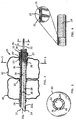
- FIG. 1 is an elevation view, partly schematic, of a laser-resistant surgical ventilation device in accordance with the present invention.
- FIG. 2 is an enlarged elevation view, partly schematic and in partial cross-section, of the laser-resistant double-cuffed distal end of the surgical ventilation device shown in FIG. 1.
- FIG. 3 is a cross-sectional view along line 3-3 of FIG. 2.
- FIG. 4 is a perspective view in partial cross-section and with a portion enlarged of a segment of a metal tube of a surgical ventilating device according to one embodiment of the invention.
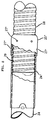
- FIG. 5 is a partly schematic elevation view with portions broken away of a ventilating device according to the invention showing interconnection of tubing elements according to one embodiment.
- FIG. 6 is a cross-sectional view of a connected pair of liquid conduits for inflating elastomeric cuffs of the surgical ventilation device shown in FIG. 1.
- FIG. 7 is an enlarged, partly schematic, elevation view with portions broken away and portions removed, showing interconnection of the lower portions of a ventilating device with a locking ferrule according to a preferred embodiment of the invention.
- FIG. 8 is an enlarged, partly schematic, elevation view with portions broken away and portions in cross-section, showing interconnection of the lower portions of a ventilating device with a locking ferrule according to another embodiment of the invention.
- the endotracheal tube 10 shown in Figs. 1 and 2 is a surgical ventilation device which is resistant to laser-caused dysfunction during laser surgery.
- the device defines a continuous gas passageway 12 for passage of ventilation gases (including anesthetic and respiratory gases) during surgery.
- Endotracheal tube 10 includes a distal end 14 with a beveled tip to facilitate insertion into a human trachea, and defines a portion of the continuous gas passageway 12.
- Endotracheal tube 10 further includes a proximal end 13 for connecting the continuous gas passageway 12 to a source of gas (not shown).
- a flexible metal tube 18 having an airtight wall portion is disposed between the distal end 14 and the proximal end 13 of the endotracheal tube 10.
- the flexible metal tube 18 is resistant to damage by a surgical laser, and as can be seen in Fig. 2, metal tube 18 defines a substantial portion of the continuous gas passageway 12.
- the proximal end 13 of the ventilation device is connected to the metal tube 18 by a proximal polymeric tubing 17 (Fig. 5) disposed over the proximal end of metal tube 18 to form an airtight fit.
- the metal tube 18 is provided with a matte outer surface for dispersing unfocused light when a surgical laser beam is directed against the outer surface of the metal tube 18.
- the matte outer surface helps to prevent inadvertent and unintended damage to a patient's tissues during surgery caused by reflection of a laser beam off of the metal tube 18.
- the airtight metal tube 18 may be of any suitable construction to permit flexibility, such as a helically convoluted metal hose, a segmented flexible metal hose or corrugated bellows, and is characterized by substantial continuity from one end to another so as not to provide laser-penetrable apertures in the sidewall of the metal tube.
- the flexible metal tube 18 is constructed of stainless steel for corrosion resistance.
- the matte exterior finish of the flexible metal tubing reflects a highly unfocused beam, which minimizes the potential of inadvertently damaging tissue.
- metal tube 18 starts out as a thin stainless steel ribbon (i.e., .0035" [0.09mm] thick and .212" [5.4mm] wide).
- This ribbon is fed through a die set to form a helically convoluted hose or tube.
- the die crimps the ribbon 19 back on to itself as shown in Fig. 4.
- ribbon 19 is being formed in the die, a fine metallic filament 21 is fed into an overlapping channel between adjacent crimped ribbon portions.
- Metallic filament 21 has a lower melting temperature than the metallic composition of ribbon 19.
- the formed strip wound metal hose is heat treated in order to melt the metallic filament 21 and thus hermetically seal the seam.
- the ventilating device is airtight along its length from the proximal end 13 thereof to cuffs 20 and 22.
- the sealing and barrier cuffs 20 and 22, respectively, are mounted on the outer surface of a distal polymeric tubing assembly comprised of a tubular polymeric distal tip member 24 and a tubular polymeric sleeve 24'. As shown in Figs. 1 and 2, the sealing cuff 20 is positioned between the barrier cuff 22 and the distal end 14 of the endotracheal tube 10.
- the polymeric portions of the ventilation device may be constructed of any suitable biocompatible material, such as biocompatible polyvinyl chloride, polyurethane, silicone and the like.
- Tip member 24, at the distal end 14 of endotracheal tube 10 is an atraumatic insertion tip including a longitudinal ventilation opening 15a, and advantageously includes a transverse ventilation opening 15b in the event that the longitudinal opening 15a is blocked during use.
- the tip member 24 is received within the polymeric sleeve 24' and attached thereto by any suitable means, such as an ultraviolet (U.V.) light-cured adhesive, chemical weld or glue.
- the polymeric sleeve 24' comprises a proximal end section of the distal polymeric assembly, within which is received the distal end of the metal tube 18, thus connecting the distal end 26 of metal tube 18 with the proximal end section of the lower polymeric tubing assembly.
- a locking ferrule is provided for preventing disengagement of the lower polymeric tubing assembly from the metal tube 18. At least a portion of the locking ferrule is pinched inwardly so as to compress the proximal end section of polymeric sleeve 24' against the metal tube 18.
- the locking ferrule 25 is an annular metal collar that extends around the proximal end section of polymeric sleeve 24'.
- An annular crimp 27 is provided by compressing (i.e., crimping) the locking ferrule on its outside diameter, which reduces the outside diameter of the locking ferrule along the crimp and forms a mechanical bond between the proximal end section of polymeric sleeve 24' and spirals of metal tube 18, thereby preventing disengagement.
- a glue or other adhesive such as U.V. curable adhesive 29 (shown in Fig. 8) can be used to further connect and seal the distal end of metal tube 18 to polymeric sleeve 24'.
- annular crimp 27 discussed above with reference to Figs. 2, 5 and 7 is the preferred embodiment, other embodiments that pinch the locking ferrule inwardly may be used.
- a locking ferrule 25' is disclosed which includes a plurality of inwardly pinched depressions 27' that "stake" the locking ferrule 25' to the metal tube 18 while compressing the proximal end section of sleeve 24' against the metal tube 18 to prevent disengagement therefrom.
- a glue or other adhesive 29 can be used to further connect and seal the distal end of metal tube 18 to sleeve 24'.
- An annular crimp as detailed in Fig. 7 is the preferred embodiment over staking, since the annular crimp has been found to form a stronger mechanical bond and provide a better seal then staking.
- cuffs 20 and 22 are polymeric, and are attached to tip member 24 by any suitable means such as by heat sealing.
- suitable materials for forming the polymeric cuffs include polyvinyl chloride, polyurethane, silicone and the like.
- sealing cuff 20 Means are provided for inflating the sealing cuff 20 to bring the sealing cuff 20 into sealing contact with a patient's trachea and thereby prevent leakage of gas between the sealing cuff 20 and the trachea.
- sealing cuff 20 can be inflated with a gaseous fluid, in the preferred embodiment, sealing cuff 20 is inflated with an aqueous liquid.
- first inflation lumen 28 is provided in the lower polymeric tip member 24, first inflation lumen 28 being in communication with sealing cuff 20 by means of a first port 30 (See Figs. 2 and 3).
- First inflation lumen 28 is connectable with a fluid source for inflation of sealing cuff 20 by means including a first conduit 32.
- First conduit 32 is disposed within metal tube 18 for protection against laser damage during surgery, and connects sealing cuff 20 with a first valve 34 (Fig. 1) for connecting the first conduit 32 with a liquid source (not shown) and for controlling inflation and deflation of sealing cuff 20.
- Means are provided for inflating the barrier cuff 22 with an aqueous liquid for bringing the barrier cuff 22 into contact with a patient's trachea to form a barrier and shield the sealing cuff 20 from damage caused by laser energy directed towards the sealing cuff.
- Barrier cuff 22 shields the sealing cuff 20 from damage by a surgical laser by being positioned between an area of laser surgery (e.g., in an area adjacent metal tube 18) and the fluid-filled sealing cuff 20.
- the barrier cuff 22 is inflated by means including a second inflation lumen 36 in the lower polymeric tip member 24.
- the second inflation lumen 36 is in communication with the barrier cuff 22 through a second port 38.
- the second inflation lumen 36 is connectable with a second liquid source for inflation of barrier cuff 22 by means including a second conduit 40 disposed within metal tube 18 for protection against laser damage.
- the second conduit 40 connects the second inflation lumen 36 with a second valve 41 (Fig. 1) in communication with a liquid source (not shown) for controlling inflation and deflation of barrier cuff 22.
- the first and second conduits 32 and 40 exit metal tube 18 through a standard 15 mm connector 16 for connecting to a source of gas.
- the connector 16 can be constructed of rigid or semi-rigid biocompatible polymeric materials such as PVC and ABS.
- the connector 16 is attached to metal tube 18 by any suitable means, such as glue or other adhesive. If desired, connector 16 can be attached to metal tube 18 in the same manner as lower polymeric sleeve 24'.
- First and second conduits 32 and 40 are adhered together as shown in Fig. 6 by means of a solvent or by extruding them as one piece. This, along with the orientation of first and second inflation lumens 28 and 36, allows easy passage of suctions and stylets through gas passageway 12. First and second conduits 32 and 40 exit through a port in connector 16. They are anchored in this port by means such as glue.
- the proximal end 18a and distal end 18b of metal tube 18 are partially deconvoluted.
- the increase in distance between convolutions of metal tube 18 at the proximal end 18a and distal end 18b provides a means for an adhesive to mechanically hold onto the stainless steel tubing.
- the proximal end 18a of the metal tube 18 has adhesive applied to the entire outer diameter thereof and the upper polymeric tubing 17, such as a standard 15mm connector, is slid over the metal tube 18.
- the distal end 18b of metal tube 18 has adhesive applied to the entire outer diameter thereof and lower polymeric sleeve 24' is expanded and placed on the metal tube 18.
- a plastic atraumatic tip including ventilation openings 15a and 15b Fig.
- Locking ferrule 25 is crimped (or staked, if desired) about the proximal end section of polymeric sleeve 24' to prevent disengagement from metal tube 18.
- the cuffs 20 and 22 are fluid filled with sterile isotonic saline solution.
- the sealing cuff 20 is pressurized to maintain a tracheal seal, and the barrier cuff 22 is filled, but advantageously not to the point of creating any substantial pressure (e.g., filled to near atmospheric pressure).
- a single perforation of the barrier cuff 22 by a surgical laser does not result in substantial fluid drainage from barrier cuff 22.
- water is an excellent absorber of the 10.6 ⁇ m wavelength of a carbon dioxide laser such that surface molecules of the water are boiled off and the laser energy dissipated thereby providing further protection for sealing cuff 20.
- the water in the barrier cuff 22 also eliminates virtually any threat of ignition and burning of the polymeric cuffs.
- the barrier cuff 22 may be filled with a colored aqueous solution which will leak out if the barrier cuff 22 is perforated and thereby visually indicate that the barrier cuff 22 has been perforated.
- a suitable dye for coloring the aqueous solution is methylene blue. Other types of dyes may also be used.
- the present invention provides a stable surgical ventilation system which is highly resistant to laser-caused dysfunction during laser surgery.
- the matte-finished flexible metal tube is impenetrable by a surgical laser and reflects a highly out-of-focus beam to preclude inadvertent damage to tissue.
- the locking ferrule prevents disengagement of the metal tube from the lower polymeric tubing carrying the double-cuff system.
- the liquid-filled barrier cuff provides protection to the tracheal sealing cuff against damage by a laser beam impact.
- the double-cuff system allows the user at least one cuff hit that will not cause loss of protection by the barrier cuff and lead to tracheal tube dysfunction. This, along with the very low probability that the cuff will be hit again and the stability of the system resulting from the locking ferrule, provides for safe and effective airway control during laser surgery.
Abstract
Description
- The present invention relates to a device employed for ventilating a patient during surgical use of a laser in a patient's airway.
- Endotracheal tubes for controlling ventilation of a patient during surgery are known in the art. Such devices generally include a tubular body for conveying the ventilation and anesthesia gases to and from a patient's lungs. In order to provide a tight seal with the trachea for controlled ventilation, a balloon or cuff typically is provided near a distal end of the endotracheal tube, the cuff being inflatable from outside the patient by means of an auxiliary conduit. In order to minimize the possibility of damaging a respiratory tract into which a ventilation device is inserted, such devices usually are constructed of flexible polymeric material.
- Laser microlaryngeal surgery is increasingly being employed for treatment of localized laryngeal and tracheal lesions. There are several known types of surgical lasers, including ruby, argon, helium-neon, Nd-YAG and carbon dioxide lasers. However, the carbon dioxide laser appears best for the removal of laryngeal papillomas, polyps, nodules, cysts and the like, since carbon dioxide lasers produce 10.6µm lightwaves which are absorbed by biological tissue, destroying targeted cell membranes and vaporizing cellular contents.
- During laser microlaryngeal surgery, an unobstructed, binocular view of a lesion is provided. This provides advantages over other known types of laryngeal surgery, such as diathermy and cryosurgery, which utilize a probe that may obscure a surgeon's view of the operative field. In addition, lasers provide a relatively bloodless field, and post-operative edema is usually absent because the area treated by laser is sharply defined. Ideally, laser surgery leaves the surrounding tissue totally unaffected, allowing rapid healing with minimal post-operative scarring.
- One consideration of microlaryngeal surgery is that the operative field is shared by the anesthesiologist and the surgeon. This can be addressed by using an endotracheal tube having an outer diameter sufficiently small to permit the surgery to take place while having an inflatable cuff large enough to make a seal. Alternatively, the surgery can occur with no tube in the airway with patient ventilation and anesthetic gas delivery given during interruptions in surgery via a mask.
- There are disadvantages to having no tube in the airway. These include: lack of complete airway control, the possibility of apnea or hypoventilation with secondary cardiac arrychmias, laryngospasm from too light a plane of anesthesia, non-immobilized vocal cords, and exhalation of potent anesthetic gases through the open mouth of the patient making scavenging of these gases difficult.
- Although performing microlaryngeal surgery with no tube in the airway is undesirable for reasons listed above, problems also arise during laser microlaryngeal surgery when employing an endotracheal tube. These problems typically involve damage caused by the laser of one or both of the endotracheal tube and inflatable cuff. Laser damage to the ventilation device may result in loss of airway management, burning of respiratory tissue, and the production of toxic fumes.
- One method which has been proposed to reduce the risk of damaging the endotracheal tube during laser surgery is to wrap the endotracheal tube with metallic tape. However, wrapping a tube in metal tape is time consuming, and rough edges of the tape may abrade and injure the mucosa of the pharynx and larynx. In the event of a poor wrapping job, the possibility exists that uncovered areas can be ignited, as does the possibility that loose pieces of tape can be aspirated. Wrapped metal tape increases the possibility of a kink developing in the tube, and inadvertent mucosal damage may occur due to reflection of the laser beam off the tape.
- Another proposed method for reducing the risk of ignition of an endotracheal tube is to wrap the tube in wet muslin. However, this also is time consuming, and the muslin adds additional bulk to the tube. Additionally, the muslin may dry out and ignite during surgery.
- Yet another proposed method for reducing the risk of ignition of an endotracheal tube is to coat the tube with dental acrylic. However, dental acrylic rigidfies the tube and is not completely impenetrable by surgical lasers. The dental acrylic further adds undesired bulk to the tube and is time consuming to apply.
- Metal tracheal tubes also have been utilized to avoid ignition of the tube during laser surgery, but problems with the use of metal tracheal tubes have been encountered. These problems include tissue damage brought about by insertion of rigid metal tubes, and inadvertent mucosal damage due to reflection of the laser beam off of the metal tube. Metal tracheal tubes typically have large external diameters which precludes their use with pediatric patients and patients with tracheal stenosis, and generally have no inflatable cuff for creating an air-tight seal. Moreover, the currently available flexible metal tracheal tubes typically are constructed such that the wall of the tube is not air tight.
- Venturi ventilation has been employed during laser microlaryngeal surgery, but this may pose problems such as pheumothorax, pneumomediastinum, stomach inflation, aspiration of secretions, complete respiratory obstruction, and dehydration of mucosal surfaces.
- The use of metallically filled polymers for tube construction also has been suggested to reduce the risk of ignition of endotracheal tubes. However, proposed metallically filled polymers provide only minimal resistance to penetration by laser beam impact (especially in O₂/N₂O enriched atmospheres), and are generally quite expensive.
- In EP-A-0277797 there is disclosed a surgical ventilation device which is resistant to laser-caused dysfunction during laser surgery. This has a proximal end for connecting a continuous gas passageway through the device to a source of gas and, at its distal end, lower and upper inflatable cuffs, the lower cuff being intended to prevent leakage of gas between the lower cuff and the airway and the upper cuff being provided to shield the lower cuff from damage caused by laser energy. A flexible metal tube with a matte outer surface extends between the proximal and distal ends of the device. The upper and lower cuffs are mounted on a length of polymeric tubing which is itself received within and glued to a polymeric sleeve. The distal end of the metal tube is also received within and glued to the polymeric sleeve.
- There remains a need in the art for an improved surgical ventilation device which is resistant to laser-caused dysfunction during laser surgery.
- In accordance with the present invention there is provided a surgical ventilation device defining a continuous gas passageway for passage of ventilation gases during surgery, which is resistant to laser-caused dysfunction, the ventilation device comprising:
- a. a distal polymeric tubing assembly including a distal end which comprises a distal end of the ventilation device, which defines a portion of the continuous gas passageway and which is adapted for insertion into a patient's airway, the distal polymeric tubing assembly further including a proximal end section;
- b. a proximal end having means for connecting the ventilation device to a source of gas;
- c. a flexible airtight metal tube defining a substantial portion of the continuous gas passageway and connecting the distal polymeric tubing assembly and the proximal end of the ventilation device, the metal tube being resistant to damage by a surgical laser and having a matte outer surface for dispersing unfocused light when a surgical laser beam is directed against the outer surface, wherein a distal end of the metal tube is received within the proximal end section of the distal polymeric tubing assembly;
- d. an upper liquid-inflatable cuff connected to and disposed along the distal polymeric tubing assembly near the distal end of the ventilation device;
- e. a lower liquid-inflatable cuff connected to and disposed along the distal polymeric tubing assembly near the distal end of the ventilation device, the lower cuff being located between the distal end of the ventilation device and the upper cuff;
- f. means for inflating the lower cuff with liquid for bringing the lower cuff into sealing contact with the patient's airway to prevent leakage of gas between the lower cuff and the airway, the means for inflating the lower cuff including a first conduit disposed within the metal tube to thereby protect the first conduit from laser damage, the first conduit being in contact with the lower cuff and being connectable with a source of liquid for inflating the lower cuff; and
- g. means for inflating the upper cuff with liquid for bringing the upper cuff into contact with the patient's airway and thereby shield the lower cuff from damage caused by laser energy directed toward the lower cuff, the means for inflating the upper cuff including a second conduit disposed within the metal tube to thereby protect the second conduit from laser damage, the second conduit being in contact with the upper cuff and being connectable with a source of liquid for inflating the upper cuff
- The device preferably includes a bevelled distal end, to facilitate insertion into a patient's airway. In the device of the invention a lower, liquid-inflatable polymeric sealing cuff and an upper, liquid-inflatable barrier cuff are connected to an longitudinally disposed along the distal polymeric tubing assembly at the distal end of the device, the lower sealing cuff being situated between the upper barrier cuff and the distal end. The distal polymeric tubing assembly, with the upper barrier and lower sealing cuffs, is connected to the metal tube by a locking ferrule that compresses the polymeric tubing against the metal tube so as to prevent disengagement.
- FIG. 1 is an elevation view, partly schematic, of a laser-resistant surgical ventilation device in accordance with the present invention.
- FIG. 2 is an enlarged elevation view, partly schematic and in partial cross-section, of the laser-resistant double-cuffed distal end of the surgical ventilation device shown in FIG. 1.
- FIG. 3 is a cross-sectional view along line 3-3 of FIG. 2.
- FIG. 4 is a perspective view in partial cross-section and with a portion enlarged of a segment of a metal tube of a surgical ventilating device according to one embodiment of the invention.
- FIG. 5 is a partly schematic elevation view with portions broken away of a ventilating device according to the invention showing interconnection of tubing elements according to one embodiment.
- FIG. 6 is a cross-sectional view of a connected pair of liquid conduits for inflating elastomeric cuffs of the surgical ventilation device shown in FIG. 1.
- FIG. 7 is an enlarged, partly schematic, elevation view with portions broken away and portions removed, showing interconnection of the lower portions of a ventilating device with a locking ferrule according to a preferred embodiment of the invention.
- FIG. 8 is an enlarged, partly schematic, elevation view with portions broken away and portions in cross-section, showing interconnection of the lower portions of a ventilating device with a locking ferrule according to another embodiment of the invention.
- The
endotracheal tube 10 shown in Figs. 1 and 2 is a surgical ventilation device which is resistant to laser-caused dysfunction during laser surgery. The device defines acontinuous gas passageway 12 for passage of ventilation gases (including anesthetic and respiratory gases) during surgery. -
Endotracheal tube 10 includes adistal end 14 with a beveled tip to facilitate insertion into a human trachea, and defines a portion of thecontinuous gas passageway 12. -
Endotracheal tube 10 further includes aproximal end 13 for connecting thecontinuous gas passageway 12 to a source of gas (not shown). - A
flexible metal tube 18 having an airtight wall portion is disposed between thedistal end 14 and theproximal end 13 of theendotracheal tube 10. Theflexible metal tube 18 is resistant to damage by a surgical laser, and as can be seen in Fig. 2,metal tube 18 defines a substantial portion of thecontinuous gas passageway 12. Theproximal end 13 of the ventilation device is connected to themetal tube 18 by a proximal polymeric tubing 17 (Fig. 5) disposed over the proximal end ofmetal tube 18 to form an airtight fit. - The
metal tube 18 is provided with a matte outer surface for dispersing unfocused light when a surgical laser beam is directed against the outer surface of themetal tube 18. The matte outer surface helps to prevent inadvertent and unintended damage to a patient's tissues during surgery caused by reflection of a laser beam off of themetal tube 18. Theairtight metal tube 18 may be of any suitable construction to permit flexibility, such as a helically convoluted metal hose, a segmented flexible metal hose or corrugated bellows, and is characterized by substantial continuity from one end to another so as not to provide laser-penetrable apertures in the sidewall of the metal tube. - Advantageously, the
flexible metal tube 18 is constructed of stainless steel for corrosion resistance. The matte exterior finish of the flexible metal tubing reflects a highly unfocused beam, which minimizes the potential of inadvertently damaging tissue. - One suitable construction for
metal tube 18 is shown in Fig. 4. According to this embodiment,metal tube 18 starts out as a thin stainless steel ribbon (i.e., .0035" [0.09mm] thick and .212" [5.4mm] wide). This ribbon is fed through a die set to form a helically convoluted hose or tube. The die crimps theribbon 19 back on to itself as shown in Fig. 4. At thesame time ribbon 19 is being formed in the die, a finemetallic filament 21 is fed into an overlapping channel between adjacent crimped ribbon portions.Metallic filament 21 has a lower melting temperature than the metallic composition ofribbon 19. The formed strip wound metal hose is heat treated in order to melt themetallic filament 21 and thus hermetically seal the seam. - Referring back to Figs. 1-3, approximate the
distal end 14 ofendotracheal tube 10 is located a lower liquid-inflatableelastomeric sealing cuff 20 with lowerproximal cuff shoulder 21 inverted to reduce the required intratracheal length, and an upper liquid-inflatable barrier cuff 22 with upperproximal cuff shoulder 23 inverted to both reduce the required intratracheal length and to minimize the exposure of polymeric materials. The ventilating device is airtight along its length from theproximal end 13 thereof tocuffs - The sealing and barrier cuffs 20 and 22, respectively, are mounted on the outer surface of a distal polymeric tubing assembly comprised of a tubular polymeric
distal tip member 24 and a tubular polymeric sleeve 24'. As shown in Figs. 1 and 2, thesealing cuff 20 is positioned between thebarrier cuff 22 and thedistal end 14 of theendotracheal tube 10. - The polymeric portions of the ventilation device, including
tip member 24, polymeric sleeve 24' andupper polymeric tubing 17, may be constructed of any suitable biocompatible material, such as biocompatible polyvinyl chloride, polyurethane, silicone and the like. -
Tip member 24, at thedistal end 14 ofendotracheal tube 10 is an atraumatic insertion tip including alongitudinal ventilation opening 15a, and advantageously includes atransverse ventilation opening 15b in the event that thelongitudinal opening 15a is blocked during use. - In the embodiment shown in Figs. 1 and 2, the
tip member 24 is received within the polymeric sleeve 24' and attached thereto by any suitable means, such as an ultraviolet (U.V.) light-cured adhesive, chemical weld or glue. The polymeric sleeve 24' comprises a proximal end section of the distal polymeric assembly, within which is received the distal end of themetal tube 18, thus connecting thedistal end 26 ofmetal tube 18 with the proximal end section of the lower polymeric tubing assembly. - According to the present invention, a locking ferrule is provided for preventing disengagement of the lower polymeric tubing assembly from the
metal tube 18. At least a portion of the locking ferrule is pinched inwardly so as to compress the proximal end section of polymeric sleeve 24' against themetal tube 18. In a preferred embodiment shown in Figs. 2, 5 and 7, the lockingferrule 25 is an annular metal collar that extends around the proximal end section of polymeric sleeve 24'. Anannular crimp 27 is provided by compressing (i.e., crimping) the locking ferrule on its outside diameter, which reduces the outside diameter of the locking ferrule along the crimp and forms a mechanical bond between the proximal end section of polymeric sleeve 24' and spirals ofmetal tube 18, thereby preventing disengagement. A glue or other adhesive such as U.V. curable adhesive 29 (shown in Fig. 8) can be used to further connect and seal the distal end ofmetal tube 18 to polymeric sleeve 24'. - Although the
annular crimp 27 discussed above with reference to Figs. 2, 5 and 7 is the preferred embodiment, other embodiments that pinch the locking ferrule inwardly may be used. For example, in Fig. 8, a locking ferrule 25' is disclosed which includes a plurality of inwardly pinched depressions 27' that "stake" the locking ferrule 25' to themetal tube 18 while compressing the proximal end section of sleeve 24' against themetal tube 18 to prevent disengagement therefrom. As previously discussed, a glue or other adhesive 29 can be used to further connect and seal the distal end ofmetal tube 18 to sleeve 24'. An annular crimp as detailed in Fig. 7 is the preferred embodiment over staking, since the annular crimp has been found to form a stronger mechanical bond and provide a better seal then staking. - In the embodiment shown, cuffs 20 and 22 are polymeric, and are attached to tip
member 24 by any suitable means such as by heat sealing. Suitable materials for forming the polymeric cuffs include polyvinyl chloride, polyurethane, silicone and the like. - Means are provided for inflating the
sealing cuff 20 to bring thesealing cuff 20 into sealing contact with a patient's trachea and thereby prevent leakage of gas between the sealingcuff 20 and the trachea. Although sealingcuff 20 can be inflated with a gaseous fluid, in the preferred embodiment, sealingcuff 20 is inflated with an aqueous liquid. - To effect inflation of sealing
cuff 20, afirst inflation lumen 28 is provided in the lowerpolymeric tip member 24,first inflation lumen 28 being in communication with sealingcuff 20 by means of a first port 30 (See Figs. 2 and 3).First inflation lumen 28 is connectable with a fluid source for inflation of sealingcuff 20 by means including afirst conduit 32.First conduit 32 is disposed withinmetal tube 18 for protection against laser damage during surgery, and connects sealingcuff 20 with a first valve 34 (Fig. 1) for connecting thefirst conduit 32 with a liquid source (not shown) and for controlling inflation and deflation of sealingcuff 20. - Means are provided for inflating the
barrier cuff 22 with an aqueous liquid for bringing thebarrier cuff 22 into contact with a patient's trachea to form a barrier and shield thesealing cuff 20 from damage caused by laser energy directed towards the sealing cuff.Barrier cuff 22 shields thesealing cuff 20 from damage by a surgical laser by being positioned between an area of laser surgery (e.g., in an area adjacent metal tube 18) and the fluid-filledsealing cuff 20. - The
barrier cuff 22 is inflated by means including asecond inflation lumen 36 in the lowerpolymeric tip member 24. Thesecond inflation lumen 36 is in communication with thebarrier cuff 22 through asecond port 38. Thesecond inflation lumen 36 is connectable with a second liquid source for inflation ofbarrier cuff 22 by means including asecond conduit 40 disposed withinmetal tube 18 for protection against laser damage. Thesecond conduit 40 connects thesecond inflation lumen 36 with a second valve 41 (Fig. 1) in communication with a liquid source (not shown) for controlling inflation and deflation ofbarrier cuff 22. - In the embodiment shown in Fig. 1, the first and
second conduits exit metal tube 18 through a standard 15mm connector 16 for connecting to a source of gas. Theconnector 16 can be constructed of rigid or semi-rigid biocompatible polymeric materials such as PVC and ABS. Theconnector 16 is attached tometal tube 18 by any suitable means, such as glue or other adhesive. If desired,connector 16 can be attached tometal tube 18 in the same manner as lower polymeric sleeve 24'. - First and
second conduits second inflation lumens gas passageway 12. First andsecond conduits connector 16. They are anchored in this port by means such as glue. - In the embodiment shown in Fig. 5, the
proximal end 18a anddistal end 18b ofmetal tube 18 are partially deconvoluted. The increase in distance between convolutions ofmetal tube 18 at theproximal end 18a anddistal end 18b provides a means for an adhesive to mechanically hold onto the stainless steel tubing. Theproximal end 18a of themetal tube 18 has adhesive applied to the entire outer diameter thereof and theupper polymeric tubing 17, such as a standard 15mm connector, is slid over themetal tube 18. Thedistal end 18b ofmetal tube 18 has adhesive applied to the entire outer diameter thereof and lower polymeric sleeve 24' is expanded and placed on themetal tube 18. A plastic atraumatic tip includingventilation openings metal tube 18. Lockingferrule 25 is crimped (or staked, if desired) about the proximal end section of polymeric sleeve 24' to prevent disengagement frommetal tube 18. - After
tracheal tube 10 is intubated (i.e., inserted into a patient's trachea), thecuffs sealing cuff 20 is pressurized to maintain a tracheal seal, and thebarrier cuff 22 is filled, but advantageously not to the point of creating any substantial pressure (e.g., filled to near atmospheric pressure). When fluid in thebarrier cuff 22 is at or near atmospheric pressure, a single perforation of thebarrier cuff 22 by a surgical laser does not result in substantial fluid drainage frombarrier cuff 22. - The probability of hitting a cuff during a single laser laryngeal surgery procedure can be determined from Fried, M.D., "A Survey of the Complications of Laser Surgery", Arch. Otolaryngology, 110:31-334 (1984). The probabilities have been calculated as follows:
P (hitting cuff 1 time) = .06173
P (hitting cuff 2 times) = .00381
P (hittingcuff 3 times) = .00024
P (hitting cuff 4 times) = .00001
Since a single laser perforation of thebarrier cuff 22 does not result in a substantial amount of fluid drainage because of maintaining about atmospheric pressure inbarrier cuff 22, it can be seen thatbarrier cuff 22 provides a substantial amount of protection for sealing cuff 2 anddistal end 14 ofendotracheal tube 10. Further, water is an excellent absorber of the 10.6µm wavelength of a carbon dioxide laser such that surface molecules of the water are boiled off and the laser energy dissipated thereby providing further protection for sealingcuff 20. The water in thebarrier cuff 22 also eliminates virtually any threat of ignition and burning of the polymeric cuffs. - According to one embodiment, the
barrier cuff 22 may be filled with a colored aqueous solution which will leak out if thebarrier cuff 22 is perforated and thereby visually indicate that thebarrier cuff 22 has been perforated. An example of a suitable dye for coloring the aqueous solution is methylene blue. Other types of dyes may also be used. - It can be seen that the present invention provides a stable surgical ventilation system which is highly resistant to laser-caused dysfunction during laser surgery. The matte-finished flexible metal tube is impenetrable by a surgical laser and reflects a highly out-of-focus beam to preclude inadvertent damage to tissue. The locking ferrule prevents disengagement of the metal tube from the lower polymeric tubing carrying the double-cuff system. The liquid-filled barrier cuff provides protection to the tracheal sealing cuff against damage by a laser beam impact. The double-cuff system allows the user at least one cuff hit that will not cause loss of protection by the barrier cuff and lead to tracheal tube dysfunction. This, along with the very low probability that the cuff will be hit again and the stability of the system resulting from the locking ferrule, provides for safe and effective airway control during laser surgery.
- Since many modifications, variations and changes in detail may be made to the described embodiments, it is intended that all matter in the foregoing description and shown in the accompanying drawings be interpreted as illustrative and not in a limiting sense.
Claims (11)
- A surgical ventilation device (10) defining a continuous gas passageway (12) for passage of ventilation gases during surgery, which is resistant to laser-caused dysfunction, the ventilation device (10) comprising:a. a distal polymeric tubing assembly (24, 24') including a distal end which comprises a distal end (14) of the ventilation device (10), which defines a portion of the continuous gas passageway (12) and which is adapted for insertion into a patient's airway, the distal polymeric tubing assembly (24, 24') further including a proximal end section;b. a proximal end (13) having means for connecting the ventilation device (10) to a source of gas;c. a flexible airtight metal tube (18) defining a substantial portion of the continuous gas passageway (12) and connecting the distal polymeric tubing assembly (24, 24') and the proximal end (13) of the ventilation device (10), the metal tube (18) being resistant to damage by a surgical laser and having a matte outer surface for dispersing unfocused light when a surgical laser beam is directed against the outer surface, wherein a distal end of the metal tube (18) is received within the proximal end section of the distal polymeric tubing assembly (24, 24');d. an upper liquid-inflatable cuff (22) connected to and disposed along the distal polymeric tubing assembly (24, 24') near the distal end (14) of the ventilation device (10);e. a lower liquid-inflatable cuff (20) connected to and disposed along the distal polymeric tubing assembly (24, 24') near the distal end (14) of the ventilation device (10), the lower cuff (20) being located between the distal end (14) of the ventilation device (10) and the upper cuff (22);f. means for inflating the lower cuff (20) with liquid for bringing the lower cuff (20) into sealing contact with the patient's airway to prevent leakage of gas between the lower cuff (20) and the airway, the means for inflating the lower cuff (20) including a first conduit (32) disposed within the metal tube (18) to thereby protect the first conduit (32) from laser damage, the first conduit (32) being in contact with the lower cuff (20) and being connectable with a source of liquid for inflating the lower cuff (20); andg. means for inflating the upper cuff (22) with liquid for bringing the upper cuff (22) into contact with the patient's airway and thereby shield the lower cuff (20) from damage caused by laser energy directed toward the lower cuff (20), the means for inflating the upper cuff (22) including a second conduit (40) disposed within the metal tube (18) to thereby protect the second conduit (40) from laser damage, the second conduit (40) being in contact with the upper cuff (22) and being connectable with a source of liquid for inflating the upper cuff (22);characterised in that the device further comprises a locking ferrule (25; 25') that extends around the proximal end section of the distal polymeric tubing assembly (24, 24'), wherein at least a portion of the locking ferrule is pinched inward (27; 27') to compress the proximal end section of the distal polymeric tubing assembly (24, 24') against the metal tube (18) and thereby prevent separation of the distal polymeric tubing assembly (24, 24') and the metal tube (18).
- A surgical ventilation device according to claim 1, characterised in that the means for inflating the lower cuff (20) includes; a first inflation lumen (28) disposed within the distal polymeric tubing assembly (24, 24') and communicating with the distal cuff (20) and with the first conduit (32), and a first valve (34) in communication with the first conduit (32) and connecting the first conduit (32) with a liquid source, the first valve (34) being for controlling inflation of the lower cuff (20); and that the means for inflating the upper cuff (22) includes; a second inflation lumen (36) disposed within the distal polymeric tubing assembly (24, 24') and communicating with the upper cuff (22) and with the second conduit (40); and a second valve (41) in communication with the second conduit (40) and connecting the second conduit (40) with a liquid source, the second valve (41) being for controlling the inflation of the upper cuff (22).
- A surgical ventilation device according to claim 1 or claim 2, characterised in that the ventilation device (10) is airtight from the proximal end (13) of the ventilation device (10) to the upper and lower cuffs (22, 20).
- A surgical ventilation device according to any one of claims 1 to 3, characterised in that the locking ferrule (25; 25') is metal.
- A surgical ventilation device according to any one of claims 1 to 4, characterised in that the locking ferrule (25) is crimped into place (27) about the metal tube (18) with the proximal end section of the distal polymeric tubing assembly (24, 24') compressed therebetween.
- A surgical ventilation device according to any one of claims 1 to 4, characterised in that the locking ferrule (25') is staked into place (27') about the metal tube (18) with the proximal end section of the distal polymeric tubing assembly (24, 24') compressed therebetween.
- A surgical ventilation device according to any one of claims 1 to 6, characterised in that an adhesive (29) is disposed between the metal tube (18) and the proximal end section of the distal polymeric tubing assembly (24, 24').
- A surgical ventilation device according to any one of claims 1 to 7, characterised in that the distal polymeric tubing assembly (24, 24') is comprised of a tubular polymeric distal tip member (24) and a tubular polymeric sleeve (24') that connects the tip member (24) to the metal tube (18), the sleeve (24') including the proximal end section of the distal polymeric tubing assembly (24, 24').
- A surgical ventilation device according to any one of claims 1 to 8, characterised in that the metal tube (18) is formed from a material selected from helically convoluted metal hose, segmented flexible metal hose and corrugated bellows.
- A surgical ventilation device according to any one of claims 1 to 9, characterised in that it includes an upper polymeric tubing assembly (17) connecting the proximal end of the ventilation device (10) to the metal tube (18).
- A surgical ventilation device according to any one of claims 1 to 10, characterised in that liquid for filling the upper and lower cuffs (22, 20) is an aqueous liquid.
Priority Applications (1)
| Application Number | Priority Date | Filing Date | Title |
|---|---|---|---|
| AT89912579T ATE101348T1 (en) | 1988-11-03 | 1989-11-01 | LASER RESISTANT VENTILATION DEVICE WITH CONNECTOR SLEEVES. |
Applications Claiming Priority (2)
| Application Number | Priority Date | Filing Date | Title |
|---|---|---|---|
| US266666 | 1988-11-03 | ||
| US07/266,666 US4953548A (en) | 1987-02-02 | 1988-11-03 | Laser resistant ventilating device with locking ferrule |
Publications (2)
| Publication Number | Publication Date |
|---|---|
| EP0441860A1 EP0441860A1 (en) | 1991-08-21 |
| EP0441860B1 true EP0441860B1 (en) | 1994-02-09 |
Family
ID=23015505
Family Applications (1)
| Application Number | Title | Priority Date | Filing Date |
|---|---|---|---|
| EP89912579A Expired - Lifetime EP0441860B1 (en) | 1988-11-03 | 1989-11-01 | Laser resistant ventilating device with locking ferrule |
Country Status (6)
| Country | Link |
|---|---|
| US (1) | US4953548A (en) |
| EP (1) | EP0441860B1 (en) |
| JP (1) | JP2927854B2 (en) |
| AU (1) | AU634729B2 (en) |
| DE (1) | DE68913046T2 (en) |
| WO (1) | WO1990004993A1 (en) |
Families Citing this family (15)
| Publication number | Priority date | Publication date | Assignee | Title |
|---|---|---|---|---|
| KR900005942A (en) * | 1988-10-19 | 1990-05-07 | 원본미기재 | Laser barrier |
| US5103817A (en) * | 1990-07-20 | 1992-04-14 | Xomed-Treace Inc. | Automatic dye dispersant for endotracheal tubes and catheters |
| US5139019A (en) * | 1991-02-26 | 1992-08-18 | Xomed-Treace Inc. | Laser reflective endotracheal device |
| US5311863A (en) * | 1992-06-12 | 1994-05-17 | Sheridan Catheter Corp. | Laser resistant endotracheal tube, tape, material and article |
| US6350266B1 (en) * | 1995-02-02 | 2002-02-26 | Scimed Life Systems, Inc. | Hybrid stone retrieval device |
| US6368328B1 (en) | 1999-09-16 | 2002-04-09 | Scimed Life Systems, Inc. | Laser-resistant medical retrieval device |
| US6776157B2 (en) * | 2001-03-14 | 2004-08-17 | The Regents Of The University Of Michigan | Medical pacifier and method for use thereof |
| GB0302196D0 (en) * | 2003-01-30 | 2003-03-05 | Boc Group Plc | Medical apparatus |
| US8739795B2 (en) * | 2005-02-07 | 2014-06-03 | Securisyn Medical, Llc | Complete airway stabilization system |
| US9814853B2 (en) | 2005-02-07 | 2017-11-14 | Securisyn Medical, Llc | Airway stabilization system |
| DE102005009577A1 (en) * | 2005-02-28 | 2006-08-31 | Tracoe Medical Gmbh | Inhaled air supplying endotracheal/tracheostoma cannula tube or larynx mask comprises coated tube, fluid fillable thin-walled flexible plastic foil cuff arranged to the outside of the tube for sealing the tube against an air conduit wall |
| US20070066961A1 (en) * | 2005-09-21 | 2007-03-22 | Rutter Michael J | Airway balloon dilator |
| US7771446B2 (en) * | 2005-09-21 | 2010-08-10 | Rutter Michael John | Balloon dilator |
| US20080053454A1 (en) * | 2006-09-01 | 2008-03-06 | Nellcor Puritan Bennett Incorporated | Endotracheal tube including a partially inverted cuff collar |
| WO2014052908A1 (en) * | 2012-09-29 | 2014-04-03 | Empire Technology Development Llc | Detecting leakage from an internal surgical site |
Family Cites Families (39)
| Publication number | Priority date | Publication date | Assignee | Title |
|---|---|---|---|---|
| US601591A (en) * | 1898-03-29 | Howard b | ||
| US1889711A (en) * | 1932-11-29 | Extension joint for stove pipes | ||
| US1296222A (en) * | 1918-06-27 | 1919-03-04 | John D Russ | Device for securing couplings to flexible hose. |
| US1398634A (en) * | 1919-06-20 | 1921-11-29 | Eastman Mfg Company | Means and method for connecting tubing of dissimilar materials |
| US2456048A (en) * | 1937-02-01 | 1948-12-14 | Carpenter Container Corp | Sectional container and coupling |
| US2209239A (en) * | 1938-03-15 | 1940-07-23 | Sterzenbach Ralph | Flexible metal pipe |
| US2211008A (en) * | 1940-02-07 | 1940-08-13 | Martin J Goldberg | Hose coupling attaching apparatus |
| US2481730A (en) * | 1945-08-21 | 1949-09-13 | Sherman Mfg Co H B | Hose coupling |
| US3123072A (en) * | 1959-03-09 | 1964-03-03 | Flexible tube coupling- and closing apparatus | |
| US3376060A (en) * | 1964-12-14 | 1968-04-02 | Shinko Wire Co Ltd | Metallic member and joint assembly |
| US3549180A (en) * | 1968-05-16 | 1970-12-22 | Scovill Manufacturing Co | Hose and hose coupling assembly |
| US3884242A (en) * | 1971-03-29 | 1975-05-20 | Mpc Kurgisil | Catheter assembly |
| US3854484A (en) * | 1971-10-22 | 1974-12-17 | R Jackson | Endotracheal tube with liquid fillable cuff |
| US3931822A (en) * | 1974-02-26 | 1976-01-13 | Marici Frank N | Automatic alternating cuff endo tracheal tube inflator |
| US4156428A (en) * | 1974-08-26 | 1979-05-29 | Henkin Melvyn Lane | Tracheal tube with expandable cuff system |
| US4063561A (en) * | 1975-08-25 | 1977-12-20 | The Signal Companies, Inc. | Direction control device for endotracheal tube |
| US4022217A (en) * | 1975-09-15 | 1977-05-10 | Dupaco Incorporated | Cuff configuration for cuff tracheal tubes |
| DE2557459A1 (en) * | 1975-12-19 | 1977-06-30 | Zeppelin Dieter Von | Air duct type catheter of flexible type - has surrounding hose which forms airtight seals at the annular regions of the catheter tube |
| US4091816A (en) * | 1977-01-28 | 1978-05-30 | Elam James O | Double cuffed endotracheal tube |
| US4114656A (en) * | 1977-06-20 | 1978-09-19 | Murray Corporation | Hose assembly |
| DE2828447C2 (en) * | 1978-06-29 | 1980-05-14 | Willy Ruesch Gmbh & Co Kg, 7053 Kernen | Laryngeal tube |
| US4341210A (en) * | 1978-09-15 | 1982-07-27 | Elam James O | Cuffed endotracheal tube and method |
| US4235239A (en) * | 1978-09-15 | 1980-11-25 | Elam James O | Cuffed endotrachael tube and method |
| US4230108A (en) * | 1979-03-13 | 1980-10-28 | Young Sharon L | Apparatus and method for sealing esophageal entrance to trachea above and below |
| US4328983A (en) * | 1979-06-15 | 1982-05-11 | Gibson Jack Edward | Positive seal steel coupling apparatus and method therefor |
| US4324235A (en) * | 1980-03-24 | 1982-04-13 | Beran Anthony V | Endotracheal tube |
| US4310184A (en) * | 1980-04-28 | 1982-01-12 | Pipe Systems, Incorporated | Polyolefin pipe connector sleeve |
| US4377164A (en) * | 1980-08-01 | 1983-03-22 | Future Teck | Surgical ventilating apparatus |
| FR2504014A1 (en) * | 1981-04-17 | 1982-10-22 | Porges | ENDO-TRACHEAL OR TRACHEOTOMIC BALLOON TUBE FOR ANESTHESIA |
| US4357990A (en) * | 1981-06-08 | 1982-11-09 | Ex-Cell-O Corporation | Crimped tube joint-shoulder ribs |
| US4402684A (en) * | 1981-09-16 | 1983-09-06 | The Kendall Company | Cannula with soft tip |
| FR2522504B1 (en) * | 1982-03-05 | 1985-07-12 | Durand Alain | CATHETERIZATION DEVICE FOR USE IN PERFUSIONS IN THE MEDICAL AND VETERINARY FIELDS |
| US4423725A (en) * | 1982-03-31 | 1984-01-03 | Baran Ostap E | Multiple surgical cuff |
| US4489722A (en) * | 1982-09-27 | 1984-12-25 | Medical Engineering Corporation | Laser resistant endotracheal tube |
| JPS59180190A (en) * | 1983-03-26 | 1984-10-13 | 東海ゴム工業株式会社 | Hose joint |
| US4769897A (en) * | 1983-08-25 | 1988-09-13 | Enron Corp. | Method for forming a press-fitted pipe joint |
| US4658812A (en) * | 1984-04-30 | 1987-04-21 | Hatzenbuhler John R | Laser barrier |
| GB8419510D0 (en) * | 1984-07-31 | 1984-09-05 | Smiths Industries Plc | Tracheostomy tube assemblies |
| US4834087A (en) * | 1987-02-02 | 1989-05-30 | Mallinckrodt, Inc. | Laser resistant ventilating device |
-
1988
- 1988-11-03 US US07/266,666 patent/US4953548A/en not_active Expired - Lifetime
-
1989
- 1989-11-01 DE DE89912579T patent/DE68913046T2/en not_active Expired - Fee Related
- 1989-11-01 WO PCT/US1989/004895 patent/WO1990004993A1/en active IP Right Grant
- 1989-11-01 EP EP89912579A patent/EP0441860B1/en not_active Expired - Lifetime
- 1989-11-01 AU AU45166/89A patent/AU634729B2/en not_active Ceased
- 1989-11-01 JP JP1511819A patent/JP2927854B2/en not_active Expired - Fee Related
Also Published As
| Publication number | Publication date |
|---|---|
| AU4516689A (en) | 1990-05-28 |
| JP2927854B2 (en) | 1999-07-28 |
| US4953548A (en) | 1990-09-04 |
| EP0441860A1 (en) | 1991-08-21 |
| DE68913046D1 (en) | 1994-03-24 |
| AU634729B2 (en) | 1993-03-04 |
| JPH04503165A (en) | 1992-06-11 |
| DE68913046T2 (en) | 1994-05-11 |
| WO1990004993A1 (en) | 1990-05-17 |
Similar Documents
| Publication | Publication Date | Title |
|---|---|---|
| EP0277797B1 (en) | Laser-resistant endotracheal tube | |
| EP0441860B1 (en) | Laser resistant ventilating device with locking ferrule | |
| US5623921A (en) | Laryngeal mask airway and method for its use | |
| AU675027B2 (en) | Esophageal-tracheal double lumen airway | |
| US5040531A (en) | Laser resistant ventilating device | |
| AU700088B2 (en) | Pharyngeal airway | |
| CA2101939C (en) | Artificial airway device | |
| EP1418969B1 (en) | System for intubation | |
| CA2056013C (en) | Medico-surgical tubes | |
| US5819727A (en) | Self-illuminating introducer | |
| JP3565866B2 (en) | Artificial respiration | |
| Asai et al. | The distance between the grille of the laryngeal mask airway and the vocal cords: is conventional intubation through the laryngeal mask safe? | |
| JPH0632660B2 (en) | Laser resistant laser surgical tubing | |
| CA2231331A1 (en) | Laryngeal mask | |
| CA2371435A1 (en) | Laryngeal mask adapter | |
| IE922073A1 (en) | Artificial airway device | |
| CN112839563A (en) | Dual function intubation and ventilation supraglottic airway | |
| WO2020118374A1 (en) | A device for maintaining an airway in a patient | |
| CA2001779C (en) | Laser resistant ventilating device with locking ferrule | |
| US20190030271A1 (en) | Device For Securing Airway And Ventilation During Surgery of the Head and Neck | |
| Sinha et al. | Supraglottic airway devices other than laryngeal mask airway and its prototypes | |
| GB2225955A (en) | Pharyngeal airway | |
| CN210698441U (en) | Double-cuff transnasal tracheal intubation and surgical operation tool | |
| Singh et al. | Endotracheal Tube | |
| Jaeger et al. | Specialized endotracheal tubes |
Legal Events
| Date | Code | Title | Description |
|---|---|---|---|
| PUAI | Public reference made under article 153(3) epc to a published international application that has entered the european phase |
Free format text: ORIGINAL CODE: 0009012 |
|
| 17P | Request for examination filed |
Effective date: 19910425 |
|
| AK | Designated contracting states |
Kind code of ref document: A1 Designated state(s): AT BE CH DE FR GB IT LI LU NL SE |
|
| 17Q | First examination report despatched |
Effective date: 19920907 |
|
| GRAA | (expected) grant |
Free format text: ORIGINAL CODE: 0009210 |
|
| AK | Designated contracting states |
Kind code of ref document: B1 Designated state(s): AT BE CH DE FR GB IT LI LU NL SE |
|
| REF | Corresponds to: |
Ref document number: 101348 Country of ref document: AT Date of ref document: 19940215 Kind code of ref document: T |
|
| REF | Corresponds to: |
Ref document number: 68913046 Country of ref document: DE Date of ref document: 19940324 |
|
| ITF | It: translation for a ep patent filed |
Owner name: ST. CONSUL.BREVETTUALE S.R.L. |
|
| ET | Fr: translation filed | ||
| PGFP | Annual fee paid to national office [announced via postgrant information from national office to epo] |
Ref country code: CH Payment date: 19941013 Year of fee payment: 6 |
|
| PGFP | Annual fee paid to national office [announced via postgrant information from national office to epo] |
Ref country code: SE Payment date: 19941014 Year of fee payment: 6 |
|
| PGFP | Annual fee paid to national office [announced via postgrant information from national office to epo] |
Ref country code: AT Payment date: 19941017 Year of fee payment: 6 |
|
| PLBE | No opposition filed within time limit |
Free format text: ORIGINAL CODE: 0009261 |
|
| STAA | Information on the status of an ep patent application or granted ep patent |
Free format text: STATUS: NO OPPOSITION FILED WITHIN TIME LIMIT |
|
| EAL | Se: european patent in force in sweden |
Ref document number: 89912579.3 |
|
| 26N | No opposition filed | ||
| PG25 | Lapsed in a contracting state [announced via postgrant information from national office to epo] |
Ref country code: AT Effective date: 19951101 |
|
| PG25 | Lapsed in a contracting state [announced via postgrant information from national office to epo] |
Ref country code: SE Effective date: 19951102 |
|
| PG25 | Lapsed in a contracting state [announced via postgrant information from national office to epo] |
Ref country code: CH Effective date: 19951130 Ref country code: LI Effective date: 19951130 |
|
| REG | Reference to a national code |
Ref country code: CH Ref legal event code: PL |
|
| EUG | Se: european patent has lapsed |
Ref document number: 89912579.3 |
|
| REG | Reference to a national code |
Ref country code: GB Ref legal event code: IF02 |
|
| PGFP | Annual fee paid to national office [announced via postgrant information from national office to epo] |
Ref country code: LU Payment date: 20071205 Year of fee payment: 19 Ref country code: NL Payment date: 20071124 Year of fee payment: 19 |
|
| PGFP | Annual fee paid to national office [announced via postgrant information from national office to epo] |
Ref country code: IT Payment date: 20071129 Year of fee payment: 19 |
|
| PGFP | Annual fee paid to national office [announced via postgrant information from national office to epo] |
Ref country code: BE Payment date: 20071213 Year of fee payment: 19 |
|
| PGFP | Annual fee paid to national office [announced via postgrant information from national office to epo] |
Ref country code: FR Payment date: 20071119 Year of fee payment: 19 Ref country code: GB Payment date: 20071128 Year of fee payment: 19 |
|
| PGFP | Annual fee paid to national office [announced via postgrant information from national office to epo] |
Ref country code: DE Payment date: 20071221 Year of fee payment: 19 |
|
| BERE | Be: lapsed |
Owner name: *MALLINCKRODT INC. Effective date: 20081130 |
|
| GBPC | Gb: european patent ceased through non-payment of renewal fee |
Effective date: 20081101 |
|
| PG25 | Lapsed in a contracting state [announced via postgrant information from national office to epo] |
Ref country code: NL Free format text: LAPSE BECAUSE OF NON-PAYMENT OF DUE FEES Effective date: 20090601 |
|
| NLV4 | Nl: lapsed or anulled due to non-payment of the annual fee |
Effective date: 20090601 |
|
| PG25 | Lapsed in a contracting state [announced via postgrant information from national office to epo] |
Ref country code: IT Free format text: LAPSE BECAUSE OF NON-PAYMENT OF DUE FEES Effective date: 20081101 |
|
| REG | Reference to a national code |
Ref country code: FR Ref legal event code: ST Effective date: 20090731 |
|
| PG25 | Lapsed in a contracting state [announced via postgrant information from national office to epo] |
Ref country code: BE Free format text: LAPSE BECAUSE OF NON-PAYMENT OF DUE FEES Effective date: 20081130 |
|
| PG25 | Lapsed in a contracting state [announced via postgrant information from national office to epo] |
Ref country code: DE Free format text: LAPSE BECAUSE OF NON-PAYMENT OF DUE FEES Effective date: 20090603 |
|
| PG25 | Lapsed in a contracting state [announced via postgrant information from national office to epo] |
Ref country code: GB Free format text: LAPSE BECAUSE OF NON-PAYMENT OF DUE FEES Effective date: 20081101 |
|
| PG25 | Lapsed in a contracting state [announced via postgrant information from national office to epo] |
Ref country code: LU Free format text: LAPSE BECAUSE OF NON-PAYMENT OF DUE FEES Effective date: 20081101 |
|
| PG25 | Lapsed in a contracting state [announced via postgrant information from national office to epo] |
Ref country code: FR Free format text: LAPSE BECAUSE OF NON-PAYMENT OF DUE FEES Effective date: 20081130 |