EP0437795A1 - Catheter having a super-elastic metallic tube body - Google Patents
Catheter having a super-elastic metallic tube body Download PDFInfo
- Publication number
- EP0437795A1 EP0437795A1 EP90125041A EP90125041A EP0437795A1 EP 0437795 A1 EP0437795 A1 EP 0437795A1 EP 90125041 A EP90125041 A EP 90125041A EP 90125041 A EP90125041 A EP 90125041A EP 0437795 A1 EP0437795 A1 EP 0437795A1
- Authority
- EP
- European Patent Office
- Prior art keywords
- tube
- super
- catheter
- elastic metallic
- body portion
- Prior art date
- Legal status (The legal status is an assumption and is not a legal conclusion. Google has not performed a legal analysis and makes no representation as to the accuracy of the status listed.)
- Granted
Links
- 229920003002 synthetic resin Polymers 0.000 claims description 40
- 239000000057 synthetic resin Substances 0.000 claims description 40
- 229910045601 alloy Inorganic materials 0.000 claims description 22
- 239000000956 alloy Substances 0.000 claims description 22
- 230000005540 biological transmission Effects 0.000 abstract description 9
- 210000004204 blood vessel Anatomy 0.000 description 21
- -1 for example Inorganic materials 0.000 description 21
- 229920005992 thermoplastic resin Polymers 0.000 description 14
- 229920001971 elastomer Polymers 0.000 description 13
- 239000000806 elastomer Substances 0.000 description 13
- 229920001577 copolymer Polymers 0.000 description 12
- 239000004952 Polyamide Substances 0.000 description 11
- 229920002647 polyamide Polymers 0.000 description 11
- 239000005038 ethylene vinyl acetate Substances 0.000 description 10
- 239000000463 material Substances 0.000 description 10
- 229920001200 poly(ethylene-vinyl acetate) Polymers 0.000 description 10
- 229920000098 polyolefin Polymers 0.000 description 10
- 239000004814 polyurethane Substances 0.000 description 10
- 229920002635 polyurethane Polymers 0.000 description 9
- 229920005989 resin Polymers 0.000 description 8
- 239000011347 resin Substances 0.000 description 8
- 239000004698 Polyethylene Substances 0.000 description 7
- 238000002347 injection Methods 0.000 description 7
- 239000007924 injection Substances 0.000 description 7
- 229920000573 polyethylene Polymers 0.000 description 7
- 229920000915 polyvinyl chloride Polymers 0.000 description 7
- 239000004800 polyvinyl chloride Substances 0.000 description 7
- 238000011282 treatment Methods 0.000 description 7
- 229910004337 Ti-Ni Inorganic materials 0.000 description 6
- 229910011209 Ti—Ni Inorganic materials 0.000 description 6
- 210000004369 blood Anatomy 0.000 description 6
- 239000008280 blood Substances 0.000 description 6
- 230000000916 dilatatory effect Effects 0.000 description 6
- KHYBPSFKEHXSLX-UHFFFAOYSA-N iminotitanium Chemical compound [Ti]=N KHYBPSFKEHXSLX-UHFFFAOYSA-N 0.000 description 6
- 229920002338 polyhydroxyethylmethacrylate Polymers 0.000 description 6
- 229920002379 silicone rubber Polymers 0.000 description 6
- 239000004945 silicone rubber Substances 0.000 description 6
- 239000000126 substance Substances 0.000 description 6
- 238000002583 angiography Methods 0.000 description 5
- 239000011248 coating agent Substances 0.000 description 5
- 238000000576 coating method Methods 0.000 description 5
- 239000012530 fluid Substances 0.000 description 5
- 208000031481 Pathologic Constriction Diseases 0.000 description 4
- 230000002785 anti-thrombosis Effects 0.000 description 4
- 239000003146 anticoagulant agent Substances 0.000 description 4
- 229920000728 polyester Polymers 0.000 description 4
- 230000036262 stenosis Effects 0.000 description 4
- 208000037804 stenosis Diseases 0.000 description 4
- NIXOWILDQLNWCW-UHFFFAOYSA-M Acrylate Chemical compound [O-]C(=O)C=C NIXOWILDQLNWCW-UHFFFAOYSA-M 0.000 description 3
- 229910017518 Cu Zn Inorganic materials 0.000 description 3
- 229910017752 Cu-Zn Inorganic materials 0.000 description 3
- 229910017943 Cu—Zn Inorganic materials 0.000 description 3
- 229920002153 Hydroxypropyl cellulose Polymers 0.000 description 3
- 229910003310 Ni-Al Inorganic materials 0.000 description 3
- 239000002202 Polyethylene glycol Substances 0.000 description 3
- 239000004743 Polypropylene Substances 0.000 description 3
- 229910052782 aluminium Inorganic materials 0.000 description 3
- 229910052790 beryllium Inorganic materials 0.000 description 3
- 229920001400 block copolymer Polymers 0.000 description 3
- 239000002872 contrast media Substances 0.000 description 3
- TVZPLCNGKSPOJA-UHFFFAOYSA-N copper zinc Chemical compound [Cu].[Zn] TVZPLCNGKSPOJA-UHFFFAOYSA-N 0.000 description 3
- 229910052733 gallium Inorganic materials 0.000 description 3
- 229920001477 hydrophilic polymer Polymers 0.000 description 3
- 239000001863 hydroxypropyl cellulose Substances 0.000 description 3
- 235000010977 hydroxypropyl cellulose Nutrition 0.000 description 3
- 238000003780 insertion Methods 0.000 description 3
- 230000037431 insertion Effects 0.000 description 3
- 239000000203 mixture Substances 0.000 description 3
- 229910052759 nickel Inorganic materials 0.000 description 3
- 229920002401 polyacrylamide Polymers 0.000 description 3
- 229920001223 polyethylene glycol Polymers 0.000 description 3
- 229920001155 polypropylene Polymers 0.000 description 3
- 229920000036 polyvinylpyrrolidone Polymers 0.000 description 3
- 239000001267 polyvinylpyrrolidone Substances 0.000 description 3
- 235000013855 polyvinylpyrrolidone Nutrition 0.000 description 3
- 229910052710 silicon Inorganic materials 0.000 description 3
- 229910000679 solder Inorganic materials 0.000 description 3
- 229910052718 tin Inorganic materials 0.000 description 3
- 229910052725 zinc Inorganic materials 0.000 description 3
- 235000009854 Cucurbita moschata Nutrition 0.000 description 2
- 240000001980 Cucurbita pepo Species 0.000 description 2
- 235000009852 Cucurbita pepo Nutrition 0.000 description 2
- YCKRFDGAMUMZLT-UHFFFAOYSA-N Fluorine atom Chemical compound [F] YCKRFDGAMUMZLT-UHFFFAOYSA-N 0.000 description 2
- 238000004026 adhesive bonding Methods 0.000 description 2
- 229910052797 bismuth Inorganic materials 0.000 description 2
- 150000001875 compounds Chemical class 0.000 description 2
- 229910052731 fluorine Inorganic materials 0.000 description 2
- 239000011737 fluorine Substances 0.000 description 2
- 230000004927 fusion Effects 0.000 description 2
- 229920000126 latex Polymers 0.000 description 2
- 229910052751 metal Inorganic materials 0.000 description 2
- 239000002184 metal Substances 0.000 description 2
- 210000005259 peripheral blood Anatomy 0.000 description 2
- 239000011886 peripheral blood Substances 0.000 description 2
- 239000004417 polycarbonate Substances 0.000 description 2
- 229920000515 polycarbonate Polymers 0.000 description 2
- 235000020354 squash Nutrition 0.000 description 2
- 229910001220 stainless steel Inorganic materials 0.000 description 2
- 238000005452 bending Methods 0.000 description 1
- 230000017531 blood circulation Effects 0.000 description 1
- 238000004891 communication Methods 0.000 description 1
- PCHJSUWPFVWCPO-UHFFFAOYSA-N gold Chemical compound [Au] PCHJSUWPFVWCPO-UHFFFAOYSA-N 0.000 description 1
- 229910052737 gold Inorganic materials 0.000 description 1
- 239000010931 gold Substances 0.000 description 1
- 230000002401 inhibitory effect Effects 0.000 description 1
- 230000002093 peripheral effect Effects 0.000 description 1
- 229920002492 poly(sulfone) Polymers 0.000 description 1
- 229920006124 polyolefin elastomer Polymers 0.000 description 1
- 229920003225 polyurethane elastomer Polymers 0.000 description 1
- 238000005476 soldering Methods 0.000 description 1
- 238000004804 winding Methods 0.000 description 1
Images


Classifications
-
- A—HUMAN NECESSITIES
- A61—MEDICAL OR VETERINARY SCIENCE; HYGIENE
- A61M—DEVICES FOR INTRODUCING MEDIA INTO, OR ONTO, THE BODY; DEVICES FOR TRANSDUCING BODY MEDIA OR FOR TAKING MEDIA FROM THE BODY; DEVICES FOR PRODUCING OR ENDING SLEEP OR STUPOR
- A61M25/00—Catheters; Hollow probes
- A61M25/10—Balloon catheters
- A61M25/104—Balloon catheters used for angioplasty
-
- A—HUMAN NECESSITIES
- A61—MEDICAL OR VETERINARY SCIENCE; HYGIENE
- A61M—DEVICES FOR INTRODUCING MEDIA INTO, OR ONTO, THE BODY; DEVICES FOR TRANSDUCING BODY MEDIA OR FOR TAKING MEDIA FROM THE BODY; DEVICES FOR PRODUCING OR ENDING SLEEP OR STUPOR
- A61M25/00—Catheters; Hollow probes
- A61M25/0043—Catheters; Hollow probes characterised by structural features
- A61M25/0045—Catheters; Hollow probes characterised by structural features multi-layered, e.g. coated
-
- A—HUMAN NECESSITIES
- A61—MEDICAL OR VETERINARY SCIENCE; HYGIENE
- A61M—DEVICES FOR INTRODUCING MEDIA INTO, OR ONTO, THE BODY; DEVICES FOR TRANSDUCING BODY MEDIA OR FOR TAKING MEDIA FROM THE BODY; DEVICES FOR PRODUCING OR ENDING SLEEP OR STUPOR
- A61M25/00—Catheters; Hollow probes
- A61M2025/0004—Catheters; Hollow probes having two or more concentrically arranged tubes for forming a concentric catheter system
-
- A—HUMAN NECESSITIES
- A61—MEDICAL OR VETERINARY SCIENCE; HYGIENE
- A61M—DEVICES FOR INTRODUCING MEDIA INTO, OR ONTO, THE BODY; DEVICES FOR TRANSDUCING BODY MEDIA OR FOR TAKING MEDIA FROM THE BODY; DEVICES FOR PRODUCING OR ENDING SLEEP OR STUPOR
- A61M25/00—Catheters; Hollow probes
- A61M25/01—Introducing, guiding, advancing, emplacing or holding catheters
- A61M25/06—Body-piercing guide needles or the like
- A61M25/0662—Guide tubes
Abstract
Description
- This invention relates to a catheter, for example, a catheter to be inserted into a blood vessel such as a catheter for angiography or a catheter for dilating a blood vessel.
- A catheter for angiography to be inserted into a blood vessel consisting of a main body formed of a somewhat soft thermoplastic resin and a rigidity imparting member consisting of a metallic braided wire (generally a stainless-steel wire) and disposed around the main body which is for inhibiting kinking or squash of the catheter while maintaining its high flexibility and for improving the torque transmission efficiency has conventionally been designed.
- A catheter equipped with an inflatable member for dilating a stenosis portion in a blood vessel to improve the blood flow on the peripheral side of the stenosis portion which is for use in curing the stenosis portion is disclosed in EPA No. 349640 for example. This catheter comprises an inner tube made of a flexible synthetic resin, an outer tube made of a flexible synthetic resin and disposed coaxially with the inner tube and a foldable and inflatable member having a proximal end portion attached to the outer tube and a distal portion attached to the inner tube, and besides, the inner or outer tube is provided with a rigidity imparting member consisting of a metallic wire (e.g., a stainless-steel wire).
- The rigidity imparting member used in the above catheter can inhibit its kinking or squash and improve its torque transmission efficiency to some extent. However, the catheter as a whole had low rigidity and particularly had a low efficiency of transmitting the pushing force given at its proximal end (pushability) and only an insufficient torque transmission efficiency.
- Catheters are required to be introduced into peripheral blood vessels year by year, catheters which can be introduced into a more peripheral blood vessel has come to be desired.
- However, the above catheter, whose body portion consists of a synthetic resin tube, needs to have a certain wall thickness and therefore necessarily has a large outer diameter. Accordingly, the blood vessel into which the catheter can be introduced is restricted by its outer diameter and the catheter could only be introduced into a blood vessel sufficiently larger than the outer diameter of the catheter.
- The object of the present invention is to provide a novel and improved catheter of the design that has a high efficiency of transmitting the pushing force given at its proximal end (pushability) and a high torque transmission efficiency and furthermore can be made to have a sufficiently thin wall thickness and a smaller diameter.
- According to the present invention, there is provided a catheter comprising a body portion, a distal portion and an internal lumen and at least the body portion includes a super-elastic metallic tube.
- According to the present invention, there is provided a catheter equipped with an inflating member which comprises a body portion which forms an internal lumen and includes a super-elastic metallic tube having openings in a distal portion; a guide portion for guiding the catheter which is attached to distal portion of said body portion; and a deflatable or foldable inflating member which has a tip portion attached to the guide portion or the distal portion of the above body portion and a rear end portion attached to the body portion and communicates with the lumen through the above openings.
- According to the present invention, there is provided a catheter comprising an inner tube which has a body portion, a distal portion and a first lumen whose tip is open; an outer tube which is disposed coaxially with said inner tube, has a body portion, a distal portion and a distal tip recessed by a predetermined distance from a distal tip of the inner tube and forming a second lumen between an inner surface of said outer tube and an outer surface of said inner tube; a deflatable or foldable and inflatable member which has a tip portion attached to the inner tube and a rear end portion attached to the outer tube and communicates with the second lumen near said rear end portion; a first opening disposed at the proximal portion of said inner tube and communicating with the first lumen; and a second opening disposed at the proximal portion of the the outer tube and communicating with the second lumen, wherein at least one of the body portions of the inner and outer tubes includes a super-elastic metallic tube.
- Fig.1 is a partial longitudinal cross section of a catheter according to one preferred embodiment of the present invention.
- Fig.2 is a partial longitudinal cross section of a catheter according to another preferred embodiment of the present invention.
- Fig.3 is a partial longitudinal cross section of a catheter according to another preferred embodiment of the present invention.
- Fig.4 is a partial longitudinal cross section of a catheter according to another preferred embodiment of the present invention.
- Fig.5 is a partial longitudinal cross section of a catheter according to another preferred embodiment of the present invention.
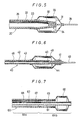
- Fig.6 is a partial longitudinal cross section of a catheter according to another preferred embodiment of the present invention.
- Fig.7 is a partial longitudinal cross section of a catheter according to another preferred embodiment of the present invention.
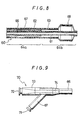
- Fig.8 is a partial longitudinal cross section of a catheter according to another preferred embodiment of the present invention.
- Fig.9 is a view showing the proximal end of a catheter according to one preferred embodiment of the present invention.
- Fig.10 is a view of a catheter according to another preferred embodiment of the present invention.
- The catheter of the present invention will be described according to examples shown in the drawings.
- The catheter generally designated at 1 according to the present invention comprises a
body portion 4a, adistal portion 4b and aninternal lumen 6 and at least thebody portion 4a includes a super-elasticmetallic tube 2. - Therefore, the catheter of the present invention has a high efficiency of transmitting the pushing force given at its proximal end (pushability) and a high torque transmission efficiency and can be made to have a sufficiently thin wall thickness and a smaller diameter.
- A catheter according to one preferred embodiment of the present invention shown in Fig.1 and Fig.10 will be described in the following.
- The
catheter 1 of this preferred embodiment is an example wherein the catheter of the present invention is applied to a catheter for angiography and comprises abody portion 4a, adistal portion 4b, alumen 6 continuous from the proximal end of thecatheter 1 to its distal end, a tip end opening 5 and ahub 7 fixed to the proximal end. - The
body portion 4a comprises a super-elasticmetallic tube 2 and asynthetic resin tube 3 covering the outer surface of the super-elasticmetallic tube 2, and thesynthetic resin tube 3 protrudes from the distal portion of the super-elasticmetallic tube 2 to form thedistal portion 4b of the catheter. - The super-elastic
metallic tube 2 is preferably formed of super-elastic alloys, for example, Ti-Ni alloys containing 49 ~ 58 atom% of Ni, Cu-Zn alloys containing 38.5 ~ 41.5 % by weight of Zn, Cu-Zn-X alloys containing 1 ~10 % by weight of X wherein X is selected from the group consisting of Be, Si, Sn, Al and Ga and Ni-Al alloys containing 36 ~ 38 atom% of Al. The most preferred alloys are Ti-Ni alloys of the above composition. The super-elasticmetallic tube 2 preferably has an outer diameter of 0.3 ~ 6.0 mm, more preferably 0.4 ~ 5.5 mm and a wall thickness of 40 ~ 200 µm, more preferably 50 ~ 150 µm. It preferably has a length of 500 ~ 4,000 mm, more preferably 800 ~ 3,000 mm, a buckling strength (yield stress under load) of 5 ~ 200 kg/mm² at 22°C, more preferably 8 ~ 180 kg/mm² at 22°C, and a restoring stress (yield stress upon unloading) of 3 ~ 180 kg/mm² at 22°C, more preferably 5 ~ 160 kg/mm² at 22°C. It is preferable that the tip of the super-elasticmetallic tube 2 be tapered as shown in Fig.1 in order to prevent the tip from being separated from thesynthetic resin tube 3. It is not necessary that the super-elastic metallic tube have the above outer diameter over its entire length and it is allowed to make its part to have the above outer diameter. - As shown in Fig.1, it is preferable that the
synthetic resin tube 3 cover the entirety of the super-elasticmetallic tube 2 and protrude from the distal portion of the super-elasticmetallic tube 2 to form thedistal portion 4b of the curved catheter. This enables thecatheter 1 of this example to have a flexibledistal portion 4b. The curved portion has a shape suitable for the predetermined blood vessel into which the catheter is to be inserted. - For the
synthetic resin tube 3, thermoplastic resins such as polyolefin elastomer (e.g., polyethylene elastomer, polypropylene elastomer and ethylene-propylene copolymer elastomer), polyvinyl chloride, ethylene-vinyl acetate copolymer, polyamide elastomer, polyurethane and fluorine resin and silicone rubber can be used. It is preferred to use polyamide elastomer or polyurethane. It is preferable that thesynthetic resin tube 3 be sufficiently flexible to allow free kinking of the super-elasticmetallic tube 2. In addition, it is preferred to incorporate a radiopaque substance into the synthetic resin to form thetube 3 because it becomes more easy to locate thecatheter 1 during its introduction into the blood vessel. The radiographically sensitive substance may be a metal such as Ba, W, Bi or a compound thereof in fine powdery form. Thesynthetic resin tube 3 has preferably an outer diameter of the 0.9 ~ 7.0 mm, more preferably 1.0 ~ 6.0 mm and a wall thickness on the outer surface of the super-elasticmetallic tube 2 of 0.04 ~ 0.3 mm, more preferably 0.06 ~ 0.2 mm. - The outer surface of the
synthetic resin tube 3 may be coated with a biocompatible especially antithrombotic resin such as polyhydroxyethyl methacrylate, or hydroxyethyl methacrylate-styrene copolymer (e.g., a HEMA-St-HEMA block copolymer). Particularly, when a material containing a radiopaque substance is used for thesynthetic resin tube 3, it is preferred to perform the above coating in order to remove the roughness of the outer surface due to the radiopaque substance. Although it is preferable that the resin be a biocompatible one, a thin coating of the material used to form thesynthetic resin tube 3 is also allowed. - It is preferred to apply hydrophilic treatment to the outer surface of the
synthetic resin tube 3 in order to make it exhibit lubricity when contacted with blood or the like. Such hydrophilic treatments include coating with hydrophilic polymer such as poly(2-hydroxyethyl methacrylate), polyhydroxyethyl acrylate, hydroxypropyl cellulose, methylvinyl ether-maleic anhydride copolymer, polyethylene glycol, polyacrylamide or polyvinyl pyrrolidone. - It is preferable that the tip of the catheter 1 (tip of the synthetic resin tube 3) have a curved surface such as a semi- spherical surface as shown in Fig.1 in order to prevent any damage to the blood vessel wall and to improve the operability of the
catheter 1. - The hub is fixed to the proximal end of the
body portion 4a shown in Fig.10. Thehub 7 has an opening 8 communicating with thelumen 6 and constituting an injection port for injecting X-ray contrast medium. - The
hub 7 is preferably formed of thermoplastic resins, for example, polycarbonate, polyamide, polysulfine, polyallylate and methacrylate-butylene-styrene copolymer. Instead of providing such hub, an open end of the proximal end of the body portion may constitutes an injection port. - Next, a catheter according to one preferred embodiment of the present invention shown in Fig.2 will be described.
- The
catheter 1 of this preferred embodiment is an example wherein the catheter of the present invention is applied to a catheter for angiography. This catheter comprises abody portion 4a, adistal portion 4b, alumen 6 continuous from the proximal end of thecatheter 1 to its distal tip, a tip end opening 5 and a hub (not shown). Thebody portion 4a and thedistal portion 4b consist of a super-elasticmetallic tube 2 and asynthetic resin layer 3 covering the outer surface of thetube 2. - Those described above can suitably be used for the super-elastic
metallic tube 2. It is preferable that the part of thetube 2 corresponding to thebody portion 4a be highly rigid and the part of thetube 2 corresponding to thedistal portion 4b be more flexible than another portion oftube 2. Such a super-elastic metallic tube can be formed by separately thermally treating the body portion of the super-elasticmetallic tube 2 and its distal portion under different conditions so that the body portion has a large yield stress and the distal portion has a small yield stress and is elastic. - As shown in Fig.3, the outer surface of the distal portion of the super-elastic
metallic tube 2 may be provided with annular grooves in order to make distal portion elastic. The groove is not restricted to annular one and it may be a spiral one. As shown in Fig.4, the distal portion of the super-elasticmetallic tube 2 may have a smaller diameter. As shown in Fig.2, thesynthetic resin layer 3 covers the entirety of the super-elasticmetallic tube 2. For thesynthetic resin layer 3, thermoplastic resins such as polyolefin (e.g., polyethylene, polypropylene and ethylene-propylene copolymer), polyvinyl chloride, ethylene-vinyl acetate copolymer, polyamide elastomer, polyurethane, fluorine resin and silicone rubber can be used. It is preferred to use a polyolefin, a polyamide elastomer or a polyurethane. - It is preferable that the
synthetic resin layer 3 be sufficiently flexible to allow free kinking of the super-elasticmetallic tube 2. In addition, it is preferred to incorporate a radiopaque substance into the synthetic resin to form thetube 3 because it becomes more easy to locate thecatheter 1 during its introduction into the blood vessel. The radiographically sensitive substance may be a metal such as Ba, W, Bi or a compound thereof in fine powdery form. - The
synthetic resin layer 1 preferably has an outer diameter of 0.9 ~ 7.0 mm, more preferably 1.0 ~ 6.0 mm and a wall thickness on the outer surface of the super-elasticmetallic tube 2 of 0.04 ~ 0.3 mm, more preferably 0.06 ~ 0.2 mm. It is preferable that the tip of the catheter (tip of the synthetic resin tube 3) has a curved surface such as a semi-spherical surface in order to prevent any damage to the blood vessel wall and to improve the operability of thecatheter 1. As mentioned above, thesynthetic resin layer 3 may be coated with an antithrombotic resin and hydrophilic treatment may be applied to the outer surface of thelayer 3 so as to make it exhibit lubricity. - The hub is similarly shown in Fig.10 fixed to a proximal end of the
body portion 4a. The hub has an opening communication with thelumen 6 and constituting an injection port for injecting X-ray contrast medium. - Next, an example wherein the catheter of the present invention is applied to a catheter for dilating a blood vessel shown in Fig.5 will described.
- The
catheter 20 comprises abody portion 24 which forms aninternal lumen 26 and includes a super-elasticmetallic tube 22 having openings 30 in its distal portion; aguide portion 29 for guiding the catheter fixed to the tip of thebody portion 24; and a deflatable or foldable andinflatable member 28 having a rear distal portion attached to theguide portion 29 and a proximal end portion attached to thebody portion 24 and which communicates with thelumen 26 through the preforation 30; and a hub (not shown) fixed the proximal end of thebody portion 24. - The
body portion 24 comprises the super-elasticmetallic tube 22 and asynthetic resin layer 23 covering the outer surface of thetube 22. Although thesynthetic resin layer 23 should not necessarily be provided, it is preferably provided in order to inhibit the adhesion of blood to the surface of the super-elasticmetallic tube 22 and to facilitate the fixation of the inflatable member to be mentioned later. - The super-elastic
metallic tube 22 is preferably formed of super-elastic alloys, for example, such as Ti-Ni alloys containing 49 ~ 58 atom% of Ni, Cu-Zn alloys containing 38.5 ~ 41.5 % by weight of Zn, Cu-Zn-X alloys containing 1 ~ 10 % by weight of X wherein X is selected from the group consisting of Be, Si, Sn, Al and Ga, or Ni-Al alloys containing 36 ~ 38 atom% of Al. The most preferred alloys are Ti-Ni alloys of the above composition. The super-elasticmetallic tube 22 preferably has an outer diameter of 0.2 ~ 5 mm, more preferably 0.3 ~ 4 mm and a wall thickness of 50 ~ 200 µm, more preferably 80 ~ 150 µm. It preferably has a length of 500 ~ 4,000 mm, more preferably 1,000 ~ 3,000 mm, a buckling strength (yield stress under load) of 5 ~ 200 kg/mm² at 22°C , more preferably 8 ~ 150 kg/mm² at 22°C , and a restoring stress (yield stress upon unloading) of 3 ~ 180 kg/mm² at 22°C , more preferably 5 ~ 130kg/mm² at 22°C . - It is preferable that the distal portion of the super-elastic
metallic tube 22 be tapered as shown in Fig.5. The distal portion of thesuper-elastic tube 22 is provided with perforation 30. Thesynthetic resin layer 23 covers the entirety of the super-elasticmetallic tube 22 without closing the perforation 30. For thesynthetic resin layer 23, thermoplastic resin such as polyolefin (e.g., polyethylenes, polypropylene, ethylene-propylene copolymer), polyvinyl chloride, ethylene-vinyl acetate copolymer, polymide elastomer and polyurethane, flourine resin and silicone rubber can be used. It is preferred to use polyolefin, polyamide elastomer or polyurethane. - It is preferable that the
synthetic resin layer 23 be sufficiently elastic to allow free bending of the super-elasticmetallic tube 22. Thesynthetic resin layer 23 preferably has a wall thickness of 5 ~ 300 µm, more preferably 10 ~ 200 µm. - The outer surface of the
synthetic resin layer 23 may be coated with a biocompatible especially antithrombotic resin such as a polyhydroxyethyl methacrylate or hydroxyethyl methacrylate-styrene copolymer (e.g., HEMA-St-HEMA block copolymer). - In a catheter equipped with an inflatable member according to the present invention, it is preferred for facilitating the insertion into a blood vessel and further into a guide catheter to apply hydrophilic treatment to the outer surfaces of the
body portion 24 and theinflatable member 28 which have the possibility of contacting with blood during use so as to make them exhibit lubricity when contacted with blood or the like. - Such hydrophilic treatments include coating with hydrophilic polymers such as poly(2-hydroxyethyl methacrylate), polyhydroxyethyl acrylate, hydroxypropyl cellulose, methylvinyl ether-maleic anhydride copolymer, polyethylene glycol, polyacrylamide or polyvinyl pyrrolidone.
- The
guide portion 29 is fixed to the distal tip of thebody portion 24. It functions as a guide wire for guiding thecatheter 1 to a predetermined site in a blood vessel. As theguide portion 29, a member prepared by winding a thin metallic wire around a super-elastic or elastic metallic wire preferably a super-elastic metallic wire can be used for example. Theguide portion 29 preferably has an outer diameter of 0.2 ~ 1.0 mm and a length of about 2 ~ 150 mm. It preferably has a buckling strength (yield stress under load) of 5 ~ 200 kg/mm² at 22°C , more preferably 8 ~ 150 kg/mm² at 22°C , and a restoring stress (yield stress upon unloading) of 3 ~ 180 kg/mm² at 22°C , more preferably 5 ~ 150 kg/mm² at 22°C . - As shown in Fig.5, the
guide portion 29 has at its rear end portion provided a flange which is inserted into the tip of thebody portion 44 and fixed to it by soldering. A scale wax such as silver solder or gold solder can suitably be used as the solder. Theguide portion 29 may be fixed to the distal tip of the body portion by caulking the tip after inserting the rear end portion of theguide portion 29 into the tip. - The
inflatable member 28 is deflatable or foldable and can be folded around thebody portion 24 and theguide portion 29. At least a part of theinflatable member 28 is an almost circular cylinder with an almost equal diameter so that a structure portion in a blood vessel can easily be expanded and theinflatable member 28 is foldable. The above almost circular cylindrical part may not be a completely circular cylinder and may be a polygonal cylinder. The rear end portion of theinflatable member 28 is liquid-tightly fixed to the distal portion of thebody portion 24 by adhesive bonding or thermal fusion. The tip portion of theinflatable member 28 is similarly liquid-tightly fixed to the distal portion of theguide portion 29. - The
inflatable member 28 forms an inflation space between its inner surface and the outer surface of thebody portion 24. The inflation space communicates with thelumen 26 through the perforation 30 of thebody portion 24. Theinflatable member 28 is preferably formed of a somewhat flexible material and for the material, for example, thermoplastic resins including polyolefin such as polyethylene, polypropylene, and ethylene-propylene copolymer, polyvinyl chloride, polyester, ethylene-vinyl acetate copolymer, cross-linked ethylene-vinyl acetate copolymer, polyamide elastomer and polyurethane, silicone rubber and latex rubber can be used. The above thermoplastic resins are preferred and cross-linked ethylene-vinyl acetate copolymer is more preferred. - The front and the back parts of the
inflatable member 28 between its cylindrical part and its fixed tip portion and rear end portion are tapered. Theinflatable member 28 during its inflation preferably has an outer diameter of the cylindrical part of 1.20 ~ 35.00 mm, more preferably 1.50 ~ 30.00 mm, a length of the cylindrical part of 10.00 ~ 80.00 mm, more preferably 15.00 ~ 75.00 mm and a total length of 15.00 ~ 120.00 mm, more preferably 20.00 ~ 100.00 mm. - The hub is similarly shown in Fig.10 fixed to a proximal end of the
body portion 24. The hub has an opening communicating with thelumen 26 and constituting an injection post for injecting a fluid for expansion ofinflatable member 28. - Next, an embodiment wherein the catheter of the present invention is applied to a catheter for dilating a blood vessel shown in Fig.6 will be described.
- The
catheter 40 comprises abody portion 44 which forms aninternal lumen 46 and includes a super-elastic metallic tube having perforation 50 in its distal portion; aguide portion 49 for guiding the catheter which is attached to the distal tip of thebody portion 44; and a deflatable or foldable andinflatable member 48 which has a tip portion attached to the distal portion of thebody portion 44 and a rear end portion attached to thebody portion 44 at a position apart from the perforation 50 toward the proximal end and communicates with thelumen 46 through the perforation 50; and a hub (not shown) fixed to the proximal end of thebody portion 44. - The
catheter 40 of this embodiment is different from thecatheter 20 of the above embodiment shown in Fig.5 in the position at which the tip portion of theinflatable member 48 is fixed and in the shape of thebody portion 44. It is the same as the catheter shown in Fig.5 and mentioned above in all points other than the above points. - The
body portion 44 of thecatheter 40 has an almost equal thickness over its entire length and the distal portion of thebody portion 44 is not tapered. The rear end portion of theinflatable member 48 is attached to thebody portion 44 at a position apart from the perforation 50 toward the proximal end. The tip portion of theinflatable member 48 is attached to the distal portion of thebody portion 44. The tip portion of theinflatable member 48 completely covers the distal portion of thebody portion 44 and extends to theguide portion 49. This enables the distal tip of thebody portion 44 to be prevented from being exposed and minimizes the damage to the inner wall of a blood vessel during insertion of the catheter into the blood vessel. - The hub is similarly shown in Fig.10 fixed to a proximal end of the
body portion 44. The hub has an opening communicating with thelumen 46 and constituting an injection port for injecting a fluid for expansion ofinflatable member 48. - Next, an embodiment wherein the catheter of the present invention is applied to a catheter for dilating a blood vessel shown in Fig.7 and Fig.9 will be described.
- The
catheter 60 comprises aninner tube 61 having abody portion 64a, aproximal end portion 64b and afirst lumen 66 whose tip is open; anouter tube 63 which is disposed coaxially with theinner tube 61, has abody portion 64a and adistal portion 64a, has a distal tip recessed by a predetermined distance from the distal tip of theinner tube 61 and forms asecond lumen 67 between it and the outer surface of theinner tube 61; a deflatable or foldable andinflatable member 68 which has a tip portion attached to theinner tube 61 and a rear end portion attached to theouter tube 63 and communicates with thesecond lumen 67 near the rear end portion, afirst opening 72 shown in Fig.9 disposed at the proximal end portion of the inner tube and communicating with thefirst lumen 66; and asecond opening 71 shown in Fig.9 disposed at the proximal end portion of theouter tube 63 and communicating with thesecond lumen 67. At least one of theinner tube 61 and theouter tube 63 includes a super-elastic metallic tube. - The
catheter 60 consists of theinner tube 61, theouter tube 63, theinflatable member 68 and abranched hub 70. - The
body portion 64a of theouter tube 63 has a super-elasticmetallic tube 62. Theouter tube 63 covers the outer surface of the super-elasticmetallic tube 62 and protrudes from its distal end to form adistal portion 64b. The super-elasticmetallic tube 62 may extend to the distal end of theouter tube 63. The super-elasticmetallic tube 62 is preferably formed of a super-elastic alloys such as a Ti-Ni alloys containing 49 ~ 58 atom% of Ni, Cu-Zn alloys containing 38.5 ~ 41.5 % by weight of Zn, Cu-Zn-X alloys containing 1 ~ 10 % by weight of X wherein X is selected from the group consisting of Be, Si, Sn, Al and Ga, or Ni-Al alloys containing 36 ~ 38 atom% of Al. The most preferred alloys are Ti-Ni alloys of the above composition. The super-elasticmetallic tube 62 preferably has an outer diameter of 0.6 ~ 2.0 mm, more preferably 0.8 ~ 1.6 mm and a wall thickness of 40 ~ 200 µm, more preferably 50 ~ 150 µm. It preferably has a length of 300 ~ 4,000 mm, more preferably 800 ~ 3,000 mm a buckling strength (yield stress under load) of 5 ~ 200 kg/mm² at 22°C , more preferably 8 ~ 150 kg/mm² at 22°C , and a restoring stress (yield stress upon unloading) of 3 ~ 180 kg/mm² at 22°C , more preferably 5 ~ 130 kg/mm² at 22°C . Theouter tube 63 preferably has an outer diameter of 0.60 ~ 2.00 mm, more preferably 0.80 ~ 1.60 mm and an inner diameter of 0.50 ~ 1.90 mm preferably 0.60 ~ 1.40 mm. The difference between the outer diameter of theinner tube 61 and the inner diameter of theouter tube 63 preferably is 0.05 ~ 0.20 mm, more preferably 0.1 ~ 1.20 mm and the wall thickness of theouter tube 63 is 0.05 ~ 0.75 mm, more preferably 0.1 ~ 0.3mm. - The
outer tube 63 is preferably formed of a somewhat flexible material and for the material, for example, thermoplastic resins such as polyolefin (e.g.,polyethylene, polypropylene, ethylene-propylene copolymer), polyvinyl chloride, polyester, ethylene-vinyl acetate copolymer, polyamide elastomer and polyurethane and silicone rubber can be used. The above thermoplastic resins are preferred and polyolefins are more preferred. - The outer surface of the
outer tube 63 may be coated with a biocompatible especially antithrombotic resin such as polyhydroxyethyl methacrylate or hydroxyethyl methacrylate-styrene copolymer (e.g., a HEMA-St-HEMA block copolymer). - The
inner tube 61 is located inside theouter tube 63 and the distal portion of theinner tube 61 protrudes from theouter tube 63. Theinner tube 62 preferably has an outer diameter of 0.40 ~ 1.60 mm, more preferably 0.50 ~ 1.30 mm and an inner diameter of 0.25 ~ 1.50 mm, more preferably 0.30 ~ 1.10 mm. - The
inner tube 61 is preferably formed of a somewhat flexible material and for the material, for example, thermoplastic resins such as polyolefins (e.g., polyethylene, polypropylene, ethylene-propylene copolymer), polyvinyl chloride, polyester, ethylene-vinyl acetate copolymer, polyamide elastomer and polyurethane can be used. The above thermoplastic resins are preferred and polyolefins are more preferred. - The
second lumen 67 is formed by the outer surface of theinner tube 61 and the inner surface of theouter tube 63. Therefore, thesecond lumen 67 has a sufficient volume. The tip of thesecond lumen 67 communicates with the internal space of theinflatable member 68 and the proximal end of thesecond lumen 67 communicates with thesecond opening 71 shown in Fig.9 which forms an injection port for injecting a fluid (e.g., a contrast medium for angiography) for dilating theinflatable member 68. Thesecond opening 71 is formed in thebranched hub 70 shown in Fig.9. - A super-elastic metallic tube may not be disposed on the
outer tube 63 as in the catheter shown in Fig.7 and, as s 8, theinner tube 61 may be provided with the super-elasticmetallic tube 62. In such a case, the super-elasticmetallic tube 62 may be disposed on the outer surface of the inner tube. - The
inflatable member 68 is deflatable or foldable and can be folded around theinner tube 61. At least a part of theinflatable member 68 is an almost circular cylinder having an almost equal diameter so that a stenosis portion in a blood vessel can easily be dilated and theinflatable member 68 is foldable. The above almost circular cylindrical part may not be a completely circular cylinder and may be a polygonal cylinder. The rear end portion of theinflatable member 68 is liquid-tightly fixed to the distal portion of theouter tube 63 by adhesive bonding or thermal fusion and the tip portion of theinflatable member 68 is similarly liquid-tightly fixed to the distal portion of theinner tube 61. Theinflatable member 68 forms an inflatable space between its inner surface and the outer surface of theinner tube 61. The rear end portion of the expansion space communicates with thesecond lumen 67 over the entire circumference. Therefore, since thesecond lumen 67 has a relatively large volume, the fluid for inflation can easily be injected into theinflatable member 68 through the second lumen. - The
inflatable member 68 is preferably formed of a somewhat flexible material and for the material, for example, thermoplastic resins such as polyolefins (e.g., polyethylene, polypropylene, ethylene-propylene copolymer, ethylene-vinyl acetate copolymer, cross-linked ethlene-vinyl acetate copolymer), polyvinyl chloride, polyester, polyamide elastomer and polyurethane, silicone rubber and latex rubber can be used. The above thermoplastic resins are preferred and cross-linked ethylene-vinyl acetate copolymer are more preferred. Theinflatable member 68 during its inflation preferably has an outer diameter of the cylindrical part of 1.20 ~ 35.00 mm, more preferably 1.50 ~ 30.00 mm, a length of the cylindrical part of 10.00 ~ 80.00 mm, more preferably 15.00 ~ 75.00 mm and a total length of 15.00 ~ 120.00 mm, more preferably 20.00 ~ 100.00 mm. - Furthermore, in the catheter equipped with the inflatable member according to the present invention, it is preferred for facilitating the insertion into a blood vessel and further into a guide catheter to be mentioned later to apply hydrophilic treatment to areas having the possibility of contacting with blood during use, that is to say, the outer surface of the
outer tube 63 and the outer surface of theinflatable member 68 so as to make them exhibit lubricity when contacted with blood or the like. Such hydrophilic treatments include coating with a hydrophilic polymer such as poly(2-hydroxyethyl methacrylate), polyhydroxyethyl acrylate, hydroxypropyl cellulose, methylvinyl ether-maleic anhydride copolymer, polyethylene glycol, polyacrylamide or polyvinyl pyrrolidone. - The
branched hub 70 consists of aninner tube hub 73 which has thefirst opening 72 communicating with thefirst lumen 66 and constituting a guide wire port and is fixed to theinner tube 61 and anouter tube hub 74 which has thesecond opening 71 communicating with the second lumen and constituting an injection port for an inflating fluid and is fixed to theouter tube 63. Theinner tube hub 73 and theouter tube hub 74 are fixed together. - The
branched hub 70 is preferably formed of a thermoplastic resin such as polycarbonate, polyamide, polysulfone, polyallylate or methacrylate-butylene-styrene copolymer. Instead of providing such abranched hub 70, for example, a tube having a port member forming an opening at the proximal end may be liquid-tightly attached to each of the first and the second lumens. - Since the catheter of the present invention comprises a body portion, a leading edge and an internal lumen and at least the above body portion includes a super-elastic metallic tube, the catheter of the present invention has a high efficiency of transmitting the pushing force given at its proximal end (pushuability) and has a high torque transmission efficiency. Furthermore, since the body portion of the catheter includes a super-elastic metallic tube, the wall thickness of the body portion can be made sufficiently thin and a catheter with a smaller diameter can be formed.
- Since the catheter of the present invention is a catheter equipped with an inflating member which comprises a body portion forming an internal lumen and including a super-elastic metallic tube having openings in its distal portion; a guide portion for guiding the catheter which is attached to the distal tip of said body portion; and a deflatable or foldable inflating member which has a tip portion attached to the above guide portion or the distal portion of the body portion and a rear end portion attached to the body portion and communicates with the lumen through the openings. The catheter of the present invention has a high efficiency of transmitting the pushing force given at its proximal end (pushability) and a high torque transmission efficiency. Furthermore, since the body portion of the catheter includes a super-elastic metallic tube, the wall thickness of the body portion can be made sufficiently thin and a catheter with a smaller diameter can be formed.
- Since the catheter of the present invention comprises an inner tube having a body portion, a distal portion and a first lumen whose tip is open; an outer tube which is disposed coaxially with said inner tube, has a body portion, a distal portion and a distal tip recessed by a predetermined distance from the distal tip of the inner tube and forms a second lumen between it and the outer surface of said inner tube; a deflatable or foldable inflating member which has a tip portion attached to the inner tube and a rear end portion attached to the outer tube and communicates with the second lumen near said rear end portion; a first opening disposed at the proximal end portion of said inner tube and communicating with the above first lumen; and a second opening disposed at the proximal end portion of the above outer tube and communicating with the second lumen and at least one of the body portions of the inner and outer tubes includes a super-elastic metallic tube. The catheter has a high efficiency of transmitting the pushing force given at its proximal end (pushability) and a high torque transmission efficiency. Furthermore, since the body portion of the catheter includes a super-elastic metallic tube, the wall thickness of the body portion can be made sufficiently thin and a catheter with a small diameter can be formed.
Claims (12)
- A catheter comprising a body portion, a distal portion and an internal lumen, in which at least said body portion includes a super-elastic metallic tube.
- A catheter as set forth in claim 1, wherein said body portion comprises said super-elastic metallic tube and a synthetic resin layer covering the surface of said super-elastic metallic tube.
- A catheter as set forth in claim 1, wherein said super-elastic metallic tube extends from a proximal end of said body portion to a distal portion of said body portion.
- A catheter as set forth in claim 3, wherein the distal portion of said super-elastic metallic tube is more flexible than another portion of said super-elastic metallic tube.
- A catheter as set forth in claim 1, wherein said body portion comprises a super-elastic metallic tube and a synthetic resin tube covering the surface of said super-elastic metallic tube and said synthetic resin tube protrudes from a distal tip of said super-elastic metallic tube to form said distal portion of the catheter.
- A catheter equipped with an inflatable member which comprises a body portion which forms an internal lumen and includes a super-elastic metallic tube having an opening in a distal portion; a guide portion for guiding the catheter which is attached to the distal tip of said body portion;
and a deflatable or foldable and inflatable member which has a tip portion attached to said guide portion or a distal portion of said body portion and a proximal portion attached to said body portion and communicates with said lumen through said opening. - A catheter as set forth in claim 6, wherein said guide portion is formed of a super-elastic alloy.
- A catheter as set forth in claim 6 , wherein said body portion comprises said super-elastic metallic tube and a synthetic resin layer covering the surface of said super-elastic metallic tube.
- A catheter which comprises an inner tube having a body portion, a distal portion and a first lumen whose tip is open; an outer tube which is disposed coaxially with said inner tube, has a body portion, a distal portion and a distal tip recessed by a predetermined distance from the distal tip of said inner tube and forms a second lumen between an inner surface of said outer tube and an outer surface of said inner tube; a deflatable or foldable and inflatable member which has a tip portion attached to said inner tube and a rear end portion attached to said outer tube and communicates with the second lumen near said rear end portion; a first opening disposed at a proximal portion of said inner tube and communicating with said first lumen;
and a second opening disposed at the proximal portion of said outer tube and communicating with said second lumen, in which at least one of the body portions of said inner and outer tubes includes a super-elastic metallic tube. - A catheter as set forth in claim 9, wherein said outer tube comprises a super-elastic metallic tube and a synthetic resin layer covering the surface of said super-elastic metallic tube.
- A catheter as set forth in claim 9, wherein said outer tube comprises a super-elastic metallic tube and a synthetic resin tube covering the surface of said super-elastic metallic tube and said synthetic resin tube protrudes from a distal portion of said super-elastic metallic tube to form said distal portion of the outer tube.
- A catheter as set forth in claim 9, wherein said inner tube comprises a super-elastic metallic tube and a synthetic resin tube covering the surface of said super-elastic metallic tube or fixed to an inner surface of said super-elastic metallic tube and said synthetic resin tube protrudes from a distal portion of said super-elastic metallic tube to form the distal portion of the inner tube.
Priority Applications (1)
| Application Number | Priority Date | Filing Date | Title |
|---|---|---|---|
| EP97102049A EP0787504B1 (en) | 1989-12-20 | 1990-12-20 | Catheter |
Applications Claiming Priority (2)
| Application Number | Priority Date | Filing Date | Title |
|---|---|---|---|
| JP330198/89 | 1989-12-20 | ||
| JP1330198A JP2528011B2 (en) | 1989-12-20 | 1989-12-20 | Catheter |
Related Child Applications (2)
| Application Number | Title | Priority Date | Filing Date |
|---|---|---|---|
| EP97102049A Division EP0787504B1 (en) | 1989-12-20 | 1990-12-20 | Catheter |
| EP97102049.0 Division-Into | 1997-02-10 |
Publications (2)
| Publication Number | Publication Date |
|---|---|
| EP0437795A1 true EP0437795A1 (en) | 1991-07-24 |
| EP0437795B1 EP0437795B1 (en) | 1997-10-29 |
Family
ID=18229932
Family Applications (2)
| Application Number | Title | Priority Date | Filing Date |
|---|---|---|---|
| EP90125041A Expired - Lifetime EP0437795B1 (en) | 1989-12-20 | 1990-12-20 | Catheter having a super-elastic metallic tube body |
| EP97102049A Expired - Lifetime EP0787504B1 (en) | 1989-12-20 | 1990-12-20 | Catheter |
Family Applications After (1)
| Application Number | Title | Priority Date | Filing Date |
|---|---|---|---|
| EP97102049A Expired - Lifetime EP0787504B1 (en) | 1989-12-20 | 1990-12-20 | Catheter |
Country Status (6)
| Country | Link |
|---|---|
| US (1) | US5397306A (en) |
| EP (2) | EP0437795B1 (en) |
| JP (1) | JP2528011B2 (en) |
| AU (1) | AU631036B2 (en) |
| CA (1) | CA2032689C (en) |
| DE (2) | DE69031654T2 (en) |
Cited By (13)
| Publication number | Priority date | Publication date | Assignee | Title |
|---|---|---|---|---|
| WO1993017745A1 (en) * | 1992-03-05 | 1993-09-16 | Gerhard Fuhrmann | Flexible metallic catheter |
| EP0608853A2 (en) * | 1993-01-26 | 1994-08-03 | Terumo Kabushiki Kaisha | Vascular dilatation instrument and catheter |
| EP0608854A2 (en) * | 1993-01-26 | 1994-08-03 | Terumo Kabushiki Kaisha | Blood vessel piercing instrument |
| EP0701460A4 (en) * | 1993-06-02 | 1995-06-20 | Target Therapeutics Inc | Variable stiffness balloon catheter |
| EP0688576A1 (en) * | 1994-06-20 | 1995-12-27 | Terumo Kabushiki Kaisha | Vascular catheter |
| US5507766A (en) * | 1993-01-26 | 1996-04-16 | Terumo Kabushiki Kaisha | Vascular dilatation instrument and catheter |
| US5531719A (en) * | 1993-06-29 | 1996-07-02 | Terumo Kabushiki Kaisha | Vascular catheter with helical space |
| WO2000020063A1 (en) * | 1998-10-05 | 2000-04-13 | Kaneka Corporation | Balloon catheter and production method therefor |
| US6312454B1 (en) | 1996-06-13 | 2001-11-06 | Nitinol Devices & Components | Stent assembly |
| US6652508B2 (en) | 2001-11-09 | 2003-11-25 | Scimed Life Systems, Inc. | Intravascular microcatheter having hypotube proximal shaft with transition |
| US8231647B2 (en) | 2001-12-27 | 2012-07-31 | Boston Scientific Scimed, Inc. | Catheter having an improved torque transmitting shaft |
| US9750625B2 (en) | 2008-06-11 | 2017-09-05 | C.R. Bard, Inc. | Catheter delivery device |
| US11931276B2 (en) | 2008-06-11 | 2024-03-19 | C. R. Bard, Inc. | Catheter delivery device |
Families Citing this family (70)
| Publication number | Priority date | Publication date | Assignee | Title |
|---|---|---|---|---|
| JP2557276B2 (en) * | 1990-05-24 | 1996-11-27 | 日本ゼオン株式会社 | Medical tube |
| JP2554950B2 (en) * | 1990-05-31 | 1996-11-20 | テルモ株式会社 | Vasodilator |
| US6482171B1 (en) | 1991-07-16 | 2002-11-19 | Heartport, Inc. | Multi-lumen catheter |
| US5584803A (en) * | 1991-07-16 | 1996-12-17 | Heartport, Inc. | System for cardiac procedures |
| US6224619B1 (en) | 1991-12-17 | 2001-05-01 | Heartport, Inc. | Blood vessel occlusion trocar having size and shape varying insertion body |
| WO1993023106A1 (en) * | 1992-05-11 | 1993-11-25 | Arrow Precision Products, Inc. | Improved biliary catheter |
| US5500180A (en) | 1992-09-30 | 1996-03-19 | C. R. Bard, Inc. | Method of making a distensible dilatation balloon using a block copolymer |
| US5538512A (en) * | 1993-02-25 | 1996-07-23 | Zenzon; Wendy J. | Lubricious flow directed catheter |
| US5546947A (en) * | 1993-09-30 | 1996-08-20 | Terumo Kabushiki Kaisha | Ultrasonic endoprobe |
| US6659977B2 (en) | 1993-10-27 | 2003-12-09 | Schneider (Europe) A.G. | Multilayer interventional catheter |
| US5961765A (en) * | 1994-09-20 | 1999-10-05 | Schneider (Europe) A. G. | Method of making a catheter |
| DK0650740T3 (en) * | 1993-10-27 | 1999-12-20 | Schneider Europ Gmbh | intervention catheter |
| US5718861A (en) * | 1993-12-20 | 1998-02-17 | C. R. Bard, Incorporated | Method of forming intra-aortic balloon catheters |
| US5951941A (en) * | 1994-03-02 | 1999-09-14 | Scimed Life Systems, Inc. | Block copolymer elastomer catheter balloons |
| US5830182A (en) * | 1994-03-02 | 1998-11-03 | Scimed Life Systems, Inc. | Block copolymer elastomer catheter balloons |
| US7163522B1 (en) | 1994-03-02 | 2007-01-16 | Scimed Life Systems, Inc. | Block copolymer elastomer catheter balloons |
| US7108826B2 (en) * | 1994-03-02 | 2006-09-19 | Boston Scientific Scimed, Inc. | High compliance, high strength catheter balloons useful for treatment of gastrointestinal lesions |
| US6171278B1 (en) | 1994-03-02 | 2001-01-09 | Scimed Life Systems, Inc. | Block copolymer elastomer catheter balloons |
| US6146356A (en) * | 1994-03-02 | 2000-11-14 | Scimed Life Systems, Inc. | Block copolymer elastomer catheter balloons |
| US6406457B1 (en) * | 1994-03-02 | 2002-06-18 | Scimed Life Systems, Inc. | Block copolymer elastomer catheter balloons |
| DK0748232T4 (en) * | 1994-03-02 | 2009-01-19 | Boston Scient Scimed Inc | Catheter balloons of block copolymer elastomers |
| US5478309A (en) | 1994-05-27 | 1995-12-26 | William P. Sweezer, Jr. | Catheter system and method for providing cardiopulmonary bypass pump support during heart surgery |
| JP3549264B2 (en) * | 1994-10-18 | 2004-08-04 | テルモ株式会社 | Catheter tube |
| US5549552A (en) * | 1995-03-02 | 1996-08-27 | Scimed Life Systems, Inc. | Balloon dilation catheter with improved pushability, trackability and crossability |
| US5578010A (en) * | 1995-03-31 | 1996-11-26 | Applied Medical Resources Corporation | Multiple lumen catheter and method of construction |
| DE69633011T2 (en) | 1995-05-24 | 2004-12-09 | Schneider (Usa) Inc., Plymouth | POLYESTERETHERAMIDECOPOLYMER CONTAINING DILATION BALLOONS |
| JPH11506369A (en) * | 1995-06-01 | 1999-06-08 | サイムド ライフ システム インコーポレイテッド | Liquid flow propulsion catheter |
| EP0861105B1 (en) * | 1995-11-13 | 2004-01-28 | Boston Scientific Corporation | Intra-aortic balloon catheter |
| ES2188687T5 (en) | 1996-04-26 | 2011-10-21 | Schneider (Europe) Gmbh | INTERVENTION CATHETER. |
| US5899892A (en) * | 1996-05-31 | 1999-05-04 | Scimed Life Systems, Inc. | Catheter having distal fiber braid |
| US7749585B2 (en) * | 1996-10-08 | 2010-07-06 | Alan Zamore | Reduced profile medical balloon element |
| US5755687A (en) | 1997-04-01 | 1998-05-26 | Heartport, Inc. | Methods and devices for occluding a patient's ascending aorta |
| US6042553A (en) | 1997-04-15 | 2000-03-28 | Symbiosis Corporation | Linear elastic member |
| US6165166A (en) * | 1997-04-25 | 2000-12-26 | Schneider (Usa) Inc. | Trilayer, extruded medical tubing and medical devices incorporating such tubing |
| US6152912A (en) * | 1997-06-10 | 2000-11-28 | Target Therapeutics, Inc. | Optimized high performance spiral-wound vascular catheter |
| US5891110A (en) * | 1997-10-15 | 1999-04-06 | Scimed Life Systems, Inc. | Over-the-wire catheter with improved trackability |
| US6048338A (en) | 1997-10-15 | 2000-04-11 | Scimed Life Systems, Inc. | Catheter with spiral cut transition member |
| US6159178A (en) | 1998-01-23 | 2000-12-12 | Heartport, Inc. | Methods and devices for occluding the ascending aorta and maintaining circulation of oxygenated blood in the patient when the patient's heart is arrested |
| US6113579A (en) | 1998-03-04 | 2000-09-05 | Scimed Life Systems, Inc. | Catheter tip designs and methods for improved stent crossing |
| US6517515B1 (en) | 1998-03-04 | 2003-02-11 | Scimed Life Systems, Inc. | Catheter having variable size guide wire lumen |
| US6287506B1 (en) | 1998-07-09 | 2001-09-11 | Schneider (Usa) Inc. | Method for reducing dilation balloon cone stiffness |
| JP3885382B2 (en) * | 1998-10-05 | 2007-02-21 | 株式会社カネカ | Dilatation catheter |
| US20020007145A1 (en) * | 1998-10-23 | 2002-01-17 | Timothy Stivland | Catheter having improved bonding region |
| US6193705B1 (en) | 1998-10-28 | 2001-02-27 | Scimed Life Systems, Inc. | Flow assisted catheter |
| US6264630B1 (en) * | 1998-12-23 | 2001-07-24 | Scimed Life Systems, Inc. | Balloon catheter having an oscillating tip configuration |
| WO2000066211A1 (en) | 1999-04-30 | 2000-11-09 | Usaminanotechnology, Inc. | Catheter and guide wire |
| WO2001047593A1 (en) * | 1999-12-24 | 2001-07-05 | Toray Industries, Inc. | Catheter with balloon |
| US6623504B2 (en) | 2000-12-08 | 2003-09-23 | Scimed Life Systems, Inc. | Balloon catheter with radiopaque distal tip |
| US6673302B2 (en) * | 2001-01-24 | 2004-01-06 | Scimed Life Systems, Inc. | Wet processing method for catheter balloons |
| US6783511B2 (en) | 2001-04-12 | 2004-08-31 | Heartport, Inc. | Methods and devices for occluding a patient's ascending aorta and delivering oxygenated blood to the patient |
| US7201763B2 (en) * | 2001-10-24 | 2007-04-10 | Boston Scientific Scimed, Inc. | Distal balloon waist material relief and method of manufacture |
| US7670302B2 (en) | 2001-12-18 | 2010-03-02 | Boston Scientific Scimed, Inc. | Super elastic guidewire with shape retention tip |
| US7488304B2 (en) * | 2002-10-08 | 2009-02-10 | Boston Scientific Scimed, Inc. | Covered hypotube to distal port bond |
| CA2522175C (en) * | 2003-04-14 | 2009-07-28 | Cook Incorporated | Large diameter delivery catheter/sheath |
| ATE378085T1 (en) * | 2003-04-28 | 2007-11-15 | Cook Inc | FLEXIBLE INTRODUCER WITH DIFFERENT DUROMETER |
| US8685053B2 (en) * | 2003-05-22 | 2014-04-01 | Boston Scientific Scimed, Inc. | Tether equipped catheter |
| US7367967B2 (en) * | 2003-09-17 | 2008-05-06 | Boston Scientific Scimed, Inc. | Catheter with sheathed hypotube |
| US6994718B2 (en) * | 2003-10-29 | 2006-02-07 | Medtronic Vascular, Inc. | Distal protection device for filtering and occlusion |
| US7105064B2 (en) * | 2003-11-20 | 2006-09-12 | International Flavors & Fragrances Inc. | Particulate fragrance deposition on surfaces and malodour elimination from surfaces |
| US7716801B2 (en) * | 2003-11-24 | 2010-05-18 | Medtronic Vascular, Inc. | Low-profile distal protection device |
| US8382739B2 (en) * | 2003-12-02 | 2013-02-26 | Boston Scientific Scimed, Inc. | Composite medical device and method of forming |
| US7989042B2 (en) * | 2004-11-24 | 2011-08-02 | Boston Scientific Scimed, Inc. | Medical devices with highly flexible coated hypotube |
| US7744574B2 (en) * | 2004-12-16 | 2010-06-29 | Boston Scientific Scimed, Inc. | Catheter tip to reduce wire lock |
| US20070179518A1 (en) * | 2006-02-02 | 2007-08-02 | Becker Bruce B | Balloon Catheters and Methods for Treating Paranasal Sinuses |
| US7985228B2 (en) * | 2006-08-25 | 2011-07-26 | Kyphon Sarl | Apparatus and methods for use of expandable members in surgical applications |
| US8216498B2 (en) | 2008-09-10 | 2012-07-10 | Boston Scientific Scimed, Inc. | Catheter having a coextruded fluoropolymer layer |
| US8926692B2 (en) * | 2010-04-09 | 2015-01-06 | Medtronic, Inc. | Transcatheter prosthetic heart valve delivery device with partial deployment and release features and methods |
| US9144665B2 (en) | 2010-08-09 | 2015-09-29 | Boston Scientific Limited | Flexible sheath assemblies and interventional catheter systems incorporating them |
| WO2015015887A1 (en) * | 2013-07-31 | 2015-02-05 | オリンパスメディカルシステムズ株式会社 | Catheter |
| JP6513369B2 (en) * | 2014-10-24 | 2019-05-15 | 株式会社プラ技研 | CATHETER AND METHOD OF FORMING THE SAME |
Citations (2)
| Publication number | Priority date | Publication date | Assignee | Title |
|---|---|---|---|---|
| EP0279959A1 (en) * | 1987-01-06 | 1988-08-31 | Advanced Cardiovascular Systems, Inc. | Dilatation catheter with thin guide wire |
| WO1989008473A1 (en) * | 1988-03-18 | 1989-09-21 | Boston Scientific Corporation | Dilatation balloon |
Family Cites Families (37)
| Publication number | Priority date | Publication date | Assignee | Title |
|---|---|---|---|---|
| US3566874A (en) * | 1968-08-13 | 1971-03-02 | Nat Patent Dev Corp | Catheter |
| US3736939A (en) * | 1972-01-07 | 1973-06-05 | Kendall & Co | Balloon catheter with soluble tip |
| JPS506192A (en) * | 1973-05-18 | 1975-01-22 | ||
| US3861396A (en) * | 1973-08-08 | 1975-01-21 | Hydro Med Sciences Inc | Drainage tube |
| US3983879A (en) * | 1974-07-25 | 1976-10-05 | Western Acadia, Incorporated | Silicone catheter |
| JPS57148927A (en) * | 1981-03-06 | 1982-09-14 | Olympus Optical Co | Tube for pouring contrast agent |
| US4459318A (en) * | 1981-11-09 | 1984-07-10 | American Hospital Supply Corporation | Method for forming a self-lubricating fill tube |
| US4411655A (en) * | 1981-11-30 | 1983-10-25 | Schreck David M | Apparatus and method for percutaneous catheterization |
| US4665604A (en) * | 1982-02-16 | 1987-05-19 | Cordis Corporation | Non-fused torque control catheter |
| JPS607862A (en) * | 1983-06-27 | 1985-01-16 | テルモ株式会社 | Guide wire for catheter |
| CA1232814A (en) * | 1983-09-16 | 1988-02-16 | Hidetoshi Sakamoto | Guide wire for catheter |
| JPS6063065A (en) * | 1983-09-16 | 1985-04-11 | テルモ株式会社 | Guide wire for catheter |
| CA1246956A (en) * | 1983-10-14 | 1988-12-20 | James Jervis | Shape memory alloys |
| US5055101A (en) * | 1983-10-31 | 1991-10-08 | Catheter Research, Inc. | Variable shape guide apparatus |
| JPS60249788A (en) * | 1984-05-23 | 1985-12-10 | 住友電気工業株式会社 | Flexible pipe |
| DE3442736A1 (en) * | 1984-11-23 | 1986-06-05 | Tassilo Dr.med. 7800 Freiburg Bonzel | DILATATION CATHETER |
| JPS61193670A (en) * | 1985-02-23 | 1986-08-28 | 株式会社トーキン | Catheter |
| US4616653A (en) * | 1985-07-30 | 1986-10-14 | Advanced Cardiovascular Systems, Inc. | Balloon dilatation catheter with advanceable non-removable guide wire |
| US4776844A (en) * | 1986-05-02 | 1988-10-11 | Olympus Optical Co., Ltd. | Medical tube |
| US4739768B2 (en) * | 1986-06-02 | 1995-10-24 | Target Therapeutics Inc | Catheter for guide-wire tracking |
| US4723936A (en) * | 1986-07-22 | 1988-02-09 | Versaflex Delivery Systems Inc. | Steerable catheter |
| JPH01121066A (en) * | 1987-11-05 | 1989-05-12 | Terumo Corp | Catheter having expanded body |
| EP0349640B1 (en) * | 1987-02-27 | 1994-07-13 | Terumo Kabushiki Kaisha | Catheter equipped with expansible member and production thereof |
| US5025799A (en) * | 1987-05-13 | 1991-06-25 | Wilson Bruce C | Steerable memory alloy guide wires |
| US4884557A (en) * | 1987-05-15 | 1989-12-05 | Olympus Optical Co., Ltd. | Endoscope for automatically adjusting an angle with a shape memory alloy |
| JPS6458263A (en) * | 1987-08-28 | 1989-03-06 | Terumo Corp | Intravascular introducing catheter |
| US4953553A (en) * | 1989-05-11 | 1990-09-04 | Advanced Cardiovascular Systems, Inc. | Pressure monitoring guidewire with a flexible distal portion |
| JPH01192369A (en) * | 1988-01-27 | 1989-08-02 | Terumo Corp | Catheter with balloon and its manufacture |
| AU621098B2 (en) * | 1988-01-27 | 1992-03-05 | Advanced Biomedical Devices, Inc. | Steerable guidewire for vascular system |
| US5156594A (en) * | 1990-08-28 | 1992-10-20 | Scimed Life Systems, Inc. | Balloon catheter with distal guide wire lumen |
| US4884573A (en) * | 1988-03-07 | 1989-12-05 | Leocor, Inc. | Very low profile angioplasty balloon catheter with capacity to use steerable, removable guidewire |
| US4884579A (en) * | 1988-04-18 | 1989-12-05 | Target Therapeutics | Catheter guide wire |
| US4998917A (en) * | 1988-05-26 | 1991-03-12 | Advanced Cardiovascular Systems, Inc. | High torque steerable dilatation catheter |
| US4998923A (en) * | 1988-08-11 | 1991-03-12 | Advanced Cardiovascular Systems, Inc. | Steerable dilatation catheter |
| DE68928881T2 (en) * | 1988-10-20 | 1999-05-12 | Terumo Corp | Expandable element catheter and its manufacturing process |
| MY104678A (en) * | 1988-11-10 | 1994-05-31 | Bard Inc C R | Balloon dilatation catheter with integral guidewire. |
| US5019040A (en) * | 1989-08-31 | 1991-05-28 | Koshin Sangyo Kabushiki Kaisha | Catheter |
-
1989
- 1989-12-20 JP JP1330198A patent/JP2528011B2/en not_active Expired - Lifetime
-
1990
- 1990-12-19 CA CA002032689A patent/CA2032689C/en not_active Expired - Lifetime
- 1990-12-19 AU AU68243/90A patent/AU631036B2/en not_active Expired
- 1990-12-20 EP EP90125041A patent/EP0437795B1/en not_active Expired - Lifetime
- 1990-12-20 EP EP97102049A patent/EP0787504B1/en not_active Expired - Lifetime
- 1990-12-20 DE DE69031654T patent/DE69031654T2/en not_active Expired - Lifetime
- 1990-12-20 DE DE69033989T patent/DE69033989T2/en not_active Expired - Lifetime
-
1993
- 1993-11-23 US US08/157,391 patent/US5397306A/en not_active Expired - Lifetime
Patent Citations (2)
| Publication number | Priority date | Publication date | Assignee | Title |
|---|---|---|---|---|
| EP0279959A1 (en) * | 1987-01-06 | 1988-08-31 | Advanced Cardiovascular Systems, Inc. | Dilatation catheter with thin guide wire |
| WO1989008473A1 (en) * | 1988-03-18 | 1989-09-21 | Boston Scientific Corporation | Dilatation balloon |
Cited By (24)
| Publication number | Priority date | Publication date | Assignee | Title |
|---|---|---|---|---|
| WO1993017745A1 (en) * | 1992-03-05 | 1993-09-16 | Gerhard Fuhrmann | Flexible metallic catheter |
| EP0608853A2 (en) * | 1993-01-26 | 1994-08-03 | Terumo Kabushiki Kaisha | Vascular dilatation instrument and catheter |
| EP0608854A2 (en) * | 1993-01-26 | 1994-08-03 | Terumo Kabushiki Kaisha | Blood vessel piercing instrument |
| EP0608854A3 (en) * | 1993-01-26 | 1995-02-22 | Terumo Corp | Blood vessel piercing instrument. |
| EP0608853A3 (en) * | 1993-01-26 | 1995-08-02 | Terumo Corp | Vascular dilatation instrument and catheter. |
| US5507766A (en) * | 1993-01-26 | 1996-04-16 | Terumo Kabushiki Kaisha | Vascular dilatation instrument and catheter |
| US5522832A (en) * | 1993-01-26 | 1996-06-04 | Terumo Kabushiki Kaisha | Blood vessel piercing instrument |
| US5749849A (en) * | 1993-06-02 | 1998-05-12 | Target Therapeutics, Inc. | Variable stiffness balloon catheter |
| EP0701460A4 (en) * | 1993-06-02 | 1995-06-20 | Target Therapeutics Inc | Variable stiffness balloon catheter |
| EP0701460A1 (en) * | 1993-06-02 | 1996-03-20 | Target Therapeutics, Inc. | Variable stiffness balloon catheter |
| US5531719A (en) * | 1993-06-29 | 1996-07-02 | Terumo Kabushiki Kaisha | Vascular catheter with helical space |
| EP0688576A1 (en) * | 1994-06-20 | 1995-12-27 | Terumo Kabushiki Kaisha | Vascular catheter |
| US5569200A (en) * | 1994-06-20 | 1996-10-29 | Terumo Kabushiki Kaisha | Vascular catheter |
| US5782809A (en) * | 1994-06-20 | 1998-07-21 | Terumo Kabushiki Kaisha | Vascular catheter |
| EP0688576B2 (en) † | 1994-06-20 | 2010-12-22 | Terumo Kabushiki Kaisha | Vascular catheter |
| US6312454B1 (en) | 1996-06-13 | 2001-11-06 | Nitinol Devices & Components | Stent assembly |
| WO2000020063A1 (en) * | 1998-10-05 | 2000-04-13 | Kaneka Corporation | Balloon catheter and production method therefor |
| US6613066B1 (en) | 1998-10-05 | 2003-09-02 | Kaneka Corporation | Balloon catheter and production method therefor |
| KR100636338B1 (en) * | 1998-10-05 | 2006-10-18 | 가부시키가이샤 가네가 | Balloon catheter and method for manufacturing same |
| US6652508B2 (en) | 2001-11-09 | 2003-11-25 | Scimed Life Systems, Inc. | Intravascular microcatheter having hypotube proximal shaft with transition |
| US8231647B2 (en) | 2001-12-27 | 2012-07-31 | Boston Scientific Scimed, Inc. | Catheter having an improved torque transmitting shaft |
| US9750625B2 (en) | 2008-06-11 | 2017-09-05 | C.R. Bard, Inc. | Catheter delivery device |
| US11109990B2 (en) | 2008-06-11 | 2021-09-07 | C. R. Bard, Inc. | Catheter delivery device |
| US11931276B2 (en) | 2008-06-11 | 2024-03-19 | C. R. Bard, Inc. | Catheter delivery device |
Also Published As
| Publication number | Publication date |
|---|---|
| EP0787504B1 (en) | 2002-07-17 |
| AU631036B2 (en) | 1992-11-12 |
| DE69033989D1 (en) | 2002-08-22 |
| EP0787504A2 (en) | 1997-08-06 |
| DE69031654D1 (en) | 1997-12-04 |
| DE69031654T2 (en) | 1998-03-19 |
| EP0437795B1 (en) | 1997-10-29 |
| JP2528011B2 (en) | 1996-08-28 |
| DE69033989T2 (en) | 2003-03-13 |
| EP0787504A3 (en) | 1998-10-14 |
| JPH03188875A (en) | 1991-08-16 |
| CA2032689C (en) | 1997-03-25 |
| CA2032689A1 (en) | 1991-06-21 |
| AU6824390A (en) | 1991-08-01 |
| US5397306A (en) | 1995-03-14 |
Similar Documents
| Publication | Publication Date | Title |
|---|---|---|
| US5397306A (en) | Catheter | |
| EP0688576B1 (en) | Vascular catheter | |
| US5662703A (en) | Rolling membrane stent delivery device | |
| EP0608853B1 (en) | Vascular dilatation instrument and catheter | |
| US5300032A (en) | Catheter introducer with flexible tip | |
| US5507766A (en) | Vascular dilatation instrument and catheter | |
| JP3523765B2 (en) | Living organ dilator | |
| US5868719A (en) | Drug delivery balloon catheter device | |
| ES2234243T3 (en) | FLEXIBLE GUIDE CABLE, RESISTANT TO THE CONTOUR, WITH LOW FRICTION, WITH FORMABLE TIP, AND METHOD FOR THEIR ELABORATION. | |
| AU2001245790B2 (en) | Introducer sheath | |
| US8343205B2 (en) | Stent delivery system | |
| JP4033747B2 (en) | Biological organ expansion device | |
| EP0761253B1 (en) | Blood vessel dilator | |
| JP2003527226A (en) | Introduction sheath | |
| JPH08252321A (en) | Treatment tool carrying catheter | |
| JP3699984B2 (en) | Vasodilator and catheter | |
| EP0519515B1 (en) | Blood vessel dilator | |
| JPH0434914B2 (en) | ||
| JPH06225944A (en) | Catheter introducer | |
| JP2001346884A (en) | Guide wire | |
| JPH0492653A (en) | Implement for treating ischemic disease | |
| CA2190903C (en) | Catheter guidable by means of flow | |
| JP2006175241A (en) | Guide wire | |
| JPH07178181A (en) | Catheter introducer | |
| JP2019176978A (en) | Medical long body, medical device, and medical method |
Legal Events
| Date | Code | Title | Description |
|---|---|---|---|
| PUAI | Public reference made under article 153(3) epc to a published international application that has entered the european phase |
Free format text: ORIGINAL CODE: 0009012 |
|
| 17P | Request for examination filed |
Effective date: 19901220 |
|
| AK | Designated contracting states |
Kind code of ref document: A1 Designated state(s): BE DE FR GB IT NL SE |
|
| 17Q | First examination report despatched |
Effective date: 19920403 |
|
| GRAG | Despatch of communication of intention to grant |
Free format text: ORIGINAL CODE: EPIDOS AGRA |
|
| GRAG | Despatch of communication of intention to grant |
Free format text: ORIGINAL CODE: EPIDOS AGRA |
|
| GRAH | Despatch of communication of intention to grant a patent |
Free format text: ORIGINAL CODE: EPIDOS IGRA |
|
| GRAH | Despatch of communication of intention to grant a patent |
Free format text: ORIGINAL CODE: EPIDOS IGRA |
|
| GRAH | Despatch of communication of intention to grant a patent |
Free format text: ORIGINAL CODE: EPIDOS IGRA |
|
| GRAH | Despatch of communication of intention to grant a patent |
Free format text: ORIGINAL CODE: EPIDOS IGRA |
|
| GRAH | Despatch of communication of intention to grant a patent |
Free format text: ORIGINAL CODE: EPIDOS IGRA |
|
| GRAA | (expected) grant |
Free format text: ORIGINAL CODE: 0009210 |
|
| ITF | It: translation for a ep patent filed |
Owner name: FUMERO BREVETTI S.N.C. |
|
| AK | Designated contracting states |
Kind code of ref document: B1 Designated state(s): BE DE FR GB IT NL SE |
|
| DX | Miscellaneous (deleted) | ||
| ET | Fr: translation filed | ||
| REF | Corresponds to: |
Ref document number: 69031654 Country of ref document: DE Date of ref document: 19971204 |
|
| PLBE | No opposition filed within time limit |
Free format text: ORIGINAL CODE: 0009261 |
|
| STAA | Information on the status of an ep patent application or granted ep patent |
Free format text: STATUS: NO OPPOSITION FILED WITHIN TIME LIMIT |
|
| 26N | No opposition filed | ||
| REG | Reference to a national code |
Ref country code: GB Ref legal event code: IF02 |
|
| PGFP | Annual fee paid to national office [announced via postgrant information from national office to epo] |
Ref country code: SE Payment date: 20091207 Year of fee payment: 20 |
|
| PGFP | Annual fee paid to national office [announced via postgrant information from national office to epo] |
Ref country code: NL Payment date: 20091216 Year of fee payment: 20 |
|
| PGFP | Annual fee paid to national office [announced via postgrant information from national office to epo] |
Ref country code: IT Payment date: 20091218 Year of fee payment: 20 Ref country code: FR Payment date: 20091221 Year of fee payment: 20 Ref country code: GB Payment date: 20091216 Year of fee payment: 20 |
|
| PGFP | Annual fee paid to national office [announced via postgrant information from national office to epo] |
Ref country code: BE Payment date: 20091130 Year of fee payment: 20 Ref country code: DE Payment date: 20091217 Year of fee payment: 20 |
|
| REG | Reference to a national code |
Ref country code: NL Ref legal event code: V4 Effective date: 20101220 |
|
| BE20 | Be: patent expired |
Owner name: *TERUMO K.K. Effective date: 20101220 |
|
| REG | Reference to a national code |
Ref country code: GB Ref legal event code: PE20 Expiry date: 20101219 |
|
| EUG | Se: european patent has lapsed | ||
| PG25 | Lapsed in a contracting state [announced via postgrant information from national office to epo] |
Ref country code: GB Free format text: LAPSE BECAUSE OF EXPIRATION OF PROTECTION Effective date: 20101219 Ref country code: NL Free format text: LAPSE BECAUSE OF EXPIRATION OF PROTECTION Effective date: 20101220 |
|
| PG25 | Lapsed in a contracting state [announced via postgrant information from national office to epo] |
Ref country code: DE Free format text: LAPSE BECAUSE OF EXPIRATION OF PROTECTION Effective date: 20101220 |