EP0437344B1 - Microwave oven - Google Patents
Microwave oven Download PDFInfo
- Publication number
- EP0437344B1 EP0437344B1 EP91300136A EP91300136A EP0437344B1 EP 0437344 B1 EP0437344 B1 EP 0437344B1 EP 91300136 A EP91300136 A EP 91300136A EP 91300136 A EP91300136 A EP 91300136A EP 0437344 B1 EP0437344 B1 EP 0437344B1
- Authority
- EP
- European Patent Office
- Prior art keywords
- air
- microwave oven
- container
- oven according
- microwave
- Prior art date
- Legal status (The legal status is an assumption and is not a legal conclusion. Google has not performed a legal analysis and makes no representation as to the accuracy of the status listed.)
- Expired - Lifetime
Links
Images


Classifications
-
- H—ELECTRICITY
- H05—ELECTRIC TECHNIQUES NOT OTHERWISE PROVIDED FOR
- H05B—ELECTRIC HEATING; ELECTRIC LIGHT SOURCES NOT OTHERWISE PROVIDED FOR; CIRCUIT ARRANGEMENTS FOR ELECTRIC LIGHT SOURCES, IN GENERAL
- H05B6/00—Heating by electric, magnetic or electromagnetic fields
- H05B6/64—Heating using microwaves
- H05B6/80—Apparatus for specific applications
- H05B6/808—Microwave heating adapted for vending machines
-
- A—HUMAN NECESSITIES
- A21—BAKING; EDIBLE DOUGHS
- A21B—BAKERS' OVENS; MACHINES OR EQUIPMENT FOR BAKING
- A21B1/00—Bakers' ovens
- A21B1/02—Bakers' ovens characterised by the heating arrangements
- A21B1/24—Ovens heated by media flowing therethrough
- A21B1/245—Ovens heated by media flowing therethrough with a plurality of air nozzles to obtain an impingement effect on the food
-
- B—PERFORMING OPERATIONS; TRANSPORTING
- B65—CONVEYING; PACKING; STORING; HANDLING THIN OR FILAMENTARY MATERIAL
- B65D—CONTAINERS FOR STORAGE OR TRANSPORT OF ARTICLES OR MATERIALS, e.g. BAGS, BARRELS, BOTTLES, BOXES, CANS, CARTONS, CRATES, DRUMS, JARS, TANKS, HOPPERS, FORWARDING CONTAINERS; ACCESSORIES, CLOSURES, OR FITTINGS THEREFOR; PACKAGING ELEMENTS; PACKAGES
- B65D81/00—Containers, packaging elements, or packages, for contents presenting particular transport or storage problems, or adapted to be used for non-packaging purposes after removal of contents
- B65D81/34—Containers, packaging elements, or packages, for contents presenting particular transport or storage problems, or adapted to be used for non-packaging purposes after removal of contents for packaging foodstuffs or other articles intended to be cooked or heated within the package
- B65D81/3446—Containers, packaging elements, or packages, for contents presenting particular transport or storage problems, or adapted to be used for non-packaging purposes after removal of contents for packaging foodstuffs or other articles intended to be cooked or heated within the package specially adapted to be heated by microwaves
- B65D81/3453—Rigid containers, e.g. trays, bottles, boxes, cups
-
- G—PHYSICS
- G07—CHECKING-DEVICES
- G07F—COIN-FREED OR LIKE APPARATUS
- G07F17/00—Coin-freed apparatus for hiring articles; Coin-freed facilities or services
- G07F17/0064—Coin-freed apparatus for hiring articles; Coin-freed facilities or services for processing of food articles
- G07F17/0078—Food articles which need to be processed for dispensing in a hot or cooked condition, e.g. popcorn, nuts
-
- G—PHYSICS
- G07—CHECKING-DEVICES
- G07F—COIN-FREED OR LIKE APPARATUS
- G07F9/00—Details other than those peculiar to special kinds or types of apparatus
- G07F9/10—Casings or parts thereof, e.g. with means for heating or cooling
- G07F9/105—Heating or cooling means, for temperature and humidity control, for the conditioning of articles and their storage
-
- H—ELECTRICITY
- H05—ELECTRIC TECHNIQUES NOT OTHERWISE PROVIDED FOR
- H05B—ELECTRIC HEATING; ELECTRIC LIGHT SOURCES NOT OTHERWISE PROVIDED FOR; CIRCUIT ARRANGEMENTS FOR ELECTRIC LIGHT SOURCES, IN GENERAL
- H05B6/00—Heating by electric, magnetic or electromagnetic fields
- H05B6/64—Heating using microwaves
- H05B6/6408—Supports or covers specially adapted for use in microwave heating apparatus
-
- H—ELECTRICITY
- H05—ELECTRIC TECHNIQUES NOT OTHERWISE PROVIDED FOR
- H05B—ELECTRIC HEATING; ELECTRIC LIGHT SOURCES NOT OTHERWISE PROVIDED FOR; CIRCUIT ARRANGEMENTS FOR ELECTRIC LIGHT SOURCES, IN GENERAL
- H05B6/00—Heating by electric, magnetic or electromagnetic fields
- H05B6/64—Heating using microwaves
- H05B6/647—Aspects related to microwave heating combined with other heating techniques
- H05B6/6473—Aspects related to microwave heating combined with other heating techniques combined with convection heating
- H05B6/6476—Aspects related to microwave heating combined with other heating techniques combined with convection heating the refrigerating air being used for convection
-
- B—PERFORMING OPERATIONS; TRANSPORTING
- B65—CONVEYING; PACKING; STORING; HANDLING THIN OR FILAMENTARY MATERIAL
- B65D—CONTAINERS FOR STORAGE OR TRANSPORT OF ARTICLES OR MATERIALS, e.g. BAGS, BARRELS, BOTTLES, BOXES, CANS, CARTONS, CRATES, DRUMS, JARS, TANKS, HOPPERS, FORWARDING CONTAINERS; ACCESSORIES, CLOSURES, OR FITTINGS THEREFOR; PACKAGING ELEMENTS; PACKAGES
- B65D2581/00—Containers, packaging elements, or packages, for contents presenting particular transport or storage problems, or adapted to be used for non-packaging purposes after removal of contents
- B65D2581/34—Containers, packaging elements, or packages, for contents presenting particular transport or storage problems, or adapted to be used for non-packaging purposes after removal of contents for packaging foodstuffs or other articles intended to be cooked or heated within
- B65D2581/3437—Containers, packaging elements, or packages, for contents presenting particular transport or storage problems, or adapted to be used for non-packaging purposes after removal of contents for packaging foodstuffs or other articles intended to be cooked or heated within specially adapted to be heated by microwaves
- B65D2581/3439—Means for affecting the heating or cooking properties
- B65D2581/3455—Packages having means for improving the internal circulation of air
- B65D2581/3456—Means for holding the contents at a distance from the base of the package, e.g. raised islands or protrusions
-
- Y—GENERAL TAGGING OF NEW TECHNOLOGICAL DEVELOPMENTS; GENERAL TAGGING OF CROSS-SECTIONAL TECHNOLOGIES SPANNING OVER SEVERAL SECTIONS OF THE IPC; TECHNICAL SUBJECTS COVERED BY FORMER USPC CROSS-REFERENCE ART COLLECTIONS [XRACs] AND DIGESTS
- Y10—TECHNICAL SUBJECTS COVERED BY FORMER USPC
- Y10S—TECHNICAL SUBJECTS COVERED BY FORMER USPC CROSS-REFERENCE ART COLLECTIONS [XRACs] AND DIGESTS
- Y10S99/00—Foods and beverages: apparatus
- Y10S99/14—Induction heating
Definitions
- the disclosed invention relates to a hot meal vending device which employs a combination of microwave and convection heating.
- vending machines for dispensing hot and cold drinks, candy, cookies, potato chips and other snack foods have enjoyed significant commercial success.
- vending machines for dispensing meals have been limited to dispensers of refrigerated foods such as sandwiches, salads and the like.
- Vending machines for hot meals generally include a refrigerated compartment for preserving food, a microwave oven compartment for fast cooking, and a conveyor for transferring food from the refrigerated compartment into the microwave oven.
- a refrigerated compartment for preserving food
- a microwave oven compartment for fast cooking
- a conveyor for transferring food from the refrigerated compartment into the microwave oven.
- separate microwave ovens for heating food items removed from a refrigerator are commonly employed in convenience stores, airports, cafeterias and other food vending operations.
- Ovens of the type disclosed in U.S. Patent No. 3,884,213; U.S. Patent No. 4,154,861; U.S. Patent No. 4,289,792; U.S. Patent No. 4,409,453 and U.S. Patent No. 4,835,351 employ air jets which impinge upon the surface of a food product to provide surface heating of the product in combination with microwave heating.
- US-4409453 also discloses means for dividing the interior of an oven cabinet into a cooking chamber and an air heating chamber as required by the pre-characterising part of claim 1 hereinafter.
- Jet impingement ovens have enjoyed significant success in commercial food service and commercial food processing operations. However, a long felt need exists for apparatus for quickly and efficiently heating food products which require little or no preparation for use in a vending machine for hot meals.
- a microwave oven for controlling the temperature and surface texture of a food product
- a cabinet perforated dividing means in said cabinet dividing the interior of the cabinet into a cooking chamber and an air conditioning chamber; air circulating means comprising an impeller in said conditioning chamber to draw air through said perforated dividing means and dispense air from said air conditioning chamber into said cooking chamber; heater means in said air conditioning chamber and microwave heating means communicating with said cooking chamber, said perforated dividing means preventing transfer of microwave energy from said cooking chamber to said air conditioning chamber; characterised in that the heater means is positioned in the air flow between said perforated dividing means and said impeller.
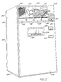
- the numeral 10 generally designates a package which is moved by package handling apparatus 40 into and out of an oven 70 in a vending machine 200.
- a source 90 of electromagnetic radiation and air circulating apparatus 100 are employed for heating a food product 30 selected by a consumer upon depositing the purchase price of the food product in the vending machine 200 illustrated in FIG. 13.
- the vending machine 200 is preferably adapted to serve, for example, hot food products 30 to a customer within about one and a half to two minutes.
- the food products 30 may, for example, include french fried potatoes, chicken nuggets, pizza, and submarine sandwiches.
- the vending machine 200 is mounted in an enclosure cabinet having a back wall 201, spaced side walls 202 and 204, a front panel 205, a top wall 206 and a bottom wall 208.
- the front panel 205 is preferably hingedly secured to side wall 202 and provided with a key actuated lock 210 securing the front panel 205 in a closed and locked position to prevent unauthorized access to the interior of the enclosure.
- a currency receiving mechanism 212 adapted to accept both coins and bills is mounted on front panel 205 along with a coin return slot 214 for returning change to the customer.
- Selector plates 216, 218, 220 and 222 are mounted on the front panel 205 for use by the customer to designate the food item selected to be heated and dispensed through a delivery passage 224 closed by a protective door 225.
- Product identification panels 215, 217, 219 and 221 are associated with selector plates 216, 218, 220 and 222, respectively, to inform the customer what food item can be selected by touching one of the selector plates.
- Identification panel 215 is provided with a graphic illustration of fried potatoes permitting use of the vending machine 200 by persons who do not speak or read a particular language. Additional indicia including words, numerals or other and graphic representations may be applied to each of the panels 215, 217, 219 and 221.
- a condiment holding chamber 209 is provided for holding packets of salt, pepper, sugar, ketchup, mustard and barbecue sauce.
- a refrigerated food storage cabinet 170 is preferably mounted in the lower portion of the interior of the enclosure 200 and package handling apparatus 40 and oven 70 are mounted above and adapted to receive selected packages of food products from the refrigerated storage compartment 170 transported by an elevator 180.
- Each selector plate 216, 218, 220 and 227 is preferably connected to an electrical circuit adapted to initiate a sequence of events provided that payment for the food item 30 has been received in the currency receiving mechanism 212.
- touching selector plate 220 indicates that pizza, graphically illustrated on product identification panel 219 is to be dispensed.
- a container 10 containing pizza will be automatically moved from the refrigerated storage compartment 170 onto an elevator 180 and delivered to the package handling apparatus 40 which will move the package 10 to oven 70 for heating and then dispense the heated product 30 through the delivery passage 224 which is accessible to the customer by raising door 225.
- the electrical circuit controlling the heating of the selected food product 30 preferably includes three programmed elements for delivering a predetermined type of heating for a pre-programmed time interval to the selected food product.
- the programmable circuit preferably includes, for example, devices to program the heating cycle by coordination with the location of the selected food item in the storage compartment 170, a bar code or other readable mechanism on the package, and symbols displayed on or adjacent selector plates 215-221 for the user to touch. From the foregoing, it should be readily apparent that touching one of the selector plates 216, 218, 220 or 222 based on the visual selection of a food item graphically illustrated on product identification panels 215, 217, 219 or 221 initiates a programmed sequence to control the heating cycle of the selected food product 30.
- Package 10 comprises a tubular sleeve 12 having open ends 13a and 13b.
- Sleeve 12 is formed by a top 14, bottom 15 and side walls 16a and 16b having peripheral edges connected to form an interior cavity 17 for a container 18.
- Bottom 15 is narrower than top 14 and sidewalls 16a and 16b are inclined relative to vertical planes.
- Container 18 is an open topped tray formed by side walls 20 and 21 having end walls 22 and 23 secured between opposite ends thereof and a bottom wall 24.
- Support ribs 25 or other suitable projections extend upwardly from bottom wall 24 for supporting a food product 30 spaced from bottom wall 24 to provide space forming a path 28 extending between the lower surface 31 of the food product 30 and the upper surface 25a of the bottom wall 24 of container 18.
- the package 10 carries the food product 30 in the open-top container 18 which is enclosed in the tube-like sleeve 12, preferably constructed of cellulosic or other poorly conductive material.
- the food product 30 is stored in a cabinet 170 in the container 18 inside of the sleeve covers 12.
- the container 18 is withdrawn from the sleeve 12 prior to heating the food product 30 and then the food 30 and container 18 are returned to the sleeve 12 to retain heat in the food until the package 10 is opened by the customer.
- Cabinet 170 may be refrigerated or divided into compartments, some of which are refrigerated depending upon the nature of the food product to be dispensed by the vending machine 200.
- the relatively non-conducting sleeve 12 serves as a comfortable holder for the hot container 18 and food 30.
- the numeral 18a generally designates a modified form of the container having a susceptor belt 27 mounted adjacent bottom 24 of the container having ribs 25 formed thereon.
- the susceptor belt coating 27 is formed of polyethylene terephthalate and is commercially available from a variety of sources including Frigigold of England and is recommended for use in reusable plastic or paperboard microwave cook ware in a recommended temperature range of up to 232°C (450°F).
- the susceptor belt 27 is rapidly heated by microwave energy until it reaches a maximum temperature of, for example, 177°C (350°F) and the temperature level is maintained to provide radiant and conductive bottom heat to the food product 30.
- a layer 29 of a particulate food product such as strips of pasta or slices of potato, is positioned between the bottom wall 24 of container 18 and the lower surface 31 of food product 30.
- layer 29 is slices of potato and product 30 is a meat product
- juices dripping from the lower surface of food product 30 will contact and be absorbed by layer 29 of potato slices to enhance the cooking of both the slices of potato and the meat product 30.
- the liquid juices enhance the flavor and appearance of the potatoes while the circulation of air through passages 28 between the potato slices results in controlled drying and evaporation of moisture from the bottom of the food product 30 to provide an acceptable texture, taste, smell and appearance superior to that conventionally achieved in microwave ovens.
- the food product 30a may comprise particulate material, such as slices of fried potatoes and a corrugated susceptor belt 27 is mounted adjacent bottom 24 to form ribs 25. Since the susceptor belt 27 is controllably heated by the microwave and portions of the upwardly extending ribs 25 contact the lower surface of the food product, the structure simulates grilling as well as allowing juices to flow into the area between the ribs.
- Container 18b illustrated in FIG. 15, is provided with a sheet 27a of a heat shrinkable film bonded to lip 19a for sealing the food product 30a in the container 30b.
- a sheet 27a preferably formed of polymeric compounds and materials, for example, synthetic thermoplastic resins of the type which are commercially available from E.I. DuPont de Nemours and Co. of Wilmington, Delaware, used to form a polyester film which will melt when contacted by air at a temperature of less than 204°C (400°F) which results in film 27a becoming perforated and rolling toward lip 19 which extends around the periphery of container 18b.
- the cohesive nature of the polyester material prevents it from dripping into the food container. It should be readily apparent that the use of the polyester film 27a provides a seal which prevents deterioration of food product 30a over an extended period of time in a refrigerator or freezer.
- a perforated grid or lattice 27b may be mounted between the upper surface of lip 19 and the lower surface of sheet 27a.
- Legs 27c and 27d spanning across the top of container 18b support film 27a to assure that portions of film 27a do not drop downwardly to engage the food product 30a in container 18b.
- film 27a and lattice 27b are bonded or otherwise sealingly secured to the lip 19 which extends around the periphery of the open top of container 18b to prevent dehydration and to otherwise protect food product 30 in container 18b.
- Food product 30 is supported on susceptor belt 27 having upwardly extending projections 25 formed thereon for spacing the lower surface of food product 30 above the bottom of container 18b to form air passages therebetween as hereinbefore described.
- impingement of air stream 28a against the upper surface of film 27a causes a central portion of film 27a to be perforated forming an opening 27a' in a central portion of the film intermediate edges of container 18b.
- opening 27a' is enlarged as heat is transferred to the film 27a which tends to roll back as indicated at 27a" as the film material shrinks and is distorted.
- heat transferred to the film 27a causes the meltable and shrinkable film 27a to retract to the position designated 27a''' thereby uncovering the upper surface of food product 30 in container 18b.
- container 18b is preferably stored in a tubular sleeve 12 of the type hereinbefore described to prevent perforation of sealing film 27a during handling of containers while being transported for stocking storage cabinet 170.
- container 18b is reinserted into the tubular sleeve 12 prior to dispensing the food product to the customer so that the hot container 18b and the food product 30 therein can be handled by the customer to eliminate the necessity for providing "hot pads" or other apparatus for handling the hot container.
- package handling apparatus 40 includes a container loading device 50 and a container unloading device 60.
- the loading device 50 and unloading device 60 are of substantially identical construction and comprise motors 51a and 51b, respectively, drivingly connected through synchronous drive belts 52 to the end of drive screws 56.
- Each drive screw 56 has threads formed on the outer surface thereof which engage internal threads in a drive nut 55 which moves linearly along drive screw 56 as the drive screw rotates. Thrust is transmitted from the drive nut 55 to a transitional tube 57.
- the entire screw 56 and nut 55 assembly is protected from contamination and environmental elements by a cover tube 58, and an end wiper seal 59.
- Rotational thrust bearings 54 allow the screw 56 to freely rotate under loaded conditions.
- the electromechanical linear actuators 50 and 60 are commercially available from Jasta, Inc. of San Jose, California and from Dayton Electric Manufacturing Co. of Chicago, Illinois, and form no part of the invention except in the claimed combination.
- Motors 51a and 51b are preferably variable speed reversible synchronous gear motors. It should be readily apparent that motors 51a and 51b transmit torque through belt 52 for rotating drive screws 56. Rotation of drive screw 56 causes drive nut 55 which is secured to the inner end of translating tube 57 to move translating tube 57 to extend or retract tube 57 relative to cover tube 58.
- electromechanical actuator 60 having rake plate 57b mounted thereon is pivotally mounted between a pair of lugs 60a and is rocked in a vertical plane by a solenoid 60b connected to an actuating arm 60c secured to cover tube 58 of actuator 60.
- rake plate 57b When rake plate 57b is in its retracted home position indicated in dashed outline at 57b in FIG. 5 of the drawing, rake plate 57b is preferably positioned at an elevation above container 18 such that when translating tube 57 is extended to the full outline position, the lower edge of rake plate 57b moves above the upper edge of container 18.
- solenoid 60b is actuated for moving rake plate 57b downwardly to an elevation below the lip extending around container 18 such that when translating tube 57 is retracted to the dashed outline position, container 18 will be returned through passage 48 in product guide member 46 and returned to the interior of tubular sleeve 12.
- solenoid 60b will again be actuated for elevating rake plate 57b to a position above the upper edge of opening 48 such that pusher plate 57a may be actuated for moving the next container 18 into the oven.
- Conveyor 65 includes a flexible belt 66 extending around a drive roller 66a and a driven roller 66b, drive roller 66a being driven by a reversible variable speed motor 68.
- the in-feed conveyor generally designated by the numeral 42, comprises a paddle 43 suspended between chains 43a and 43b which extend around drive sprockets mounted on a shaft driven by a motor 43d.
- the infeed conveyor 42 is mounted between guide members 44 and 46.
- guide member 44 comprises a generally L-shaped member formed by substantially perpendicularly disposed legs 44a and 44b connected by a transition section 44c.
- Product guide member 44 is connected to a second product guide member 46 by a front bracket 42f and a rear bracket 42r.
- an in-feed drive motor 43d is secured to guide member 46 and paddle 43 is moved between guide members 44 and 46 by chains 43a and 43b.
- Product guide member 46 is formed by generally perpendicularly disposed legs 46a and 46b connected by a transition section 46c.
- a third leg 46d extends generally parallel to leg 46b and has an end secured to an end of leg 46b by stop member 45.
- stop member 45 functions as a stop to limit movement of package 10.
- Leg 46b of product guide member 46 has a first passage 47 formed therein while section 44d has a second passage 48 formed therein.
- the open end 13a of tubular sleeve 12 is positioned adjacent opening 47 while the open end 13b of sleeve 20 is positioned adjacent passage 48.
- motor 51a of the linear actuator of loader assembly 50 is energized, tube 57 and push plate 57a on the end thereof will move through passage 47 and through the open end 13b of sleeve 12 for moving container 18 through the open end 13a of sleeve 12 and through passage 48 into a cooking chamber in oven 70.
- motor 51a is reversed, thereby retracting translating tube 57 and push plate 57a to the position illustrated in FIG. 1 of the drawing.
- motor 51b of the linear actuator of the unloading assembly 60 will be energized to extend the translating tube 57 of the unloading assembly 60 causing the rake plate 57b to move into the cooking compartment above container 18 and then pivot downwardly for engaging lip 19 on end wall 21 on container 18.
- Motor 51b is then reversed for retracting tube 57 and rake plate 57b for urging container 18 out of the oven 70, through passage 48 and through the open end 13a of sleeve 12.
- motor 68 is energized, the heated food product 30 in container 18 which has been repositioned in sleeve 12 will be moved toward the delivery end of conveyor 65.
- Product guide members 44 and 46 are bolted or otherwise secured to the upper surface of loader base member 42a upon which in-feed conveyor 42 and delivery conveyor 65 are mounted.
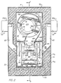
- the oven 70 comprises spaced side walls 72 and 74, a back wall 76 and a front wall 78.
- Front wall 78 has an access opening 79 formed therein which is opened or closed by a door 80.
- a microwave trap 81 is formed around door 80 and is configured to prevent passage of microwave energy through space between the periphery of the door 80 and walls of the oven 70.
- Top wall 71 and bottom wall 73 close upper and lower ends of oven 70.
- Each wall of the oven is preferably formed by spaced metallic sheets and the space between the sheets is filled with thermal insulation material.
- Actuator 82 secured to mounting bracket 82a, is connected through a link 84 to door 80 for moving door 80 vertically relative to access opening 79.
- Actuator 82 is preferably an electromechanical actuator of the type illustrated in FIG. 14 and is driven by a motor 51a.
- electromagnetic radiation device 90 in the illustrated embodiment comprise a pair of magnetrons 92 connected to wave guides 93 formed in side walls 72 and 74 of oven 70.
- the magnetrons 92 supply electromagnetic energy to wave guides which carry the energy to the cooking chamber.
- a preferred microwave frequency is 2450 megahertz.
- Magnetrons 92 are conventional vacuum tubes in the microwave oven that convert electrical energy to electro magnetic energy in the microwave frequency spectrum. Waves of microwave energy are similar to radio waves except they are higher frequency than radio waves lower frequency than ordinary light waves.
- the microwave energy is channeled through wave guides 93 from the magnetrons 92 into the cooking chamber 120.
- the side walls 72 and 74 are formed by spaced sheets 74a and 74b and insulation material 74c is configured to form a guide tube 93 having a lower end 94 which is inclined at an angle 95 relative to a vertical plane 96 at an angle in a range between 15° and 75°.
- the angle 95 is approximately 45°.
- microwave radiant heating is delivered from two sides and angles downwardly toward food 30 in an open top container 18. Since the container and the food in the container do not reflect microwave significantly and since the space under the container diffuses microwave which passes through or by the container the beam from one wave guide is not reflected directly into the other but is largely retained in the heating chamber.
- the container 18 is non-metallic reflections from one wave guide 93 are not reflected into the other to keep microwave in the chamber 120 to effectively heat the food 30.
- the container preferably is formed of material which is less than 25% reflective of microwave energy, such material being heated by the microwave to heat the surface of the food product where it contacts the surface of the container.
- the support for the open package is preferably less than 25% reflective of the microwave.
- the reflective surface of the bottom 24 of the container 18 is greater than one-fourth wave length, for 2450 megahertz (MHZ) microwave one-fourth of 13 cm, below the surface of food being heating.
- MHZ megahertz
- a tube 103 is connected through a valve 103a to a supply of water or steam and which may be used for delivering an atomized spray of water or steam into the air conditioning chamber 115 for controlling the relative humidity and dew point of air circulated through air conditioning chamber 115 and cooking chamber 120.
- air circulating apparatus generally designated by the numeral 100 comprises a blower housing 102 having an inlet opening 104 and a discharge opening 106.
- blower housing 102 is in the form of a volute and a plenum section 108 is formed adjacent the discharge opening 106.
- a radial flow fan impeller 110 draws air axially through inlet opening 104 and discharges air radially through plenum section 108 and discharge opening 106.
- a heating element 112 having coils 113 of a first stage and coils 114 of a second stage is mounted for heating air drawn into the blower housing 102.
- Perforated plate 75 is constructed of a metallic material and has perforations 76 with relatively small openings equivalent to more than 50% of the surface area.
- the perforated metal sheet 75 prevents microwave energy from passing into the air conditioning chamber 115.
- the first stage of coils 113 is mounted in air conditioning chamber 115 outside of the blower housing 102 while the second stage 114 of coils is mounted inside blower housing 102.
- Terminals 112a and 112b of heating element 112 are connectable to a suitable source of electricity.
- a mounting plate 116 having a notch 117 formed in the periphery thereof and a central opening 118 is bolted or otherwise secured to blower housing 102 for supporting heating element 112.
- Plate 116 is formed in two parts which are connectable along a part line 119.
- blower 110 is mounted on a shaft which is driven through a coupling 111 by a motor 110a.
- Coils 109 of a third stage heating element 109 is mounted in the plenum section 108 of blower housing 102 and positioned such that air delivered radially from blower 110 is heated immediately prior to being delivered through discharge opening 106. It should be readily apparent that only coils 109 may be activated while coils 113 and 114 are idle, if it is deemed expedient to do so depending upon the heating requirements of a particular food product.
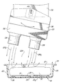
- An air dispensing duct generally designated by the numeral 125 is secured to plenum 108 for receiving air from discharge opening 106.
- air dispensing apparatus 125 comprises a tapered duct formed by a perforated plate 126 having an array of passages formed therein which communicate with tubes 128.
- a front wall 130 and a rear wall 132 extend upwardly from the perforated plate 126 and are connected between side walls 134 and 136.
- An inclined top wall 138 extends between front wall 130 and a flange 140 encircling the lower end of plenum 108 and enclosing the discharge opening 106 from the blower housing 102.
- air directing vanes 143 extend between side walls 134 and 136 of the tapered duct for distributing air along the length of the interior of the tapered duct.
- the air dispensing apparatus 125 is pivotally secured to duct 108 by a pivot pin 142 extending through aligned apertures 144 in flange 140. Pivot pin 142 extends into an opening 145 formed in lug 146 on shaft 148 which extends into an aperture 149 on a link 150. Link 150 has an elongated slot 152 formed therein into which a pin 154 on crank 155 extends.
- Crank arm 155 has an aperture which receives a drive shaft 158 driven by motor 160 through a gear reducer 161.
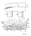
- a radial blower 110 discharging its highest velocity air from the outer portion of the volute downwardly through shaped openings in tubes 128 to impinge upon a narrow food product 30 in the open top container 18.
- the air dispensing duct 125 is moved relative to the product 30 to give uniform coverage by the air streams.
- the sides 22 and 23 of the container 18 cause a portion of the air stream to be deflected to heat the sides and bottom 31 of product 30 in the container.
- the movement applies the air streams near one side of the container adjacent side wall 22 and then to the other side adjacent side wall 23 so that parts of the air streams are alternately applied to opposite exposed sides of the product 30 and are caused to alternate the lateral flow through loose stacks of food products 30 such as curled or random lengths of french fried potatoes.
- This alternating lateral air flow through paths 28 between support ribs 25 passes under and heats the lower side 31 of irregularly shaped products such as bone-in chicken parts.
- the moving air dispensing apparatus 125 provides moving reflective surfaces which serve as stirrers to help distribute the microwave energy in the cooking chamber 120.
- the spent air travels through space 129 between tubes 128, as illustrated in FIGS. 11 and 12 of the drawing.
- Spent air travels upwardly adjacent baffles 162 and is then directed downwardly by a curved surface 164 along a path between baffle 162 and baffle 166 downwardly toward soil collector pans 165.
- Soil collector pans 165 are preferably removably mounted and are maintained at a temperature which is less than the temperature of any other surface in the oven 70 for causing very fine smoke-type particles in the moving air to be collected on the coldest surface in the recirculating path. From soil pans 165 the recirculating air is directed upwardly between the outer surface of baffle 166 and sheet 74b of side wall 74 upwardly through passages formed in the perforated plate 75.
- Baffles 162 and 166 are preferably constructed of material which is relatively transparent to microwave energy. To assure that the soil collection pans 165 are maintained cooler than other surfaces in oven 70, the pans may be exposed to outside air or water cooling to facilitate collecting aerosol from the recirculating air.
- the disclosed method for controlling the temperature and surface texture of a food product which is to be delivered from vending machine 200 generally comprises delivery of a suitably packaged and preserved food product from a storage compartment 170 to an oven 70.
- the package 10 is positioned by back stop member 45 in a predetermined relationship relative to electromechanical linear actuators 50 and 60 and relative to access opening 79 communicating with cooking chamber 120 in oven 70.
- Actuation of the actuator of the loading device 50 results in movement of push plate 57a through tubular sleeve 12 for pushing container 18 out of sleeve 12 and into the cooking chamber 120.
- Streams 28a of air delivered through tubes 128 of the air circulating apparatus 100 melts and shrinks film 27a for uncovering food product 30 in the open top container 18.
- one or more air streams 128a after causing the food product 30a in container 18 to be uncovered will be delivered through the open top of container 18b. If the food product 30a in the container is strips or slices of pasta, potatoes or other particulate material, air from stream 128a will be delivered through the stacked material in heat transfer relation with the surface of the pieces of the food product.
- air dispensing duct 125 is preferably rocked causing air streams 128a and 128b to move across the surface of the food product between lateral edges thereof such that regions of controlled air pressure are alternately formed adjacent opposite sides of the product 30 such that temperature controlled air flows through passage 28 between the lower surface 31 of the food product and the upper surface 25a of the bottom 24 of container 18.
- the recirculating air tends to limit localized heating of the product by microwave energy delivered by magnetrons 92. Tips, and thin areas of the product which are rapidly heated by the microwave energy may actually dissipate heat to air in streams 128a and 128b to provide cooling to certain portions of the food product.
- air flow through the air circulating apparatus 100 is terminated, magnetrons 92 are turned off and blower actuator 82 is energized for moving the door upwardly to the position illustrated in FIG. 1 of the drawing.
- the electromechanical actuator of the container unloading device 60 is then actuated for moving rake plate 57b from the dashed outline position in FIG. 5 of the drawing to the full outline position. Rake plate 57b is then lowered and retracted for moving container 18 out of the oven and redepositing the hot container and the food therein in the tubular sleeve 12.
- conveyor 65 is energized for moving the heated food product toward the delivery passage 124 of the vending machine 200 such that the product is accessible to the customer by opening protective door 225.
Abstract
Description
- The disclosed invention relates to a hot meal vending device which employs a combination of microwave and convection heating.
- Vending machines for dispensing hot and cold drinks, candy, cookies, potato chips and other snack foods have enjoyed significant commercial success. However, vending machines for dispensing meals have been limited to dispensers of refrigerated foods such as sandwiches, salads and the like.
- Devices heretofore devised for incorporating electronic ovens in food vending machines are disclosed in U.S. Patent No. 3,333,666; U.S. Patent No. 3,343,479; U.S. Patent No. 3,386,550; U.S. Patent No. 3,397,817; U.S. Patent No. 3,534,676; U.S. Patent No. 4,004,712; U.S. Patent No. 4,398,651; U.S. Patent No. 4,592,485; U.S. Patent No. 4,762,250; U.S. Patent No. 4,783,582 and U.S. Patent No. 4,784,292.
- Vending machines for hot meals generally include a refrigerated compartment for preserving food, a microwave oven compartment for fast cooking, and a conveyor for transferring food from the refrigerated compartment into the microwave oven. However, since vending machines for hot foods have enjoyed very limited commercial success, separate microwave ovens for heating food items removed from a refrigerator are commonly employed in convenience stores, airports, cafeterias and other food vending operations.
- Microwave heating of certain foods, including pizza and sandwiches which contain dough and bakery products, typically leaves the surface too moist and less palatable than similar food products cooked in other types of ovens.
- Ovens of the type disclosed in U.S. Patent No. 3,884,213; U.S. Patent No. 4,154,861; U.S. Patent No. 4,289,792; U.S. Patent No. 4,409,453 and U.S. Patent No. 4,835,351 employ air jets which impinge upon the surface of a food product to provide surface heating of the product in combination with microwave heating. US-4409453 also discloses means for dividing the interior of an oven cabinet into a cooking chamber and an air heating chamber as required by the pre-characterising part of claim 1 hereinafter.
- Jet impingement ovens have enjoyed significant success in commercial food service and commercial food processing operations. However, a long felt need exists for apparatus for quickly and efficiently heating food products which require little or no preparation for use in a vending machine for hot meals.
- According to the present invention there is provided a microwave oven for controlling the temperature and surface texture of a food product comprising: a cabinet; perforated dividing means in said cabinet dividing the interior of the cabinet into a cooking chamber and an air conditioning chamber; air circulating means comprising an impeller in said conditioning chamber to draw air through said perforated dividing means and dispense air from said air conditioning chamber into said cooking chamber; heater means in said air conditioning chamber and microwave heating means communicating with said cooking chamber, said perforated dividing means preventing transfer of microwave energy from said cooking chamber to said air conditioning chamber; characterised in that the heater means is positioned in the air flow between said perforated dividing means and said impeller.
- Drawings of apreferred embodiment of microwave vending machine are annexed hereto so that the invention may be better and more fully understood, in which:
- FIG. 1 is a perspective view of a package handling apparatus and oven cabinet inside a vending machine, the outer cabinet of the vending machine being broken away to more clearly illustrate details of construction;
- FIG. 2 is a cross-sectional view taken along line 2-2 of FIG. 1;
- FIG. 3 is a cross-sectional view taken along line 3-3 of FIG. 2;
- FIG. 4 is an exploded perspective view of the air dispensing apparatus;
- FIG. 5 is a cross-sectional view taken along line 5-5 of FIG. 1;
- FIG. 6 is a cross-sectional view taken along line 6-6 of FIG. 1;
- FIG. 7 is an exploded perspective view of a container and protective sleeve which form a package for a food product;
- FIG. 8 is an elevational view of the package illustrated in FIG. 7, parts being broken away to more clearly illustrated details of construction;
- FIG. 9 is a fragmentary diagrammatic view illustrating a modified form of a food container having susceptor film mounted therein;
- FIG. 10 is a fragmentary diagrammatic view of a food container having a bottom layer of french fried food material and an upper layer of a different food product;
- FIG. 11 is a diagrammatic view illustrating air flow during a first stage of the cooking process; and
- FIG. 12 is a diagrammatic view similar to FIG. 11 illustrating air flow during a second stage of the cooking process;
- FIG. 13 is a perspective view of the external vending machine cabinet;
- FIG. 14 is a cross sectional view taken through the electromechanical linear actuator;
- FIG. 15 is a diagrammatic view similar to FIG. 11 illustrating air flow through a particulate food product;
- FIG. 16 is a perspective view of a container having a lattice bridging the open top thereof;
- FIG. 17 is a perspective view of the bottom of the container illustrated in FIG. 16;
- FIG. 18 is a cross-sectional view taken along line 18-18 of FIG. 16; and
- FIGS. 19-21 are cross-sectional views similar to FIG. 18 diagrammatically illustrating the progressive heating of a film sealing the container to uncover a food product in the container.
-
- Numeral references are employed to designate like parts throughout the various figures of the drawing.
- Referring to FIGS. 1, 4, 7 and 13 of the drawings, the
numeral 10 generally designates a package which is moved bypackage handling apparatus 40 into and out of anoven 70 in avending machine 200. As will be hereinafter more fully explained, asource 90 of electromagnetic radiation andair circulating apparatus 100 are employed for heating afood product 30 selected by a consumer upon depositing the purchase price of the food product in thevending machine 200 illustrated in FIG. 13. As best illustrated in FIG. 13 of the drawing, thevending machine 200 is preferably adapted to serve, for example,hot food products 30 to a customer within about one and a half to two minutes. In the illustrated embodiments, thefood products 30 may, for example, include french fried potatoes, chicken nuggets, pizza, and submarine sandwiches. - The
vending machine 200 is mounted in an enclosure cabinet having aback wall 201, spacedside walls front panel 205, atop wall 206 and abottom wall 208. Thefront panel 205 is preferably hingedly secured toside wall 202 and provided with a key actuatedlock 210 securing thefront panel 205 in a closed and locked position to prevent unauthorized access to the interior of the enclosure. Acurrency receiving mechanism 212 adapted to accept both coins and bills is mounted onfront panel 205 along with acoin return slot 214 for returning change to the customer. -
Selector plates front panel 205 for use by the customer to designate the food item selected to be heated and dispensed through adelivery passage 224 closed by aprotective door 225.Product identification panels selector plates Identification panel 215 is provided with a graphic illustration of fried potatoes permitting use of thevending machine 200 by persons who do not speak or read a particular language. Additional indicia including words, numerals or other and graphic representations may be applied to each of thepanels - A
condiment holding chamber 209 is provided for holding packets of salt, pepper, sugar, ketchup, mustard and barbecue sauce. - As will be hereinafter more fully explained, a refrigerated
food storage cabinet 170 is preferably mounted in the lower portion of the interior of theenclosure 200 andpackage handling apparatus 40 andoven 70 are mounted above and adapted to receive selected packages of food products from the refrigeratedstorage compartment 170 transported by anelevator 180. - Each
selector plate food item 30 has been received in thecurrency receiving mechanism 212. As will be hereinafter more fully explained, touchingselector plate 220 indicates that pizza, graphically illustrated onproduct identification panel 219 is to be dispensed. Acontainer 10 containing pizza will be automatically moved from the refrigeratedstorage compartment 170 onto anelevator 180 and delivered to thepackage handling apparatus 40 which will move thepackage 10 tooven 70 for heating and then dispense the heatedproduct 30 through thedelivery passage 224 which is accessible to the customer by raisingdoor 225. - The electrical circuit controlling the heating of the selected
food product 30 preferably includes three programmed elements for delivering a predetermined type of heating for a pre-programmed time interval to the selected food product. The programmable circuit preferably includes, for example, devices to program the heating cycle by coordination with the location of the selected food item in thestorage compartment 170, a bar code or other readable mechanism on the package, and symbols displayed on or adjacent selector plates 215-221 for the user to touch. From the foregoing, it should be readily apparent that touching one of theselector plates product identification panels food product 30. -
Package 10, best illustrated in FIGS. 7 and 8, comprises atubular sleeve 12 havingopen ends 13a and 13b.Sleeve 12 is formed by a top 14, bottom 15 andside walls 16a and 16b having peripheral edges connected to form aninterior cavity 17 for acontainer 18.Bottom 15 is narrower than top 14 andsidewalls 16a and 16b are inclined relative to vertical planes. -
Container 18 is an open topped tray formed byside walls end walls bottom wall 24.Support ribs 25 or other suitable projections extend upwardly frombottom wall 24 for supporting afood product 30 spaced frombottom wall 24 to provide space forming apath 28 extending between thelower surface 31 of thefood product 30 and the upper surface 25a of thebottom wall 24 ofcontainer 18. - The
package 10 carries thefood product 30 in the open-top container 18 which is enclosed in the tube-like sleeve 12, preferably constructed of cellulosic or other poorly conductive material. Thefood product 30 is stored in acabinet 170 in thecontainer 18 inside of the sleeve covers 12. Thecontainer 18 is withdrawn from thesleeve 12 prior to heating thefood product 30 and then thefood 30 andcontainer 18 are returned to thesleeve 12 to retain heat in the food until thepackage 10 is opened by the customer. - It should be readily apparent that refrigeration of
food product 30 may not be necessary iffood product 30 is not perishable or ifpackage 10 containing the food product has been treated to assure thatfood product 30 has sufficient shelf life.Cabinet 170 may be refrigerated or divided into compartments, some of which are refrigerated depending upon the nature of the food product to be dispensed by thevending machine 200. - The relatively
non-conducting sleeve 12 serves as a comfortable holder for thehot container 18 andfood 30. - The cover for the
container 18, having alip 19 which extends around the periphery of upper edges ofwalls sleeve 12 to provide a slip-over lid which covers the open top of thecontainer 18 and can be removed for heating and subsequently provides insulated cool handling of thehot product 30 by enclosing thelip 19 of thecontainer 18. - In FIG. 9 of the drawing, the numeral 18a generally designates a modified form of the container having a
susceptor belt 27 mountedadjacent bottom 24 of thecontainer having ribs 25 formed thereon. Thesusceptor belt coating 27 is formed of polyethylene terephthalate and is commercially available from a variety of sources including Frigigold of England and is recommended for use in reusable plastic or paperboard microwave cook ware in a recommended temperature range of up to 232°C (450°F). Thesusceptor belt 27 is rapidly heated by microwave energy until it reaches a maximum temperature of, for example, 177°C (350°F) and the temperature level is maintained to provide radiant and conductive bottom heat to thefood product 30. - In the embodiment of the
container 18 illustrated in FIG. 10 of the drawing, alayer 29 of a particulate food product, such as strips of pasta or slices of potato, is positioned between thebottom wall 24 ofcontainer 18 and thelower surface 31 offood product 30. Iflayer 29 is slices of potato andproduct 30 is a meat product, juices dripping from the lower surface offood product 30 will contact and be absorbed bylayer 29 of potato slices to enhance the cooking of both the slices of potato and themeat product 30. The liquid juices enhance the flavor and appearance of the potatoes while the circulation of air throughpassages 28 between the potato slices results in controlled drying and evaporation of moisture from the bottom of thefood product 30 to provide an acceptable texture, taste, smell and appearance superior to that conventionally achieved in microwave ovens. - As illustrated in FIGS. 15-21 of the drawing, the food product 30a may comprise particulate material, such as slices of fried potatoes and a
corrugated susceptor belt 27 is mounted adjacent bottom 24 to formribs 25. Since thesusceptor belt 27 is controllably heated by the microwave and portions of the upwardly extendingribs 25 contact the lower surface of the food product, the structure simulates grilling as well as allowing juices to flow into the area between the ribs. -
Container 18b, illustrated in FIG. 15, is provided with a sheet 27a of a heat shrinkable film bonded to lip 19a for sealing the food product 30a in the container 30b. A sheet 27a preferably formed of polymeric compounds and materials, for example, synthetic thermoplastic resins of the type which are commercially available from E.I. DuPont de Nemours and Co. of Wilmington, Delaware, used to form a polyester film which will melt when contacted by air at a temperature of less than 204°C (400°F) which results in film 27a becoming perforated and rolling towardlip 19 which extends around the periphery ofcontainer 18b. The cohesive nature of the polyester material prevents it from dripping into the food container. It should be readily apparent that the use of the polyester film 27a provides a seal which prevents deterioration of food product 30a over an extended period of time in a refrigerator or freezer. - A perforated grid or
lattice 27b, illustrated in FIG. 16 and FIGS. 18-21, may be mounted between the upper surface oflip 19 and the lower surface of sheet 27a.Legs 27c and 27d spanning across the top ofcontainer 18b support film 27a to assure that portions of film 27a do not drop downwardly to engage the food product 30a incontainer 18b. - As diagrammatically illustrated in FIGS. 18-21 of the drawing, film 27a and
lattice 27b are bonded or otherwise sealingly secured to thelip 19 which extends around the periphery of the open top ofcontainer 18b to prevent dehydration and to otherwise protectfood product 30 incontainer 18b.Food product 30 is supported onsusceptor belt 27 having upwardly extendingprojections 25 formed thereon for spacing the lower surface offood product 30 above the bottom ofcontainer 18b to form air passages therebetween as hereinbefore described. - As illustrated in FIG. 19 of the drawing, impingement of air stream 28a against the upper surface of film 27a causes a central portion of film 27a to be perforated forming an opening 27a' in a central portion of the film intermediate edges of
container 18b. - As illustrated in FIG. 20, opening 27a' is enlarged as heat is transferred to the film 27a which tends to roll back as indicated at 27a" as the film material shrinks and is distorted.
- As illustrated in FIG. 21 of the drawing, heat transferred to the film 27a causes the meltable and shrinkable film 27a to retract to the position designated 27a''' thereby uncovering the upper surface of
food product 30 incontainer 18b. - It should be appreciated that
container 18b is preferably stored in atubular sleeve 12 of the type hereinbefore described to prevent perforation of sealing film 27a during handling of containers while being transported for stockingstorage cabinet 170. As will be hereinafter more fully explained, aftercontainer 18b has been moved into heat exchange relation with streams 128a of heated air projected byair circulating apparatus 100,container 18b is reinserted into thetubular sleeve 12 prior to dispensing the food product to the customer so that thehot container 18b and thefood product 30 therein can be handled by the customer to eliminate the necessity for providing "hot pads" or other apparatus for handling the hot container. - As best illustrated in FIGS. 1 and 14,
package handling apparatus 40 includes acontainer loading device 50 and acontainer unloading device 60. Theloading device 50 and unloadingdevice 60 are of substantially identical construction andcomprise motors 51a and 51b, respectively, drivingly connected throughsynchronous drive belts 52 to the end of drive screws 56. Eachdrive screw 56 has threads formed on the outer surface thereof which engage internal threads in a drive nut 55 which moves linearly alongdrive screw 56 as the drive screw rotates. Thrust is transmitted from the drive nut 55 to atransitional tube 57. Theentire screw 56 and nut 55 assembly is protected from contamination and environmental elements by acover tube 58, and anend wiper seal 59.Rotational thrust bearings 54 allow thescrew 56 to freely rotate under loaded conditions. - The electromechanical
linear actuators -
Motors 51a and 51b are preferably variable speed reversible synchronous gear motors. It should be readily apparent thatmotors 51a and 51b transmit torque throughbelt 52 for rotating drive screws 56. Rotation ofdrive screw 56 causes drive nut 55 which is secured to the inner end of translatingtube 57 to move translatingtube 57 to extend or retracttube 57 relative to covertube 58. - As diagrammatically illustrated in FIG. 5 of the drawing,
electromechanical actuator 60 havingrake plate 57b mounted thereon is pivotally mounted between a pair of lugs 60a and is rocked in a vertical plane by a solenoid 60b connected to anactuating arm 60c secured to covertube 58 ofactuator 60. - When
rake plate 57b is in its retracted home position indicated in dashed outline at 57b in FIG. 5 of the drawing,rake plate 57b is preferably positioned at an elevation abovecontainer 18 such that when translatingtube 57 is extended to the full outline position, the lower edge ofrake plate 57b moves above the upper edge ofcontainer 18. Whenrake plate 57b reaches the full outline position illustrated in FIG. 5 of the drawing, solenoid 60b is actuated for movingrake plate 57b downwardly to an elevation below the lip extending aroundcontainer 18 such that when translatingtube 57 is retracted to the dashed outline position,container 18 will be returned throughpassage 48 inproduct guide member 46 and returned to the interior oftubular sleeve 12. Aftercontainer 18 has been deposited intubular sleeve 12, solenoid 60b will again be actuated for elevatingrake plate 57b to a position above the upper edge of opening 48 such that pusher plate 57a may be actuated for moving thenext container 18 into the oven. -
Conveyor 65 includes aflexible belt 66 extending around a drive roller 66a and a driven roller 66b, drive roller 66a being driven by a reversiblevariable speed motor 68. - The in-feed conveyor, generally designated by the numeral 42, comprises a
paddle 43 suspended between chains 43a and 43b which extend around drive sprockets mounted on a shaft driven by amotor 43d. Theinfeed conveyor 42 is mounted betweenguide members guide member 44 comprises a generally L-shaped member formed by substantially perpendicularly disposedlegs 44a and 44b connected by a transition section 44c.Product guide member 44 is connected to a secondproduct guide member 46 by a front bracket 42f and a rear bracket 42r. As illustrated in FIG. 1 of the drawing, an in-feed drive motor 43d is secured to guidemember 46 andpaddle 43 is moved betweenguide members -
Product guide member 46, best illustrated in FIG. 5, is formed by generally perpendicularly disposedlegs 46a and 46b connected by a transition section 46c. Athird leg 46d extends generally parallel toleg 46b and has an end secured to an end ofleg 46b bystop member 45. As will be hereinafter more fully explained,stop member 45 functions as a stop to limit movement ofpackage 10. -
Leg 46b ofproduct guide member 46 has afirst passage 47 formed therein whilesection 44d has asecond passage 48 formed therein. As will be hereinafter more fully explained, whenconveyor 65moves package 10 into engagement withbackstop 45, the open end 13a oftubular sleeve 12 is positionedadjacent opening 47 while theopen end 13b ofsleeve 20 is positionedadjacent passage 48. Whenmotor 51a of the linear actuator ofloader assembly 50 is energized,tube 57 and push plate 57a on the end thereof will move throughpassage 47 and through theopen end 13b ofsleeve 12 for movingcontainer 18 through the open end 13a ofsleeve 12 and throughpassage 48 into a cooking chamber inoven 70. Aftercontainer 18 is positioned in the cooking chamber,motor 51a is reversed, thereby retracting translatingtube 57 and push plate 57a to the position illustrated in FIG. 1 of the drawing. - After the
product 30 incontainer 18 has been heated, motor 51b of the linear actuator of the unloadingassembly 60 will be energized to extend the translatingtube 57 of the unloadingassembly 60 causing therake plate 57b to move into the cooking compartment abovecontainer 18 and then pivot downwardly for engaginglip 19 onend wall 21 oncontainer 18. Motor 51b is then reversed for retractingtube 57 andrake plate 57b for urgingcontainer 18 out of theoven 70, throughpassage 48 and through the open end 13a ofsleeve 12. Whenmotor 68 is energized, theheated food product 30 incontainer 18 which has been repositioned insleeve 12 will be moved toward the delivery end ofconveyor 65. -
Product guide members feed conveyor 42 anddelivery conveyor 65 are mounted. - The
oven 70 comprises spacedside walls back wall 76 and afront wall 78.Front wall 78 has an access opening 79 formed therein which is opened or closed by adoor 80. Amicrowave trap 81 is formed arounddoor 80 and is configured to prevent passage of microwave energy through space between the periphery of thedoor 80 and walls of theoven 70.Top wall 71 andbottom wall 73 close upper and lower ends ofoven 70. Each wall of the oven is preferably formed by spaced metallic sheets and the space between the sheets is filled with thermal insulation material. - An
actuator 82, secured to mounting bracket 82a, is connected through alink 84 to door 80 for movingdoor 80 vertically relative to accessopening 79.Actuator 82 is preferably an electromechanical actuator of the type illustrated in FIG. 14 and is driven by amotor 51a. - Referring to FIGS. 1 and 2 of the drawing, electromagnetic radiation device generally designated by the numeral 90 in the illustrated embodiment comprise a pair of
magnetrons 92 connected to waveguides 93 formed inside walls oven 70. Themagnetrons 92 supply electromagnetic energy to wave guides which carry the energy to the cooking chamber. A preferred microwave frequency is 2450 megahertz.Magnetrons 92 are conventional vacuum tubes in the microwave oven that convert electrical energy to electro magnetic energy in the microwave frequency spectrum. Waves of microwave energy are similar to radio waves except they are higher frequency than radio waves lower frequency than ordinary light waves. The microwave energy is channeled through wave guides 93 from themagnetrons 92 into thecooking chamber 120. - As illustrated in FIG. 2 of the drawing, the
side walls sheets 74a and 74b and insulation material 74c is configured to form aguide tube 93 having alower end 94 which is inclined at anangle 95 relative to avertical plane 96 at an angle in a range between 15° and 75°. In the illustrated embodiment, theangle 95 is approximately 45°. - The application of microwave radiant heating is delivered from two sides and angles downwardly toward
food 30 in an opentop container 18. Since the container and the food in the container do not reflect microwave significantly and since the space under the container diffuses microwave which passes through or by the container the beam from one wave guide is not reflected directly into the other but is largely retained in the heating chamber. - Since the
container 18 is non-metallic reflections from onewave guide 93 are not reflected into the other to keep microwave in thechamber 120 to effectively heat thefood 30. The container preferably is formed of material which is less than 25% reflective of microwave energy, such material being heated by the microwave to heat the surface of the food product where it contacts the surface of the container. - The support for the open package is preferably less than 25% reflective of the microwave.
- The reflective surface of the bottom 24 of the
container 18 is greater than one-fourth wave length, for 2450 megahertz (MHZ) microwave one-fourth of 13 cm, below the surface of food being heating. The angle and the distance reduce standing waves in the small heating cavity. - A
tube 103 is connected through a valve 103a to a supply of water or steam and which may be used for delivering an atomized spray of water or steam into theair conditioning chamber 115 for controlling the relative humidity and dew point of air circulated throughair conditioning chamber 115 andcooking chamber 120. - Referring to FIGS. 2, 3 and 4 of the drawing, air circulating apparatus generally designated by the numeral 100 comprises a
blower housing 102 having aninlet opening 104 and adischarge opening 106. As illustrated in FIGS. 2 and 4,blower housing 102 is in the form of a volute and aplenum section 108 is formed adjacent thedischarge opening 106. - A radial
flow fan impeller 110 draws air axially through inlet opening 104 and discharges air radially throughplenum section 108 anddischarge opening 106. - A
heating element 112 havingcoils 113 of a first stage and coils 114 of a second stage is mounted for heating air drawn into theblower housing 102. - As best illustrated in FIG. 3 of the drawing, the interior of the
cabinet 70 is divided by aperforated plate 75 to form anair conditioning chamber 115 and acooking chamber 120. Perforatedplate 75 is constructed of a metallic material and hasperforations 76 with relatively small openings equivalent to more than 50% of the surface area. Theperforated metal sheet 75 prevents microwave energy from passing into theair conditioning chamber 115. - As best illustrated in FIG. 3 of the drawing, the first stage of
coils 113 is mounted inair conditioning chamber 115 outside of theblower housing 102 while thesecond stage 114 of coils is mounted insideblower housing 102.Terminals 112a and 112b ofheating element 112 are connectable to a suitable source of electricity. - As illustrated in FIG. 4 of the drawing, a mounting
plate 116 having anotch 117 formed in the periphery thereof and acentral opening 118 is bolted or otherwise secured toblower housing 102 for supportingheating element 112.Plate 116 is formed in two parts which are connectable along apart line 119. - As illustrated in FIG. 3,
blower 110 is mounted on a shaft which is driven through a coupling 111 by a motor 110a. - Coils 109 of a third stage heating element 109 is mounted in the
plenum section 108 ofblower housing 102 and positioned such that air delivered radially fromblower 110 is heated immediately prior to being delivered throughdischarge opening 106. It should be readily apparent that only coils 109 may be activated whilecoils - An air dispensing duct generally designated by the numeral 125 is secured to plenum 108 for receiving air from
discharge opening 106. - As best illustrated in FIGS. 3 and 4 of the drawing,
air dispensing apparatus 125 comprises a tapered duct formed by aperforated plate 126 having an array of passages formed therein which communicate withtubes 128. Afront wall 130 and arear wall 132 extend upwardly from theperforated plate 126 and are connected betweenside walls top wall 138 extends betweenfront wall 130 and aflange 140 encircling the lower end ofplenum 108 and enclosing the discharge opening 106 from theblower housing 102. - As illustrated in FIG. 3 of the drawing,
air directing vanes 143 extend betweenside walls - The
air dispensing apparatus 125 is pivotally secured toduct 108 by apivot pin 142 extending through alignedapertures 144 inflange 140.Pivot pin 142 extends into anopening 145 formed in lug 146 onshaft 148 which extends into anaperture 149 on a link 150. Link 150 has an elongated slot 152 formed therein into which a pin 154 on crank 155 extends. - Crank
arm 155 has an aperture which receives adrive shaft 158 driven bymotor 160 through agear reducer 161. - A
radial blower 110 discharging its highest velocity air from the outer portion of the volute downwardly through shaped openings intubes 128 to impinge upon anarrow food product 30 in the opentop container 18. - The
air dispensing duct 125 is moved relative to theproduct 30 to give uniform coverage by the air streams. As best illustrated in FIGS. 11 and 12, thesides container 18 cause a portion of the air stream to be deflected to heat the sides and bottom 31 ofproduct 30 in the container. The movement applies the air streams near one side of the containeradjacent side wall 22 and then to the other sideadjacent side wall 23 so that parts of the air streams are alternately applied to opposite exposed sides of theproduct 30 and are caused to alternate the lateral flow through loose stacks offood products 30 such as curled or random lengths of french fried potatoes. This alternating lateral air flow throughpaths 28 betweensupport ribs 25 passes under and heats thelower side 31 of irregularly shaped products such as bone-in chicken parts. - The effectiveness of the sideways air heating of
lower surfaces 31 can be enhanced byribs 25 to provide air passages under flat products. - Further, the moving
air dispensing apparatus 125 provides moving reflective surfaces which serve as stirrers to help distribute the microwave energy in thecooking chamber 120. - The combination of extended orifices through
tubes 128, and the opentop container 18 providesair escape path 129 while bringing the orifice to an optimum distance from theproduct 30. It should be noted that upper edges of thesides container 18 extend above the height of the containedproduct 30 to enhance air flow between thelower surface 31 of theproduct 30 and the bottom 24 ofcontainer 18. - As illustrated in FIG. 2 of the drawing, streams of air dispensed from
air dispensing duct 125 through hollowair dispensing tubes 128 impinge upon the upper surface of afood product 30 incontainer 18. The spent air travels throughspace 129 betweentubes 128, as illustrated in FIGS. 11 and 12 of the drawing. Spent air travels upwardlyadjacent baffles 162 and is then directed downwardly by acurved surface 164 along a path betweenbaffle 162 and baffle 166 downwardly toward soil collector pans 165. Soil collector pans 165 are preferably removably mounted and are maintained at a temperature which is less than the temperature of any other surface in theoven 70 for causing very fine smoke-type particles in the moving air to be collected on the coldest surface in the recirculating path. From soil pans 165 the recirculating air is directed upwardly between the outer surface ofbaffle 166 andsheet 74b ofside wall 74 upwardly through passages formed in theperforated plate 75. -
Baffles oven 70, the pans may be exposed to outside air or water cooling to facilitate collecting aerosol from the recirculating air. - From the foregoing it should be readily apparent that the disclosed method for controlling the temperature and surface texture of a food product which is to be delivered from
vending machine 200 generally comprises delivery of a suitably packaged and preserved food product from astorage compartment 170 to anoven 70. Thepackage 10 is positioned byback stop member 45 in a predetermined relationship relative to electromechanicallinear actuators opening 79 communicating withcooking chamber 120 inoven 70. - Actuation of the actuator of the
loading device 50 results in movement of push plate 57a throughtubular sleeve 12 for pushingcontainer 18 out ofsleeve 12 and into thecooking chamber 120. Streams 28a of air delivered throughtubes 128 of theair circulating apparatus 100 melts and shrinks film 27a for uncoveringfood product 30 in the opentop container 18. - In the embodiment illustrated in FIG. 15 of the drawing, one or more air streams 128a, after causing the food product 30a in
container 18 to be uncovered will be delivered through the open top ofcontainer 18b. If the food product 30a in the container is strips or slices of pasta, potatoes or other particulate material, air from stream 128a will be delivered through the stacked material in heat transfer relation with the surface of the pieces of the food product. - If
food product 30 is a solid article as designated by the numeral 30 in FIGS. 11 and 12 of the drawing,air dispensing duct 125 is preferably rocked causing air streams 128a and 128b to move across the surface of the food product between lateral edges thereof such that regions of controlled air pressure are alternately formed adjacent opposite sides of theproduct 30 such that temperature controlled air flows throughpassage 28 between thelower surface 31 of the food product and the upper surface 25a of the bottom 24 ofcontainer 18. - After the surface of the
food product 30 has been heated byair streams 128a and 128b, the recirculating air tends to limit localized heating of the product by microwave energy delivered bymagnetrons 92. Tips, and thin areas of the product which are rapidly heated by the microwave energy may actually dissipate heat to air instreams 128a and 128b to provide cooling to certain portions of the food product. - After the
food product 30 incontainer 18 has been sufficiently heated, air flow through theair circulating apparatus 100 is terminated,magnetrons 92 are turned off andblower actuator 82 is energized for moving the door upwardly to the position illustrated in FIG. 1 of the drawing. The electromechanical actuator of thecontainer unloading device 60 is then actuated for movingrake plate 57b from the dashed outline position in FIG. 5 of the drawing to the full outline position.Rake plate 57b is then lowered and retracted for movingcontainer 18 out of the oven and redepositing the hot container and the food therein in thetubular sleeve 12. - After the heated food product and
container 18 have been moved into the protectivetubular sleeve 12,conveyor 65 is energized for moving the heated food product toward thedelivery passage 124 of thevending machine 200 such that the product is accessible to the customer by openingprotective door 225.
Claims (36)
- A microwave oven (70) for controlling the temperature and surface texture of a food product (30) comprising: a cabinet; perforated dividing means (75) in said cabinet dividing the interior of the cabinet into a cooking chamber (120) and an air conditioning chamber (115); air circulating means (100) comprising an impeller (110) in said conditioning chamber to draw air through said perforated dividing means and dispense air from said air conditioning chamber into said cooking chamber; heater means in said air conditioning chamber (115) and microwave heating means communicating with said cooking chamber, said perforated dividing means preventing transfer of microwave energy from said cooking chamber to said air conditioning chamber (115); characterised in that the heater means is positioned in the air flow between said perforated dividing means and said impeller.
- A microwave oven according to claim 1, wherein means communicating with said air circulating means (100) and said cooking chamber (120) comprise: dispensing means (125).
- A microwave oven according to claim 2, with the addition of: means (142) movably securing said dispensing means (125) in said cooking chamber (120).
- A microwave oven according to any one of claims 1 to 3, with the addition of: product handling means (50,60) associated with said cabinet, said product handling means being adapted to move products (30) into and out of said cabinet.
- A microwave oven according to claim 4, said product handling means (50,60) comprising: pusher means (50) adapted to move a product (30) into said cabinet; and rake means (60) adapted to move a product (30) out of said cooking chamber (120).
- A microwave oven according to any one of claims 1 to 5, with the addition of means (103) communicating with said air circulating means (100) and said cooking chamber (120) adapted to deposit moisture onto the surface of a product (30) in the cooking chamber (120) when the surface of the product is less than a predetermined temperature and to evaporate moisture from discrete areas on the surface of the product when the surface of the product exceeds said predetermined temperature.
- A microwave oven according to any one of claims 1 to 6 further comprising a container (18) having a bottom (24) and side walls (20,21,22,23), support means (25) on said bottom wall (24) adapted to support a food product (30) spaced from said bottom wall (24), and means (128) to direct air to move between the lower surface of the food product and the bottom of the container.
- A microwave oven according to claim 7, said container (18) being formed of a material which is less than 25% reflective of microwave energy, such material being heated by the microwave to heat the bottom side of the food product (30) where it contacts the surface of the container (18).
- A microwave oven according to claim 7 or claim 8, said container (18) being metallic and conductive to transmit heat from the sides of the container to the area under the product (30) to assist heating the bottom of the products.
- A microwave oven according to any one of claims 7 to 9, further comprising: means (128) forming spaced orifices adapted to dispense a plurality of air streams toward said container (18); said oven further including means (142,160) moving said air dispensing means relative to said container (18) such that at least one of said air streams is directed toward said side wall such that air flow is induced through the space between the lower surface of the food product and the bottom wall of the container.
- A microwave oven according to claim 7, wherein said microwave heating means further comprises wave guide means
(94) inclined at an angle between 15° and 75° from a plane extending perpendicular to the bottom wall (24) of the container (18). - A microwave oven according to claim 11, said container (18) being formed of material which is less than 25% reflective of microwave energy.
- A microwave oven according to any one of claims 1 to 12, wherein said air circulating means (100) comprise: a blower housing (102) having intake (104) and outlet (106) openings; and wherein said impeller which is located in said blower housing (102) is adapted to circulate air from said inlet opening (104) to said outlet opening (106);
the microwave oven further comprising: air return means (162,164) communicating with said inlet opening (104); collector means (165) in said air return means; and means maintaining said collector means (165) at a temperature less than the temperature of circulating air to collect airborne particles adjacent said collector means (165). - A microwave oven according to claims 2 and 3, wherein air dispensing means (125) communicates with said outlet opening (106).
- A microwave oven according to claim 14, wherein said air dispensing means (125) comprises: a duct formed by a perforated plate (126) having an array of passages (144) formed therein for dispensing air from said air conditioning chamber (115) into said cooking chamber (120); an array of tubes (128) secured to said perforated plate (126) for receiving air flowing through said passages; and means (142) pivotally mounting said duct in said cabinet for movement of said tubes.
- A microwave oven according to claim 15, with the addition of: a plurality of air directing vanes (143) in said duct, said vanes being configured to direct air through said passages and into said tubes (128).
- A microwave oven according to claim 15 or claim 16, said duct being formed of microwave reflective material which stirs the microwave energy in the cooking chamber (120) as it moves.
- A microwave oven according to any preceding claim, wherein said perforated dividing means (75) comprises a plate constructed of metallic material having perforations with relatively small openings equivalent to more than 50% of the surface area of the plate, said plate being configured to prevent microwave energy from passing from said cooking chamber (120) into said air conditioning chamber (115).
- A microwave oven according to any preceding claim, said heater means comprising: an electric heating element (112).
- A microwave oven according to claim 1, said air circulating means in said air conditioning chamber to draw air through said perforated dividing means and dispensing air from said air conditioning chamber into said cooking chamber comprising: blower means (100,110) which comprises said impeller, said blower means drawing air from said cooking chamber through said perforated dividing means and dispensing air from said conditioning chamber into said cooking chamber, said perforated dividing means (75) having small openings configured to prevent passage of microwave energy from said cooking chamber into said conditioning chamber.
- A microwave oven according to claim 20, said blower means comprising: a blower housing (102) in said air conditioning chamber (115), said blower housing (102) having an inlet (104) and a discharge passage (106).
- A microwave oven according to claim 21, said heater means comprising: a stage of coils (113) mounted in said air conditioning chamber outside of the blower housing.
- A microwave oven according to claim 21, further comprising: dispensing means (125) mounted in said cooking chamber and communicating with said discharge passage.
- A microwave oven according to claim 23, with the addition of: means (142) movably securing said dispensing means in said cooking chamber.
- A microwave oven according to claim 24, said dispensing means (125) having microwave reflective surfaces which serve as stirrers to help distribute the microwave energy in the cooking chamber.
- A microwave oven according to claim 24, further comprising: a plenum (108) communicating with said discharge passage (106); a duct communicating with said plenum; and air directing vanes (143) in said duct for distributing air along said duct.
- A microwave oven according to claim 26, said duct comprising: means forming spaced orifices adapted to dispense a plurality of air flow streams into said cooking chamber; and means moving said duct whereby at least one of said air flow streams is directly induced adjacent the surface of the food product.
- A microwave oven according to any one of claims 20 to 27, wherein said microwave heating means includes wave guide means (93) inclined at an angle between 15 degree(s) and 75 degree(s) from a plane extending perpendicular to said perforated dividing means (75).
- A microwave oven according to claim 1, further comprising: an air dispensing duct (125) in said cooking chamber (120) through which air is circulated and dispensed into said cooking chamber, said air dispensing duct having microwave reflective surfaces; means (142, 155, 160) for moving said air dispensing duct (125) whereby said microwave reflective surfaces thereon stir the microwave energy in the cooking chamber.
- A microwave oven according to any one of claims 1 to 19 further comprising: a food product (30) in a container (10); a cover (12,27a) on said container (10); means (50) to uncover said food product (30) in said container (10); and means (12,60) to cover the heated food and container (10) after heating.
- A microwave oven according to claim 30, said container (10) comprising: an open top tray (18) and said cover comprising a sleeve (12) having a top (14) to cover the tray (18).
- A microwave oven according to claim 30 or claim 31, said cover comprising a meltable film (27a) which uncovers the food when hot air projected toward the food product is applied to the meltable film.
- A microwave oven according to any one of claims 30 to 32 in which the air is directed at the center portion of food in the open top container (18) with sides higher than the food, said air contacting the center area of the food and then spreading toward the sides of the container (18).
- A microwave oven as claimed in claim 33 in which the food product (30a) is a porous heap of largely spaced apart food segments such as strips of pasta or shoestring potatoes in which the air applied near the center of the container (18b) penetrates the heap of product to heat the lower layers of product and then the air travels to the sides of the container to escape.
- A microwave oven according to any preceding claim, with the addition of means (216-222) associated with said heater means (112,113,114) and said microwave heating means (90) to initiate a pre-programmed heating cycle.
- A microwave oven according to claim 35, wherein said means (216-222) for initiating a heating cycle comprise a plurality of selector plates (216-222) on said cabinet (72-78); and a plurality of product identification panels (215-221) having graphic illustrations of different food products.
Priority Applications (2)
| Application Number | Priority Date | Filing Date | Title |
|---|---|---|---|
| EP00201073A EP1011082A3 (en) | 1990-01-10 | 1991-01-09 | Vending machine with microwave heating |
| EP00201074A EP1011297B1 (en) | 1990-01-10 | 1991-01-09 | Microwave vending machine |
Applications Claiming Priority (2)
| Application Number | Priority Date | Filing Date | Title |
|---|---|---|---|
| US07/463,279 US5147994A (en) | 1990-01-10 | 1990-01-10 | Microwave vending machine |
| US463279 | 1990-01-10 |
Related Child Applications (2)
| Application Number | Title | Priority Date | Filing Date |
|---|---|---|---|
| EP00201073A Division EP1011082A3 (en) | 1990-01-10 | 1991-01-09 | Vending machine with microwave heating |
| EP00201074A Division EP1011297B1 (en) | 1990-01-10 | 1991-01-09 | Microwave vending machine |
Publications (3)
| Publication Number | Publication Date |
|---|---|
| EP0437344A2 EP0437344A2 (en) | 1991-07-17 |
| EP0437344A3 EP0437344A3 (en) | 1992-01-15 |
| EP0437344B1 true EP0437344B1 (en) | 2001-03-21 |
Family
ID=23839555
Family Applications (3)
| Application Number | Title | Priority Date | Filing Date |
|---|---|---|---|
| EP00201073A Withdrawn EP1011082A3 (en) | 1990-01-10 | 1991-01-09 | Vending machine with microwave heating |
| EP00201074A Expired - Lifetime EP1011297B1 (en) | 1990-01-10 | 1991-01-09 | Microwave vending machine |
| EP91300136A Expired - Lifetime EP0437344B1 (en) | 1990-01-10 | 1991-01-09 | Microwave oven |
Family Applications Before (2)
| Application Number | Title | Priority Date | Filing Date |
|---|---|---|---|
| EP00201073A Withdrawn EP1011082A3 (en) | 1990-01-10 | 1991-01-09 | Vending machine with microwave heating |
| EP00201074A Expired - Lifetime EP1011297B1 (en) | 1990-01-10 | 1991-01-09 | Microwave vending machine |
Country Status (9)
| Country | Link |
|---|---|
| US (4) | US5147994A (en) |
| EP (3) | EP1011082A3 (en) |
| JP (1) | JP3145719B2 (en) |
| AT (2) | ATE331420T1 (en) |
| AU (3) | AU651074B2 (en) |
| CA (1) | CA2032588C (en) |
| DE (2) | DE69132559T2 (en) |
| ES (2) | ES2265863T3 (en) |
| WO (1) | WO1993001019A1 (en) |
Cited By (1)
| Publication number | Priority date | Publication date | Assignee | Title |
|---|---|---|---|---|
| US8071922B2 (en) | 2004-12-14 | 2011-12-06 | Enodis Corporation | Impingement/convection/microwave oven and method |
Families Citing this family (78)
| Publication number | Priority date | Publication date | Assignee | Title |
|---|---|---|---|---|
| US5401940A (en) * | 1990-01-10 | 1995-03-28 | Patentsmith Ii, Inc. | Oscillating air dispensers for microwave oven |
| US5147994A (en) * | 1990-01-10 | 1992-09-15 | Patentsmith Corporation | Microwave vending machine |
| US5717192A (en) * | 1990-01-10 | 1998-02-10 | Patentsmith Technology, Ltd. | Jet impingement batch oven |
| US5818014A (en) * | 1990-01-10 | 1998-10-06 | Patentsmith Technology, Ltd. | Air dispensers for microwave oven |
| US5434390A (en) * | 1991-09-17 | 1995-07-18 | Turbochef, Inc. | Quick-cookig oven |
| US5254823A (en) * | 1991-09-17 | 1993-10-19 | Turbochef Inc. | Quick-cooking oven |
| US5449888A (en) * | 1992-07-02 | 1995-09-12 | Patentsmith Technology, Ltd. | Microwave vending machine |
| US5799822A (en) * | 1994-04-21 | 1998-09-01 | Krh Thermal Systems | Vending machine including multiple failure control devices |
| US5503300A (en) * | 1994-04-21 | 1996-04-02 | Krh Thermal Systems | Vending machine including refrigeration and oven compartments |
| US5688423A (en) * | 1994-08-31 | 1997-11-18 | Krh Thermal Systems | Vending machine including multiple heat sources with programmable cook cycles |
| US5503061A (en) * | 1994-10-03 | 1996-04-02 | Krh Thermal Systems | Food cooking hot air dispensing apparatus |
| US5802959A (en) * | 1995-06-07 | 1998-09-08 | Heat And Control, Inc. | Baked, non-oil containing snack product food |
| US5997924A (en) * | 1997-02-04 | 1999-12-07 | Lmo Consultants, Inc. | Automated process for making pizza |
| US7092988B1 (en) | 1997-05-27 | 2006-08-15 | Jeffrey Bogatin | Rapid cooking oven with broadband communication capability to increase ease of use |
| US6464104B1 (en) | 1998-10-08 | 2002-10-15 | Gregory Waddell | Vending system |
| NL1010579C2 (en) * | 1998-11-18 | 2000-05-23 | Prolion Bv | Method and device for heating foodstuffs. |
| JP2003500621A (en) * | 1999-05-25 | 2003-01-07 | フリトソン アーゲー | Method and apparatus for cooking food by baking in an oven box |
| GB2351490A (en) | 1999-07-01 | 2001-01-03 | Food Serv Tech Ltd | A demountable dispensing mechanism for a vending machine |
| GB9915335D0 (en) * | 1999-07-01 | 1999-09-01 | Food Serv Tech Ltd | Hot food vending machine |
| ES2240206T3 (en) * | 1999-11-25 | 2005-10-16 | Recreativos Presas, S.L. | HOT SQUARE EXPENDING MACHINE. |
| US8224892B2 (en) | 2000-04-28 | 2012-07-17 | Turbochef Technologies, Inc. | Rapid cooking oven with broadband communication capability to increase ease of use |
| US6526961B1 (en) | 2000-07-10 | 2003-03-04 | Lincoln Foodservice Products, Inc | Conveyor oven |
| US6481433B1 (en) | 2000-11-17 | 2002-11-19 | Middleby Marshall Incorporated | Conveyor oven having an energy management system for a modulated gas flow |
| DE10116295A1 (en) * | 2001-03-31 | 2002-10-10 | Nexans France S A | Device for current transfer between two end points, has flat strip cable between stator and rotor in cassette with contact bearers combined to form unit by spring-latching elements |
| US6462319B1 (en) | 2001-05-29 | 2002-10-08 | Bsh Home Appliances Corporation | Multi-stage self-cleaning control for oven |
| US6592364B2 (en) | 2001-11-30 | 2003-07-15 | David Zapata | Apparatus, method and system for independently controlling airflow in a conveyor oven |
| US7530473B2 (en) * | 2002-02-26 | 2009-05-12 | Munroe Chirnomas | Thermal separating door in a vending machine |
| ITTO20020202A1 (en) * | 2002-03-08 | 2003-09-08 | Tortuga 3 Di Antoniazzi Barbar | AUTOMATIC DISTRIBUTOR OF HOT AND RELATED PIZZAS AND RELATED FUNCTIONING METHOD. |
| US6751977B2 (en) | 2002-04-17 | 2004-06-22 | Carrier Commercial Refrigeration, Inc. | Automated freezer component |
| US6808083B2 (en) | 2002-05-31 | 2004-10-26 | The Coca-Cola Company | Hot and cold vending apparatus |
| US9351495B2 (en) * | 2002-07-05 | 2016-05-31 | Turbochef Technologies, Inc. | Air fryer |
| EP1534999B1 (en) | 2002-07-05 | 2017-11-01 | TurboChef Technologies, Inc. | Speed cooking oven |
| US8006685B2 (en) * | 2002-07-05 | 2011-08-30 | Turbochef Technologies, Inc. | Re-circulating oven with gas clean-up |
| US6777654B1 (en) * | 2002-09-27 | 2004-08-17 | J.H.Trademark Company, Llc | Customer-engaging food merchandising module |
| WO2004076928A2 (en) | 2003-02-21 | 2004-09-10 | Middleby Corporation | Self-cleaning oven |
| US7266423B2 (en) * | 2003-02-27 | 2007-09-04 | David Odell Simmons | Facilitating vending of customer-configured pizza preparation kits |
| US7303093B2 (en) * | 2003-03-24 | 2007-12-04 | Abudanza Inc. | Hot food vending machine |
| WO2005002988A2 (en) * | 2003-07-01 | 2005-01-13 | Walter Niemetz | System and method for storing, heating, and packaging food products at point of consumption |
| US8035062B2 (en) * | 2003-07-07 | 2011-10-11 | Turbochef Technologies, Inc. | Combination speed cooking oven |
| AU2004287768A1 (en) * | 2003-11-03 | 2005-05-19 | Steamway Franchise Sales, Inc. | Microwave cooking container with separate compartments for crisping and steaming |
| KR101013376B1 (en) † | 2003-12-10 | 2011-02-14 | 삼성전자주식회사 | Cooking apparatus and control method thereof |
| US20070100495A1 (en) * | 2004-01-02 | 2007-05-03 | Simmons David O | Facilitating vending of customer-configured pizza preparation kits |
| US20070093933A1 (en) * | 2004-01-02 | 2007-04-26 | Simmons David O | Facilitating vending of customer-configured pizza preparation kits |
| US8087407B2 (en) | 2004-03-23 | 2012-01-03 | Middleby Corporation | Conveyor oven apparatus and method |
| US9585400B2 (en) | 2004-03-23 | 2017-03-07 | The Middleby Corporation | Conveyor oven apparatus and method |
| US20050261966A1 (en) * | 2004-05-19 | 2005-11-24 | Frank Ottomanelli | Automated food service system for remote recreational facilities |
| WO2006039043A1 (en) * | 2004-09-30 | 2006-04-13 | Carrier Corporation | Curtain air admission assembly |
| EP1677578A1 (en) * | 2004-12-30 | 2006-07-05 | Walter Niemetz | Installation for reheating portioned chilled or frozen snack food products |
| US8384000B2 (en) * | 2005-01-07 | 2013-02-26 | Kraft Foods Group Brands Llc | Apparatus for providing food service |
| US20060151488A1 (en) * | 2005-01-07 | 2006-07-13 | Kraft Foods Holdings, Inc. | Apparatus for providing food service |
| US8315733B2 (en) * | 2005-06-23 | 2012-11-20 | Hales Jr Walter | Apparatus and method for marketing products, distributing product samples and capturing consumer personal data |
| US7435931B1 (en) * | 2007-05-15 | 2008-10-14 | Appliance Scientific, Inc. | High-speed cooking oven with optimized cooking efficiency |
| US8455797B2 (en) * | 2007-05-15 | 2013-06-04 | Appliance Scientific, Inc. | High-speed cooking oven with optimized cooking efficiency |
| WO2009049081A1 (en) * | 2007-10-09 | 2009-04-16 | Acp, Inc. | Air circuit for cooking appliance including combination heating system |
| US9006619B2 (en) * | 2007-10-09 | 2015-04-14 | Acp, Inc. | Cooking appliance including combination heating system |
| US8839714B2 (en) | 2009-08-28 | 2014-09-23 | The Middleby Corporation | Apparatus and method for controlling a conveyor oven |
| US9747253B2 (en) * | 2012-06-05 | 2017-08-29 | Redbox Automated Retail, Llc | System and method for simultaneous article retrieval and transaction validation |
| US9361745B2 (en) * | 2012-06-22 | 2016-06-07 | Lester Abston | Bagged ice vending machine |
| IN2013CH01041A (en) * | 2013-03-12 | 2015-08-14 | Atchayam Business Solutions Pvt Ltd | |
| CN104346872B (en) * | 2013-08-05 | 2017-05-10 | 黄自升 | Automatic cooking and processing system for food |
| US9687110B2 (en) | 2013-12-04 | 2017-06-27 | Teca Technologies Limited | Pancake maker apparatus, methods and systems |
| EP3470342A1 (en) * | 2014-04-10 | 2019-04-17 | Niemetz, Walter | Package for heating food |
| US9560853B2 (en) * | 2014-12-23 | 2017-02-07 | Aleksandr Taslagyan | Return flow conveyor device for heating food items |
| DE102015225581A1 (en) * | 2015-12-17 | 2017-06-22 | Convotherm Elektrogeräte GmbH | Method for operating a commercial cooking appliance |
| US10490014B2 (en) | 2016-12-16 | 2019-11-26 | Pepsico, Inc. | Lean vending machine |
| IT201700043109A1 (en) * | 2017-04-19 | 2018-10-19 | Martina Lisa Castellano | EQUIPMENT FOR THE PREPARATION AND DISTRIBUTION OF FOOD PRODUCTS FROM OVEN, IN PARTICULAR PIZZAS |
| TWI634520B (en) * | 2017-07-18 | 2018-09-01 | 游本俊 | Cooking device for food vending machine |
| WO2019040112A1 (en) * | 2017-08-21 | 2019-02-28 | Tigout Inc. | Automatic machine for making pastry |
| AU2018371726B2 (en) * | 2017-11-21 | 2023-11-02 | Fulfil Solutions, Inc. | Product handling and packaging system |
| PL233984B1 (en) * | 2018-01-04 | 2019-12-31 | Food Robotics Spólka Z Ograniczona Odpowiedzialnoscia | Storage system of the automatic food products dispenser |
| WO2019152608A1 (en) * | 2018-02-02 | 2019-08-08 | Jukka Llc | Automated side opening door for a refrigerated enclosure of a vending machine |
| WO2019152606A1 (en) * | 2018-02-02 | 2019-08-08 | Jukka Llc | Automated side opening oven door for a vending machine |
| JP2020184283A (en) * | 2019-04-27 | 2020-11-12 | 浩之 堀野 | Heating food automatic dispenser |
| CN110176101B (en) * | 2019-05-23 | 2024-01-16 | 湖南兴元科技股份有限公司 | Vending machine and goods taking and delivering method |
| CN114467129A (en) * | 2019-07-23 | 2022-05-10 | 优铠快捷公司 | Automatic food vending machine and using method |
| WO2021154580A1 (en) | 2020-01-28 | 2021-08-05 | Tigout Inc. | Automatic apparatus for baking pastry products |
| CN116490906A (en) | 2020-11-09 | 2023-07-25 | 24/7比萨箱有限公司 | Vending machine and opening system and method |
| TWI777341B (en) * | 2020-12-29 | 2022-09-11 | 皇丞創新科技股份有限公司 | Automatic heating vending machine |
Family Cites Families (42)
| Publication number | Priority date | Publication date | Assignee | Title |
|---|---|---|---|---|
| US3283113A (en) * | 1963-06-12 | 1966-11-01 | Lyons & Co Ltd J | Electronic oven for vending machine use |
| GB1119245A (en) * | 1965-07-13 | 1968-07-10 | Microtherm Ltd | Improvements in and relating to vending and dispensing mechanisms |
| US3343479A (en) * | 1965-09-08 | 1967-09-26 | Philips Corp | System for heating and vending packaged food |
| US3333666A (en) * | 1965-10-08 | 1967-08-01 | William R Murray | Electronic microwave cooking and vending machine |
| GB1170051A (en) * | 1966-01-10 | 1969-11-12 | Microtherm Ltd | Improvements in or relating to Article Dispensing Apparatus |
| US3404620A (en) * | 1966-08-22 | 1968-10-08 | Microtherm Ltd | Preparation of food products |
| US3386550A (en) * | 1966-11-15 | 1968-06-04 | William R. Murray | Automatic electronic microwave cooking and vending machine |
| US3442200A (en) * | 1967-02-21 | 1969-05-06 | Kurt Babel | Food vending apparatus |
| US3534676A (en) * | 1968-03-15 | 1970-10-20 | Robert A Rubino | Vending machine with fast cooking means |
| US3884213A (en) * | 1973-03-30 | 1975-05-20 | Donald P Smith | Cooking apparatus |
| US4004712A (en) * | 1975-10-21 | 1977-01-25 | Moyer Diebel Limited | Vending machine and microwave oven combination |
| US4081646A (en) * | 1976-03-15 | 1978-03-28 | Teckton, Inc. | Device for microwave cooking |
| US4289792A (en) * | 1976-05-19 | 1981-09-15 | Smith Donald P | Microwave treatment of food products |
| US4409453A (en) * | 1976-05-19 | 1983-10-11 | Smith Donald P | Combined microwave and impingement heating apparatus |
| US4492839A (en) * | 1976-05-19 | 1985-01-08 | Smith Donald P | Thermal treatment apparatus |
| US4154861A (en) * | 1976-05-19 | 1979-05-15 | Smith Donald P | Heat treatment of food products |
| US4190757A (en) * | 1976-10-08 | 1980-02-26 | The Pillsbury Company | Microwave heating package and method |
| US4144438A (en) * | 1977-09-28 | 1979-03-13 | The Procter & Gamble Company | Microwave energy moderating bag |
| US4398651A (en) * | 1978-08-17 | 1983-08-16 | Kumpfer Beverly D | Microwave food dispensing machine |
| US4431888A (en) * | 1978-12-21 | 1984-02-14 | Amana Refrigeration, Inc. | Microwave oven with improved feed structure |
| US4337116A (en) * | 1979-08-28 | 1982-06-29 | Keyes Fibre Company | Contoured molded pulp container with polyester liner |
| US4374318A (en) * | 1980-09-08 | 1983-02-15 | Umc Industries, Inc. | Apparatus for heating food, such as french fried potatoes |
| US4431889A (en) * | 1981-11-09 | 1984-02-14 | Raytheon Company | Combination microwave and convection oven |
| US4728762A (en) * | 1984-03-22 | 1988-03-01 | Howard Roth | Microwave heating apparatus and method |
| US4592485A (en) * | 1984-05-17 | 1986-06-03 | Meals Incorporated | Meal vending apparatus |
| JPH0126973Y2 (en) * | 1984-10-05 | 1989-08-11 | ||
| SE459618B (en) * | 1984-11-19 | 1989-07-17 | Bo Friberg | Vending machine for heating and delivery of finished food portions |
| US4626641A (en) * | 1984-12-04 | 1986-12-02 | James River Corporation | Fruit and meat pie microwave container and method |
| IE57227B1 (en) * | 1985-02-09 | 1992-06-03 | Sankey Vending Ltd | Food storage,heating and dispensing apparatus for use in a vending machine |
| US4835351A (en) * | 1985-10-15 | 1989-05-30 | Donald P. Smith | Oven humidity reservoir |
| US4703148A (en) * | 1986-10-17 | 1987-10-27 | General Mills, Inc. | Package for frozen foods for microwave heating |
| JPS63180195A (en) * | 1987-01-22 | 1988-07-25 | 株式会社 大都製作所 | Electronic range for vending machine |
| US4745249A (en) * | 1987-02-19 | 1988-05-17 | Mrs. Paul's Kitchens Inc. | Package and method for microwave heating of a food product |
| US4825024A (en) * | 1987-06-01 | 1989-04-25 | General Mills, Inc. | Solid state ceramic microwave heating susceptor utilizing compositions with metal salt moderators |
| GB2217558B (en) * | 1988-04-11 | 1991-11-06 | Mb Group P L C | Vending systems for hot food |
| GB8808458D0 (en) * | 1988-04-11 | 1988-05-11 | Metal Box Plc | Food containers |
| US4925684A (en) * | 1988-08-19 | 1990-05-15 | Campbell Soup Company | Food package with a microwave releasable sealed closure |
| FR2637053B1 (en) * | 1988-09-29 | 1990-11-16 | Scholtes Ets Eugen | MIXED COOKING OVEN |
| FR2638957B1 (en) * | 1988-11-17 | 1994-07-08 | Corning France | COMBINED CONTAINERS FOR COOKING OR (AND) DEFROSTING FOOD PRODUCTS, PARTICULARLY IN A MICROWAVE OVEN |
| US5147994A (en) * | 1990-01-10 | 1992-09-15 | Patentsmith Corporation | Microwave vending machine |
| US5345069A (en) * | 1991-09-17 | 1994-09-06 | Oscar Mayer Foods Corporation | Microwavable frozen impact-resistant hermetically sealed food package |
| US5449888A (en) * | 1992-07-02 | 1995-09-12 | Patentsmith Technology, Ltd. | Microwave vending machine |
-
1990
- 1990-01-10 US US07/463,279 patent/US5147994A/en not_active Expired - Lifetime
- 1990-12-18 CA CA002032588A patent/CA2032588C/en not_active Expired - Lifetime
-
1991
- 1991-01-04 AU AU68602/91A patent/AU651074B2/en not_active Ceased
- 1991-01-09 AT AT00201074T patent/ATE331420T1/en not_active IP Right Cessation
- 1991-01-09 EP EP00201073A patent/EP1011082A3/en not_active Withdrawn
- 1991-01-09 JP JP00120591A patent/JP3145719B2/en not_active Expired - Fee Related
- 1991-01-09 ES ES00201074T patent/ES2265863T3/en not_active Expired - Lifetime
- 1991-01-09 ES ES91300136T patent/ES2155054T3/en not_active Expired - Lifetime
- 1991-01-09 DE DE69132559T patent/DE69132559T2/en not_active Expired - Fee Related
- 1991-01-09 EP EP00201074A patent/EP1011297B1/en not_active Expired - Lifetime
- 1991-01-09 AT AT91300136T patent/ATE199988T1/en not_active IP Right Cessation
- 1991-01-09 EP EP91300136A patent/EP0437344B1/en not_active Expired - Lifetime
- 1991-01-09 DE DE69133536T patent/DE69133536T2/en not_active Expired - Fee Related
- 1991-06-28 US US07/723,250 patent/US5210387A/en not_active Expired - Lifetime
- 1991-07-08 WO PCT/US1991/004801 patent/WO1993001019A1/en active Search and Examination
-
1992
- 1992-07-02 US US07/909,077 patent/US5310978A/en not_active Expired - Lifetime
-
1994
- 1994-02-04 AU AU54890/94A patent/AU675259B2/en not_active Ceased
- 1994-07-15 AU AU67526/94A patent/AU682364B2/en not_active Ceased
-
1995
- 1995-07-12 US US08/501,304 patent/US5582758A/en not_active Expired - Lifetime
Cited By (1)
| Publication number | Priority date | Publication date | Assignee | Title |
|---|---|---|---|---|
| US8071922B2 (en) | 2004-12-14 | 2011-12-06 | Enodis Corporation | Impingement/convection/microwave oven and method |
Also Published As
| Publication number | Publication date |
|---|---|
| CA2032588A1 (en) | 1991-07-11 |
| EP0437344A2 (en) | 1991-07-17 |
| EP1011297A3 (en) | 2000-11-22 |
| ES2265863T3 (en) | 2007-03-01 |
| WO1993001019A1 (en) | 1993-01-21 |
| AU5489094A (en) | 1994-04-21 |
| AU6860291A (en) | 1991-07-18 |
| JPH04211895A (en) | 1992-08-03 |
| DE69133536D1 (en) | 2006-08-03 |
| ATE331420T1 (en) | 2006-07-15 |
| DE69132559T2 (en) | 2001-07-05 |
| ES2155054T3 (en) | 2001-05-01 |
| EP1011297B1 (en) | 2006-06-21 |
| JP3145719B2 (en) | 2001-03-12 |
| US5210387A (en) | 1993-05-11 |
| US5147994A (en) | 1992-09-15 |
| US5582758A (en) | 1996-12-10 |
| EP0437344A3 (en) | 1992-01-15 |
| ATE199988T1 (en) | 2001-04-15 |
| EP1011082A2 (en) | 2000-06-21 |
| CA2032588C (en) | 2002-04-09 |
| EP1011297A2 (en) | 2000-06-21 |
| AU682364B2 (en) | 1997-10-02 |
| AU651074B2 (en) | 1994-07-14 |
| AU6752694A (en) | 1994-10-06 |
| US5310978A (en) | 1994-05-10 |
| AU675259B2 (en) | 1997-01-30 |
| DE69133536T2 (en) | 2007-06-21 |
| DE69132559D1 (en) | 2001-04-26 |
| EP1011082A3 (en) | 2003-05-28 |
Similar Documents
| Publication | Publication Date | Title |
|---|---|---|
| EP0437344B1 (en) | Microwave oven | |
| US5539187A (en) | Microwave oven for heating food products | |
| US5449888A (en) | Microwave vending machine | |
| US3534676A (en) | Vending machine with fast cooking means | |
| CA2172714C (en) | Quick-cooking oven | |
| US4307286A (en) | Pulsating hot-air heat-up system | |
| KR100247864B1 (en) | Apparatus and method for heat treatment of foodstuffs | |
| US4015085A (en) | Container for the microwave heating of frozen sandwiches | |
| EP1509889B1 (en) | Hot and cold vending apparatus | |
| WO1992007340A1 (en) | Stacked box handling system for vending machines | |
| CA2322319C (en) | Microwave vending machine | |
| KR100260584B1 (en) | Microwave vending machine | |
| WO1991012597A1 (en) | Automatic hot food dispenser | |
| CA2013620C (en) | Method of and apparatus for rapidly heating or cooking a food product | |
| Smith et al. | Factors in design and construction of a device for heating and dispensing food components |
Legal Events
| Date | Code | Title | Description |
|---|---|---|---|
| PUAI | Public reference made under article 153(3) epc to a published international application that has entered the european phase |
Free format text: ORIGINAL CODE: 0009012 |
|
| AK | Designated contracting states |
Kind code of ref document: A2 Designated state(s): AT BE CH DE DK ES FR GB GR IT LI LU NL SE |
|
| PUAL | Search report despatched |
Free format text: ORIGINAL CODE: 0009013 |
|
| AK | Designated contracting states |
Kind code of ref document: A3 Designated state(s): AT BE CH DE DK ES FR GB GR IT LI LU NL SE |
|
| 17P | Request for examination filed |
Effective date: 19920619 |
|
| 17Q | First examination report despatched |
Effective date: 19941004 |
|
| GRAG | Despatch of communication of intention to grant |
Free format text: ORIGINAL CODE: EPIDOS AGRA |
|
| RTI1 | Title (correction) |
Free format text: MICROWAVE OVEN |
|
| GRAG | Despatch of communication of intention to grant |
Free format text: ORIGINAL CODE: EPIDOS AGRA |
|
| GRAH | Despatch of communication of intention to grant a patent |
Free format text: ORIGINAL CODE: EPIDOS IGRA |
|
| GRAH | Despatch of communication of intention to grant a patent |
Free format text: ORIGINAL CODE: EPIDOS IGRA |
|
| ITF | It: translation for a ep patent filed |
Owner name: BARZANO' E ZANARDO ROMA S.P.A. |
|
| GRAA | (expected) grant |
Free format text: ORIGINAL CODE: 0009210 |
|
| AK | Designated contracting states |
Kind code of ref document: B1 Designated state(s): AT BE CH DE DK ES FR GB GR IT LI LU NL SE |
|
| PG25 | Lapsed in a contracting state [announced via postgrant information from national office to epo] |
Ref country code: AT Free format text: LAPSE BECAUSE OF FAILURE TO SUBMIT A TRANSLATION OF THE DESCRIPTION OR TO PAY THE FEE WITHIN THE PRESCRIBED TIME-LIMIT Effective date: 20010321 |
|
| REF | Corresponds to: |
Ref document number: 199988 Country of ref document: AT Date of ref document: 20010415 Kind code of ref document: T |
|
| REG | Reference to a national code |
Ref country code: CH Ref legal event code: NV Representative=s name: FIAMMENGHI-FIAMMENGHI Ref country code: CH Ref legal event code: EP |
|
| REF | Corresponds to: |
Ref document number: 69132559 Country of ref document: DE Date of ref document: 20010426 |
|
| REG | Reference to a national code |
Ref country code: ES Ref legal event code: FG2A Ref document number: 2155054 Country of ref document: ES Kind code of ref document: T3 |
|
| ET | Fr: translation filed | ||
| PG25 | Lapsed in a contracting state [announced via postgrant information from national office to epo] |
Ref country code: DK Free format text: LAPSE BECAUSE OF FAILURE TO SUBMIT A TRANSLATION OF THE DESCRIPTION OR TO PAY THE FEE WITHIN THE PRESCRIBED TIME-LIMIT Effective date: 20010621 |
|
| PG25 | Lapsed in a contracting state [announced via postgrant information from national office to epo] |
Ref country code: GR Free format text: LAPSE BECAUSE OF FAILURE TO SUBMIT A TRANSLATION OF THE DESCRIPTION OR TO PAY THE FEE WITHIN THE PRESCRIBED TIME-LIMIT Effective date: 20010622 |
|
| REG | Reference to a national code |
Ref country code: GB Ref legal event code: IF02 |
|
| PG25 | Lapsed in a contracting state [announced via postgrant information from national office to epo] |
Ref country code: LU Free format text: LAPSE BECAUSE OF NON-PAYMENT OF DUE FEES Effective date: 20020109 |
|
| PLBE | No opposition filed within time limit |
Free format text: ORIGINAL CODE: 0009261 |
|
| STAA | Information on the status of an ep patent application or granted ep patent |
Free format text: STATUS: NO OPPOSITION FILED WITHIN TIME LIMIT |
|
| 26N | No opposition filed | ||
| PGFP | Annual fee paid to national office [announced via postgrant information from national office to epo] |
Ref country code: ES Payment date: 20090218 Year of fee payment: 19 |
|
| PGFP | Annual fee paid to national office [announced via postgrant information from national office to epo] |
Ref country code: NL Payment date: 20090104 Year of fee payment: 19 Ref country code: DE Payment date: 20090102 Year of fee payment: 19 |
|
| PGFP | Annual fee paid to national office [announced via postgrant information from national office to epo] |
Ref country code: CH Payment date: 20090114 Year of fee payment: 19 |
|
| PGFP | Annual fee paid to national office [announced via postgrant information from national office to epo] |
Ref country code: BE Payment date: 20090213 Year of fee payment: 19 |
|
| PGFP | Annual fee paid to national office [announced via postgrant information from national office to epo] |
Ref country code: SE Payment date: 20090108 Year of fee payment: 19 Ref country code: IT Payment date: 20090127 Year of fee payment: 19 |
|
| PGFP | Annual fee paid to national office [announced via postgrant information from national office to epo] |
Ref country code: FR Payment date: 20090113 Year of fee payment: 19 |
|
| PGFP | Annual fee paid to national office [announced via postgrant information from national office to epo] |
Ref country code: GB Payment date: 20100120 Year of fee payment: 20 |
|
| BERE | Be: lapsed |
Owner name: *ENERSYST DEVELOPMENT CENTER INC. Effective date: 20100131 |
|
| REG | Reference to a national code |
Ref country code: NL Ref legal event code: V1 Effective date: 20100801 |
|
| REG | Reference to a national code |
Ref country code: CH Ref legal event code: PL |
|
| EUG | Se: european patent has lapsed | ||
| REG | Reference to a national code |
Ref country code: FR Ref legal event code: ST Effective date: 20100930 |
|
| PG25 | Lapsed in a contracting state [announced via postgrant information from national office to epo] |
Ref country code: CH Free format text: LAPSE BECAUSE OF NON-PAYMENT OF DUE FEES Effective date: 20100131 Ref country code: FR Free format text: LAPSE BECAUSE OF NON-PAYMENT OF DUE FEES Effective date: 20100201 Ref country code: LI Free format text: LAPSE BECAUSE OF NON-PAYMENT OF DUE FEES Effective date: 20100131 Ref country code: NL Free format text: LAPSE BECAUSE OF NON-PAYMENT OF DUE FEES Effective date: 20100801 |
|
| PG25 | Lapsed in a contracting state [announced via postgrant information from national office to epo] |
Ref country code: DE Free format text: LAPSE BECAUSE OF NON-PAYMENT OF DUE FEES Effective date: 20100803 |
|
| REG | Reference to a national code |
Ref country code: GB Ref legal event code: PE20 Expiry date: 20110108 |
|
| PG25 | Lapsed in a contracting state [announced via postgrant information from national office to epo] |
Ref country code: BE Free format text: LAPSE BECAUSE OF NON-PAYMENT OF DUE FEES Effective date: 20100131 |
|
| PG25 | Lapsed in a contracting state [announced via postgrant information from national office to epo] |
Ref country code: IT Free format text: LAPSE BECAUSE OF NON-PAYMENT OF DUE FEES Effective date: 20100109 |
|
| REG | Reference to a national code |
Ref country code: ES Ref legal event code: FD2A Effective date: 20110407 |
|
| PG25 | Lapsed in a contracting state [announced via postgrant information from national office to epo] |
Ref country code: ES Free format text: LAPSE BECAUSE OF NON-PAYMENT OF DUE FEES Effective date: 20110324 Ref country code: GB Free format text: LAPSE BECAUSE OF EXPIRATION OF PROTECTION Effective date: 20110108 |
|
| PG25 | Lapsed in a contracting state [announced via postgrant information from national office to epo] |
Ref country code: ES Free format text: LAPSE BECAUSE OF NON-PAYMENT OF DUE FEES Effective date: 20100110 |
|
| PG25 | Lapsed in a contracting state [announced via postgrant information from national office to epo] |
Ref country code: SE Free format text: LAPSE BECAUSE OF NON-PAYMENT OF DUE FEES Effective date: 20100110 |