EP0420179B1 - Data recording/reproducing method and device - Google Patents
Data recording/reproducing method and device Download PDFInfo
- Publication number
- EP0420179B1 EP0420179B1 EP90118458A EP90118458A EP0420179B1 EP 0420179 B1 EP0420179 B1 EP 0420179B1 EP 90118458 A EP90118458 A EP 90118458A EP 90118458 A EP90118458 A EP 90118458A EP 0420179 B1 EP0420179 B1 EP 0420179B1
- Authority
- EP
- European Patent Office
- Prior art keywords
- pattern
- data
- code
- sync
- length
- Prior art date
- Legal status (The legal status is an assumption and is not a legal conclusion. Google has not performed a legal analysis and makes no representation as to the accuracy of the status listed.)
- Expired - Lifetime
Links
Images


Classifications
-
- G—PHYSICS
- G11—INFORMATION STORAGE
- G11B—INFORMATION STORAGE BASED ON RELATIVE MOVEMENT BETWEEN RECORD CARRIER AND TRANSDUCER
- G11B27/00—Editing; Indexing; Addressing; Timing or synchronising; Monitoring; Measuring tape travel
- G11B27/10—Indexing; Addressing; Timing or synchronising; Measuring tape travel
- G11B27/19—Indexing; Addressing; Timing or synchronising; Measuring tape travel by using information detectable on the record carrier
- G11B27/28—Indexing; Addressing; Timing or synchronising; Measuring tape travel by using information detectable on the record carrier by using information signals recorded by the same method as the main recording
- G11B27/30—Indexing; Addressing; Timing or synchronising; Measuring tape travel by using information detectable on the record carrier by using information signals recorded by the same method as the main recording on the same track as the main recording
- G11B27/3027—Indexing; Addressing; Timing or synchronising; Measuring tape travel by using information detectable on the record carrier by using information signals recorded by the same method as the main recording on the same track as the main recording used signal is digitally coded
-
- G—PHYSICS
- G11—INFORMATION STORAGE
- G11B—INFORMATION STORAGE BASED ON RELATIVE MOVEMENT BETWEEN RECORD CARRIER AND TRANSDUCER
- G11B20/00—Signal processing not specific to the method of recording or reproducing; Circuits therefor
- G11B20/10—Digital recording or reproducing
- G11B20/12—Formatting, e.g. arrangement of data block or words on the record carriers
-
- G—PHYSICS
- G11—INFORMATION STORAGE
- G11B—INFORMATION STORAGE BASED ON RELATIVE MOVEMENT BETWEEN RECORD CARRIER AND TRANSDUCER
- G11B20/00—Signal processing not specific to the method of recording or reproducing; Circuits therefor
- G11B20/10—Digital recording or reproducing
- G11B20/14—Digital recording or reproducing using self-clocking codes
- G11B20/1403—Digital recording or reproducing using self-clocking codes characterised by the use of two levels
-
- G—PHYSICS
- G11—INFORMATION STORAGE
- G11B—INFORMATION STORAGE BASED ON RELATIVE MOVEMENT BETWEEN RECORD CARRIER AND TRANSDUCER
- G11B2220/00—Record carriers by type
- G11B2220/20—Disc-shaped record carriers
-
- G—PHYSICS
- G11—INFORMATION STORAGE
- G11B—INFORMATION STORAGE BASED ON RELATIVE MOVEMENT BETWEEN RECORD CARRIER AND TRANSDUCER
- G11B2220/00—Record carriers by type
- G11B2220/20—Disc-shaped record carriers
- G11B2220/25—Disc-shaped record carriers characterised in that the disc is based on a specific recording technology
- G11B2220/2525—Magneto-optical [MO] discs
Description
- The present invention relates to a device for recording or reproducing information and to a method for recording information on an optical recording medium. The method and the device are capable of taking re-synchronization as described in US-A-4 777 542 to correct synchronization on a data recording area.
- In recent years, data recording by the so-called edge recording method, which is suitable for high density recording, has been adopted in the field of an optical disk device or the like.
- The edge recording method is a data recording method which records or reproduces data in such a manner that the positions of a leading edge and a trailing edge of a pulse signal of a signal pulse are significant. More specifically, the edge recording method records or reproduces data in such a manner that the leading edge and trailing edge of each of the signal pulses obtained by converting data into a run-length limited code correspond to the edge positions of each of status transition patterns or pits formed on a recording medium. In data reproduction by the edge recording method, it is important to take precise synchronization.
- In data recording by the edge recording method, as the case may be, the interval (pit length) between the leading edge and trailing edge of each of pits, which can be formed by irradiating an optical disk with laser light, does not take a desired length but vary owing to thermal capacitance of the recording medium, changes in a recording condition, etc. For example, if a pit is formed after a lengthy blank, the position of the leading edge can be displaced to a lagged position. If a blank is formed after a lengthy pit, the position of the trailing edge can be displaced to the lagged position. The presence of such displacement causes a change in the relative positional relationship between the leading edge data and the trailing edge data which are detected during reproduction, thus making it impossible to reproduce the recorded data accurately.
- The above problem applies to the status transition pattern other than the pits, e.g. recording domains.
- In order to solve such a problem, JP-A-62-8370 proposes a method which can absorb or correct deviations from the normal lengths of the recording pits which is due to the property of a recording medium or a change in the recording condition. In this method, in order to detect the deviation from the normal pit length, with the leading edge and trailing edge of the recording pit corresponding to the same demodulation pattern (SYNC pattern), a time difference between two SYNC pattern detection signals resulting from the leading edge and the trailing edge during reproduction is detected by a time difference detector circuit composed of a delay device having plural taps with a fixed delay time interval and a flip-flop.
- This prior art, however, has the following defects. Namely, the prior art pays attention to the synchronization signal recorded at the position indicative of the start of an area where any information is recorded, but does not take into consideration re-synchronization in the same area. More specifically, a change in the pit length is detected and corrected only at the head of each sector. Thus, if the recording medium property or recording condition in the first half of the sector is different from that in the second half thereof, as described above, the pit length will vary to provide an appreciable deviation from its normal length, thereby providing an error in the detected signal. More disadvantageously, the error will persist owing to nature of demodulation. To obviate this, it is essential to take re-synchronization at any suitable position in a data area to stop the persistence of the error.
- In this case, as described above, the time relationship between the signal reproduced from the leading edge of a pit or recording domain and that reproduced from the trailing edge thereof will shift undecidedly. The synchronization signal used to collate the time base of the former with that of the latter should be detected using either one of them. Further, it should be discriminatable as a synchronization signal in any data area where any information is to be recorded.
- US 4 777 542 discloses a data recording method. Data to be recorded are converted into a run-length limited code. Re-synchronization patterns are inserted into the data to be recorded at regular intervals. The re-synchronization pattern cannot occur in the pattern of the data to be recorded.
- DE-OS 36 22 239 discloses a method and a device for recording and reproducing information. The header of each information sector comprises a synchronization signal. The data to be recorded are modulated into a run-length limited code and then converted for recording in accordance with an NRZI-rule.
- An object of the present invention is to provide a data recording/reproducing method and device which can take accurate re-synchronization in recording or reproducing data by an edge recording method. Thereby accurate re-synchronization in the signals reproduce individually from the leading edge and the trailing edge of each of the pits formed as data on a recording medium should be achieved. Further a synchronization signal code train is to be provided which is not included in the conversion rule of a run-length limited code in recording or reproducing data in the run-length limited code. This object is solved in accordance with the features of the independent claims. Dependent claims are directed on preferred embodiments of the invention.
- Devices for recording information are set out in claims 1-3.
Claim 4 contains a device for reproducing information recorded according to claims 1-3. Claims 5-7 contains methods for recording according to the invention. - The features of the preamble of
claim 1 are known from DE-A-3 622 239. - A device records or reproduces data for a recording medium in correspondence between a code train in a predetermined code rule, e.g. a run-length limited code and the positions of the leading edge and the trailing edge of each of status transition patterns such as pits. In recording data on the recording medium, a synchronization (sync) signal is inserted at regular intervals in the data converted in the run-length limited code to form status transition patterns such as pits in a data recording area of the recording medium. In this case, a signal which is not included in the conversion rule into the run-length limited code is adopted as the above sync signal.
- On the other hand, in reproducing the data recorded in the manner described above, the signal detected from the recording medium is separated into the signal (leading edge data) corresponding to the leading edge of each status transition pattern and the signal (trailing edge data) corresponding to the trailing edge thereof, and also a reproduction clock in bit-synchronism with the respective data is formed. Using both sync signals detected from the leading edge data and the trailing edge data, particularly re-synchronization (re-sync) signals, the present invention recomposes the leading edge data and the trailing edge data into a reproduced data with a deviation in the relative positional relation therebetween corrected, and demodulates the above signal on the basis of the recomposed data. In this way, using the corresponding re-sync signals, the leading edge data and the trailing edge data separated from the detected signal are recomposed with the relative position relation adjusted so that influence of the deviation in the position relation between the leading edge and the trailing edge on the reproduced data can be removed, thereby performing accurate data reproduction.
- In the case where sync signals are to be detected from the leading edge data and the trailing edge data, the sync signal located at the head of a sector can be easily discriminated from the signal indicative of data, whereas the re-sync signals inserted in the data at regular intervals cannot be easily discriminated from the data signal, thereby providing some fear of erroneous detection. In order to obviate such fear, the present invention adopts as the sync signal specially constructed code trains. According to the proposed information recording method, the formats of sync signals which can be applied are as follows.
- (1) In the case where the combination (MN) of a first code train (M) and a second code train (N) in which the second code train (N) with a minimum or maximum run-length in the run-length limited code follows immediately after the first code train (M) with a maximum or minimum run-length is not included in the conversion rule for converting information into a run-length-limited code, as the sync signal a sync signal (M.... MN.... N) is used which includes repetitions of the second code train (N) immediately after repetitions of the first code train (M).
- (2) In the case where the combination (MN) of code trains in which the code train (N) with a minimum run-length in the run-length limited code follows immediately after the code train (M) with a maximum run-length is not included in the conversion rule for converting information into a run-length limited code, as the sync signal a sync signal (LSN... N) is used which includes repetitions of the above minimum run-length code train (N) following immediately after a code train (LS) having a length equal to the repetition of maximum run-length code train (M) and consisting of a code train (L) longer than the maximum run-length code train (M) in a front part and another code train (S) shorter than it in a rear part.
- (3) A first sync signal and a second sync signal are changed according to the status of the place immediately before the place where the sync signal is to be inserted. The first sync signal is not included in the conversion rule for conversion into the run-length limited code and has a first code train with an odd number of intermediate inverted code(s), e.g. logic '0's. The second sync signal is also not included in the conversion rule for conversion into the run-length limited code and has no intermediate inverted code or has an even number of inverted codes.
- (4) The sync signal is equal, in the number of its inverted parts, i.e. logic '0's, to that in a code train in which code trains are combined to provide a maximum total run-length in the run-length limited code, and includes a code train longer than that code train.
- (5) The sync signal is equal, in the number of its inverted parts, i.e. logic '0's, to that in a code train in which code trains are combined to provide a minimum total run-length in the run-length limited code, and includes a code train shorter than that code train.
- The sync signal having the code format as described above can be discriminated to be a signal not including in the conversion rule used for recording from the reproduced data corresponding to either the leading edge or the trailing edge of the status transition pattern of each of the pits or the like recorded on a recording medium. Therefore, the signal having such a code train can be surely detected as a sync signal from the signals indicative of any other information.
- In most cases, with respect to the sync signal detected as the signal not included in the conversion rule into the run-length limited code, at least one of its leading edge data and trailing edge data has only to be detected as a unique code pattern discriminatable from other code patterns. This is because a deviation in the relative positional relationship between the leading edge data and the trailing edge data is generally relatively small so that detection of the unique code pattern from one of them suggests that another sync signal is present at the position before or after apart by a predetermined time from that detection position. Thus, the other sync signal detected has only to include the code pattern indicative of the sync signal.
- The sync signal may be constructed using a code train both leading edge and trailing edge of which can be detected as a unique code pattern.
-
- Fig. 1 is a block diagram of an arrangement of the optical disk recording/reproducing device according to one embodiment of the present invention;
- Fig. 2 is a view for explaining the conversion rule of a 2-7 code;
- Figs. 3A and 3B are views showing the sync signals which can be used in the present invention;
- Fig. 4 is a block diagram of an example of the reproduced data composing circuit which is preferably used for the data recording/reproducing device according to the present invention;
- Fig. 5A is a waveform chart for explaining the operation of one embodiment of the data recording/reproducing device according to the present invention;
- Fig. 5B is a view showing an example of the pattern for detecting the sync signal used in the embodiment of Fig. 5A;
- Fig. 6 is a view showing another example of the sync signal which can be used in the present invention;
- Figs. 7 and 8 are block diagrams of other embodiments of the optical disk recording/reproducing device which can preferably use the sync signal as shown in Fig. 6, respectively;
- Fig. 9 is a block diagram of one embodiment of the reproduced data composing circuit which can be preferably used for the optical disk recording/reproducing device as shown in Figs. 7 and 8;
- Fig. 10 is a block diagram of another embodiment of the reproduced data composing circuit which can be preferably used for the recording/reproducing device according to the present invention;
- Fig. 11 is a view showing a still another example of the sync signal which can be used in the present invention;
- Fig. 12 is a view for explaining the conversion rule of a 1 - 7 code;
- Fig. 13 is a view showing an example of the sync signal using the 1 - 7 code; and
- Fig. 14 is a view showing the format of the sector on a disk.
- The present invention will be explained in connection with the optical disk recording/reproducing device to which the present invention can be applied.
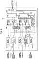
- Fig. 1 is a block diagram of the optical disk recording/reproducing device according to the present invention. In Fig. 1, 1 is an optical disk on which data (information) are recorded in the form of pits. The optical disk recording/reproducing device generally includes a read/
write head 2 for reading or writing information, and a control unit (not shown) for controlling the entire device including driving of the read/write head 2 and rotation of theoptical disk 1. The recording/reproducing device further includes arecording unit 6 for converting the information to be recorded or written into the signal to be recorded on the optical disk and supplying it to the read/write head 2, and a reproducingunit 12 for reproducing the information on the basis of the signal reproduced from theoptical disk 1 by thehead 2. - Now it should be noted that the arrangement according to this embodiment is sectioned as mentioned above for only convenience of explanation as in other embodiments, and may be sectioned in the other manner. Also it should be noted that the names such as the read/write head is labelled for convenience of explanation, and the arrangement of the data (information) recording/reproducing device is not limited by these names.
- Recorded on the
optical disk 1 are data in such a manner that mirror-like non-recorded areas are irradiated with light beams to form pits so that pits patterns indicative of status transitions corresponding to the lengths of the pits are formed. Data may be also recorded on an opto-magnetic disk by forming recording domains with different magnetization directions on the non-recorded areas of the opto-magnetic disk. - It should be noted that in this embodiment, the leading edge and the trailing edge of each of the status transition patterns such as pits correspond to the positions of '1' of the recorded data, namely to the inverted positions of '1' in the run-length-limited code.
- The read/
write head unit 2 is composed of alaser light source 3 for irradiating theoptical disk 1 with a pulse-like light beam, alight receiving part 4 for detecting the signal of the light beam reflected from theoptical disk 1, apre-amplifier 5 for amplifying the signal detected by the light receiving part to produce the signal to be used for reproduction of information, and a circuit 11 for driving thelaser light source 1. It should be noted that thepre-amplifier 5 also produces control signals for focusing control, tracking control, etc. - Further, the read/
write head unit 2 is provided with necessary functions corresponding to the storing manner of thedisk 1. For example, in the case of the opto-magnetic disk, the read/write head unit 2 is provided with a magnetic head for write and a driving circuit therefor (both not shown). - The
recording unit 6 is composed of amodulation circuit 7 for converting the information to be recorded into the record data in the run-length-limited code in accordance with a predetermined conversion rule, e.g. 2-7 (two-to-seven) modulation, a syncsignal storing circuit 8 for previously storing a sync signal to be inserted in the record data, aswitching circuit 9 for inserting the stored sync signal in a predetermined position of the record data in accordance with a prescribed format, and an NRZI (non-return-to-zero-inverted)circuit 10 for NRZI-converting the record data. - The
recording unit 6 and a part of the read/write head unit 2 constitute means for recording data on the recording medium. The syncsignal storage circuit 8 and theswitching circuit 9 constitute sync signal inserting means. - The sync
signal storage circuit 8 stores at least a sync signal (hereinafter also referred to as a RESYNC pattern) for re-synchronization (RESYNC) inserted every prescribed data length in the data area, and can also store another sync signal (hereinafter also referred to as a VFOSYNC pattern) for reproducing clock synchronization (VFOSYNC). Preferred examples of the RESYNC patterns will be described later. - The
NRZI conversion circuit 10 is constructed of e.g. a T (toggle) flip-flop circuit (not shown). Specifically, theNRZI conversion circuit 10 serves to invert the output level ('1' or '0') whenever '1' of the record data converted into the run-length-limited code is input to its input terminal, thereby NRZI converting an input data. - The
reproduction unit 12 is composed of a reproducedsignal separation circuit 13 for separating the reproduced signal detected by the read/write head unit 2 into a leading edge detection signal of the pulse corresponding to the leading edge position of the status transition pattern and a trailing edge detection signal of the pulse corresponding to the trailing edge position,clock synchronization circuits pattern detecting circuits data composing circuit 18 for composing the leading edge data and the trailing edge data using the synchronous signals for re-synchronization, and ademodulation circuit 19 for demodulating the composed reproduced data. - The read part of the read/
write head unit 2 and thereproduction unit 2 constitute means for reproducing the data from the recording medium. - The reproduced
signal separation circuit 13, the internal details of which are not shown, is constructed of a circuit for detecting the signal representing if the edge at issue is a leading edge or a trailing edge on the basis of the reproduced signal alternating between an H (high) level and a L (low) level, and a circuit for separating the signal indicative of the detected leading edge and that indicative of the detected trailing edge and outputting them. - The
clock synchronization circuits - The
pattern detecting circuits - As the RESYNC detection patterns, ones separated from a code train constituting a sync signal in such a manner that they have a bit of '1' disposed alternately and complementarily, such as
patterns - These
patterns pattern detecting circuits pattern detecting circuits - Although the
pattern detecting circuits - The reproduced
data composing circuit 18, as shown in Fig. 4, is made up of a register A48 for taking in leadingedge data 43 in accordance with a reproduction clock VFOCLK1 and sequentially storing them at specified addresses, a register B48 for taking in leadingedge data 44 in accordance with a reproduction clock VFOCLK2 and sequentially storing them at specified addresses, anaddress control circuit 50, reset by the leading edgeRESYNC detection signal 45, for sequentially setting addresses starting fromaddress 0 to designate the addresses for register A48, and anaddress control circuit 51, reset by the trailing edgeRESYNC detection signal 46, for sequentially setting addresses starting fromaddress 0 to designate the addresses forregister 49. - The reproduced
data composing circuit 18 also comprises aselector 53 for sequentially taking in the contents of the register A48 from the designated address and serially outputting them, aselector 54 for sequentially taking in the contents of the register B49 in the same manner and serially outputting them, a register A, Boutput control circuit 52 for designating the same addresses for theselectors RESYNC detection signal 45 and the trailing edgeRESYNC detection signal 46 and causing theselectors OR gate 55 for logic-ORing the outputs from theselectors - The registers A48 and B49 constitute means for individually temporarily storing the leading edge data and the trailing edge data.
- The
address control circuits selectors output control circuit 52 and theOR gate 55 constitute means for composing data. - The
reproduction unit 12 can correct a variation between the leading edge data and the trailing edge data for the VFOSYNC as well as RESYNC by constructing thepattern detecting circuits - Further, using the fact that the position of RESYNC signal is set at regular intervals, the
pattern detection circuits pattern detecting circuits - Further, the
reproduction unit 12 may be constructed to permit the reproduced data to be composed only when the RESYNC signals are detected in bothpattern detection circuits - Explanation will be given for an example of the sector format for composing the reproduced data.
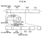
- Fig. 14 shows the sector format formed on a certain track on the optical disk. The optical disk includes a large number of tracks previously formed in a spiral form for example. Each of the tracks is divided into plural (e.g. 64) blocks or sectors.
- Each of the sectors is divided into a
preformat area 400 and adata area 401. Thepreformat area 400 is further classified into asector mark 410 indicative of the start of the sector, a VFOSYNC pattern 411 for creating reproduction clocks, anaddress area 412 where a track address and a sector address are recorded, etc. - User data are recorded within the
data area 401. The format of thedata area 401 is composed of aVFOSYNC pattern 420, a user data demodulation starting pattern 421, theuser data 422 andRESYNC patterns 423 for re-synchronization of the reproduction clock. - Now referring to Figs. 2 to 3B, explanation will be given for an example of the RESYNC pattern.
- Fig. 2 shows a conversion rule of a 2 - 7 code which is an example of the run-length-limited code. Original data on the left hand in Fig. 2 are converted into the code trains on the right hand, respectively. As understood from any combination of the code trains in Fig. 2, the number of successive "0"'s between "1" and "1" is two in minimum and seven in maximum.
- A code train which is not included in the conversion rule of Fig. 2 is the code train in which the code of only two successive "0"'s of the minimum run-length follows immediately after the code of seven successive "0"'s of the maximum run-length. The reason therefor is as follows. Each code train in Fig. 2 has two or three successive "0"'s in the last whereas the original data providing four successive "0"'s in the first is only "0011". Therefore, the code train having seven successive "0"'s is only the case where the code train "00001000" whose original data is "0011" follows immediately after the code train having three successive "0"'s in the last. However, the code train "0000100" has three successive "0"'s in the last. Thus, the code train in which only two successive "0"'s follow immediately after seven successive "0"'s cannot be formed by the conversion rule of Fig. 2.
- As understood from the above description, an example of the synchronous signal constituting the RESYNC pattern may be a code including repetition of the code train in which the code of only two successive "0"'s of the minimum run-length follows immediately after the code of seven successive "0"'s of the maximum run-length.
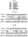
- An example of sync signal according to the above idea is shown in Fig. 3A.
- The
sync signal 24 shown in Fig. 3 includes a twice repeated code train of two successive "0"'s immediately after a twice repeated code train of seven successive "0"'s (arrow B), and its bit number is two bytes of the record data before the conversion into the run-length-limited code. - When the
sync signal 24, after NRZI converted, is recorded on theoptical disk 1 in the form of pits, a pit pattern representative of status transitions is created. 29 to 31 denote length pits. - Further, the
pit pattern 25 will be inverted in accordance with its state immediately before thesync pattern 24 is inserted. Specifically, if any pit is extended to before thepit 29 in thepit pattern 25, any pit will not be located at the positions of thepits pits pits pit 31. Now, the case of thepit pattern 25 shown will be explained; if the pits are inverted, aleading edge data 26 and a trailingedge data 27 will be replaced by each other. - Outputs from the reproduced
signal separation circuit 13 reading out thepit pattern 25 are theleading edge data 26 and the trailingedge data 27. - The
leading edge data 26 includes 15 successive "0" from the first "1" (arrow D) to the second "1" (arrow E). However, the 2 - 7 code includes only 7 (seven) successive "0"'s in maximum so that it includes "1" of the trailingedge data 27 in the just middle from the first "1" (arrow D) to the second "1" (arrow E) of theleading edge data 26. Thus, it can be decided only from theleading edge data 26 that thesync signal 24 includes the twice repeated code of seven successive "0"'s. - Further, the leading
edge data 26 includes 5 (five) successive "0"'s from the second "1" (arrow E) to the third "1" (arrow F). However, the 2 - 7 code includes only 2 (two) successive "0"'s in minimum so that it includes "1" in the trailingedge data 27 in the just middle from the second "1" to the third "1" of theleading edge data 26. Thus, it can be decided only from theleading edge data 26 that thesync signal 24 also includes the twice repeated code of two successive "0"'s. - Accordingly, it can be decided only by the
leading edge data 26 that thesync signal 24 is a sync signal with a code train not included in the conversion rule into the 2 - 7 code in which only two successive "0"'s follows after seven successive "0"'s. - In the case where the
pit pattern 25 as shown in Fig. 3A is inverted, thesync signal 24 can be detected from its trailingedge data 27. - In this way, it can be decided only by the
leading edge data 26 or the trailingedge data 27 that thesync signal 24 as shown in Fig. 3A is a sync signal (resync pattern). It is needless to say that thesync signal 24 can be detected using both leading edge data and trailing edge data. - The reproduced
data composing circuit 18 as shown in Fig. 1, in response to that thesync signal 24 has been detected, composes theleading edge data 26 and the trailingedge data 27 delayed so that the respective "1"'s are located at predetermined (registered as a sync signal) positions of the time base. - Explanation will be given for a further improved pattern of the sync patten of Fig. 3A.
- Laser light is used in order to create pits of recording domains on the
optical disk 1. For this reason, if the place where seven successive "0"'s continue is a pit or a recording domain, that place will be irradiated with the laser light for a relatively long time. Thus, its circumference will be warmed so that the resultant pit or recording domain having a larger size than the required size can be created. - Specifically, if the place between "1" indicated by arrow A and "1" indicated by arrow B in the
sync signal 24 shown in Fig. 3A constitutes a pit or recording domain, the trailing edge of the pit (recording domain) corresponding to "1" indicated by arrow B can slightly lag so the pit can also be slightly extended. Also, the leading edge of pit (recording domain) corresponding to "1" indicated by arrow C can slightly precede. - As a result, the place between "1" indicated by arrow B and "1" indicated by arrow C, which does not a pit (recording domain), will be slightly shortened. This can make it impossible to reproduce "1"'s indicated by arrows B and C. The reproduction of "1"'s indicated by arrows B and C can be assured by reducing the recording density so that the distance between "1" and "1" is much longer than the degree shortened owing to warming by the laser light.
- However, reducing the recording density is not desirable for the sync signal. The recording density should be determined considering if the code train in which 3 (three) successive "0"'s follows after 7 (seven) successive "1"'s, the most difficult to reproduce in the conversion rule into the 2 - 7 code included in the data to be recorded, can be reproduced. Also, the sync signal should be patterned so that it can be reproduced with that recording density.
- To this end, the pattern as shown in Fig. 3B is proposed. This pattern intends to prevent the above short non-pit place from being further shortened owing to partial temperature increase in the optical disk by irradiation of the laser light to make it impossible to be reproduced.
- In Fig. 3B, 24 is the sync pattern code train constituting a resync pattern, 25 is a pit pattern on the optical disk corresponding to the
sync signal pit pattern 25. - In the sync signal shown in Fig. 3B, the position of "1" indicated by arrow A in the sync signal shown in Fig. 3A is shifted to the position of "1" indicated by arrow A2.
- Thus, 6 (six) successive "0"s continue before the code consisting of 2 (two) successive "0"'s. The code train thus formed can be realized by the conversion rule shown in Fig. 2. Therefore, it can be reproduced without reducing the recording density.
- Even if the place corresponding to 8 (eight) successive "0"'s constituting before the code consisting of 6 (six) successive "0"'s, which is a pit, is partially warmed so as to slightly enlarge the size of the pit, any problem does not occur since the subsequent 6 successive "0"'s have only to be reproduced.
- The trailing edge data obtained by reproducing the
sync signal 24, recorded in the form of thepit pattern 25, is equivalent to theleading edge data 26 as shown in Fig. 3A. Therefore, as described in connection with the sync signal shown in Fig. 3A, it can be detected that the signal (resync pattern) not existing in the conversion rule into the 2 - 7 code. - Also in the case of Fig. 3B, the
pit pattern 25 may be inverted. Then, it can be decided from theleading edge data 26 that thesync signal 24 is a sync signal. In this way, thesync signal 24 as shown in Fig. 3B can be detected as a sync signal only from theleading edge data 26 or the trailingedge data 27, and also it is not necessary to reduce the recording density. - Now referring to Figs. 5A and 5B as well as the respective figures explained above, explanation will be given for the operation of this embodiment. It should be noted that the explanation will be mainly made on the resync operation.
- First, the operation of recording information (data) will be explained.
- As seen from Fig. 1, the information to be recorded or written is input to the
modulation circuit 7. Themodulation circuit 7 converts the input information into a run-length-limited code (a 2 - 7 code in this embodiment) on a predetermined conversion rule. The information converted into the run-length-limited code is input to theNRZI circuit 10 via the switchingcircuit 10. - Whenever "1" enters the
NRZI circuit 10, its output is inverted to be NRZI-converted. The information converted into the run-length-limited code and NRZI-converted is converted into a laser light pulse by means of a laser light source driving circuit 11 and thelaser light source 3. Thus, as seen from Fig. 5A, in accordance with awrite signal 38, the pits or recording domains as shown by apit pattern 39 are created and recorded on theoptical disk 1. - As shown by the
format 36 in Fig. 5A, a sync signal is inserted in the recorded information at its predetermined regular intervals. Specifically, the sync signal, which is a predetermined code train (shown in Fig. 3B) previously stored in thememory 8, is inserted in the information to be recorded via theswitching circuit 9 at regular intervals (e.g. 20 bytes) and input to theNRZI conversion circuit 10 with the information. During this operation, the operation of theconversion circuit 7 and inputting of the information to be recorded are stopped. - In this way, the information and the sync signals are recorded on the
optical disk 1. - The operation of reproducing the recorded information will be described below.
- The laser light whose intensity is lower than it is in the recording is emitted from the
laser light source 3 and radiated to theoptical disk 1. Thelight receiving unit 3 detects the intensity of the reflection light or the rotation of the polarized light surface due to the presence of the pit (recording domain) on theoptical disk 1. The detected signal is amplified by thepreamplifier 5, and a reproducedsignal 40 is produced and sent to the reproducedsignal separation circuit 13. - The reproduced
signal separation circuit 13 generates a leading edge detection signal and a trailing edge detection signal from the rising edge and the falling edge of the signal produced from thelight receiving unit 4, respectively. The leadingedge detection signal 41 and the trailingedge data 42 enter theclock synchronization circuits leading edge data 43 and trailingedge data 44 are sent to the reproduceddata composing circuit 18 and thepattern detection circuits - The
pattern detection circuits leading edge data 43 with the RESYNC one-edge detection pattern 1, and the trailingedge data 44 with the RESYNC one-edge detection pattern 45, respectively (both one-edge patterns are shown in Fig. 5B). Thepattern detection circuit 16 produces aRESYNC detection signal 45 for theleading edge data 43 when the part a of the leading edge data as shown in Fig. 5A agrees with thedetection pattern 1. Likewise, thepattern detection circuit 17 produces aRESYNC detection signal 46 for the trailingedge data 44 when the part b of the trailing edge data as shown in Fig. 5A agrees with thedetection pattern 2. - These RESYNC detection signals 45 and 46 are sent to the corresponding
address control circuit RESYNC detection signal 45 is output earlier than theRESYNC detection signal 46, theaddress control circuit 50 is reset earlier than theaddress control circuit 51. Therefore, first, theaddress control circuit 50 produces successively the addresses fromaddress 0 in accordance with the reproduction clock VFOCLK1. Next, theaddress control circuit 51 produces successively the addresses fromaddress 0 in accordance with the reproduction clock VFOCLK2. - The register A48 stores the
leading edge data 43 after the RESYNC pattern at the address designated by theaddress control circuit 50 in synchronism with the reproduction clock VFOCLK1. A little later, likewise, the register B49 stores the trailing edge data at the designated address in synchronism with the reproduction clock VFOCLK2. - In terms of the common addresses produced by the register A, B
output control circuit 52, theselectors OR gate 55 to be composed. - Thereafter, the
address control circuits leading edge data 43 and the trailingedge data 44, for data composition, respectively. - As described above, in this embodiment, the RESYNC pattern is detected by only the edge of each of the
leading edge data 43 and thetraining edge data 44. Therefore, even if there is some change in the distance between the leading edge and the trailing edge in the pit pattern, less change in the distance between the leading edges or between the trailing edges results. Thus, the positions of the edges in the pit pattern can be precisely detected. Further, in accordance with this embodiment, relative deviation in the positions of the encoded bits between theleading edge data 43 and the trailingedge data 44 is corrected by taking a logical sum of theleading edge data 43 and the trailingedge data 44 which are once stored in the registers A48 and B49 as buffers and simultaneously outputted in their bit-correspondence. - Explanation will be made on other embodiments of the sync signal which can be used in the present invention, and another embodiment of the optical disk recording/reproducing device which is suitable to use such sync signals. The same construction and operation as described previously will not be explained.
- Fig. 6 shows formats of two kinds of sync signals 61 and 62, the corresponding pit pattern, leading edge data and trailing edge data.
- The sync signals 61 and 62 shown in Fig. 6 are changed in accordance with the presence of a pit at the position immediately before the sync signal at issue is inserted. Specifically, if there is the pit 630 (recording domain) created on an optical disk at the position immediately before the sync signal is inserted, the
sync signal 61 is recorded. If there is not the pit at that position, thesync signal 62 is recorded. - The
sync signal 61 is different from thesync signal 62 in that "1" is located at thethird bit position 610. If the pit (recording domain) is created at the position immediately before the sync signal is inserted, creation of the pit is ceased by the third bit "1". - Both sync signals 61 and 62 include a code train in which two successive "0"'s are twice repeated immediately after seven successive "0"'s are twice repeated, as shown in Fig. 3A. However, the presence of the pit (recording domain) corresponding to the above code train is fixed irrespective of the state immediately before the sync signal is inserted, as illustrated by the
pit patterns - Therefore, unlike the sync signal shown in Fig. 3A, the
pit patterns - Further, it can be decided from the state where five "0"'s continue after fifteen "0"'s continue that the
sync signal - Further, in the sync signals 61 and 62 shown in Fig. 6, the state where five "0"'s continue after fifteen "0"'s continue appears only in the
leading edge data - Explanation will be made on an embodiment of the optical disk data recording/reproducing device which is suitable to record/reproduce data using the above sync signals 61 and 62 as RESYNC patterns.
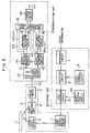
- Fig. 7 is a block diagram of the arrangement of such as optical disk data recording/reproducing device. This optical disk recording/reproducing device, as in the device as shown in Fig. 1, an optical read/
write head unit 2 used to record/reproduce information for anoptical disk 1, a recording (writing)unit 6 for supplying the data to be written to theoptical head unit 2, and areproduction unit 12 for reproducing the information from the signal reproduced signal detected by theoptical head unit 2. - In Fig. 7, like reference numerals refer to like parts in Fig. 1 so that the differences therebetween will be mainly explained.
- The
optical head unit 2 is made up of, in the same arrangement as Fig. 1, thelaser light source 3, thelight receiving unit 4, thepreamplifier 5 and the laser light source driving circuit 11. - The recording (writing)
unit 6 is made up of, in the same arrangement as Fig. 1, a syncsignal designation circuit 33 as well as themodulation circuit 7, the syncsignal storage circuit 8, the switchingcircuit 9 and theNRZI conversion circuit 10. - The
storage circuit 8 stores the sync signals 61 and 62 having the patterns as shown in Fig. 6 as RESYNC patterns. Thestorage circuit 8 can store VFOSYNC patterns as described in connection with Fig. 1. - The sync
signal designation circuit 33 detects the output from the NRZI conversion circuit immediately before the sync signal is inserted to select one of the sync signals 61 and 62 in thestorage circuit 8 according as the output is in the state of creating the pit (recording domain) or not. - The
reproduction unit 12 is made up of, in the same arrangement as Fig. 1, a reproducedsignal separation circuit 13,clock synchronization circuits pattern detection circuits data composing circuit 18 and thedemodulation 19. However, as seen from Fig. 9, the reproduceddata composing circuit 18 is different, from that (Fig. 4) in Fig. 1 in that adelay circuit 56b is added to the previous stage of theaddress control circuit 50; a one-shot multivibrator 57, a delay circuit 58 and an ANDgate 59 are added to the previous stage of theaddress control circuit 51; andfurther delay circuits - This is because the two kinds of sync signals 61 and 62 as shown in Fig. 6 are used so that the leading edge data permits the RESYNC pattern discriminatable from the other data to appear whereas the trailing edge data only permits the RESYNC pattern to be detected but does not permit it to be surely discriminated from the other data.
- In this embodiment, the
delay circuits shot multivibrator 57 produces a pulse having the pulse width which is longer than the above delay time. - In such an arrangement, the leading edge data and the trailing edge data are output from the
corresponding delay circuits corresponding delay circuits - Now when the leading edge data RESYNC detection signal is input in the state deviated before or after input of the trailing edge data RESYNC detection signal, the one-
shot multivibrator 57 produces a pulse. Therefore, the logical product of this pulse and the output from thedelay circuit 58b taken by the ANDgate 59 will consider the trailing edge data RESYNC detection signal to be correct. - The RESYNC detection signal is produced also when the data having the same pattern as the RESYNC pattern is detected by the
pattern detection circuit 17. However, in this case, the leading edge data RESYNC detection signals are not before and after the data so that this RESYNC detection signal is stopped by the ANDgate 59 thereby to prevent the rear stageaddress control circuit 51 from being reset. - Further, all the leading edge data, the trailing edge data and their RESYNC detection signals are delayed by the same time so that relative deviation between the leading edge data and the trailing edge data is held as it is, which will be corrected by the rear stage registers A48 and B49. This correction operation is the same as in the embodiment described in connection with Fig. 1.
- The device according to this embodiment operates in the same way as that described in connection with Fig. 1 except the differences described above, thereby recording the information including the sync signals 61 and 62 as shown in Fig. 6 as RESYNC patterns on the
optical disk 1 and reproducing it therefrom. - Referring to Fig. 8, Explanation will be made on another embodiment of the optical disk recording/reproducing device which is suitable to use the above sync signals 61 and 62 as RESYNC signals.
- The device according to this embodiment, which is made up of an
optical disk 1, an optical read/write head unit 2, a recording (writing)unit 6 and areproduction unit 12, is constructed and also operates in the same way as the device described in connection with Fig. 7 although it is partially different from the latter in the detailed arrangement of therecording unit 18. Only the differences will be described below. - The
recording unit 6 in this embodiment is made up of areset designation circuit 34 as well as themodulation circuit 7, the syncsignal storage circuit 8, the switchingcircuit 9 and theNRZI conversion circuit 10. - In this embodiment, the
storage circuit 8 stores only thesync signal 62 as shown in Fig. 6 as a RESYNC pattern. It is needless to say that thestorage circuit 8 may also store the VFOSYNC patterns. - The
reset designation circuit 34 serves to designate reset for theNRZI conversion circuit 10 at the third bit position starting from the insertion of thesync signal 52 by the switchingcircuit 9. Thus, if the output from theNRZI conversion circuit 10 is in the state of creating a pit (recording domain), theNRZI conversion circuit 10 is reset thereby to cease the creation of the pit (recording domain). This has the same meaning as that the sync signal is recorded as a sync signal. On the other hand, if the above output is not in that state, the output does not change by resetting theNRZI conversion circuit 10. Thus, thesync signal 62 is recorded as a sync signal. - In this way, the
sync signal - Further, recording the sync signal shown in Fig. 3A may require to reduce the recording density as the case may be, whereas recording the
sync signal - Now referring to Fig. 10, explanation will be made on an embodiment of the reproduced data composing circuit which is preferably used for the reproduction unit of the data recording/reproducing device in which a RESYNC pattern is detected by a leading edge data and/or a trailing edge data, as in the embodiment shown in Fig. 1.
- The reproduced
data composing circuit 18 according to this embodiment, like thecircuit 18 shown in Fig. 4, is made up ofaddress control circuits output control circuit 52,selectors OR gate 55. These components will not be explained here since they have been already described. - The reproduced
data composing circuit 18 according to this embodiment is made up of, as its characteristic components,delay circuits shot multivibrator 57 which produces the pulse with a pulse width longer than the delay time, ANDgates RESYNC detection circuit 60, in response to the RESYNC detection signals for the leading edge data and the trailing edge data which are received within a fixed time difference, produces a leading/trailing edge RESYNC detection signal to activate themultivibrator 57. - The leading edge data
RESYNC detection signal 45 passing through thedelay circuit 56b is ANDed with the output pulse from the one-shot multivibrator 57 in the ANDgate 59a. Likewise, the trailing edge dataRESYNC detection signal 46 passing through thedelay circuit 58b is ANDed with the output pulse from the one-shot multivibrator 57 in the ANDgate 59b. Thus, only if the RESYNC detection signals are detected for both leading edge data and trailing edge data, these detection signals 45 and 46 are valid. - Therefore, even if the RESYNC pattern is erroneously detected on the side of the leading edge or the trailing edge, an erroneous resync operation can be prevented. Particularly, if the RESYNC which is not necessarily unique appears on either side of the leading edge data and the trailing edge data, the reproduced
data composing circuit 18 according to this embodiment is preferably used. - Specifically, if it can be decided that the SYNC pattern includes the code train not existing in the conversion rule into the run-length-limited by either leading edge data or trailing edge data in accordance with the status transition pattern (pit pattern), even if this fact cannot be decided by the other edge data, the re-synchronization can be carried out by use of the reproduced data composing circuit according to this embodiment.
- Incidentally, the reproduced data composing circuit which can be used in the present invention should not be limited to those proposed in the embodiments previously described and in this embodiment. For example, the arrangement using FIFO memories in place of the registers may be adopted. In short, any circuit construction may be adopted as long as the relative position between the leading edge data and the trailing edge data can be corrected.
- Other examples of the sync signal which can be used for the present invention will be described below.
- The sync signal shown in Fig. 11 adopts a 2 - 7 code as a run-length-limited code.
- With the number of "1"'s being fixed to 3 in the 2 - 7 code, the longest total run-length is provided by the following code train:
"10000000100000001" - The sync signal shown in Fig. 11 includes a code train
"100000000100000001" - This code train is longer than the sync signal of Fig. 3A in which seven successive "1"'s are twice repeated in the 2 - 7 code since it includes an equal number of "1"'s to, but a larger number of "0"'s by one than the latter.
- The leading edge data 73 (trailing
edge data 74 as the case may be) obtained when reproducing the code train recorded on the optical disk as shown in Fig. 11 includes the state where 16 (sixteen) successive "0"'s continue. Therefore, this recorded sync signal includes the code consisting of 8 (eight) successive "0"'s not existing in the 2 - 7 code conversion rule so that it can be discriminated from the other code train due to the 2 - 7 code conversion rule. - The
pit pattern 72 shown in Fig. 11, like the pit pattern as shown in Figs. 3A and 3B, may be inverted in accordance with the state immediately before the sync signal is inserted. However, the sync signal of Fig. 11 includes the code consisting of 3 (three) or more successive "0"'s following after the code consisting of 7 (seven) or more successive "0"'s. Therefore, using the sync signal as shown in Fig. 3A may be required to reduce the recording density whereas using the sync signal of Fig. 11 is not required to reduce it by any means. - Incidentally, in accordance with the same idea as illustrated in Fig. 11, it is possible to use a code train in which the number of inversions, i.e. "1" is equal to that in the combined code train providing the minimum total run-length in the run-length-limited code and whose length is shorter than the latter code train.
- Although the sync signal described above uses the 2 - 7 code, the other run-length-limited code can be used in the present invention in accordance with the same idea.
- Fig. 12 shows the conversion rule into a 1 - 7 (one to seven) code.
- The bits indicated by x in the code train of Fig. 12 depend on the value of the previous bit when being combined with the other code train. If the previous bit is "1", x is "0", and if the previous bit is "0", x is "1".
- In the 1 - 7 code, the number of "0"'s between "1" and "1" is set for 1 to 7, and also two bits of the data are converted into three bits in the code train.
- Fig. 13 shows an example of the sync signal in the form of the 1 - 7 code.
- This sync signal is constructed in the same manner as the sync signal in the form of the 2 - 7 code as shown in Fig. 1. With the number of "1" set for 3 (three), the most longest total run-length is provided by the following code trains
- a. "100000010000001"
- b. "100000001000001"
- c. "100000100000001"
- The
sync signal 81 shown in Fig. 13 includes the code train
"1000000010000001" This code train is longer than the above code trains a to c since it includes an equal number of "1"'s to but a larger number of "0"'s by one than the latter code trains. - The leading edge data 83 (trailing
edge data 84 as the case may be) obtained when reproducing the code train recorded on the optical disk as shown in fig. 13 includes the state where 14 (fourteen) successive "0"'s continue. Therefore, the sync pattern recorded includes a combination of 7 (seven) successive "0"'s and 6 (six) successive "0"'s with "1" intervening therebetween or a code train consisting 8 (eight) or more successive "0"'s which is a code train not existing in the conversion rule into the 1 - 7 code. Thus, it can be decided that this pattern is a sync signal. - The
pit pattern 82 shown in Fig. 13, like the pit pattern as shown in Fig. 11 may be inverted in accordance with the state immediately before the sync signal is inserted. In this case, the 1 - 7 code includes a code train in which only one "0" follows immediately after 7 (seven) successive "0"'s. Therefore, using the code train in which only 2 (two) "0"'s follow after 6 (six) successive "0"'s as shown in Fig. 13 is not required to reduce the recording density unlike using the 2 - 7 code described in connection with Fig. 3A. - The code trains of the sync signals hitherto described are exemplary. The present invention should not be limited to these code trains and can use the other code trains in accordance with the same idea.
- In the embodiments shown in Figs. 1, 7 and 8, serial data are dealt with. The present invention, however, should not be limited to such a way. For example, the reproduction unit can be constructed so that it converts the serial data into parallel data, and thereafter detects sync signals and composes the data.
- Further, although the data recording/reproducing device described according to the above embodiments carry out both recording and reproducing data, it may be constructed so that the recording unit and reproducing unit are separated.
Claims (12)
- Device for recording information on an optical recording medium, comprising:modulation means (7) for converting the information to be recorded into recording data in the form of a run-length-limited code in accordance with a predetermined conversion rule;storage means (8) for storing a synchronization (=sync) signal to be inserted into said recording data wherein the writing pattern for the sync signal is a pattern that cannot be generated from the information to be recorded,switching means (9) for inserting the sync signal in accordance with a predetermined format; anda NRZI-conversion means (10) for NRZI-converting the recording data and the inserted sync signals,writing means (2) for writing a pattern (25) of changed physical status on recording medium on the basis of the NRZI-converted recording data,characterized in thatthe storage means (8) stores a sync bit pattern (24 in Fig. 3A) which comprises a predetermined sequence of minimum and maximum run-lengths and which leads, when not inverted before recording, to an NRZI-converted andrecorded pattern (25) whereby bit intervals of the reproduced leading edge signal (26) cannot be derived from RLL codes for data and, when inverted before recording, to an NRZI-converted and recorded pattern whereby bit intervals of the reproduced trailing edge signal (27) cannot be derived from the RLL codes, inverting being in response to the presence of a deformed or transition-changed area (28 in Fig. 3B) before the sync signal.
- A device for recording information on an optical recording medium, comprising:modulation means (7) for converting the information to be recorded into recording data in the form of a run-length-limited code in accordance with a predetermined conversion rule;storage means (8) for storing a synchronization (=sync) signal to be inserted into said recording data wherein the writing pattern for the sync signal is a pattern that cannot be generated from the information to be recorded,switching means (9) for inserting the sync signal in accordance with a predetermined format; andan NRZI-conversion means (10) for NRZI-converting the recording data and the inserted sync signals,writing means (2) for writing a pattern (25) of changed physical status on recording medium on the basis of the NRZI-converted recording data,characterized in thatthe storage means (8) stores sync bit pattern (61, 62 in Fig. 6) which comprises a predetermined sequence of minimum and maximum run-lengths and which leads to an NRZI-converted and recorded pattern (63, 64) whereby bit intervals of one of the reproduced leading edge and trailing edge signal (65, 67, 66, 68) cannot be derived from RLL codes for data, a bit (610) near the beginning of the sync pattern being changed in accordance with the presence of a deformed or transition-changed area (630) before the sync signal.
- Device for recording information on an optical recording medium, comprising:modulation means (7) for converting the information to be recorded into recording data in the form of a run-length-limited code in accordance with a predetermined conversion rule;storage means (8) for storing a synchronization (=sync) signal to be inserted into said recording data wherein the writing pattern for the sync signal is a pattern that cannot be generated from the information to be recorded,switching means (9) for inserting the sync signal in accordance with a predetermined format; andan NRZI-conversion means (10) for NRZI-converting the recording data and the inserted sync signals,writing means (2) for writing a pattern (25) of changed physical status on recording medium on the basis of the NRZI-converted recording data,characterized in thatthe storage means (8) stores a sync pattern (71 in Fig. 11) which leads to an NRZI-converted and recorded pattern (72) wherein bit intervals of the reproduced edge signals (73, 74) cannot be derived from RLL codes for data, and inverting of the pattern being in response to the presence of a deformed or transition-changed area before the sync signal, the NRZI-converted pattern including a run-length being longer than the maximum run-length.
- A device for reproducing the information recorded on a recording medium (1), according to anyone of claims 1 to 3, comprising:means for detecting signals indicative of positions of the leading edge and trailing edge of the transition-changed pattern recorded on the recording medium;means (13) for separating said detected signals into a leading edge data corresponding to the leading edge of a deformed or transition-changed area and a trailing edge data corresponding to the trailing edge thereof;pattern detecting means (16, 17) storing two kinds of detecting patterns for detecting sync signals inserted in the information recorded on the recording medium on the basis of said leading edge data and said trailing edge data, respectively; andreproduced data composing means (18) comprising storage means (48, 49) receiving leading and trailing edge data (43, 44) and correcting a change in the relative positional relationship between the leading edge data and trailing edge data by addressing the storage positions based on the detected sync signals, and by composing the stored leading edge data and the stored trailing edge data to provide reproduced data.
- A method for recording information on a optical recording medium, comprising the steps ofconverting the information to be recorded into recording data in the form of a run-length-limited code in accordance with a predetermined conversion rule;storing a synchronization (=sync) signal to be inserted into said recording data wherein the writing pattern for the sync signal is a pattern that cannot be generated from the information to be recorded,inserting the sync signal in accordance with a predetermined format;NRZI-converting the recording data and the inserted sync signals, andwriting a pattern (25) of changed physical status on recording medium on the basis of the NRZI-converted recording data,characterized in thata sync bit pattern is stored which comprises a predetermined sequence of minimum and maximum run-lengths and which leads, when not inverted before recording, to an NRZI-converted and recorded pattern wherein bit intervals of the reproduced leading edge signal cannot be derived from RLL codes for data and when inverted to an NRZI-converted pattern wherein bit intervals of the trailing edge signal cannot be derived from the RLL codes, inverting being in response to the presence of a deformed or transition-changed area before the sync signal.
- A method for recording information on a optical recording medium, comprising the steps ofconverting the information to be recorded into recording data in the form of a run-length-limited code in accordande with a predetermined conversion rule;storing a synchronization (=sync) signal to be inserted into said recording data wherein the writing pattern for the sync signal is a pattern that cannot be generated from the information to be recorded,inserting the sync signal in accordance with a predetermined format;NRZI-converting the recording data and the inserted sync signals, andwriting a pattern (25) of changed physical status on recording medium on the basis of the NRZI-converted recording data,characterized in thata sync bit pattern is stored which comprises a predetermined sequence of minimum and maximum run-lengths and which leads to an NRZI-converted and recorded pattern wherein bit intervals of one of the reproduced leading edge and trailing edge signal cannot be derived from RLL codes for data, a bit near the beginning of the sync pattern being changed in accordance with the presence of a deformed or transition-changed area before the sync signal.
- A method for recording information on an optical recording medium, comprising the steps ofconverting the information to be recorded into recording data in the form of a run-length-limited code in accordance with a predetermined conversion rule;storing a synchronization (=sync) signal to be inserted into said recording data wherein the writing pattern for the sync signal is a pattern that cannot be generated from the information to be recorded,inserting the sync signal in accordance with a predetermined format;NRZI-converting the recording data and the inserted sync signals, andwriting a pattern (25) of changed physical status on recording medium on the basis of the NRZI-converted recording data,characterized in thata bit sync pattern is stored which leads to an NRZI-converted and recorded pattern wherein bit intervals of the reproduced edge signals cannot be derived from RLL codes for data, an inverting of the pattern being in response to the presence of a deformed or transition-changed area before the sync signal, the NRZI-converted pattern including a run-length being longer than the maximum run-length.
- A method according to claim 5 or 6,
characterized in that
in the case where a code trains (MN) being a combination of a code train (M) with either the maximum or the minimum run-length in the run-length-limited code and a code train (N) having the other of minimun or maximum run-length in the run-length-limited code, is not included in the conversion rule of convertinq information into a run-length-limited code as said sync signal a sync signal is used which includes a code train (M...MN...N) comprising repetitions of the minimum or maximum run-length code train (N) immediately after repetitions of the maximum or minimum run-length code train (M). - A method according to claim 5,
characterized in that
in the case where a code train (MN) being a combination of a code train (M) with a maximum run-length in the run-length-limited code and a code train (N) with a minimum run-lengthin the run-length-limited code, is not included in the conversion rule of converting information into a run-length-limited code, as said sync signal a sync signal is used which includes a code train (LSN...N) comprising repetition of the minimum run-length code train (N) immediately after a code train (LS) which is a combination of a code train (L) having a length longer than the maximum run-length code train (M) and a code train (S) having a length shorter than the minimum run-length code train (N) and has a length equal to an integer multiple of the maximum run-length code train (M). - A method according to claim 6,
characterized in that
a first sync signal and a second sync signal as said sync signal are changed according to the status of the place immediately before the place where the sync signal is to be inserted, and said first sync signal is not included in the conversion rule of converting information into the run-length-limited code and has a first code train with an odd number of intermediate inverted code(s), and said second sync signal is also not included in the conversion rule of converting information into the run-length-limited code and has no intermediate inverted code or has an even number of inverted codes. - A method according to claim 5,
characterized in that
said run-length-limited code is a 2 - 7 (two-to-seven) code, and said sync signal includes either of the following code trainsa. "10000000100000001001001"b. "10000000010000001001001" - A method according to claim 7,
characterized in that
said sync signal is equal, in the number of its inverted parts, i.e. logic '1's, to that in a code train in which code trains are combined to provide a maximum total run-length in the run-length-limited code, and includes a code train longer or shorter than that code train.
Applications Claiming Priority (2)
| Application Number | Priority Date | Filing Date | Title |
|---|---|---|---|
| JP1249994A JP2534778B2 (en) | 1989-09-26 | 1989-09-26 | Information recording / reproducing system and information recording / reproducing apparatus |
| JP249994/89 | 1989-09-26 |
Publications (3)
| Publication Number | Publication Date |
|---|---|
| EP0420179A2 EP0420179A2 (en) | 1991-04-03 |
| EP0420179A3 EP0420179A3 (en) | 1991-11-27 |
| EP0420179B1 true EP0420179B1 (en) | 1996-07-10 |
Family
ID=17201260
Family Applications (1)
| Application Number | Title | Priority Date | Filing Date |
|---|---|---|---|
| EP90118458A Expired - Lifetime EP0420179B1 (en) | 1989-09-26 | 1990-09-26 | Data recording/reproducing method and device |
Country Status (4)
| Country | Link |
|---|---|
| US (4) | US5229986A (en) |
| EP (1) | EP0420179B1 (en) |
| JP (1) | JP2534778B2 (en) |
| DE (1) | DE69027726T2 (en) |
Cited By (1)
| Publication number | Priority date | Publication date | Assignee | Title |
|---|---|---|---|---|
| US7957370B2 (en) | 1993-02-01 | 2011-06-07 | Lake Cherokee Hard Drive Technologies, Llc | Synchronous read channel |
Families Citing this family (58)
| Publication number | Priority date | Publication date | Assignee | Title |
|---|---|---|---|---|
| JP2534778B2 (en) * | 1989-09-26 | 1996-09-18 | 株式会社日立製作所 | Information recording / reproducing system and information recording / reproducing apparatus |
| US5331620A (en) * | 1990-02-09 | 1994-07-19 | Matsushita Electric Industrial Co., Ltd. | Recording method and recording apparatus for optical disk |
| US5392168A (en) * | 1990-08-31 | 1995-02-21 | Matsushita Electric Industrial Co., Ltd. | Method of recording digital video and audio data |
| EP0570524B1 (en) * | 1991-02-04 | 1996-01-03 | Dolby Laboratories Licensing Corporation | Storage medium and apparatus for recovering information from such medium by oversampling |
| US5615188A (en) * | 1991-02-06 | 1997-03-25 | Matsushita Electric Industrial Co., Ltd. | Recording method and recording and reproducing apparatus for optical disk |
| US5231545A (en) * | 1991-06-04 | 1993-07-27 | Quantum Corporation | Fault tolerant rll data sector address mark decoder |
| JPH05159462A (en) * | 1991-12-03 | 1993-06-25 | Canon Inc | Method for transmitting or recording information, information recording and reproducing device and information transmitting device |
| US5416760A (en) * | 1991-12-16 | 1995-05-16 | Advanced Micro Devices, Inc. | Recovery of data from optical data disk sectors having missing or defective synchronization information |
| DE4304267C2 (en) * | 1992-02-13 | 1997-08-14 | Hitachi Ltd | A method of preparing information for the purpose of writing the information to an optical disk and an optical disk using such a method |
| JPH05282799A (en) * | 1992-04-01 | 1993-10-29 | Sony Corp | Information recording device |
| JP3088844B2 (en) * | 1992-06-03 | 2000-09-18 | パイオニア株式会社 | Digital signal reproduction device |
| JPH06162668A (en) * | 1992-11-24 | 1994-06-10 | Hitachi Ltd | Information recording system |
| US5463606A (en) * | 1992-12-22 | 1995-10-31 | Olympus Optical Co., Ltd. | Optical information reading and reproducing apparatus using pseudo DC-free codes |
| JP3083011B2 (en) * | 1992-12-28 | 2000-09-04 | キヤノン株式会社 | Data recording method and device |
| JP3161858B2 (en) * | 1993-02-05 | 2001-04-25 | 株式会社リコー | Information recording and playback method |
| USRE39832E1 (en) | 1993-03-15 | 2007-09-11 | Matsushita Electric Industrial Co., Ltd. | Optical recording disk capable of resynchronization in digital encoding and decoding |
| JP2863052B2 (en) | 1993-03-15 | 1999-03-03 | 松下電器産業株式会社 | Digital data encoding method, decoding method, encoding device, and decoding device |
| JPH06302042A (en) * | 1993-04-15 | 1994-10-28 | Hitachi Ltd | Magneto-optical disk device |
| US5365382A (en) * | 1993-05-18 | 1994-11-15 | Digital Equipment Corporation | Synchronization to different fields in a storage device |
| US5379161A (en) * | 1993-06-14 | 1995-01-03 | International Business Machines Corporation | Method and system for synchronization character location and prediction in a data storage system |
| JP2920065B2 (en) * | 1994-03-16 | 1999-07-19 | 株式会社東芝 | Data recording method, recording apparatus, reproducing apparatus and reproducing method |
| US6384996B1 (en) * | 1994-10-31 | 2002-05-07 | Samsung Electronics Co., Ltd. | Insertion of ones and zeroes into I-NRZI modulation for magnetic recording apparatus to facilitate head tracking |
| JPH08249831A (en) * | 1995-03-13 | 1996-09-27 | Hitachi Ltd | Information reproducing device |
| JP3621149B2 (en) * | 1995-03-20 | 2005-02-16 | 富士通株式会社 | Synchronization pattern reading method, synchronization pattern detection circuit, address mark detection circuit |
| JP2967333B2 (en) * | 1995-06-12 | 1999-10-25 | 富士通株式会社 | Data playback device |
| JP3394127B2 (en) * | 1995-12-05 | 2003-04-07 | 株式会社東芝 | Digital data transmission method |
| JP3462328B2 (en) * | 1995-12-28 | 2003-11-05 | パイオニア株式会社 | Spindle servo device for optical disk player |
| EP1022736B1 (en) * | 1996-02-08 | 2002-07-03 | Matsushita Electric Industrial Co., Ltd. | Optical disk, optical disk device, and method of reproducing information on optical disk |
| US5841750A (en) * | 1996-04-19 | 1998-11-24 | Asahi Kasei Microsystems Co., Ltd. | Information playback apparatus |
| US6088323A (en) * | 1996-07-16 | 2000-07-11 | Sony Corporation | Optical disk, optical disk device, and optical disk recording method |
| JP3861269B2 (en) | 1996-07-16 | 2006-12-20 | ソニー株式会社 | Optical disc apparatus, optical disc recording method, optical disc, and optical disc manufacturing method |
| KR100269688B1 (en) * | 1996-07-23 | 2000-10-16 | 구자홍 | Optical disc recording method and apparatus |
| JP2919380B2 (en) * | 1996-08-29 | 1999-07-12 | 山形日本電気株式会社 | Disk rotation speed control circuit |
| US6195778B1 (en) | 1998-07-30 | 2001-02-27 | Lsi Logic Corp. | Demodulation of DVD codewords using dependency-sorted tables for duplicate/dependent and unique/non-dependent mappings |
| JP3870573B2 (en) * | 1998-08-24 | 2007-01-17 | ソニー株式会社 | Modulation apparatus and method, recording medium, and demodulation apparatus and method |
| JP3076033B1 (en) * | 1998-09-14 | 2000-08-14 | 松下電器産業株式会社 | Optical information recording / reproducing apparatus and information recording medium |
| CN1289480A (en) | 1998-10-01 | 2001-03-28 | 皇家菲利浦电子有限公司 | Generation of a runlength limited digital information signal |
| KR100316662B1 (en) * | 1999-04-20 | 2001-12-12 | 윤종용 | blank detection circuit for disc and method thereof |
| WO2001043122A2 (en) | 1999-12-10 | 2001-06-14 | Seagate Technology Llc | Magnetic disc having physical servo patterns with a magnetic carrier, and method of making and using the same |
| JP4008677B2 (en) * | 2001-06-29 | 2007-11-14 | 富士通株式会社 | Information recording / reproducing apparatus, signal decoding circuit, recording structure and method of information recording medium |
| JP3855258B2 (en) * | 2001-11-15 | 2006-12-06 | ソニー株式会社 | Disk unit |
| KR100486255B1 (en) * | 2002-08-28 | 2005-05-03 | 삼성전자주식회사 | Data detection circuit and method |
| TWI370622B (en) * | 2004-02-09 | 2012-08-11 | Altera Corp | Method, device and serializer-deserializer system for serial transfer of bits and method and deserializer for recovering bits at a destination |
| US20050289182A1 (en) * | 2004-06-15 | 2005-12-29 | Sand Hill Systems Inc. | Document management system with enhanced intelligent document recognition capabilities |
| US20070121477A1 (en) * | 2006-06-15 | 2007-05-31 | Nanochip, Inc. | Cantilever with control of vertical and lateral position of contact probe tip |
| US20070290282A1 (en) * | 2006-06-15 | 2007-12-20 | Nanochip, Inc. | Bonded chip assembly with a micro-mover for microelectromechanical systems |
| US20070291623A1 (en) * | 2006-06-15 | 2007-12-20 | Nanochip, Inc. | Cantilever with control of vertical and lateral position of contact probe tip |
| US20080074792A1 (en) * | 2006-09-21 | 2008-03-27 | Nanochip, Inc. | Control scheme for a memory device |
| US20080074984A1 (en) * | 2006-09-21 | 2008-03-27 | Nanochip, Inc. | Architecture for a Memory Device |
| US20080318086A1 (en) * | 2007-06-19 | 2008-12-25 | Nanochip, Inc. | Surface-treated ferroelectric media for use in systems for storing information |
| US20080316897A1 (en) * | 2007-06-19 | 2008-12-25 | Nanochip, Inc. | Methods of treating a surface of a ferroelectric media |
| WO2008156915A1 (en) * | 2007-06-19 | 2008-12-24 | Nanochip, Inc. | Surface-treated ferroelectric media for use in systems for storing information |
| US7626846B2 (en) * | 2007-07-16 | 2009-12-01 | Nanochip, Inc. | Method and media for improving ferroelectric domain stability in an information storage device |
| US20090201015A1 (en) * | 2008-02-12 | 2009-08-13 | Nanochip, Inc. | Method and device for detecting ferroelectric polarization |
| US20090213492A1 (en) * | 2008-02-22 | 2009-08-27 | Nanochip, Inc. | Method of improving stability of domain polarization in ferroelectric thin films |
| US20100002563A1 (en) * | 2008-07-01 | 2010-01-07 | Nanochip, Inc. | Media with tetragonally-strained recording layer having improved surface roughness |
| US20100068509A1 (en) * | 2008-09-17 | 2010-03-18 | Nanochip, Inc. | Media having improved surface smoothness and methods for making the same |
| US20100085863A1 (en) * | 2008-10-07 | 2010-04-08 | Nanochip, Inc. | Retuning of ferroelectric media built-in-bias |
Family Cites Families (14)
| Publication number | Priority date | Publication date | Assignee | Title |
|---|---|---|---|---|
| US4544962A (en) * | 1981-07-06 | 1985-10-01 | Matsushita Electric Industrial Co., Ltd. | Method and apparatus for processing binary data |
| FR2523345A1 (en) * | 1982-03-12 | 1983-09-16 | Thomson Csf | METHOD AND DEVICE FOR GENERATING SYNCHRONIZATION SIGNALS IN AN OPTICAL WRITE-READING APPARATUS FOR INFORMATION MEDIUM |
| US4484176A (en) * | 1982-11-24 | 1984-11-20 | Storage Technology Corporation | Run length limited data encoder |
| JP2524696B2 (en) * | 1985-01-16 | 1996-08-14 | 三菱電機株式会社 | Data playback device |
| JP2607462B2 (en) * | 1985-03-20 | 1997-05-07 | 株式会社日立製作所 | Information reproducing method and apparatus |
| US4777542A (en) * | 1985-04-26 | 1988-10-11 | Mitsubishi Denki Kabushiki Kaisha | Data recording method |
| JPH0731877B2 (en) * | 1985-07-03 | 1995-04-10 | 株式会社日立製作所 | Information recording / reproducing method and apparatus |
| JPS6260174A (en) * | 1985-09-10 | 1987-03-16 | Mitsubishi Electric Corp | Data recording method |
| JPS62202361A (en) * | 1986-02-28 | 1987-09-07 | Sharp Corp | Detecting device for synchronizing information |
| JP2810035B2 (en) * | 1986-08-22 | 1998-10-15 | 株式会社日立製作所 | Optical recording / reproducing method |
| US4928187A (en) * | 1987-02-20 | 1990-05-22 | Laserdrive Limited | Method and apparatus for encoding and decoding binary data |
| US4873680A (en) * | 1987-03-13 | 1989-10-10 | Laserdrive Ltd. | Apparatus and method for detecting and compensating for pit extension in an optical disk recording system |
| JP2534778B2 (en) * | 1989-09-26 | 1996-09-18 | 株式会社日立製作所 | Information recording / reproducing system and information recording / reproducing apparatus |
| DE4303448A1 (en) * | 1993-02-05 | 1994-08-11 | Henkel Kgaa | Builder for detergents or cleaners |
-
1989
- 1989-09-26 JP JP1249994A patent/JP2534778B2/en not_active Expired - Fee Related
-
1990
- 1990-09-26 DE DE69027726T patent/DE69027726T2/en not_active Expired - Fee Related
- 1990-09-26 US US07/588,361 patent/US5229986A/en not_active Expired - Lifetime
- 1990-09-26 EP EP90118458A patent/EP0420179B1/en not_active Expired - Lifetime
-
1992
- 1992-12-15 US US07/991,469 patent/US5383171A/en not_active Expired - Lifetime
-
1994
- 1994-08-10 US US08/288,109 patent/US5519683A/en not_active Expired - Lifetime
-
1995
- 1995-08-21 US US08/517,324 patent/US5523991A/en not_active Expired - Lifetime
Cited By (1)
| Publication number | Priority date | Publication date | Assignee | Title |
|---|---|---|---|---|
| US7957370B2 (en) | 1993-02-01 | 2011-06-07 | Lake Cherokee Hard Drive Technologies, Llc | Synchronous read channel |
Also Published As
| Publication number | Publication date |
|---|---|
| US5229986A (en) | 1993-07-20 |
| US5519683A (en) | 1996-05-21 |
| JPH03113872A (en) | 1991-05-15 |
| EP0420179A3 (en) | 1991-11-27 |
| JP2534778B2 (en) | 1996-09-18 |
| EP0420179A2 (en) | 1991-04-03 |
| US5523991A (en) | 1996-06-04 |
| US5383171A (en) | 1995-01-17 |
| DE69027726D1 (en) | 1996-08-14 |
| DE69027726T2 (en) | 1997-02-27 |
Similar Documents
| Publication | Publication Date | Title |
|---|---|---|
| EP0420179B1 (en) | Data recording/reproducing method and device | |
| US4835759A (en) | Method and apparatus for compensating variation of read data in an optical data storage | |
| KR100318359B1 (en) | Optical disc | |
| JP2845915B2 (en) | Information reproducing method and information reproducing apparatus | |
| US7092348B2 (en) | Optical recording apparatus capable of changing the length of synchronization portions | |
| US5148422A (en) | Optical recording medium having a data recording track with offset data storing regions | |
| US6163514A (en) | Method and apparatus for writing and reading optical recording medium | |
| EP1067553B1 (en) | Recording medium and information recording apparatus | |
| US5708640A (en) | Information reproducing method and apparatus | |
| JP2769453B2 (en) | Information recording / reproduction method | |
| US5942001A (en) | Information processing apparatus | |
| JPH08167148A (en) | Device and method for optically recording/reproducing | |
| JPS63157372A (en) | Information recording and reproducing device | |
| JP3191376B2 (en) | Information recording method | |
| JP2695188B2 (en) | Recordable optical information recording medium, optical information recording medium recording device, and master cutting device | |
| JP3223881B2 (en) | Information recording device | |
| JPH07130029A (en) | Device for detecting sector mark for magneto-optical recording/reproducing device |
Legal Events
| Date | Code | Title | Description |
|---|---|---|---|
| PUAI | Public reference made under article 153(3) epc to a published international application that has entered the european phase |
Free format text: ORIGINAL CODE: 0009012 |
|
| 17P | Request for examination filed |
Effective date: 19901206 |
|
| AK | Designated contracting states |
Kind code of ref document: A2 Designated state(s): DE FR NL |
|
| PUAL | Search report despatched |
Free format text: ORIGINAL CODE: 0009013 |
|
| AK | Designated contracting states |
Kind code of ref document: A3 Designated state(s): DE FR NL |
|
| 17Q | First examination report despatched |
Effective date: 19940211 |
|
| GRAH | Despatch of communication of intention to grant a patent |
Free format text: ORIGINAL CODE: EPIDOS IGRA |
|
| GRAH | Despatch of communication of intention to grant a patent |
Free format text: ORIGINAL CODE: EPIDOS IGRA |
|
| RAP1 | Party data changed (applicant data changed or rights of an application transferred) |
Owner name: HITACHI VIDEO & INFORMATION SYSTEM, INC. Owner name: HITACHI, LTD. |
|
| GRAA | (expected) grant |
Free format text: ORIGINAL CODE: 0009210 |
|
| AK | Designated contracting states |
Kind code of ref document: B1 Designated state(s): DE FR NL |
|
| REF | Corresponds to: |
Ref document number: 69027726 Country of ref document: DE Date of ref document: 19960814 |
|
| ET | Fr: translation filed | ||
| ET | Fr: translation filed | ||
| PLBE | No opposition filed within time limit |
Free format text: ORIGINAL CODE: 0009261 |
|
| STAA | Information on the status of an ep patent application or granted ep patent |
Free format text: STATUS: NO OPPOSITION FILED WITHIN TIME LIMIT |
|
| 26N | No opposition filed | ||
| PGFP | Annual fee paid to national office [announced via postgrant information from national office to epo] |
Ref country code: FR Payment date: 20080814 Year of fee payment: 19 Ref country code: NL Payment date: 20080819 Year of fee payment: 19 |
|
| PGFP | Annual fee paid to national office [announced via postgrant information from national office to epo] |
Ref country code: DE Payment date: 20080908 Year of fee payment: 19 |
|
| REG | Reference to a national code |
Ref country code: NL Ref legal event code: V1 Effective date: 20100401 |
|
| REG | Reference to a national code |
Ref country code: FR Ref legal event code: ST Effective date: 20100531 |
|
| PG25 | Lapsed in a contracting state [announced via postgrant information from national office to epo] |
Ref country code: DE Free format text: LAPSE BECAUSE OF NON-PAYMENT OF DUE FEES Effective date: 20100401 Ref country code: NL Free format text: LAPSE BECAUSE OF NON-PAYMENT OF DUE FEES Effective date: 20100401 Ref country code: FR Free format text: LAPSE BECAUSE OF NON-PAYMENT OF DUE FEES Effective date: 20090930 |