EP0415330A2 - Fuel cell evaporative cooling using fuel as a carrier gas - Google Patents
Fuel cell evaporative cooling using fuel as a carrier gas Download PDFInfo
- Publication number
- EP0415330A2 EP0415330A2 EP90116403A EP90116403A EP0415330A2 EP 0415330 A2 EP0415330 A2 EP 0415330A2 EP 90116403 A EP90116403 A EP 90116403A EP 90116403 A EP90116403 A EP 90116403A EP 0415330 A2 EP0415330 A2 EP 0415330A2
- Authority
- EP
- European Patent Office
- Prior art keywords
- fuel
- stream
- water
- steam
- fuel cell
- Prior art date
- Legal status (The legal status is an assumption and is not a legal conclusion. Google has not performed a legal analysis and makes no representation as to the accuracy of the status listed.)
- Ceased
Links
Images
Classifications
-
- H—ELECTRICITY
- H01—ELECTRIC ELEMENTS
- H01M—PROCESSES OR MEANS, e.g. BATTERIES, FOR THE DIRECT CONVERSION OF CHEMICAL ENERGY INTO ELECTRICAL ENERGY
- H01M8/00—Fuel cells; Manufacture thereof
- H01M8/06—Combination of fuel cells with means for production of reactants or for treatment of residues
- H01M8/0606—Combination of fuel cells with means for production of reactants or for treatment of residues with means for production of gaseous reactants
- H01M8/0612—Combination of fuel cells with means for production of reactants or for treatment of residues with means for production of gaseous reactants from carbon-containing material
-
- H—ELECTRICITY
- H01—ELECTRIC ELEMENTS
- H01M—PROCESSES OR MEANS, e.g. BATTERIES, FOR THE DIRECT CONVERSION OF CHEMICAL ENERGY INTO ELECTRICAL ENERGY
- H01M8/00—Fuel cells; Manufacture thereof
- H01M8/04—Auxiliary arrangements, e.g. for control of pressure or for circulation of fluids
- H01M8/04082—Arrangements for control of reactant parameters, e.g. pressure or concentration
- H01M8/04089—Arrangements for control of reactant parameters, e.g. pressure or concentration of gaseous reactants
- H01M8/04119—Arrangements for control of reactant parameters, e.g. pressure or concentration of gaseous reactants with simultaneous supply or evacuation of electrolyte; Humidifying or dehumidifying
-
- Y—GENERAL TAGGING OF NEW TECHNOLOGICAL DEVELOPMENTS; GENERAL TAGGING OF CROSS-SECTIONAL TECHNOLOGIES SPANNING OVER SEVERAL SECTIONS OF THE IPC; TECHNICAL SUBJECTS COVERED BY FORMER USPC CROSS-REFERENCE ART COLLECTIONS [XRACs] AND DIGESTS
- Y02—TECHNOLOGIES OR APPLICATIONS FOR MITIGATION OR ADAPTATION AGAINST CLIMATE CHANGE
- Y02E—REDUCTION OF GREENHOUSE GAS [GHG] EMISSIONS, RELATED TO ENERGY GENERATION, TRANSMISSION OR DISTRIBUTION
- Y02E60/00—Enabling technologies; Technologies with a potential or indirect contribution to GHG emissions mitigation
- Y02E60/30—Hydrogen technology
- Y02E60/50—Fuel cells
Definitions
- This invention relates to an improved fuel cell system, and especially to using evaporative cooling in combination with the fuel gas for temperature control.
- Fuel cells in which fuel and oxidant react to produce electricity and water are well known in the art. Electricity is generally produced at a catalyst/electrolyte, which usually forms a common wall separating an anode chamber and a cathode chamber. A fuel, such as hydrogen, is introduced to the anode chamber, while an oxidant, such as oxygen or air, is introduced to the cathode chamber.
- a fuel such as hydrogen
- an oxidant such as oxygen or air
- the hydrogen is ionized at a catalyst, forming hydrogen ions and free electrons. The ions pass through the ion exchange membrane and react with oxygen to form water.
- oxygen reacts with carbon dioxide to form carbonate ions. The ions cross the ion exchange membrane where they react with hydrogen form water, carbon dioxide, and free electrons.
- Membrane Fuel Cell Phosphoric Acid Fuel Cell, Molten Carbonate Fuel Cell, Solid Oxide Fuel Cell, or Alkaline Fuel Cell (hereafter referred to as fuel cell), may differ, all of the overall reactions are exothermic; producing waste heat.
- Cooling by altering the phase of a substance, typically water, from the liquid to the gaseous phase by addition of heat, can be employed to accomplish this task.
- U.S. Pat. No. 4,344,849 discloses a technique which consists of passing water through separate coolant passages within the fuel cell. Some of the water is converted to steam; creating a two phase steam/liquid mixture. The steam and liquid are separated, the steam for use in the reformer and the water for recycle.
- U.S. Pat. No. 4,795,683 discloses a technique of cooling a fuel cell by supplying a controlled amount of liquid water, as mist, to the anode, transporting the water through the ion exchange membrane to the cathode, and evaporating the water.
- An object of the present invention is to provide a more efficient coolant process for use within a fuel cell system.
- the present invention comprises a method of cooling a fuel cell using evaporative cooling.
- a gaseous fuel stream is sprayed with water, prior to entering an evaporative cooler; an area adjacent to the fuel cell where waste heat from the fuel cell causes the water particles carried in the fuel to evaporate. As the water evaporates it cools the fuel cell.
- the fuel stream now a mixture of fuel, such as methane, and steam, can be utilized in the reformer where the fuel and steam react to form processed fuel, a mixture of raw fuel, steam, hydrogen, carbon dioxide, and carbon monoxide. Additional hydrogen, for use as fuel within the fuel cell, is formed in a low temperature shift reactor which reacts the carbon monoxide and steam.
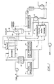
- a possible configuration of the present invention water is sprayed directly into a raw fuel stream (4) immediately prior to entering the evaporative cooler (5).
- the fuel cell As the mist evaporates, the fuel cell is cooled and the fuel stream, which acted as a carrier gas for the mist, is heated.
- the fuel/steam stream is sent through a condenser (6) and a heat exchanger (2) prior to the reformer (7), or it is possible to utilize a steam/liquid separator (as in the prior art; Fig. 2, item 53).
- the waste heat from the reformer (7) can be utilized in the heat exchanger (2) to attain the desired fuel/steam stream temperature prior to the reformer (7), and the necessary fuel stream entrance temperature in the hydro desulfurizer (3).
- the excess steam produced within the evaporative cooler (5) is removed in a condenser (6) to control the fuel/steam ratio in a range from about 2.5 to about 5, and preferably at approximately 3.5.
- the condensate is later used in the contact cooler (12) in order to remove the remaining steam from the exhaust stream for recycling.
- An additional benefit is that by removing the excess steam, the available heat is used more effectively in heating the fuel/steam stream for use within the reformer (7); heating excess steam would be an inefficient utilization of the available heat.
- This technique can be employed with various types of fuel cells, such as Membrane Fuel Cells, Phosphoric Acid Fuel Cells, Alkaline Fuel Cells, Solid Oxide Fuel Cells, and Molten Carbonate Fuel Cells, and various types of fuels, such as methane, propane, naphtha, and natural gas, among others.
- fuel cells such as Membrane Fuel Cells, Phosphoric Acid Fuel Cells, Alkaline Fuel Cells, Solid Oxide Fuel Cells, and Molten Carbonate Fuel Cells
- fuels such as methane, propane, naphtha, and natural gas, among others.
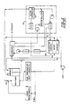
- Fig. 2 a schematic of one prior art cooling scheme, shows a technique of using evaporative cooling to cool a fuel cell.
- liquid water is not sprayed into the fuel stream. Instead, liquid water is passed, in tubes, through the evaporative cooler (50), entering at (51) in the liquid phase and exiting at (52) as a two phase steam/liquid mixture. This mixture is separated in a steam separator (53); the steam is mixed with the fuel stream at point (40). The water, meanwhile, proceeds through a recycle loop.
- the evaporator section in the stack contains fuel and water at the same pressure as the fuel and oxidant, therefore similar materials of construction can be used in the evaporative cooler as in the remainder of the cell parts.
- the system in the present invention is simpler than prior art because the water from the water recovery contact cooler (Fig. 1, item 12) is added directly to the fuel in the evaporative cooler (5).
- prior art Fig. 2
- the water from the water recovery condenser must first be added to the water recycle loop (55).
- the system in the present invention is also better than other evaporative cooling approaches which evaporate the water into the cathode exhaust gas.
- 4,678,723 discloses (incorporated herein by reference) sending the cathode exhaust, with the water vapor added, to the membrane. But the nitrogen in the air dilutes the hydrogen produced in the reformer causing a loss in performance of the cells. This must be compensated by turbocharging the system, complicating the system and adding cost.
- the system according to the invention is simple with configurations less restricting than the prior art.
Landscapes
- Life Sciences & Earth Sciences (AREA)
- Engineering & Computer Science (AREA)
- Manufacturing & Machinery (AREA)
- Sustainable Development (AREA)
- Sustainable Energy (AREA)
- Chemical & Material Sciences (AREA)
- Chemical Kinetics & Catalysis (AREA)
- Electrochemistry (AREA)
- General Chemical & Material Sciences (AREA)
- Fuel Cell (AREA)
- Hydrogen, Water And Hydrids (AREA)
Abstract
Description
- This invention relates to an improved fuel cell system, and especially to using evaporative cooling in combination with the fuel gas for temperature control.
- Fuel cells in which fuel and oxidant react to produce electricity and water are well known in the art. Electricity is generally produced at a catalyst/electrolyte, which usually forms a common wall separating an anode chamber and a cathode chamber. A fuel, such as hydrogen, is introduced to the anode chamber, while an oxidant, such as oxygen or air, is introduced to the cathode chamber. In a Membrane Fuel Cell operating on hydrogen and oxygen, for example, the hydrogen is ionized at a catalyst, forming hydrogen ions and free electrons. The ions pass through the ion exchange membrane and react with oxygen to form water. In a Molten Carbonate Fuel Cell, on the other hand, oxygen reacts with carbon dioxide to form carbonate ions. The ions cross the ion exchange membrane where they react with hydrogen form water, carbon dioxide, and free electrons.
- Although the exact reaction which produces electricity in the various fuel cells; Membrane Fuel Cell, Phosphoric Acid Fuel Cell, Molten Carbonate Fuel Cell, Solid Oxide Fuel Cell, or Alkaline Fuel Cell (hereafter referred to as fuel cell), may differ, all of the overall reactions are exothermic; producing waste heat.
- In order to allow a fuel cell to operate continuously, the waste heat must be removed. Cooling, by altering the phase of a substance, typically water, from the liquid to the gaseous phase by addition of heat, can be employed to accomplish this task.
- Various fuel cell cooling methods have been developed. U.S. Pat. No. 4,344,849 (incorporated herein by reference) discloses a technique which consists of passing water through separate coolant passages within the fuel cell. Some of the water is converted to steam; creating a two phase steam/liquid mixture. The steam and liquid are separated, the steam for use in the reformer and the water for recycle. U.S. Pat. No. 4,795,683 (incorporated herein by reference), discloses a technique of cooling a fuel cell by supplying a controlled amount of liquid water, as mist, to the anode, transporting the water through the ion exchange membrane to the cathode, and evaporating the water.
- An object of the present invention is to provide a more efficient coolant process for use within a fuel cell system.
- The present invention comprises a method of cooling a fuel cell using evaporative cooling. A gaseous fuel stream is sprayed with water, prior to entering an evaporative cooler; an area adjacent to the fuel cell where waste heat from the fuel cell causes the water particles carried in the fuel to evaporate. As the water evaporates it cools the fuel cell. The fuel stream, now a mixture of fuel, such as methane, and steam, can be utilized in the reformer where the fuel and steam react to form processed fuel, a mixture of raw fuel, steam, hydrogen, carbon dioxide, and carbon monoxide. Additional hydrogen, for use as fuel within the fuel cell, is formed in a low temperature shift reactor which reacts the carbon monoxide and steam.
- The foregoing and other features and advantages of the present invention will become more apparent from the following description and accompanying drawings.
-
- Fig. 1 is a schematic of a possible configuration utilizing the present invention.
- Fig. 2 is a schematic of one prior art scheme, including the water recycle.
- As fuel cells generate electricity, they also generate heat. This waste heat must be removed for continuous operation. Various evaporative cooling methods have been employed in the prior art to accomplish this task. However, these methods limit the fuel cell system to certain configurations due, in most instances, to the need to separate the steam from the liquid water, to mix the steam and fuel streams, and to scrub the recycle water. This invention broadens the choices for configurations since it is not necessary to handle the stream/liquid mixture in a separate loop.
- Referring to Fig. 1, a possible configuration of the present invention, water is sprayed directly into a raw fuel stream (4) immediately prior to entering the evaporative cooler (5). As the mist evaporates, the fuel cell is cooled and the fuel stream, which acted as a carrier gas for the mist, is heated. The fuel/steam stream is sent through a condenser (6) and a heat exchanger (2) prior to the reformer (7), or it is possible to utilize a steam/liquid separator (as in the prior art; Fig. 2, item 53). The waste heat from the reformer (7) can be utilized in the heat exchanger (2) to attain the desired fuel/steam stream temperature prior to the reformer (7), and the necessary fuel stream entrance temperature in the hydro desulfurizer (3).
- The excess steam produced within the evaporative cooler (5) is removed in a condenser (6) to control the fuel/steam ratio in a range from about 2.5 to about 5, and preferably at approximately 3.5. The condensate is later used in the contact cooler (12) in order to remove the remaining steam from the exhaust stream for recycling. An additional benefit is that by removing the excess steam, the available heat is used more effectively in heating the fuel/steam stream for use within the reformer (7); heating excess steam would be an inefficient utilization of the available heat.
- This technique can be employed with various types of fuel cells, such as Membrane Fuel Cells, Phosphoric Acid Fuel Cells, Alkaline Fuel Cells, Solid Oxide Fuel Cells, and Molten Carbonate Fuel Cells, and various types of fuels, such as methane, propane, naphtha, and natural gas, among others.
- Fig. 2, a schematic of one prior art cooling scheme, shows a technique of using evaporative cooling to cool a fuel cell. In this schematic, however, liquid water is not sprayed into the fuel stream. Instead, liquid water is passed, in tubes, through the evaporative cooler (50), entering at (51) in the liquid phase and exiting at (52) as a two phase steam/liquid mixture. This mixture is separated in a steam separator (53); the steam is mixed with the fuel stream at point (40). The water, meanwhile, proceeds through a recycle loop. Problems inherent with this system include: impure water which causes debris to accumulate within the tubes and/or of other areas of the water recycle loop (55); the water recycle loop (55) requires more equipment than the present invention; the water recycle loop (55) is at a different pressure than the cell requiring the water tubes in the stack to be expensive material, such as stainless steel.
- In the present invention the evaporator section in the stack contains fuel and water at the same pressure as the fuel and oxidant, therefore similar materials of construction can be used in the evaporative cooler as in the remainder of the cell parts. Furthermore, the system in the present invention is simpler than prior art because the water from the water recovery contact cooler (Fig. 1, item 12) is added directly to the fuel in the evaporative cooler (5). In prior art (Fig. 2) the water from the water recovery condenser must first be added to the water recycle loop (55). The system in the present invention is also better than other evaporative cooling approaches which evaporate the water into the cathode exhaust gas. U.S. Pat. No. 4,678,723 discloses (incorporated herein by reference) sending the cathode exhaust, with the water vapor added, to the membrane. But the nitrogen in the air dilutes the hydrogen produced in the reformer causing a loss in performance of the cells. This must be compensated by turbocharging the system, complicating the system and adding cost. The system according to the invention is simple with configurations less restricting than the prior art.
- Although this invention has been shown and described with respect to detailed embodiments thereof, it will be understood by those skilled in the art that various changes in form and detail thereof may be made without departing from the spirit and scope of the claimed invention.
Claims (12)
a. spraying water into the fuel stream to form mist;
b. introducing the fuel/mist stream to the evaporative cooler; and
c. evaporating the water into the fuel stream using the evaporative cooler;
whereby the fuel acts as a carrier gas for the water particles prior to evaporation.
a. spraying water into the fuel stream to form mist, wherein the fuel acts as a carrier gas;
b. introducing the fuel/mist stream to the evaporative cooler;
c. evaporating the water into the fuel stream using the evaporative cooler;
d. located adjacent to the fuel cell;
whereby the exothermic reaction occurring within the fuel cell produces the heat which causes the water to evaporate; a phase change which absorbs the heat, cooling the fuel cell.
Applications Claiming Priority (2)
| Application Number | Priority Date | Filing Date | Title |
|---|---|---|---|
| US399680 | 1982-07-19 | ||
| US07/399,680 US4994331A (en) | 1989-08-28 | 1989-08-28 | Fuel cell evaporative cooling using fuel as a carrier gas |
Publications (2)
| Publication Number | Publication Date |
|---|---|
| EP0415330A2 true EP0415330A2 (en) | 1991-03-06 |
| EP0415330A3 EP0415330A3 (en) | 1991-07-31 |
Family
ID=23580546
Family Applications (1)
| Application Number | Title | Priority Date | Filing Date |
|---|---|---|---|
| EP19900116403 Ceased EP0415330A3 (en) | 1989-08-28 | 1990-08-27 | Fuel cell evaporative cooling using fuel as a carrier gas |
Country Status (4)
| Country | Link |
|---|---|
| US (1) | US4994331A (en) |
| EP (1) | EP0415330A3 (en) |
| JP (1) | JPH03184269A (en) |
| CA (1) | CA2024066A1 (en) |
Cited By (6)
| Publication number | Priority date | Publication date | Assignee | Title |
|---|---|---|---|---|
| DE19636068C1 (en) * | 1996-09-05 | 1998-05-28 | Siemens Ag | Apparatus for recovery of hydrogen and/or synthesis gas |
| DE19741331A1 (en) * | 1997-09-19 | 1999-04-01 | Forschungszentrum Juelich Gmbh | Method and device for cooling in fuel cells |
| AT407315B (en) * | 1998-11-23 | 2001-02-26 | Vaillant Gmbh | CHP POWER PLANT |
| WO2004055926A2 (en) * | 2002-12-16 | 2004-07-01 | Nuvera Fuel Cells Europe S.R.L. | Pem fuel cell system with cooling and internal humidification |
| CN100453914C (en) * | 2007-06-11 | 2009-01-21 | 梁显庭 | Instant-heating refrigerant hot-water apparatus of inductive evaporation refrigerating |
| DE102014205718A1 (en) * | 2014-03-27 | 2015-10-01 | Robert Bosch Gmbh | fuel cell device |
Families Citing this family (87)
| Publication number | Priority date | Publication date | Assignee | Title |
|---|---|---|---|---|
| JPH0333002A (en) * | 1989-06-29 | 1991-02-13 | Hitachi Ltd | Hydrogen producing device |
| JPH03201370A (en) * | 1989-12-27 | 1991-09-03 | Sekiyu Sangyo Katsuseika Center | Method of improving process of fuel cell power generation |
| US5043232A (en) * | 1990-05-10 | 1991-08-27 | International Fuel Cells Corporation | Fuel Preheating for a fuel processing system of a fuel cell power plant |
| JP2796181B2 (en) * | 1990-07-23 | 1998-09-10 | 三菱電機株式会社 | Fuel cell power generation system |
| US5206094A (en) * | 1990-11-30 | 1993-04-27 | The United States Of America As Represented By The Secretary Of The Air Force | Fuel cell evaporative cooler |
| US5202195A (en) * | 1990-12-14 | 1993-04-13 | International Fuel Cells Corporation | Method of and arrangement for replenishing hydrogen consumed by a fuel cell device |
| US5213912A (en) * | 1991-12-30 | 1993-05-25 | International Fuel Cells Corporation | Molten carbonate fuel cell sulfur scrubber |
| JP3352716B2 (en) * | 1992-03-31 | 2002-12-03 | 株式会社東芝 | Solid polymer electrolyte fuel cell device |
| US5335628A (en) * | 1993-09-03 | 1994-08-09 | Aqua-Chem, Inc. | Integrated boiler/fuel cell system |
| US5464606A (en) * | 1994-05-27 | 1995-11-07 | Ballard Power Systems Inc. | Two-stage water gas shift conversion method |
| JP3203150B2 (en) * | 1995-05-18 | 2001-08-27 | 三洋電機株式会社 | Polymer electrolyte fuel cell and polymer electrolyte fuel cell system |
| US6162556A (en) * | 1995-12-04 | 2000-12-19 | Siemens Aktiengesellschaft | Method for operating a high-temperature fuel cell installation, and a high-temperature fuel cell installation |
| US6126908A (en) * | 1996-08-26 | 2000-10-03 | Arthur D. Little, Inc. | Method and apparatus for converting hydrocarbon fuel into hydrogen gas and carbon dioxide |
| WO1999010945A1 (en) * | 1997-08-26 | 1999-03-04 | Shell Internationale Research Maatschappij B.V. | Producing electrical energy from natural gas using a solid oxide fuel cell |
| US6030718A (en) * | 1997-11-20 | 2000-02-29 | Avista Corporation | Proton exchange membrane fuel cell power system |
| US6232005B1 (en) | 1997-11-20 | 2001-05-15 | General Motors Corporation | Fuel cell system combustor |
| US6096449A (en) * | 1997-11-20 | 2000-08-01 | Avista Labs | Fuel cell and method for controlling same |
| US6387556B1 (en) | 1997-11-20 | 2002-05-14 | Avista Laboratories, Inc. | Fuel cell power systems and methods of controlling a fuel cell power system |
| USRE39556E1 (en) * | 1997-11-20 | 2007-04-10 | Relion, Inc. | Fuel cell and method for controlling same |
| US6077620A (en) * | 1997-11-26 | 2000-06-20 | General Motors Corporation | Fuel cell system with combustor-heated reformer |
| US6045772A (en) * | 1998-08-19 | 2000-04-04 | International Fuel Cells, Llc | Method and apparatus for injecting a liquid hydrocarbon fuel into a fuel cell power plant reformer |
| US6921597B2 (en) | 1998-09-14 | 2005-07-26 | Questair Technologies Inc. | Electrical current generation system |
| US6210821B1 (en) * | 1998-12-28 | 2001-04-03 | International Fuel Cells Co, Llc | System for implementing operation and start-up of a vehicle which is powered by electricity from a fuel cell power plant |
| US6207308B1 (en) * | 1999-04-20 | 2001-03-27 | International Fuel Cells, Llc | Water treatment system for a fuel cell assembly |
| US6641625B1 (en) | 1999-05-03 | 2003-11-04 | Nuvera Fuel Cells, Inc. | Integrated hydrocarbon reforming system and controls |
| US6455180B1 (en) | 1999-07-02 | 2002-09-24 | General Motors Corporation | Flexible method for monitoring fuel cell voltage |
| US6306531B1 (en) | 1999-07-06 | 2001-10-23 | General Motors Corporation | Combustor air flow control method for fuel cell apparatus |
| EP1069636B1 (en) * | 1999-07-06 | 2016-03-23 | GM Global Technology Operations LLC | Fuel cell stack monitoring and system control |
| US6159626A (en) * | 1999-07-06 | 2000-12-12 | General Motors Corporation | Fuel cell system logic for differentiating between rapid and normal shutdown commands |
| US6391484B1 (en) | 1999-07-06 | 2002-05-21 | General Motors Corporation | Fuel processor temperature monitoring and control |
| US6436561B1 (en) | 1999-07-21 | 2002-08-20 | General Motors Corporation | Methanol tailgas combustor control method |
| US6350535B1 (en) | 1999-08-27 | 2002-02-26 | Plug Power Inc. | Mist evaporation system for fuel cell hydration |
| US6316134B1 (en) * | 1999-09-13 | 2001-11-13 | Ballard Generation Systems, Inc. | Fuel cell electric power generation system |
| US6406806B1 (en) | 1999-11-09 | 2002-06-18 | General Motors Corporation | Fuel cell voltage monitoring and system control |
| US6413661B1 (en) | 1999-12-15 | 2002-07-02 | General Motors Corporation | Method for operating a combustor in a fuel cell system |
| US6451465B1 (en) | 2000-02-07 | 2002-09-17 | General Motors Corporation | Method for operating a combustor in a fuel cell system |
| US6395414B1 (en) * | 2000-02-11 | 2002-05-28 | General Motors Corporation | Staged venting of fuel cell system during rapid shutdown |
| US6416893B1 (en) | 2000-02-11 | 2002-07-09 | General Motors Corporation | Method and apparatus for controlling combustor temperature during transient load changes |
| US6376112B1 (en) | 2000-02-11 | 2002-04-23 | General Motors Corporation | Controlled shutdown of a fuel cell |
| US6413662B1 (en) | 2000-02-22 | 2002-07-02 | General Motors Corporation | Fuel cell system shutdown with anode pressure control |
| US6602624B1 (en) | 2000-02-22 | 2003-08-05 | General Motors Corporation | Control apparatus and method for efficiently heating a fuel processor in a fuel cell system |
| US6428918B1 (en) | 2000-04-07 | 2002-08-06 | Avista Laboratories, Inc. | Fuel cell power systems, direct current voltage converters, fuel cell power generation methods, power conditioning methods and direct current power conditioning methods |
| DE10023036A1 (en) * | 2000-05-11 | 2001-11-22 | Siemens Ag | Process for cold starting fuel cells in a fuel cell arrangement comprises directly converting process gas in a catalytic reaction on a suitable catalyst into thermal energy, and using the thermal energy to heat the fuel cell arrangement |
| US6468682B1 (en) | 2000-05-17 | 2002-10-22 | Avista Laboratories, Inc. | Ion exchange membrane fuel cell |
| US7326480B2 (en) * | 2000-05-17 | 2008-02-05 | Relion, Inc. | Fuel cell power system and method of controlling a fuel cell power system |
| US6916564B2 (en) * | 2000-05-31 | 2005-07-12 | Nuvera Fuel Cells, Inc. | High-efficiency fuel cell power system with power generating expander |
| US6921595B2 (en) | 2000-05-31 | 2005-07-26 | Nuvera Fuel Cells, Inc. | Joint-cycle high-efficiency fuel cell system with power generating turbine |
| US6551732B1 (en) | 2000-09-18 | 2003-04-22 | Air Products And Chemicals, Inc. | Use of fuel cell cathode effluent in a fuel reformer to produce hydrogen for the fuel cell anode |
| US6779351B2 (en) * | 2000-09-27 | 2004-08-24 | Idalex Technologies, Inc. | Fuel cell systems with evaporative cooling and methods for humidifying and adjusting the temperature of the reactant streams |
| US6485854B1 (en) * | 2000-10-19 | 2002-11-26 | General Motors Corporation | Gas-liquid separator for fuel cell system |
| JP2004512650A (en) * | 2000-10-27 | 2004-04-22 | クエストエアー テクノロジーズ インコーポレイテッド | System and method for supplying hydrogen to a fuel cell |
| US7097925B2 (en) * | 2000-10-30 | 2006-08-29 | Questair Technologies Inc. | High temperature fuel cell power plant |
| CA2325072A1 (en) * | 2000-10-30 | 2002-04-30 | Questair Technologies Inc. | Gas separation for molten carbonate fuel cell |
| DE10057018A1 (en) * | 2000-11-17 | 2002-05-23 | Xcellsis Gmbh | Gas generating system for a reformer and method for providing a gas stream to be supplied to a reformer |
| CA2356220C (en) * | 2001-03-30 | 2007-06-12 | Ishikawajima-Harima Heavy Industries Co., Ltd. | Method and apparatus for reforming fuel |
| CA2469401A1 (en) | 2001-12-05 | 2003-06-19 | Lawrence G. Clawson | High efficiency otto cycle engine with power generating expander |
| AU2003224627A1 (en) * | 2002-02-22 | 2003-09-09 | Idalex Technologies, Inc. | Fuel cell systems with evaporative cooling and methods for humidifying and adjusting the temperature of the reactant streams |
| US7387849B2 (en) * | 2002-03-14 | 2008-06-17 | Questair Technologies Inc. | Hydrogen recycle for solid oxide fuel cell |
| US6832647B2 (en) | 2002-04-02 | 2004-12-21 | Modine Manufacturing Company | Integrated condenser/separator for fuel cell exhaust gases |
| US7507384B2 (en) * | 2002-06-13 | 2009-03-24 | Nuvera Fuel Cells, Inc. | Preferential oxidation reactor temperature regulation |
| US6852435B2 (en) * | 2002-07-23 | 2005-02-08 | Deere & Company | Fuel cell cooling system |
| US6743410B2 (en) * | 2002-08-02 | 2004-06-01 | General Motors Corporation | Primary reactor liquid water and air injection for improved management of a fuel processor |
| US7285350B2 (en) * | 2002-09-27 | 2007-10-23 | Questair Technologies Inc. | Enhanced solid oxide fuel cell systems |
| US7556874B2 (en) * | 2003-08-27 | 2009-07-07 | Utc Power Corporation | Fuel cell temperature control by evaporative cooling |
| DE10341516A1 (en) * | 2003-08-28 | 2005-03-24 | Volkswagen Ag | Fuel cell system especially for an electric vehicle has air supply to exhaust gas after burner that conducts part of anode exhaust gas to the burner |
| US7452617B2 (en) * | 2003-12-16 | 2008-11-18 | General Motors Corporation | Fuel cell dielectric coolant and evaporative cooling process using same |
| WO2006083296A2 (en) * | 2004-06-11 | 2006-08-10 | Nuvera Fuel Cells, Inc. | Fuel fired hydrogen generator |
| US7189280B2 (en) * | 2004-06-29 | 2007-03-13 | Questair Technologies Inc. | Adsorptive separation of gas streams |
| CA2585963A1 (en) * | 2004-11-05 | 2006-05-18 | Questair Technologies Inc. | Separation of carbon dioxide from other gases |
| US7659022B2 (en) * | 2006-08-14 | 2010-02-09 | Modine Manufacturing Company | Integrated solid oxide fuel cell and fuel processor |
| WO2007087305A2 (en) * | 2006-01-23 | 2007-08-02 | Bloom Energy Corporation | Integrated solid oxide fuel cell and fuel processor |
| US9190693B2 (en) | 2006-01-23 | 2015-11-17 | Bloom Energy Corporation | Modular fuel cell system |
| US8241801B2 (en) | 2006-08-14 | 2012-08-14 | Modine Manufacturing Company | Integrated solid oxide fuel cell and fuel processor |
| US8026020B2 (en) | 2007-05-08 | 2011-09-27 | Relion, Inc. | Proton exchange membrane fuel cell stack and fuel cell stack module |
| US9293778B2 (en) | 2007-06-11 | 2016-03-22 | Emergent Power Inc. | Proton exchange membrane fuel cell |
| US8920997B2 (en) | 2007-07-26 | 2014-12-30 | Bloom Energy Corporation | Hybrid fuel heat exchanger—pre-reformer in SOFC systems |
| US8852820B2 (en) | 2007-08-15 | 2014-10-07 | Bloom Energy Corporation | Fuel cell stack module shell with integrated heat exchanger |
| US8003274B2 (en) * | 2007-10-25 | 2011-08-23 | Relion, Inc. | Direct liquid fuel cell |
| WO2009105191A2 (en) | 2008-02-19 | 2009-08-27 | Bloom Energy Corporation | Fuel cell system containing anode tail gas oxidizer and hybrid heat exchanger/reformer |
| US8968958B2 (en) * | 2008-07-08 | 2015-03-03 | Bloom Energy Corporation | Voltage lead jumper connected fuel cell columns |
| US8440362B2 (en) | 2010-09-24 | 2013-05-14 | Bloom Energy Corporation | Fuel cell mechanical components |
| US8877399B2 (en) | 2011-01-06 | 2014-11-04 | Bloom Energy Corporation | SOFC hot box components |
| US9755263B2 (en) | 2013-03-15 | 2017-09-05 | Bloom Energy Corporation | Fuel cell mechanical components |
| WO2015061274A1 (en) | 2013-10-23 | 2015-04-30 | Bloom Energy Corporation | Pre-reformer for selective reformation of higher hydrocarbons |
| WO2015123304A1 (en) | 2014-02-12 | 2015-08-20 | Bloom Energy Corporation | Structure and method for fuel cell system where multiple fuel cells and power electronics feed loads in parallel allowing for integrated electrochemical impedance spectroscopy ("eis") |
| US10651496B2 (en) | 2015-03-06 | 2020-05-12 | Bloom Energy Corporation | Modular pad for a fuel cell system |
| US11398634B2 (en) | 2018-03-27 | 2022-07-26 | Bloom Energy Corporation | Solid oxide fuel cell system and method of operating the same using peak shaving gas |
Citations (8)
| Publication number | Priority date | Publication date | Assignee | Title |
|---|---|---|---|---|
| DE2044431A1 (en) * | 1969-10-06 | 1971-04-29 | United Aircraft Corp | Fuel more saturated for low temperature fuel cells |
| US3905884A (en) * | 1974-11-20 | 1975-09-16 | United Technologies Corp | Electrolysis cell system including recirculating product gas stream for cooling the cell |
| EP0267137A1 (en) * | 1986-11-03 | 1988-05-11 | International Fuel Cells Corporation | High pressure low heat rate phosphoric acid fuel cell stack |
| US4769297A (en) * | 1987-11-16 | 1988-09-06 | International Fuel Cells Corporation | Solid polymer electrolyte fuel cell stack water management system |
| JPS63232273A (en) * | 1987-03-20 | 1988-09-28 | Hitachi Ltd | Fuel cell cooling device |
| US4795683A (en) * | 1987-07-23 | 1989-01-03 | United Technologies Corporation | High power density evaporatively cooled ion exchange membrane fuel cell |
| EP0316626A1 (en) * | 1987-11-12 | 1989-05-24 | Daimler-Benz Aktiengesellschaft | Electrochemical cell |
| EP0356906A1 (en) * | 1988-08-24 | 1990-03-07 | International Fuel Cells Corporation | Hydrogen fuel reforming in a fog cooled fuel cell power plant assembly |
Family Cites Families (3)
| Publication number | Priority date | Publication date | Assignee | Title |
|---|---|---|---|---|
| US3982962A (en) * | 1975-02-12 | 1976-09-28 | United Technologies Corporation | Pressurized fuel cell power plant with steam powered compressor |
| US4824740A (en) * | 1987-06-15 | 1989-04-25 | International Fuel Cell Corporation | Fuel cell stack cooling system |
| US4781241A (en) * | 1987-08-27 | 1988-11-01 | International Fuel Cells Corporation | Heat exchanger for fuel cell power plant reformer |
-
1989
- 1989-08-28 US US07/399,680 patent/US4994331A/en not_active Expired - Lifetime
-
1990
- 1990-08-27 EP EP19900116403 patent/EP0415330A3/en not_active Ceased
- 1990-08-27 CA CA002024066A patent/CA2024066A1/en not_active Abandoned
- 1990-08-28 JP JP2226403A patent/JPH03184269A/en active Pending
Patent Citations (8)
| Publication number | Priority date | Publication date | Assignee | Title |
|---|---|---|---|---|
| DE2044431A1 (en) * | 1969-10-06 | 1971-04-29 | United Aircraft Corp | Fuel more saturated for low temperature fuel cells |
| US3905884A (en) * | 1974-11-20 | 1975-09-16 | United Technologies Corp | Electrolysis cell system including recirculating product gas stream for cooling the cell |
| EP0267137A1 (en) * | 1986-11-03 | 1988-05-11 | International Fuel Cells Corporation | High pressure low heat rate phosphoric acid fuel cell stack |
| JPS63232273A (en) * | 1987-03-20 | 1988-09-28 | Hitachi Ltd | Fuel cell cooling device |
| US4795683A (en) * | 1987-07-23 | 1989-01-03 | United Technologies Corporation | High power density evaporatively cooled ion exchange membrane fuel cell |
| EP0316626A1 (en) * | 1987-11-12 | 1989-05-24 | Daimler-Benz Aktiengesellschaft | Electrochemical cell |
| US4769297A (en) * | 1987-11-16 | 1988-09-06 | International Fuel Cells Corporation | Solid polymer electrolyte fuel cell stack water management system |
| EP0356906A1 (en) * | 1988-08-24 | 1990-03-07 | International Fuel Cells Corporation | Hydrogen fuel reforming in a fog cooled fuel cell power plant assembly |
Non-Patent Citations (1)
| Title |
|---|
| PATENT ABSTRACTS OF JAPAN, vol. 13, no. 31 (E-707)[3379], 24th January 1989; & JP-A-63 232 273 (HITACHI LTD) 28-09-1988 * |
Cited By (10)
| Publication number | Priority date | Publication date | Assignee | Title |
|---|---|---|---|---|
| DE19636068C1 (en) * | 1996-09-05 | 1998-05-28 | Siemens Ag | Apparatus for recovery of hydrogen and/or synthesis gas |
| DE19636068C2 (en) * | 1996-09-05 | 2002-02-28 | Siemens Ag | Device and method for hydrogen and / or synthesis gas production |
| DE19741331A1 (en) * | 1997-09-19 | 1999-04-01 | Forschungszentrum Juelich Gmbh | Method and device for cooling in fuel cells |
| DE19741331C2 (en) * | 1997-09-19 | 2002-04-04 | Forschungszentrum Juelich Gmbh | Cooling method for fuel cells |
| AT407315B (en) * | 1998-11-23 | 2001-02-26 | Vaillant Gmbh | CHP POWER PLANT |
| WO2004055926A2 (en) * | 2002-12-16 | 2004-07-01 | Nuvera Fuel Cells Europe S.R.L. | Pem fuel cell system with cooling and internal humidification |
| WO2004055926A3 (en) * | 2002-12-16 | 2005-03-17 | Nuvera Fuel Cells Europ Srl | Pem fuel cell system with cooling and internal humidification |
| US7396602B2 (en) | 2002-12-16 | 2008-07-08 | Nuvera Fuel Cells Europe S.R.L. | Electrochemical generator and method for its utilisation |
| CN100453914C (en) * | 2007-06-11 | 2009-01-21 | 梁显庭 | Instant-heating refrigerant hot-water apparatus of inductive evaporation refrigerating |
| DE102014205718A1 (en) * | 2014-03-27 | 2015-10-01 | Robert Bosch Gmbh | fuel cell device |
Also Published As
| Publication number | Publication date |
|---|---|
| JPH03184269A (en) | 1991-08-12 |
| US4994331A (en) | 1991-02-19 |
| EP0415330A3 (en) | 1991-07-31 |
| CA2024066A1 (en) | 1991-03-01 |
Similar Documents
| Publication | Publication Date | Title |
|---|---|---|
| US4994331A (en) | Fuel cell evaporative cooling using fuel as a carrier gas | |
| EP0184970B1 (en) | Process for generating steam in a fuel cell powerplant | |
| EP0356906B1 (en) | Hydrogen fuel reforming in a fog cooled fuel cell power plant assembly | |
| US3615839A (en) | Fuel cell system with recycle stream | |
| EP0376219B1 (en) | Electric power producing system using molten carbonate type fuel cell | |
| US4595642A (en) | Fuel cell composite plant | |
| KR101137207B1 (en) | Integrated high efficiency fossil fuel power plant/fuel cell system with co2 emissions abatement | |
| US4917971A (en) | Internal reforming fuel cell system requiring no recirculated cooling and providing a high fuel process gas utilization | |
| US5380600A (en) | Fuel cell system | |
| US4902586A (en) | Once through molten carbonate fuel cell system | |
| US4751151A (en) | Recovery of carbon dioxide from fuel cell exhaust | |
| US5187024A (en) | Fuel cell generating system | |
| US4080487A (en) | Process for cooling molten carbonate fuel cell stacks and apparatus therefor | |
| EP0184541A2 (en) | Process for humidifying a gaseous fuel stream | |
| KR20010041687A (en) | Process gas purification and fuel cell system | |
| EP0456848A1 (en) | Electric power producing system using molten carbonate type fuel cell | |
| US20130130134A1 (en) | Solid oxide fuel cell steam reforming power system | |
| US6692854B2 (en) | Fuel cell generator system and method for operating same | |
| JPH1126004A (en) | Power generating system | |
| WO2000039875A1 (en) | A hydrocarbon fueled power plant employing a proton exchange membrane (pem) fuel cell | |
| CA1306770C (en) | Process and apparatus for producing nitrogen | |
| EP0521185B1 (en) | Power generation method using molten carbonate fuel cells | |
| US20020152680A1 (en) | Fuel cell power plant | |
| JPH0828233B2 (en) | Power plant using molten carbonate fuel cell | |
| JP2751526B2 (en) | Molten carbonate fuel cell power generator |
Legal Events
| Date | Code | Title | Description |
|---|---|---|---|
| PUAI | Public reference made under article 153(3) epc to a published international application that has entered the european phase |
Free format text: ORIGINAL CODE: 0009012 |
|
| AK | Designated contracting states |
Kind code of ref document: A2 Designated state(s): DE FR GB IT NL SE |
|
| PUAL | Search report despatched |
Free format text: ORIGINAL CODE: 0009013 |
|
| AK | Designated contracting states |
Kind code of ref document: A3 Designated state(s): DE FR GB IT NL SE |
|
| EL | Fr: translation of claims filed | ||
| 17P | Request for examination filed |
Effective date: 19920130 |
|
| 17Q | First examination report despatched |
Effective date: 19930810 |
|
| STAA | Information on the status of an ep patent application or granted ep patent |
Free format text: STATUS: THE APPLICATION HAS BEEN REFUSED |
|
| 18R | Application refused |
Effective date: 19951029 |