EP0413656A1 - Programmable, linear collective control system for a helicopter - Google Patents
Programmable, linear collective control system for a helicopter Download PDFInfo
- Publication number
- EP0413656A1 EP0413656A1 EP90630139A EP90630139A EP0413656A1 EP 0413656 A1 EP0413656 A1 EP 0413656A1 EP 90630139 A EP90630139 A EP 90630139A EP 90630139 A EP90630139 A EP 90630139A EP 0413656 A1 EP0413656 A1 EP 0413656A1
- Authority
- EP
- European Patent Office
- Prior art keywords
- signal
- collective
- stick
- collective control
- force
- Prior art date
- Legal status (The legal status is an assumption and is not a legal conclusion. Google has not performed a legal analysis and makes no representation as to the accuracy of the status listed.)
- Granted
Links
Images


Classifications
-
- B—PERFORMING OPERATIONS; TRANSPORTING
- B64—AIRCRAFT; AVIATION; COSMONAUTICS
- B64C—AEROPLANES; HELICOPTERS
- B64C27/00—Rotorcraft; Rotors peculiar thereto
- B64C27/54—Mechanisms for controlling blade adjustment or movement relative to rotor head, e.g. lag-lead movement
- B64C27/56—Mechanisms for controlling blade adjustment or movement relative to rotor head, e.g. lag-lead movement characterised by the control initiating means, e.g. manually actuated
-
- G—PHYSICS
- G05—CONTROLLING; REGULATING
- G05D—SYSTEMS FOR CONTROLLING OR REGULATING NON-ELECTRIC VARIABLES
- G05D1/00—Control of position, course or altitude of land, water, air, or space vehicles, e.g. automatic pilot
- G05D1/0055—Control of position, course or altitude of land, water, air, or space vehicles, e.g. automatic pilot with safety arrangements
- G05D1/0061—Control of position, course or altitude of land, water, air, or space vehicles, e.g. automatic pilot with safety arrangements for transition from automatic pilot to manual pilot and vice versa
-
- G—PHYSICS
- G05—CONTROLLING; REGULATING
- G05D—SYSTEMS FOR CONTROLLING OR REGULATING NON-ELECTRIC VARIABLES
- G05D1/00—Control of position, course or altitude of land, water, air, or space vehicles, e.g. automatic pilot
- G05D1/04—Control of altitude or depth
- G05D1/06—Rate of change of altitude or depth
- G05D1/0607—Rate of change of altitude or depth specially adapted for aircraft
- G05D1/0653—Rate of change of altitude or depth specially adapted for aircraft during a phase of take-off or landing
- G05D1/0661—Rate of change of altitude or depth specially adapted for aircraft during a phase of take-off or landing specially adapted for take-off
- G05D1/0669—Rate of change of altitude or depth specially adapted for aircraft during a phase of take-off or landing specially adapted for take-off specially adapted for vertical take-off
-
- Y—GENERAL TAGGING OF NEW TECHNOLOGICAL DEVELOPMENTS; GENERAL TAGGING OF CROSS-SECTIONAL TECHNOLOGIES SPANNING OVER SEVERAL SECTIONS OF THE IPC; TECHNICAL SUBJECTS COVERED BY FORMER USPC CROSS-REFERENCE ART COLLECTIONS [XRACs] AND DIGESTS
- Y10—TECHNICAL SUBJECTS COVERED BY FORMER USPC
- Y10T—TECHNICAL SUBJECTS COVERED BY FORMER US CLASSIFICATION
- Y10T74/00—Machine element or mechanism
- Y10T74/20—Control lever and linkage systems
- Y10T74/20012—Multiple controlled elements
- Y10T74/20201—Control moves in two planes
Definitions
- This invention relates to a collective control system for a helicopter and more particularly a programmable collective control system with tactile feedback and with a linear, motorized stick.
- Collective axis tasks such as nap-of-the-earth (NOE) flight operations, create difficulty for pilots when using only a multi-axis control stick, because they cannot accurately perceive the extent of collective (lift) input without diverting attention to the cockpit display.
- NOE nap-of-the-earth
- Prior collective sticks such as disclosed in Wright, are pivotally attached to the floor of the aircraft and provide a control signal indicative of angular displacement.
- the sensitivity of collective control is dependent on the length of the stick. Subsequently, prior systems had long collective control sticks requiring significant pilot motion to control the aircraft which added to pilot fatigue.
- the Wright et al provides rotor collective pitch tactile feedback to the pilot because the collective stick "tracks" the multi-axis stick.
- the Wright et al stick does not, however, provide the pilot with tactile feedback as to the rotor load requirement for collective stick commands.
- the pilot is not provided with feedback as to the amount of stress he is putting on the rotor due to the command he is giving through the collective stick.
- a pilot can move the stick its full length of travel very quickly, causing the helicopter to stall momentarily due to the sudden demand for a large change in energy state.
- a stall is discomforting to the pilot and is particularly undesirable if he is reacting to an emergency situation which demands short time response, such as discovery that an adversary is about to fire a weapon at him.
- U.S. Patent No. 4,545,322 (Yang 1985) describes a mechanical device for artificially creating drag on a control stick.
- U.S. Patent No. 4,477,043 (Repperger 1984) discloses a mechanical damping system which is controlled by using a motor or actuator to adjust spring tension.
- U.S. Patent No. 4,236,685 (Kissel 1980) discloses an aircraft steering mechanism with active force feedback. Kissel describes using discreet components to read various dynamic inputs from aircraft flight conditions, interpret those inputs and increase the tension on the flight control stick using a "pitch feel" unit.
- An object of the present invention is to provide an improved collective control system for a helicopter which provides tactile feedback as to collective pitch.
- Another object is to provide a collective control system which is programmable for different pilot requirements and flight profiles.
- Yet another object of the invention is to provide a collective control system which provides damping to prevent pilot induced oscillations.
- a further object of the present invention is to provide an improved motorized collective control stick for a helicopter which is easily programmable, thereby eliminating the need for traditional stick clutch/damper/spring arrangements.
- a programmable, motorized, collective control stick system is used in tandem with a multi-axis control stick system for controlling the collective pitch of a helicopter rotor.
- the collective control stick has a force output (proportional to the amount of force placed on the stick) and a displacement output (proportional to the position of the stick).
- a collective system signal processor reads the collective control stick output signals, the force output of the multi-axis control stick, flight data from a flight system control computer, and various other data, and provides a drive signal for the drive motor of the collective control stick.
- the stick is moved by the motor at a rate controlled by the computer so as not to exceed the limitations of the helicopter.
- the displacement output of the collective control stick is used to drive electro-hydraulic actuators which control the collective pitch of the rotor.
- a sliding stick is mounted on a bearing block which rides on dual shafts contained in a collective control box.
- the bearing block is attached to a belt driven by pulleys and a motor.
- the motor is controlled by a signal processor which provides a motor drive signal indicative of the pilot's desire to change rotor collective pitch.
- the invention provides for simple adjustment to change the "feel" of the collective stick for different pilots' requirements. This may be done using hardware (potentiometers, etc.), software (pilot profile disk, etc.) or through the flight control computer.
- the invention has a small operational range which helps prevent pilot fatigue. It eliminates a clutching mechanism and provides positive drive of the collective stick without slippage. It is lighter, simpler in operation and has less parts to wear out than prior systems.
- the invention has a smaller length of travel and better accuracy than previous systems, allowing the stick to travel its operative length in one second or less.
- the invention allows the damping of the collective stick to be dynamically adjusted as a function of stick rate, position limits, rotor load, environmental conditions, mission profile, vertical acceleration, pitch rate and many other inputs.
- the invention helps prevent pilot induced oscillations, it ensures the engine operates within its acceleration curve and it improves aircraft efficiency.
- the invention can be current limited to provide motor circuit protection.
- a motorized, sliding, collective control stick 2 has a grip 3, which is mounted on a collective control box 4, as is described with respect to Figs. 3-5 hereinafter.
- the position of the collective control stick along its axis is converted to an electrical signal by a linear variable differential transformer 6, (LVDT, shown in greater detail in Figs. 3-5 hereinafter), which is connected by a line 8 to a signal processor 10.
- the position signal (COLLPOS) on line 8 is also connected to a controller circuit 12 for an electrohydraulic actuator 14 which controls a primary actuator 16 that positions a swashplate assembly 18 to determine the collective pitch of the helicopter rotor blades 20.
- the force applied by the pilot to the grip 3 is converted to an electrical signal (COLLFORCE) by a force transducer 22, such as a strain gauge, and connected by a line 24 to the signal processor 10. Also, the output of a select switch 26, placed on the grip 3, is connected by a line 28 to the signal processor 10.
- a force transducer 22 such as a strain gauge
- a multi-axis control stick 30, such as described in Diamond et al, provides a collective force output signal on a line 32 which is utilized by a flight control computer system 34 to provide an appropriate multi-axis stick collective control signal (MULTISTK) that is connected by a line 36 to the signal processor 10.
- the flight control computer system 34 also exchanges data with the signal processor 10 on a data bus 40.
- the signal processor 10 utilizes the inputs on lines 8, 24, 28, 36, 40 and provides a motor command (MOTOR CMD) signal to a motor driver circuit 42 on a line 44.
- the motor driver circuit 42 provides a drive signal on lines 46 to a collective stick motor 48.
- the collective stick motor 48 positions the grip 3 using a pulley arrangement (shown in greater detail in Figs. 3-5 hereinafter).
- Mechanical limit switches 52 located on the collective control box 4, disconnect the motor drive signal 46 from the motor driver circuit 42 if the grip 3 reaches its travel limits.
- the signal processor performs a number of calculations in order to provide the motor command signal. (These calculations are described in Fig. 2A-B hereinafter.) Variables in these calculations provide flexibility in the operation of the collective stick. For example, the gain of the signal processor provides the sensitivity or "feel" of the stick. Higher gain makes the stick more sensitive to pilot commands so that small applied forces result in large rotor collective pitch changes while lower gain has the opposite effect.
- the variables may be provided through adjustments to potentiometers 56 in external circuitry which provide signals on lines 58.
- a motor command calculation routine is stored in the memory of a digital signal processor and reached through entry point 60.
- a LOAD PARAMETER subroutine 62 loads collective control system variable parameters into memory for use during forthcoming calculations.
- the variable PARAMETERS are provided from a number of sources such as the analog signals on lines 58 of Fig. 1, or digital signals provided by the flight control computer system 34 on data bus 40.
- PARAMETERS include variables which are provided for each pilot's specific requirements for collective system responsiveness (e.g., the "feel" of the stick may be programmed this way) and also variables which are used to adjust for dynamic flight conditions.
- the LOAD PARAMETERS subroutine 62 is not shown in detail herein, but may be one of many subroutines known in the art which poles input devices and stores the output data from each device in memory for retrieval during forthcoming calculations.
- a step 64 defines a FORCE parameter as the COLLFORCE signal provided by line 28 of Fig. 1 times a gain K1. This step provides the "feel" of the collective control stick because different values of K1 provide a different responsiveness of the stick.
- a subroutine 66 defines a COLLRATE parameter as a gain K2 times the differential of the COLLPOS parameter provided on line 8 of Fig. 1.
- the COLLRATE subroutine is not shown in detail herein but may be any one of a number of programs known in the art to differentiate a parameter with respect to time.
- Test 68 determines whether or not FORCE is being provided. If so, a test 70 determines its direction.
- FORCE is redefined by subtracting a forward deadband (FWDDBND) from FORCE and multiplying this value by a forward gain parameter (FWDGAIN) in a subroutine 72.
- FWDDBND forward deadband
- FWDGAIN forward gain parameter
- a subroutine 74 redefines FORCE as FORCE minus an aft deadband (AFTDBAND) multiplied by an aft gain value (AFTGAIN).
- FWDDBND and AFTDBND create a deadband which prevents helicopter vibrations and noise from causing extraneous motor command signals.
- FWDGAIN and AFTGAIN are parameters which allow the feel of the collective stick 2 to be different for forward and aft movement.
- Test 76 determines if FORCE is greater than the deadband (manifested by the fact that FORCE will be a negative number at this point if FORCE is less than AFTDBND or FWDDBND). If it isn't, step 78 sets FORCE equal to zero to eliminate any motor command. If FORCE is greater than the deadband, test 80 determines if the pilot has engaged the select switch 26 on the grip 3.
- a negative result of test 80 indicates the pilot has not engaged the select switch on the grip and the force applied to the grip will be faded in/out over time as described in steps 82-104 hereinafter.
- An affirmative result to test 80 indicates the pilot has engaged the select switch and therefore does not wish the force to be faded in/out but rather any input he gives to the collective stick will be used immediately for collective control. In essence, engaging the select switch makes the collective stick more "touchy" because the control does not undergo the fade in/out function.
- the select switch is used by the pilot under circumstances in which he wants instantaneous response from his commands through the collective stick.
- Test 82 determines if FORCE is greater than HOLDFORCE. If it is, test 84 determines if a collective flag (indicating the breakout level was previously exceeded) has been set. A negative result of test 84 leads to test 86 to determine if FORCE has exceeded the breakout level. If it has, the collective flag is set in step 88 and a step 90 increments a FADE parameter (originally initialized to zero) by an incremental value A. Test 92 then determines if FADE is greater than a maximum value, and if so, step 96 sets FADE equal to the maximum value. In either case step 94 redefines FORCE as FORCE times FADE.
- the fade in/out routine (steps 82-94) increases FORCE as a function of incremental value A until FADE is the maximum value as set in step 96.
- the collective stick remains engaged as the collective pitch controller until the pilot relieves the pressure he is applying to the grip below HOLDFORCE as determined in test 82.
- step 98 redefines FADE as FADE minus an incremental value B.
- Test 100 determines if FADE is less than zero. If not, FORCE is redefined as FORCE times the new FADE value in step 94. FORCE continues to be faded out as a function of B until test 100 determines that FADE has been decremented below zero.
- Step 102 redefines FADE as zero
- step 104 clears the collective flag and the routine is exited with FORCE having been faded out to zero.
- test 106 determines if either the select switch has been engaged (yes answer to test 80) or the collective flag has been set in step 88.
- An affirmative result means the pilot has selected the collective stick to control rotor collective pitch and FORCE is redefined as FORCE minus the COLLRATE parameter determined in step 66. It has been found the collective stick has a tendency to "run away" from the pilot as he applies force to the grip. The subtraction performed in step 110 prevents this from happening.
- Step 112 defines a damping multiplier parameter W which has a value that varies between zero and one.
- Step 114 then redefines FORCE as FORCE times W. W is dependent on COLLRATE and a DAMP parameter.
- DAMP is not explicitly defined herein, but it may be programmed to be dependent on any number of factors including specific dynamic flight conditions (e.g. rotor loading), mission profile, and pilot preference. These factors are manifested as parameters stored in memory and may be provided by the flight control computer 34. For example, it is undesirable to get lift from the helicopter rotor during a pure rotational manuever.
- the attitude of the helicopter might be measured by a gyro type transducer and read by the flight control computer 34 which would provide the signal processor 10 with a scaled value (on data bus 40) of the amount of rotation the helicopter is undergoing.
- the signal processor would incorporate that value in its computation of DAMP. As DAMP becomes a larger value, W becomes smaller in step 112. FORCE is then reduced in step 114 and the collective control stick becomes harder, if not impossible to move. It is evident that a variety of parameters can be utilized to dampen the collective control stick in this manner.
- step 108 redefines FORCE as an error signal equal to the collective control signal (MULTISTK, line 36 Fig. 2) provided by the multi-axis stick 30 minus the collective stick position signal (COLLPOS).
- Test 116 determines if FORCE is equal to zero. If so, the routine jumps to step 144. If not, test 118 determines the direction of FORCE. If the pilot is pushing the collective stick forward, test 120 determines whether the collective stick position signal (COLLPOS) exceeds limit HILMT. If test 118 determines the pilot is pulling the collective stick in the aft direction, test 122 determines whether COLLPOS exceeds limit LOLMT. If the collective stick is beyond its limits in either test 120 or 122, step 124 redefines FORCE as zero. Steps 118-124 therefore establish a position limit routine whereby if the forward or aft position limits are exceeded, the pilot is able to command the stick in the opposite direction of the limit that has been exceeded.
- Steps 126-142 described hereinafter provide a means for keeping the collective stick motor current draw to within safe operating limits.
- the motor current signal MOTORCURR provided on line 54 of Fig. 1 is compared with a current limit parameter CURRLMT in test 126. If MOTORCURR exceeds CURRLMT, a FORCELMT parameter (originally initialized to MAXFORCE) is decremented by a value in step 128.
- Test 130 determines if FORCELMT is negative. If FORCELMT is negative, step 132 sets it equal to 0. If not, test 134 determines if FORCE is greater than FORCELMT. If test 134 is affirmative, FORCE is set equal to FORCELMT in step 136.
- FORCE was not greater than FORCELMT in test 134, it remains unchanged. Therefore, if the collective stick drive motor is pulling too much current, the motor command signal (manifested as FORCE in the program) is faded out as a function of D until the problem no longer exists.
- step 138 increments FORCELMT by value C.
- step 140 determines if FORCELMT is greater than MAXFORCE.
- MAXFORCE is the maximum value of motor drive command (FORCE) which will keep the motor current draw (MOTORCURR) below the safe operating level (CURRLMT). If FORCELMT is greater than MAXFORCE, step 142 sets FORCELMT equal to MAXFORCE. If not, FORCELMT remains unchanged and test 134 compares FORCE with FORCELMT. Therefore, steps 138-142 fade FORCE in as a function of C once it is determined the motor is no longer drawing too much current.
- Step 144 defines MOTOR CMD (provided on line 44 of Fig. 1) as equal to FORCE and the motor command routine is exited at point 146.
- a grip 3 is mounted on a bearing block 150 having two bores lined with bearings which receive and ride on a pair of dual shafts 152 that are mounted on brackets 154 and attached to the collective control box 4.
- the bearing block 150 is driven along the shafts 152 by a toothed drive belt 156 which is attached to the bearing block with a bracket 158 and bolts 160.
- Drive belt 156 rides on three toothed pulleys 162-166.
- Motor 48 drives pulley 166 with a belt pulley arrangement as shown in Fig. 2 and described hereinafter.
- the motor 48 receives command signals on input leads 168.
- Pulleys 162-166 have toothed hubs 170, that engage with a drive belt 172.
- the core of LVDT 6 is attached to a rod 174 which is secured to the belt 172 by clamp 176 and nut 178.
- the LVDT 6 is mounted to control box 4 by a bracket 180.
- a toothed pulley 182 is secured to the shaft of drive motor 48 and drives a toothed pulley 184 using a belt 186.
- Pulley 184 is connectably attached to pulley 166 via a shaft (not visible) which is disposed within a barrel 188.
- the motor and pulleys described hereinbefore are mounted on brackets 190, 192 which are in turn mounted to control box 4.
- motor 48 is shown connected to pulley 182 which drives belt 186 to turn pulley 184 that is connected to pulley 166 which drives belt 156 around pulley 162.
- the linear differential transformer 6 is mounted on bracket 180. Brackets 190, 192 hold all of the above in place in control box 4.
Abstract
Description
- This invention relates to a collective control system for a helicopter and more particularly a programmable collective control system with tactile feedback and with a linear, motorized stick.
- Traditional helicopter flight control systems utilized a cyclic stick for pitch and roll, pedals for yaw and a collective stick for lift. Commonly owned U.S. Patent No. 4,420,808 (Diamond et al, 1983) discloses a single, multi-axis sidearm control stick that provides control signals in each of the pitch, roll, yaw and collective/lift axes and therefore allows a helicopter to be flows using only one hand. The multi-axis stick detects the amount of force applied in different axes by the pilot and provides signals which are a function of those forces. The stick has limited displacement, which is necessary to eliminate coupling between axes due to hand motion.
- Collective axis tasks, such as nap-of-the-earth (NOE) flight operations, create difficulty for pilots when using only a multi-axis control stick, because they cannot accurately perceive the extent of collective (lift) input without diverting attention to the cockpit display.
- Commonly owned U.S. Pat. No. 4,696,445 (Wright et al, 1987) discloses a displacement-type collective control stick used in conjunction with a force-type multi-axis sidearm control stick to solve this problem. In Wright et al, the collective stick "tracks" the multi-axis stick using a motor/clutch/damper/spring arrangement so that a pilot determines the collective pitch of the rotor by the position of the collective stick and can change rotor pitch using either the multi-axis stick or the collective stick. The signal from the multi-axis stick controls rotor collective pitch until the pilot engages the collective stick. The pilot engages the collective stick in two ways: pushing the stick against it's trim position or pressing a trim release switch on the stick. A clutch mechanism subsequently disengages the stick drive motor and allows the pilot to move the stick, the displacement of which is then used as the collective pitch command signal.
- Prior collective sticks, such as disclosed in Wright, are pivotally attached to the floor of the aircraft and provide a control signal indicative of angular displacement. The sensitivity of collective control is dependent on the length of the stick. Subsequently, prior systems had long collective control sticks requiring significant pilot motion to control the aircraft which added to pilot fatigue.
- Wright et al provides rotor collective pitch tactile feedback to the pilot because the collective stick "tracks" the multi-axis stick. The Wright et al stick does not, however, provide the pilot with tactile feedback as to the rotor load requirement for collective stick commands. In other words, the pilot is not provided with feedback as to the amount of stress he is putting on the rotor due to the command he is giving through the collective stick. For example, a pilot can move the stick its full length of travel very quickly, causing the helicopter to stall momentarily due to the sudden demand for a large change in energy state. A stall is discomforting to the pilot and is particularly undesirable if he is reacting to an emergency situation which demands short time response, such as discovery that an adversary is about to fire a weapon at him.
- Damping systems are disclosed in the prior art for helping to prevent pilot errors as described above. For instance, U.S. Patent No. 4,545,322 (Yang 1985) describes a mechanical device for artificially creating drag on a control stick. U.S. Patent No. 4,477,043 (Repperger 1984) discloses a mechanical damping system which is controlled by using a motor or actuator to adjust spring tension. U.S. Patent No. 4,236,685 (Kissel 1980) discloses an aircraft steering mechanism with active force feedback. Kissel describes using discreet components to read various dynamic inputs from aircraft flight conditions, interpret those inputs and increase the tension on the flight control stick using a "pitch feel" unit.
- It has also been discovered that every pilot desires a different resistance or "feel" in the collective stick movement. Some pilots like to have a "touchy" stick while others prefer the stick to be more difficult to move. The prior mentioned control stick systems have required laborious adjustments to tailor their "feel" to pilot demands while minimizing pilot fatigue.
- An object of the present invention is to provide an improved collective control system for a helicopter which provides tactile feedback as to collective pitch.
- Another object is to provide a collective control system which is programmable for different pilot requirements and flight profiles.
- Yet another object of the invention is to provide a collective control system which provides damping to prevent pilot induced oscillations.
- A further object of the present invention is to provide an improved motorized collective control stick for a helicopter which is easily programmable, thereby eliminating the need for traditional stick clutch/damper/spring arrangements.
- According to the present invention, a programmable, motorized, collective control stick system is used in tandem with a multi-axis control stick system for controlling the collective pitch of a helicopter rotor. The collective control stick has a force output (proportional to the amount of force placed on the stick) and a displacement output (proportional to the position of the stick). A collective system signal processor reads the collective control stick output signals, the force output of the multi-axis control stick, flight data from a flight system control computer, and various other data, and provides a drive signal for the drive motor of the collective control stick. The stick is moved by the motor at a rate controlled by the computer so as not to exceed the limitations of the helicopter. The displacement output of the collective control stick is used to drive electro-hydraulic actuators which control the collective pitch of the rotor.
- According further to the present invention, a sliding stick is mounted on a bearing block which rides on dual shafts contained in a collective control box. The bearing block is attached to a belt driven by pulleys and a motor. The motor is controlled by a signal processor which provides a motor drive signal indicative of the pilot's desire to change rotor collective pitch.
- The invention provides for simple adjustment to change the "feel" of the collective stick for different pilots' requirements. This may be done using hardware (potentiometers, etc.), software (pilot profile disk, etc.) or through the flight control computer.
- The invention has a small operational range which helps prevent pilot fatigue. It eliminates a clutching mechanism and provides positive drive of the collective stick without slippage. It is lighter, simpler in operation and has less parts to wear out than prior systems.
- The invention has a smaller length of travel and better accuracy than previous systems, allowing the stick to travel its operative length in one second or less.
- The invention allows the damping of the collective stick to be dynamically adjusted as a function of stick rate, position limits, rotor load, environmental conditions, mission profile, vertical acceleration, pitch rate and many other inputs. As a result, the invention helps prevent pilot induced oscillations, it ensures the engine operates within its acceleration curve and it improves aircraft efficiency. Also, the invention can be current limited to provide motor circuit protection.
- These and other objects, features and advantages of the present invention will become more apparent in the light of the detailed description of exemplary embodiments thereof as illustrated in the drawing.
-
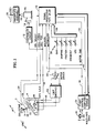
- Fig. 1 is a simplified schematic block diagram of a programmable collective control system in accordance with the present invention.
- Figs. 2A,2B are a logic flowchart illustrative of a program stored in memory for providing the signal processing in the embodiment of Fig. 1.
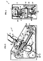
- Fig. 3 is a side view partly broken away and partly in section of a motorized collective control stick in accordance with the present invention.
- Fig. 4 is a sectional view taken along line 2-2 in Fig. 1.
- Fig. 5 is a perspective view partly broken away and partly in section in accordance with the present invention.
- Referring now to Fig. 1, a motorized, sliding,
collective control stick 2 has agrip 3, which is mounted on acollective control box 4, as is described with respect to Figs. 3-5 hereinafter. The position of the collective control stick along its axis is converted to an electrical signal by a linear variabledifferential transformer 6, (LVDT, shown in greater detail in Figs. 3-5 hereinafter), which is connected by aline 8 to asignal processor 10. The position signal (COLLPOS) online 8 is also connected to acontroller circuit 12 for anelectrohydraulic actuator 14 which controls aprimary actuator 16 that positions aswashplate assembly 18 to determine the collective pitch of thehelicopter rotor blades 20. The force applied by the pilot to thegrip 3 is converted to an electrical signal (COLLFORCE) by aforce transducer 22, such as a strain gauge, and connected by aline 24 to thesignal processor 10. Also, the output of aselect switch 26, placed on thegrip 3, is connected by aline 28 to thesignal processor 10. - A
multi-axis control stick 30, such as described in Diamond et al, provides a collective force output signal on aline 32 which is utilized by a flightcontrol computer system 34 to provide an appropriate multi-axis stick collective control signal (MULTISTK) that is connected by aline 36 to thesignal processor 10. The flightcontrol computer system 34 also exchanges data with thesignal processor 10 on adata bus 40. - The
signal processor 10 utilizes the inputs onlines motor driver circuit 42 on aline 44. Themotor driver circuit 42 provides a drive signal on lines 46 to acollective stick motor 48. Thecollective stick motor 48 positions thegrip 3 using a pulley arrangement (shown in greater detail in Figs. 3-5 hereinafter). Mechanical limit switches 52, located on thecollective control box 4, disconnect the motor drive signal 46 from themotor driver circuit 42 if thegrip 3 reaches its travel limits. - The signal processor performs a number of calculations in order to provide the motor command signal. (These calculations are described in Fig. 2A-B hereinafter.) Variables in these calculations provide flexibility in the operation of the collective stick. For example, the gain of the signal processor provides the sensitivity or "feel" of the stick. Higher gain makes the stick more sensitive to pilot commands so that small applied forces result in large rotor collective pitch changes while lower gain has the opposite effect. The variables may be provided through adjustments to
potentiometers 56 in external circuitry which provide signals onlines 58. - Referring now to Fig. 2A, a motor command calculation routine is stored in the memory of a digital signal processor and reached through
entry point 60. ALOAD PARAMETER subroutine 62 loads collective control system variable parameters into memory for use during forthcoming calculations. The variable PARAMETERS are provided from a number of sources such as the analog signals onlines 58 of Fig. 1, or digital signals provided by the flightcontrol computer system 34 ondata bus 40. PARAMETERS include variables which are provided for each pilot's specific requirements for collective system responsiveness (e.g., the "feel" of the stick may be programmed this way) and also variables which are used to adjust for dynamic flight conditions. The LOAD PARAMETERS subroutine 62 is not shown in detail herein, but may be one of many subroutines known in the art which poles input devices and stores the output data from each device in memory for retrieval during forthcoming calculations. - A
step 64 defines a FORCE parameter as the COLLFORCE signal provided byline 28 of Fig. 1 times a gain K1. This step provides the "feel" of the collective control stick because different values of K1 provide a different responsiveness of the stick. Next, asubroutine 66 defines a COLLRATE parameter as a gain K2 times the differential of the COLLPOS parameter provided online 8 of Fig. 1. The COLLRATE subroutine is not shown in detail herein but may be any one of a number of programs known in the art to differentiate a parameter with respect to time.Test 68 determines whether or not FORCE is being provided. If so, atest 70 determines its direction. If FORCE is in the forward direction, (FWD), then FORCE is redefined by subtracting a forward deadband (FWDDBND) from FORCE and multiplying this value by a forward gain parameter (FWDGAIN) in asubroutine 72. If the direction of FORCE is aft (AFT), then asubroutine 74 redefines FORCE as FORCE minus an aft deadband (AFTDBAND) multiplied by an aft gain value (AFTGAIN). FWDDBND and AFTDBND create a deadband which prevents helicopter vibrations and noise from causing extraneous motor command signals. FWDGAIN and AFTGAIN are parameters which allow the feel of thecollective stick 2 to be different for forward and aft movement.Test 76 determines if FORCE is greater than the deadband (manifested by the fact that FORCE will be a negative number at this point if FORCE is less than AFTDBND or FWDDBND). If it isn't, step 78 sets FORCE equal to zero to eliminate any motor command. If FORCE is greater than the deadband,test 80 determines if the pilot has engaged theselect switch 26 on thegrip 3. - A negative result of
test 80 indicates the pilot has not engaged the select switch on the grip and the force applied to the grip will be faded in/out over time as described in steps 82-104 hereinafter. An affirmative result to test 80 indicates the pilot has engaged the select switch and therefore does not wish the force to be faded in/out but rather any input he gives to the collective stick will be used immediately for collective control. In essence, engaging the select switch makes the collective stick more "touchy" because the control does not undergo the fade in/out function. The select switch is used by the pilot under circumstances in which he wants instantaneous response from his commands through the collective stick. - If the pilot wishes to use the collective stick without engaging the select switch he must apply enough force to the grip to first overcome a breakout level (BREAKOUT) and then maintain that force above a threshold value (HOLDFORCE).
Test 82 determines if FORCE is greater than HOLDFORCE. If it is,test 84 determines if a collective flag (indicating the breakout level was previously exceeded) has been set. A negative result oftest 84 leads to test 86 to determine if FORCE has exceeded the breakout level. If it has, the collective flag is set instep 88 and astep 90 increments a FADE parameter (originally initialized to zero) by an incrementalvalue A. Test 92 then determines if FADE is greater than a maximum value, and if so, step 96 sets FADE equal to the maximum value. In eithercase step 94 redefines FORCE as FORCE times FADE. - If the pilot continues to apply force to the collective stick greater than BREAKOUT, the fade in/out routine (steps 82-94) increases FORCE as a function of incremental value A until FADE is the maximum value as set in
step 96. The collective stick remains engaged as the collective pitch controller until the pilot relieves the pressure he is applying to the grip below HOLDFORCE as determined intest 82. If FORCE is below HOLDFORCE,step 98 redefines FADE as FADE minus an incrementalvalue B. Test 100 then determines if FADE is less than zero. If not, FORCE is redefined as FORCE times the new FADE value instep 94. FORCE continues to be faded out as a function of B untiltest 100 determines that FADE has been decremented below zero. Step 102 then redefines FADE as zero,step 104 clears the collective flag and the routine is exited with FORCE having been faded out to zero. - Referring now to Fig. 2B,
test 106 determines if either the select switch has been engaged (yes answer to test 80) or the collective flag has been set instep 88. An affirmative result means the pilot has selected the collective stick to control rotor collective pitch and FORCE is redefined as FORCE minus the COLLRATE parameter determined instep 66. It has been found the collective stick has a tendency to "run away" from the pilot as he applies force to the grip. The subtraction performed instep 110 prevents this from happening. - Step 112 defines a damping multiplier parameter W which has a value that varies between zero and one. Step 114 then redefines FORCE as FORCE times W. W is dependent on COLLRATE and a DAMP parameter. The derivation of DAMP is not explicitly defined herein, but it may be programmed to be dependent on any number of factors including specific dynamic flight conditions (e.g. rotor loading), mission profile, and pilot preference. These factors are manifested as parameters stored in memory and may be provided by the
flight control computer 34. For example, it is undesirable to get lift from the helicopter rotor during a pure rotational manuever. To prevent the pilot from giving a collective lift command through thecollective control stick 2, the attitude of the helicopter might be measured by a gyro type transducer and read by theflight control computer 34 which would provide thesignal processor 10 with a scaled value (on data bus 40) of the amount of rotation the helicopter is undergoing. The signal processor would incorporate that value in its computation of DAMP. As DAMP becomes a larger value, W becomes smaller instep 112. FORCE is then reduced instep 114 and the collective control stick becomes harder, if not impossible to move. It is evident that a variety of parameters can be utilized to dampen the collective control stick in this manner. - If
test 106 has determined the pilot has not engaged the collective stick,step 108 redefines FORCE as an error signal equal to the collective control signal (MULTISTK,line 36 Fig. 2) provided by themulti-axis stick 30 minus the collective stick position signal (COLLPOS). -
Test 116 determines if FORCE is equal to zero. If so, the routine jumps to step 144. If not, test 118 determines the direction of FORCE. If the pilot is pushing the collective stick forward, test 120 determines whether the collective stick position signal (COLLPOS) exceeds limit HILMT. Iftest 118 determines the pilot is pulling the collective stick in the aft direction,test 122 determines whether COLLPOS exceeds limit LOLMT. If the collective stick is beyond its limits in eithertest step 124 redefines FORCE as zero. Steps 118-124 therefore establish a position limit routine whereby if the forward or aft position limits are exceeded, the pilot is able to command the stick in the opposite direction of the limit that has been exceeded. - Steps 126-142 described hereinafter provide a means for keeping the collective stick motor current draw to within safe operating limits. The motor current signal MOTORCURR provided on
line 54 of Fig. 1 is compared with a current limit parameter CURRLMT intest 126. If MOTORCURR exceeds CURRLMT, a FORCELMT parameter (originally initialized to MAXFORCE) is decremented by a value instep 128.Test 130 determines if FORCELMT is negative. If FORCELMT is negative,step 132 sets it equal to 0. If not, test 134 determines if FORCE is greater than FORCELMT. Iftest 134 is affirmative, FORCE is set equal to FORCELMT instep 136. If FORCE was not greater than FORCELMT intest 134, it remains unchanged. Therefore, if the collective stick drive motor is pulling too much current, the motor command signal (manifested as FORCE in the program) is faded out as a function of D until the problem no longer exists. - If
step 126 subsequently determines MOTORCURR is below CURRLMT, step 138 increments FORCELMT byvalue C. Step 140 then determines if FORCELMT is greater than MAXFORCE. MAXFORCE is the maximum value of motor drive command (FORCE) which will keep the motor current draw (MOTORCURR) below the safe operating level (CURRLMT). If FORCELMT is greater than MAXFORCE, step 142 sets FORCELMT equal to MAXFORCE. If not, FORCELMT remains unchanged andtest 134 compares FORCE with FORCELMT. Therefore, steps 138-142 fade FORCE in as a function of C once it is determined the motor is no longer drawing too much current. - Step 144 defines MOTOR CMD (provided on
line 44 of Fig. 1) as equal to FORCE and the motor command routine is exited atpoint 146. - Although shown in terms of a software flowchart, the invention may also be implemented with dedicated digital or analog hardware. In fact, the invention has only been implemented as software algorithms such as those disclosed in U.S. Patents 4,270,168 and 4,564,908, which are hereby incorporated herein by reference. The equivalence between analog, dedicated digital and software is illustrated (in a different context) in U.S. Patent 4,294,162.
- Referring now to Fig. 3 a
grip 3 is mounted on a bearing block 150 having two bores lined with bearings which receive and ride on a pair ofdual shafts 152 that are mounted onbrackets 154 and attached to thecollective control box 4. The bearing block 150 is driven along theshafts 152 by atoothed drive belt 156 which is attached to the bearing block with a bracket 158 and bolts 160.Drive belt 156 rides on three toothed pulleys 162-166.Motor 48 drivespulley 166 with a belt pulley arrangement as shown in Fig. 2 and described hereinafter. Themotor 48 receives command signals on input leads 168. Pulleys 162-166 have toothedhubs 170, that engage with adrive belt 172. The core ofLVDT 6 is attached to arod 174 which is secured to thebelt 172 byclamp 176 and nut 178. TheLVDT 6 is mounted to controlbox 4 by abracket 180. - Referring now to Fig. 4 a
toothed pulley 182 is secured to the shaft ofdrive motor 48 and drives atoothed pulley 184 using abelt 186.Pulley 184 is connectably attached topulley 166 via a shaft (not visible) which is disposed within abarrel 188. The motor and pulleys described hereinbefore are mounted onbrackets box 4. - Referring now to Fig. 5,
motor 48 is shown connected topulley 182 which drivesbelt 186 to turnpulley 184 that is connected topulley 166 which drivesbelt 156 aroundpulley 162. The lineardifferential transformer 6 is mounted onbracket 180.Brackets control box 4. - Thus although the invention has been shown and described with respect to exemplary embodiments thereof, it should be understood by those skilled in the art that the foregoing and various other changes, omissions and additions may be made therein and thereto without departing from the spirit and the scope of the invention.
Claims (12)
a motorized collective control stick;
force means for providing a force signal indicative of the force applied to said collective control stick by the operator;
position means for providing a position signal indicative of the position of said collective control stick;
collective signal processing means responsive to said force signal for providing a motor drive signal to position said collective control stick where desired by the operator as manifested by said force signal; and
controller means responsive to said position signal for controlling the rotor collective pitch.
a multi-axis control stick for providing a first command signal indicative of desired collective pitch;
a motor driven collective control stick for providing a second command signal indicative of desired collective pitch;
position means for providing a position signal indicative of the position of said motor driven collective control stick;
signal processing means for providing a motor drive signal responsive to either said first command signal or said second command signal to position said motor driven collective control stick; and
controller means responsive to said position signal for controlling the rotor collective pitch.
force means for providing a force signal indicative of the force applied to said collective control stick by the operator; and
wherein said second command signal is indicative of said force signal.
flight control computer means responsive to a dynamic flight condition of the helicopter for providing a signal parameter indicative of said flight condition; and
wherein said signal processing means comprises means for adjusting said motor drive signal in response to said signal parameter.
rotational means for providing a rotational rate signal indicative of the change in rotational attitude of the helicopter; and
wherein said flight control computer means provides said signal parameter indicative of said rotational rate signal.
current detection means for providing a current signal indicative of the amount of current drawn by said motorized control stick; and
current limiting means responsive to said current signal for attenuating said motor drive signal.
position limiting means responsive to said position signal for attenuating said motor drive signal.
bearing means, connectably attached to one end of said stick, for providing a smooth sliding surface;
rod means, which remains stationary with respect to the helicopter frame, for slidably engaging with said bearing means; and
drive means for driving said bearing means along said rod means.
a drive motor having an output shaft;
a first pulley connectably attached to said output shaft;
at least one other pulley; and
a drive belt engaged with said pulleys and connectably attached to said bearing means for driving said bearing means along said rod means.
Applications Claiming Priority (2)
| Application Number | Priority Date | Filing Date | Title |
|---|---|---|---|
| US07/393,346 US5076517A (en) | 1989-08-14 | 1989-08-14 | Programmable, linear collective control system for a helicopter |
| US393346 | 1989-08-14 |
Publications (2)
| Publication Number | Publication Date |
|---|---|
| EP0413656A1 true EP0413656A1 (en) | 1991-02-20 |
| EP0413656B1 EP0413656B1 (en) | 1993-12-01 |
Family
ID=23554317
Family Applications (1)
| Application Number | Title | Priority Date | Filing Date |
|---|---|---|---|
| EP90630139A Expired - Lifetime EP0413656B1 (en) | 1989-08-14 | 1990-08-14 | Programmable, linear collective control system for a helicopter |
Country Status (4)
| Country | Link |
|---|---|
| US (1) | US5076517A (en) |
| EP (1) | EP0413656B1 (en) |
| JP (1) | JPH03118296A (en) |
| DE (2) | DE69004891T2 (en) |
Cited By (6)
| Publication number | Priority date | Publication date | Assignee | Title |
|---|---|---|---|---|
| EP0483773A1 (en) * | 1990-10-29 | 1992-05-06 | Systems Control Technology, Inc. | Apparatus and method for controlling a load target in response to a force exerted thereon |
| WO1993024873A1 (en) * | 1992-06-01 | 1993-12-09 | United Technologies Corporation | Helicopter turn coordination and heading hold mode control |
| WO1995012152A1 (en) * | 1992-10-06 | 1995-05-04 | Honeywell Inc. | Active hand controller feedback loop |
| WO1998049056A1 (en) * | 1997-04-29 | 1998-11-05 | Sikorsky Aircraft Corporation | A collective detent system for vertical takeoff flight operations |
| FR2868753A1 (en) * | 2004-04-12 | 2005-10-14 | Safe Flight Instrument | SYSTEM PROVIDING A TOUCH WARNING OF THE EXISTENCE OF EXCEEDING SAFETY PARAMETERS IN A HELICOPTER |
| WO2022038381A1 (en) * | 2020-08-21 | 2022-02-24 | Hill Group Technologies Limited | Helicopter collective control apparatus |
Families Citing this family (91)
| Publication number | Priority date | Publication date | Assignee | Title |
|---|---|---|---|---|
| CA2114022C (en) * | 1991-08-28 | 2000-09-19 | Phillip J. Gold | Vertical control system for rotary wing aircraft |
| US5889670A (en) | 1991-10-24 | 1999-03-30 | Immersion Corporation | Method and apparatus for tactilely responsive user interface |
| US5347204A (en) * | 1992-10-06 | 1994-09-13 | Honeywell Inc. | Position dependent rate dampening in any active hand controller |
| US5790108A (en) | 1992-10-23 | 1998-08-04 | University Of British Columbia | Controller |
| US6801008B1 (en) | 1992-12-02 | 2004-10-05 | Immersion Corporation | Force feedback system and actuator power management |
| US6433771B1 (en) | 1992-12-02 | 2002-08-13 | Cybernet Haptic Systems Corporation | Haptic device attribute control |
| US7345672B2 (en) | 1992-12-02 | 2008-03-18 | Immersion Corporation | Force feedback system and actuator power management |
| US5629594A (en) * | 1992-12-02 | 1997-05-13 | Cybernet Systems Corporation | Force feedback system |
| US6437771B1 (en) | 1995-01-18 | 2002-08-20 | Immersion Corporation | Force feedback device including flexure member between actuator and user object |
| US5734373A (en) | 1993-07-16 | 1998-03-31 | Immersion Human Interface Corporation | Method and apparatus for controlling force feedback interface systems utilizing a host computer |
| US5731804A (en) * | 1995-01-18 | 1998-03-24 | Immersion Human Interface Corp. | Method and apparatus for providing high bandwidth, low noise mechanical I/O for computer systems |
| US5701140A (en) | 1993-07-16 | 1997-12-23 | Immersion Human Interface Corp. | Method and apparatus for providing a cursor control interface with force feedback |
| US6057828A (en) * | 1993-07-16 | 2000-05-02 | Immersion Corporation | Method and apparatus for providing force sensations in virtual environments in accordance with host software |
| US5739811A (en) | 1993-07-16 | 1998-04-14 | Immersion Human Interface Corporation | Method and apparatus for controlling human-computer interface systems providing force feedback |
| US5805140A (en) | 1993-07-16 | 1998-09-08 | Immersion Corporation | High bandwidth force feedback interface using voice coils and flexures |
| US5721566A (en) | 1995-01-18 | 1998-02-24 | Immersion Human Interface Corp. | Method and apparatus for providing damping force feedback |
| US5522568A (en) * | 1993-11-09 | 1996-06-04 | Deka Products Limited Partnership | Position stick with automatic trim control |
| US5404305A (en) * | 1993-11-17 | 1995-04-04 | United Technologies Corporation | Control of pilot control station authority for a dual piloted flight control system |
| US5412299A (en) * | 1993-12-21 | 1995-05-02 | Honeywell, Inc. | Variable servo loop compensation in an active hand controller |
| US5821920A (en) | 1994-07-14 | 1998-10-13 | Immersion Human Interface Corporation | Control input device for interfacing an elongated flexible object with a computer system |
| US5589749A (en) * | 1994-08-31 | 1996-12-31 | Honeywell Inc. | Closed loop control system and method using back EMF estimator |
| US5489830A (en) * | 1994-09-09 | 1996-02-06 | Mcdonnell Douglas Corporation | Control system with loadfeel and backdrive |
| US20030040361A1 (en) | 1994-09-21 | 2003-02-27 | Craig Thorner | Method and apparatus for generating tactile feedback via relatively low-burden and/or zero burden telemetry |
| US5797564A (en) * | 1995-05-15 | 1998-08-25 | The Boeing Company | System for backdrive of flight deck controls during autopilot operation |
| US5691898A (en) | 1995-09-27 | 1997-11-25 | Immersion Human Interface Corp. | Safe and low cost computer peripherals with force feedback for consumer applications |
| US6639581B1 (en) | 1995-11-17 | 2003-10-28 | Immersion Corporation | Flexure mechanism for interface device |
| US6704001B1 (en) | 1995-11-17 | 2004-03-09 | Immersion Corporation | Force feedback device including actuator with moving magnet |
| WO1997020305A1 (en) | 1995-11-30 | 1997-06-05 | Virtual Technologies, Inc. | Tactile feedback man-machine interface device |
| US6169540B1 (en) | 1995-12-01 | 2001-01-02 | Immersion Corporation | Method and apparatus for designing force sensations in force feedback applications |
| US8508469B1 (en) | 1995-12-01 | 2013-08-13 | Immersion Corporation | Networked applications including haptic feedback |
| US6147674A (en) * | 1995-12-01 | 2000-11-14 | Immersion Corporation | Method and apparatus for designing force sensations in force feedback computer applications |
| US7027032B2 (en) | 1995-12-01 | 2006-04-11 | Immersion Corporation | Designing force sensations for force feedback computer applications |
| US6028593A (en) | 1995-12-01 | 2000-02-22 | Immersion Corporation | Method and apparatus for providing simulated physical interactions within computer generated environments |
| DE19605573C2 (en) * | 1996-02-15 | 2000-08-24 | Eurocopter Deutschland | Three-axis rotary control stick |
| US6411276B1 (en) | 1996-11-13 | 2002-06-25 | Immersion Corporation | Hybrid control of haptic feedback for host computer and interface device |
| US6020876A (en) * | 1997-04-14 | 2000-02-01 | Immersion Corporation | Force feedback interface with selective disturbance filter |
| US6292170B1 (en) | 1997-04-25 | 2001-09-18 | Immersion Corporation | Designing compound force sensations for computer applications |
| US6285351B1 (en) | 1997-04-25 | 2001-09-04 | Immersion Corporation | Designing force sensations for computer applications including sounds |
| FR2766158B1 (en) * | 1997-07-18 | 1999-10-01 | Bonnans Sa | PROCEDURE AND DEVICE TO ASSIST THE CONTROL, BY THE PILOT, OF THE POWER LIMITATIONS OF THE TURBOMOTOR (S) AND / OR OF THE ROTOR SPEED OF THERMOPROPULATED HELICOPTERS |
| US6292174B1 (en) | 1997-08-23 | 2001-09-18 | Immersion Corporation | Enhanced cursor control using limited-workspace force feedback devices |
| US6252579B1 (en) | 1997-08-23 | 2001-06-26 | Immersion Corporation | Interface device and method for providing enhanced cursor control with force feedback |
| US6104382A (en) * | 1997-10-31 | 2000-08-15 | Immersion Corporation | Force feedback transmission mechanisms |
| US6281651B1 (en) | 1997-11-03 | 2001-08-28 | Immersion Corporation | Haptic pointing devices |
| US6211861B1 (en) | 1998-06-23 | 2001-04-03 | Immersion Corporation | Tactile mouse device |
| US6243078B1 (en) | 1998-06-23 | 2001-06-05 | Immersion Corporation | Pointing device with forced feedback button |
| US6088019A (en) | 1998-06-23 | 2000-07-11 | Immersion Corporation | Low cost force feedback device with actuator for non-primary axis |
| US6252583B1 (en) | 1997-11-14 | 2001-06-26 | Immersion Corporation | Memory and force output management for a force feedback system |
| US6209825B1 (en) * | 1998-02-27 | 2001-04-03 | Lockheed Martin Corporation | Low power loss electro hydraulic actuator |
| US6067077A (en) | 1998-04-10 | 2000-05-23 | Immersion Corporation | Position sensing for force feedback devices |
| US6717573B1 (en) | 1998-06-23 | 2004-04-06 | Immersion Corporation | Low-cost haptic mouse implementations |
| US6184868B1 (en) | 1998-09-17 | 2001-02-06 | Immersion Corp. | Haptic feedback control devices |
| US6707443B2 (en) | 1998-06-23 | 2004-03-16 | Immersion Corporation | Haptic trackball device |
| US6429846B2 (en) | 1998-06-23 | 2002-08-06 | Immersion Corporation | Haptic feedback for touchpads and other touch controls |
| US6697043B1 (en) | 1999-12-21 | 2004-02-24 | Immersion Corporation | Haptic interface device and actuator assembly providing linear haptic sensations |
| US6424356B2 (en) | 1999-05-05 | 2002-07-23 | Immersion Corporation | Command of force sensations in a forceback system using force effect suites |
| US6762745B1 (en) | 1999-05-10 | 2004-07-13 | Immersion Corporation | Actuator control providing linear and continuous force output |
| DE20080209U1 (en) | 1999-09-28 | 2001-08-09 | Immersion Corp | Control of haptic sensations for interface devices with vibrotactile feedback |
| US6822635B2 (en) | 2000-01-19 | 2004-11-23 | Immersion Corporation | Haptic interface for laptop computers and other portable devices |
| DE1282554T1 (en) | 2000-05-16 | 2003-09-18 | Bell Helicopter Textron Inc | Tactile signaling system for a joystick |
| US6695264B2 (en) * | 2000-05-16 | 2004-02-24 | Bell Helicopter Textron, Inc. | Power lever tactile cueing system |
| US7098811B2 (en) * | 2002-03-21 | 2006-08-29 | Bell Helicopter Textron Inc. | Method and apparatus for tactile cueing of aircraft controls |
| US6904823B2 (en) | 2002-04-03 | 2005-06-14 | Immersion Corporation | Haptic shifting devices |
| US20040078121A1 (en) * | 2002-10-22 | 2004-04-22 | Cartmell Daniel H. | Control system and method with multiple linked inputs |
| FR2847352B1 (en) * | 2002-11-18 | 2005-01-28 | Airbus France | AIRCRAFT FLIGHT CONTROL SYSTEM FOR AIRCRAFT HAVING DETECTION OF OSCILLATORY STEERING COUPLINGS AND STEERING BODY FOR SUCH A SYSTEM |
| US8059088B2 (en) | 2002-12-08 | 2011-11-15 | Immersion Corporation | Methods and systems for providing haptic messaging to handheld communication devices |
| US8830161B2 (en) | 2002-12-08 | 2014-09-09 | Immersion Corporation | Methods and systems for providing a virtual touch haptic effect to handheld communication devices |
| AU2003297716A1 (en) | 2002-12-08 | 2004-06-30 | Immersion Corporation | Methods and systems for providing haptic messaging to handheld communication devices |
| JP4490963B2 (en) | 2003-02-15 | 2010-06-30 | ガルフストリーム・エアロスペース・コーポレイション | Aircraft cabin atmospheric composition control method |
| US7463956B2 (en) * | 2003-07-03 | 2008-12-09 | The Boeing Company | Constant vertical state maintaining cueing system |
| US7272473B2 (en) * | 2004-09-17 | 2007-09-18 | The Boeing Company | Methods and systems for analyzing system operator coupling susceptibility |
| FR2876468B1 (en) * | 2004-10-08 | 2007-08-17 | Eurocopter France | AUTOMATIC HELICOPTER CONTROL SYSTEM |
| CA2637226A1 (en) * | 2006-01-17 | 2007-07-26 | Gulfstream Aerospace Corporation | Apparatus and method for backup control in a distributed flight control system |
| JP2009523657A (en) * | 2006-01-17 | 2009-06-25 | ガルフストリーム・エアロスペース・コーポレイション | System and method for an integrated backup control system |
| US20080156939A1 (en) * | 2007-01-03 | 2008-07-03 | Honeywell International, Inc. | Active pilot flight control stick system with passive electromagnetic feedback |
| KR100851232B1 (en) | 2007-06-29 | 2008-08-07 | 순천대학교 산학협력단 | Control loading system for control stick |
| US9156546B2 (en) * | 2008-03-11 | 2015-10-13 | The Boeing Company | Active-inceptor tactile-cueing hands-off rate-limit |
| US7988089B2 (en) * | 2008-03-27 | 2011-08-02 | Sikorsky Aircraft Corporation | Swashplate trajectory control |
| US8271151B2 (en) | 2008-03-31 | 2012-09-18 | Sikorsky Aircraft Corporation | Flight control system for rotary wing aircraft |
| EP2329203A2 (en) * | 2008-10-02 | 2011-06-08 | Carrier Corporation | Refrigerant system with adaptive hot gas reheat |
| US20120124716A1 (en) * | 2010-08-20 | 2012-05-24 | Ikuo Toratani | Clothing such as shorts |
| CA2824932C (en) | 2011-01-14 | 2016-03-22 | Bell Helicopter Textron Inc. | Flight control laws for vertical flight path control |
| FR2981045B1 (en) * | 2011-10-10 | 2013-10-25 | Eurocopter France | LACE CONTROL SYSTEM FOR GIRAVION IMPLEMENTING A MAN-HANDED ORGAN THAT GENERATES FLIGHT CONTROLS BY OBJECTIVE |
| US9582178B2 (en) | 2011-11-07 | 2017-02-28 | Immersion Corporation | Systems and methods for multi-pressure interaction on touch-sensitive surfaces |
| WO2016043943A2 (en) | 2014-08-28 | 2016-03-24 | Sikorsky Aircraft Corporation | Pitch control system |
| EP3186147A4 (en) | 2014-08-28 | 2018-04-25 | Sikorsky Aircraft Corporation | Pitch control system |
| EP3069990B1 (en) * | 2015-03-20 | 2017-01-11 | AIRBUS HELICOPTERS DEUTSCHLAND GmbH | An artificial force feel generating device for a vehicle control system of a vehicle and, in particular, of an aircraft |
| FR3034750B1 (en) * | 2015-04-13 | 2017-12-08 | Airbus Helicopters | SYSTEM FOR CONTROLLING A ROTOR OF GIRAVION, GIRAVION EQUIPPED WITH SUCH A SYSTEM AND METHOD OF CONTROLLING THE SAME |
| US10474237B2 (en) * | 2017-07-25 | 2019-11-12 | Rolls-Royce Corporation | Haptic feedback for rotary wing aircraft |
| USD897929S1 (en) | 2018-11-29 | 2020-10-06 | Essex Industries, Inc. | Controller for rotorcraft |
| US10591948B1 (en) | 2018-08-30 | 2020-03-17 | Essex Industries, Inc. | Collective control system for a rotorcraft |
| JP7139229B2 (en) * | 2018-11-27 | 2022-09-20 | 双葉電子工業株式会社 | Remote control helicopter drive controller |
Citations (7)
| Publication number | Priority date | Publication date | Assignee | Title |
|---|---|---|---|---|
| GB2032374A (en) * | 1978-10-11 | 1980-05-08 | Textron Inc | Control system for redundant swashplate drive for helicopters |
| US4236685A (en) * | 1978-02-24 | 1980-12-02 | Messerschmitt-Boelkow-Blohm Gesellschaft Mit Beschraenkter Haftung | Steering mechanism with an active force feedback, especially for aircraft |
| EP0093684A2 (en) * | 1982-04-16 | 1983-11-09 | Chandler Evans Inc. | Helicopter engine control with rotor speed decay anticipator |
| US4420808A (en) * | 1980-04-01 | 1983-12-13 | United Technologies Corporation | Multi-axis force stick, self-trimmed aircraft flight control system |
| US4477043A (en) * | 1982-12-15 | 1984-10-16 | The United States Of America As Represented By The Secretary Of The Air Force | Biodynamic resistant control stick |
| US4573125A (en) * | 1982-04-07 | 1986-02-25 | Messerschmitt-Boelkow-Blohm Gesellschaft Mit Beschraenkter Haftung | Flight control system especially for helicopters |
| US4696445A (en) * | 1986-09-18 | 1987-09-29 | United Technologies Corporation | Collective control system for a helicopter |
Family Cites Families (11)
| Publication number | Priority date | Publication date | Assignee | Title |
|---|---|---|---|---|
| US1840643A (en) * | 1925-07-11 | 1932-01-12 | Ford Motor Co | Airplane |
| US1859716A (en) * | 1928-03-12 | 1932-05-24 | Rutrle Frank | Airplane |
| DE2047092B1 (en) * | 1970-09-24 | 1971-12-23 | Aristo Werke Dennert & Pape Kg | Belt drive |
| GB2073887B (en) * | 1980-03-15 | 1984-04-26 | British Aerospace | Aircraft thrust controller |
| FR2512909B1 (en) * | 1981-09-15 | 1987-02-20 | Renault | RECTILINEAR PULLEY AND BELT TRANSMISSION MECHANISM |
| SE431433B (en) * | 1982-06-01 | 1984-02-06 | Saab Scania Ab | MULTIPLE FUNCTIONS |
| US4600083A (en) * | 1984-09-06 | 1986-07-15 | Parent Christopher A | Positioning systems |
| US4651954A (en) * | 1984-11-19 | 1987-03-24 | Lockheed Corporation | Autothrottle system |
| US4716399A (en) * | 1985-01-14 | 1987-12-29 | The Boeing Company | Optomechanical control apparatus |
| JPH0623569B2 (en) * | 1985-07-15 | 1994-03-30 | 松下電器産業株式会社 | Moving table |
| US4865277A (en) * | 1987-06-15 | 1989-09-12 | Bell Helicopter Textron Inc. | Copilot quick connect cyclic stick |
-
1989
- 1989-08-14 US US07/393,346 patent/US5076517A/en not_active Expired - Fee Related
-
1990
- 1990-08-14 DE DE90630139T patent/DE69004891T2/en not_active Expired - Fee Related
- 1990-08-14 JP JP2214876A patent/JPH03118296A/en active Pending
- 1990-08-14 EP EP90630139A patent/EP0413656B1/en not_active Expired - Lifetime
- 1990-08-14 DE DE199090630139T patent/DE413656T1/en active Pending
Patent Citations (7)
| Publication number | Priority date | Publication date | Assignee | Title |
|---|---|---|---|---|
| US4236685A (en) * | 1978-02-24 | 1980-12-02 | Messerschmitt-Boelkow-Blohm Gesellschaft Mit Beschraenkter Haftung | Steering mechanism with an active force feedback, especially for aircraft |
| GB2032374A (en) * | 1978-10-11 | 1980-05-08 | Textron Inc | Control system for redundant swashplate drive for helicopters |
| US4420808A (en) * | 1980-04-01 | 1983-12-13 | United Technologies Corporation | Multi-axis force stick, self-trimmed aircraft flight control system |
| US4573125A (en) * | 1982-04-07 | 1986-02-25 | Messerschmitt-Boelkow-Blohm Gesellschaft Mit Beschraenkter Haftung | Flight control system especially for helicopters |
| EP0093684A2 (en) * | 1982-04-16 | 1983-11-09 | Chandler Evans Inc. | Helicopter engine control with rotor speed decay anticipator |
| US4477043A (en) * | 1982-12-15 | 1984-10-16 | The United States Of America As Represented By The Secretary Of The Air Force | Biodynamic resistant control stick |
| US4696445A (en) * | 1986-09-18 | 1987-09-29 | United Technologies Corporation | Collective control system for a helicopter |
Cited By (10)
| Publication number | Priority date | Publication date | Assignee | Title |
|---|---|---|---|---|
| EP0483773A1 (en) * | 1990-10-29 | 1992-05-06 | Systems Control Technology, Inc. | Apparatus and method for controlling a load target in response to a force exerted thereon |
| US5209661A (en) * | 1990-10-29 | 1993-05-11 | Systems Control Technology, Inc. | Motor control desired dynamic load of a simulating system and method |
| US5435729A (en) * | 1990-10-29 | 1995-07-25 | System Control Technolgoy Inc. | Motor control loading system |
| US5634794A (en) * | 1990-10-29 | 1997-06-03 | Systems Control Technology Inc. | Aircraft simulator and method |
| WO1993024873A1 (en) * | 1992-06-01 | 1993-12-09 | United Technologies Corporation | Helicopter turn coordination and heading hold mode control |
| WO1995012152A1 (en) * | 1992-10-06 | 1995-05-04 | Honeywell Inc. | Active hand controller feedback loop |
| WO1998049056A1 (en) * | 1997-04-29 | 1998-11-05 | Sikorsky Aircraft Corporation | A collective detent system for vertical takeoff flight operations |
| FR2868753A1 (en) * | 2004-04-12 | 2005-10-14 | Safe Flight Instrument | SYSTEM PROVIDING A TOUCH WARNING OF THE EXISTENCE OF EXCEEDING SAFETY PARAMETERS IN A HELICOPTER |
| WO2022038381A1 (en) * | 2020-08-21 | 2022-02-24 | Hill Group Technologies Limited | Helicopter collective control apparatus |
| GB2602953A (en) * | 2020-08-21 | 2022-07-27 | Hill Group Tech Limited | Helicopter collective control apparatus |
Also Published As
| Publication number | Publication date |
|---|---|
| DE413656T1 (en) | 1991-06-13 |
| JPH03118296A (en) | 1991-05-20 |
| EP0413656B1 (en) | 1993-12-01 |
| DE69004891D1 (en) | 1994-01-13 |
| DE69004891T2 (en) | 1994-03-24 |
| US5076517A (en) | 1991-12-31 |
Similar Documents
| Publication | Publication Date | Title |
|---|---|---|
| US5076517A (en) | Programmable, linear collective control system for a helicopter | |
| US5489830A (en) | Control system with loadfeel and backdrive | |
| KR100233345B1 (en) | Adaptive control system input limiting | |
| US6241462B1 (en) | Method and apparatus for a high-performance hoist | |
| US5655878A (en) | Higher harmonic control apparatus for a helicopter rotor | |
| EP1485892B1 (en) | Method and apparatus for tactile cueing of aircraft controls | |
| US20060219840A1 (en) | Constant vertical state maintaining cueing system | |
| EP2107002B1 (en) | Collective flight control system for rotary wing aircraft | |
| EP3403927A1 (en) | A method of controlling an artificial force feel on an inceptor of a vehicle control system with an automatic flight control system | |
| EP0659640A1 (en) | Active hand controller system | |
| US8473121B2 (en) | Fly-by-wire control system for an aircraft comprising detection of pilot induced oscillations and a control for such a system | |
| CA1050634A (en) | Aerodynamic surface control feel augmentation system | |
| US6038504A (en) | System and method for providing different values of jerk in response to speed pedal displacement | |
| US5911390A (en) | Bobweight assembly for establishing a force feedback on a manually movable control element | |
| US5738310A (en) | Rudder bar system with force gradient for a helicopter | |
| US6386485B1 (en) | Arrangement and method for regulating the steering force in a mechanical steering system for an aircraft | |
| EP0875451B1 (en) | Electronic throttle control system for aircraft | |
| EP1218240B1 (en) | Variable gradient control stick force feel adjustment system | |
| EP3613671B1 (en) | Rotorcraft control mode transition smoothing | |
| JP2779370B2 (en) | Method and apparatus for simulating electric artificial sensation | |
| EP3569497B1 (en) | System and method for tactile cueing through rotorcraft pilot controls using variable friction and force gradient | |
| CZ20002427A3 (en) | Arrangement of mechanical control system of aircraft and method of controlling control force of the aircraft mechanical system | |
| JPH0686905B2 (en) | Turning control method for hydraulic work machine | |
| JP2003090383A (en) | Mass body movement control method of damping device | |
| Bradford et al. | Rotor control system |
Legal Events
| Date | Code | Title | Description |
|---|---|---|---|
| PUAI | Public reference made under article 153(3) epc to a published international application that has entered the european phase |
Free format text: ORIGINAL CODE: 0009012 |
|
| AK | Designated contracting states |
Kind code of ref document: A1 Designated state(s): DE FR GB IT |
|
| ITCL | It: translation for ep claims filed |
Representative=s name: RICCARDI SERGIO & CO. |
|
| EL | Fr: translation of claims filed | ||
| DET | De: translation of patent claims | ||
| 17P | Request for examination filed |
Effective date: 19910819 |
|
| 17Q | First examination report despatched |
Effective date: 19921117 |
|
| GRAA | (expected) grant |
Free format text: ORIGINAL CODE: 0009210 |
|
| AK | Designated contracting states |
Kind code of ref document: B1 Designated state(s): DE FR GB IT |
|
| ET | Fr: translation filed | ||
| REF | Corresponds to: |
Ref document number: 69004891 Country of ref document: DE Date of ref document: 19940113 |
|
| ITF | It: translation for a ep patent filed |
Owner name: UFFICIO BREVETTI RICCARDI & C. |
|
| PLBE | No opposition filed within time limit |
Free format text: ORIGINAL CODE: 0009261 |
|
| STAA | Information on the status of an ep patent application or granted ep patent |
Free format text: STATUS: NO OPPOSITION FILED WITHIN TIME LIMIT |
|
| 26N | No opposition filed | ||
| PGFP | Annual fee paid to national office [announced via postgrant information from national office to epo] |
Ref country code: FR Payment date: 19950710 Year of fee payment: 6 |
|
| PGFP | Annual fee paid to national office [announced via postgrant information from national office to epo] |
Ref country code: GB Payment date: 19950718 Year of fee payment: 6 |
|
| PGFP | Annual fee paid to national office [announced via postgrant information from national office to epo] |
Ref country code: DE Payment date: 19950721 Year of fee payment: 6 |
|
| PG25 | Lapsed in a contracting state [announced via postgrant information from national office to epo] |
Ref country code: GB Effective date: 19960814 |
|
| GBPC | Gb: european patent ceased through non-payment of renewal fee |
Effective date: 19960814 |
|
| PG25 | Lapsed in a contracting state [announced via postgrant information from national office to epo] |
Ref country code: FR Effective date: 19970430 |
|
| PG25 | Lapsed in a contracting state [announced via postgrant information from national office to epo] |
Ref country code: DE Effective date: 19970501 |
|
| REG | Reference to a national code |
Ref country code: FR Ref legal event code: ST |
|
| PG25 | Lapsed in a contracting state [announced via postgrant information from national office to epo] |
Ref country code: IT Free format text: LAPSE BECAUSE OF NON-PAYMENT OF DUE FEES;WARNING: LAPSES OF ITALIAN PATENTS WITH EFFECTIVE DATE BEFORE 2007 MAY HAVE OCCURRED AT ANY TIME BEFORE 2007. THE CORRECT EFFECTIVE DATE MAY BE DIFFERENT FROM THE ONE RECORDED. Effective date: 20050814 |