EP0406116A1 - Process and device for dimming a fluorescent lamp of an LCD backlight - Google Patents
Process and device for dimming a fluorescent lamp of an LCD backlight Download PDFInfo
- Publication number
- EP0406116A1 EP0406116A1 EP90401866A EP90401866A EP0406116A1 EP 0406116 A1 EP0406116 A1 EP 0406116A1 EP 90401866 A EP90401866 A EP 90401866A EP 90401866 A EP90401866 A EP 90401866A EP 0406116 A1 EP0406116 A1 EP 0406116A1
- Authority
- EP
- European Patent Office
- Prior art keywords
- lamp
- liquid crystal
- fluorescent lamp
- dimming
- voltage
- Prior art date
- Legal status (The legal status is an assumption and is not a legal conclusion. Google has not performed a legal analysis and makes no representation as to the accuracy of the status listed.)
- Granted
Links
Images

Classifications
-
- H—ELECTRICITY
- H05—ELECTRIC TECHNIQUES NOT OTHERWISE PROVIDED FOR
- H05B—ELECTRIC HEATING; ELECTRIC LIGHT SOURCES NOT OTHERWISE PROVIDED FOR; CIRCUIT ARRANGEMENTS FOR ELECTRIC LIGHT SOURCES, IN GENERAL
- H05B41/00—Circuit arrangements or apparatus for igniting or operating discharge lamps
- H05B41/14—Circuit arrangements
- H05B41/36—Controlling
- H05B41/38—Controlling the intensity of light
- H05B41/39—Controlling the intensity of light continuously
- H05B41/392—Controlling the intensity of light continuously using semiconductor devices, e.g. thyristor
- H05B41/3921—Controlling the intensity of light continuously using semiconductor devices, e.g. thyristor with possibility of light intensity variations
- H05B41/3927—Controlling the intensity of light continuously using semiconductor devices, e.g. thyristor with possibility of light intensity variations by pulse width modulation
-
- G—PHYSICS
- G09—EDUCATION; CRYPTOGRAPHY; DISPLAY; ADVERTISING; SEALS
- G09G—ARRANGEMENTS OR CIRCUITS FOR CONTROL OF INDICATING DEVICES USING STATIC MEANS TO PRESENT VARIABLE INFORMATION
- G09G3/00—Control arrangements or circuits, of interest only in connection with visual indicators other than cathode-ray tubes
- G09G3/20—Control arrangements or circuits, of interest only in connection with visual indicators other than cathode-ray tubes for presentation of an assembly of a number of characters, e.g. a page, by composing the assembly by combination of individual elements arranged in a matrix no fixed position being assigned to or needed to be assigned to the individual characters or partial characters
- G09G3/34—Control arrangements or circuits, of interest only in connection with visual indicators other than cathode-ray tubes for presentation of an assembly of a number of characters, e.g. a page, by composing the assembly by combination of individual elements arranged in a matrix no fixed position being assigned to or needed to be assigned to the individual characters or partial characters by control of light from an independent source
- G09G3/3406—Control of illumination source
-
- G—PHYSICS
- G09—EDUCATION; CRYPTOGRAPHY; DISPLAY; ADVERTISING; SEALS
- G09G—ARRANGEMENTS OR CIRCUITS FOR CONTROL OF INDICATING DEVICES USING STATIC MEANS TO PRESENT VARIABLE INFORMATION
- G09G2320/00—Control of display operating conditions
- G09G2320/06—Adjustment of display parameters
- G09G2320/0626—Adjustment of display parameters for control of overall brightness
- G09G2320/064—Adjustment of display parameters for control of overall brightness by time modulation of the brightness of the illumination source
-
- Y—GENERAL TAGGING OF NEW TECHNOLOGICAL DEVELOPMENTS; GENERAL TAGGING OF CROSS-SECTIONAL TECHNOLOGIES SPANNING OVER SEVERAL SECTIONS OF THE IPC; TECHNICAL SUBJECTS COVERED BY FORMER USPC CROSS-REFERENCE ART COLLECTIONS [XRACs] AND DIGESTS
- Y10—TECHNICAL SUBJECTS COVERED BY FORMER USPC
- Y10S—TECHNICAL SUBJECTS COVERED BY FORMER USPC CROSS-REFERENCE ART COLLECTIONS [XRACs] AND DIGESTS
- Y10S315/00—Electric lamp and discharge devices: systems
- Y10S315/04—Dimming circuit for fluorescent lamps
Definitions
- the present invention relates to a method and a device for dimming light for fluorescent lamps used in a rear lighting installation of a liquid crystal display device.
- Liquid crystal displays in particular those used in the color display systems of aircraft and helicopter dashboards, are backlit to provide high luminance so that they can be seen with sufficient comfort in high light bright atmosphere.
- This luminance must be able to be made variable according to the different conditions of light environment, and it is generally necessary to control this luminance according to the day-night variations of this environment.
- These variations impose for the light source a dynamic greater than 1000/1, that is, for fluorescent lamps, a brightness of the order of a few Cd / m2 for the minimum luminance and of approximately 15,000 Cd / m2 for the maximum luminance.
- the light source uses fluorescent lamps because of their excellent energy efficiency and their colorimetry which is well suited to liquid crystal screens.
- the supply voltage applied between their two electrodes is an alternating high-voltage, the amplitude of which is generally of the order of 300 to 500 volts, and the frequency of which is of the order of a few tens of kilohertz.
- the range of variation in luminance can, in known manner, be improved by frequency-modulating the alternating supply voltage, and more precisely by using slots of variable frequency, for example from a few tens of hertz to a few tens of kilohertz. But, in this case, to fulfill the abovementioned operating conditions, it is necessary, for the lowest luminances, to work at frequencies below 15 kilohertz, but these frequencies can cause sound vibrations. Finally, at a very low level of luminance, there appears a beat by stroboscopic effect between the periodic lighting of the lamps and the image refreshment whose frequency is of the order of 50 to 60 hertz. This results in a scrolling on the screen of a horizontal bar in overcurrent, which is an unacceptable defect for viewing piloting.
- the invention aims to remedy these drawbacks. This is obtained by cutting the alternating supply voltage of a fluorescent lamp for rear lighting of a liquid crystal screen by a signal in slots of adjustable duration as a function of the desired light intensity, the start of the slots of which is synchronized on "image synchronization" signal from the liquid crystal display.
- a method of dimming light for a fluorescent lamp for rear lighting of a liquid crystal screen consisting in applying to the lamp an alternating supply voltage cut by cutting signals formed by time slots.
- adjustable according to the desired light intensity characterized in that it consists in synchronizing the cutting signals on a signal corresponding to the image synchronization signal of the liquid crystal screen, divided in frequency by a whole number n greater at 0.
- a light dimming device for a fluorescent lamp for rear lighting of a liquid crystal screen, comprising a generator of cutting signals formed by periodic signals in slots, of fixed frequency and adjustable width, an alternating voltage generator for supplying the fluorescent lamp and blocking means controlled by the switching signals so as to authorize the operation of the alternating voltage generator only during the duration of the slots, characterized in that, to implement the method according to any one of the preceding claims, it comprises means for synchronizing the cutting signals to a signal corresponding to the image-synchronization signal of the liquid crystal screen, divided in frequency by an integer n greater than 0.
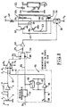
- the non-inverting input 10 of the comparator is connected, via a resistor 11, to the output 12 of a sawtooth signal generator 13, the signals of which are synchronized with the pulse image synchronization signal of a liquid crystal display; this impulse signal is applied at 14, to the generator 13.
- This generator 13 includes an operational amplifier 15 which is mounted as an integrator using a capacitor 17 which connects its input and its output and a resistor 16 which connects its input to a terminal 18 to which a voltage of reference V2.
- the rapid return of the saw teeth is achieved by a rapid analog switch 19, of the CMOS type, which is connected in parallel to the capacitor 17 and which is controlled by image synchronization pulses, shaped by a monostable rocker 20 .
- FIG. 2 which is a diagram of Amplitude (A) / time (t) curves
- the (negative) image synchronization pulses 21 are represented on the upper curve A, while the saw teeth at the output 12 of the generator 13 are shown in B.
- the adjustable continuous level applied at 8 is drawn in dashed lines at 22.
- the elements referenced 1 to 20 constitute a generator of periodic slots, of fixed frequency but of adjustable width, these slots being synchronized by the image synchronization pulses 21 of the liquid crystal screen whose rear lighting is to be produced.
- the output 24 of the comparator 9 (slots 23) and the output 25 of the monostable flip-flop 20 (pulses 21) are respectively applied to the two diodes 27, 22 of an OR circuit 26; the output of circuit 26 is coupled, by a resistor 29 followed by a fitness amplifier 30, to the control input 31 of another analog switch 32.
- This switch 32 is open when a negative slot 23 or a negative pulse 21 is applied at 31, and it is closed otherwise. It constitutes a blocking switch for an oscillator 33 for supplying alternating high-voltage to the fluorescent lamp 34.
- This oscillator 33 comprises: a transformer with a primary primary winding 35 at midpoint 36, a reaction winding 40 at midpoint 41 and a secondary winding 44, two NPN transistors 37, 38, a capacitor 39, three resistors 42, 43, 60 and a shock coil, 48.
- the transistors 37, 38 have their emitters connected to ground, their collectors respectively connected to the two ends of the winding 35 and their bases connected respectively to the resistors 42, 43; these resistors are respectively connected to the two ends of the reaction winding 40.
- the capacitor 39 is disposed between the ends of the winding 35.
- the secondary high-voltage winding 44 of the transformer has a terminal connected directly to ground and another terminal connected, through a ballast capacitor 45, to an electrode 46 of the fluorescent lamp 34; the other electrode, 47, of the lamp is connected to ground.
- the positive supply voltage + V1 of the oscillator 33 is applied, via the shock coil 48, to the midpoint 36 and, from there, through the resistor 60, to the midpoint 41, while a DC voltage negative blocking -V3 is applied, when the switch 32 is closed, on point 41, and through the resistor 60, on point 36.
- the positive voltage applied to the terminal 8 is of maximum amplitude, greater than that of the saw teeth 8, so that a level of DC voltage, of amplitude equal to -Vo, is applied at 24.
- the voltage applied to the control input 31 of the switch 32 is then a continuous level, so that the switch 32 remains permanently open and, that the oscillator 33 operates without interruption, supplying the fluorescent lamp 34 at its maximum luminance.
- the tension level 22 decreases in amplitude and comes to cut the curve 8 of the saw teeth, which generates the slots 23, of width L progressively decreasing as the cursor 3 approaches the mass, and whose front edge is synchronized with that of the pulses 21.
- the oscillator 33 then operates only during the duration of these slots 23 (curve D of FIG. 2) since, apart from these, the switch 32 is closed and, as a result, the voltage -V3 blocks the oscillator 33.
- the light intensity provided by the lamp 34 is then proportional to the width L of the slots 23, which depends on the position of the cursor 3.
- the circuit according to FIG. 3 is a representation of another device according to the invention, in its part where it differs from that according to FIG. 1; this circuit includes a series resistor 49, or "foot resistor", which is inserted between the electrode 47 of the lamp 34 and the ground. The voltage across this foot resistor 49 is applied, via a rectifier 50 and a series resistor 51, to a first input 52 of a differential amplifier 53. The other input 55 of this differential amplifier 53 receives, by the through a reference voltage V4 and an adjustable resistor 54, a DC voltage of adjustable value.
- the output of the differential amplifier 53 is connected to the control input 56 of a voltage regulator 57, which is inserted between the supply terminal + V1 and the shock inductor 48 and which is capable of varying the DC voltage on its output 58 as a function of the control voltage it receives at 56.
- the part of the device in FIG. 3, where the references 49 to 57 appear, constitutes a control loop whose role is to control the current in the resistor 49, and therefore in the lamp 34, at the value given by the reference voltage applied to input 55, value which depends on that of the adjustment resistor 54; thus it is possible to optimize the value of the supply voltage tion of the lamp 34 as a function of its operating point, thereby minimizing the dissipated power and avoiding temperature variations.
- circuit of FIG. 3 allows the lamp 34 to be started at low luminosity or at very low ambient temperature.
- the starting voltage of fluorescent lamps is a function of the temperature of the electrodes and of the enclosure which contains mercury vapor. At low light, the average current flowing through the lamp is very low and does not heat up the lamp. The ignition voltage is then higher than in the case where the lamp is very bright. This ignition voltage then also increases when the ambient temperature decreases.
- the circuit of FIG. 3 makes it possible to pair the lamps with low light.
- each lamp has its own circuit according to FIG. 3. This pairing is carried out by adjusting the resistors 54 of each circuit so that all of the lamps start for the same operating conditions. For this purpose, it is also possible to adjust the foot resistors 49, but this solution is not as good as it may increase losses.
- the minimum luminance was obtained by cutting, or modulating, the alternating voltage of the oscillator 33 by slots whose duration corresponds to the width of the image-synchronization pulses 21.
- these pulses 21 have a width of the order of microseconds.
- the width L of the pulses 23 ranging from 50 microseconds to 1000 times more, that is to say 50 milliseconds.
- a cut at 50 milliseconds corresponds to a frequency of 20 hertz, which would introduce a visible flicker ("flicker” in Anglo-Saxon literature) of the image provided by the liquid crystal screen so that in fact, in purely and simply according to this theory, the device according to the invention could not operate under the required conditions (brightness ratio of 1000/1).
- the luminosity control potentiometer, 1 can be replaced by a photodetector providing a voltage proportional to the desired luminance.
- the start of each slot 23 for cutting the sinusoidal voltage of the oscillator 33 is synchronized with the image synchronization signal of the liquid crystal screen.
Abstract
Description
Le présente invention se rapporte à un procédé et à un dispositif de gradation de lumière pour lampes fluorescentes utilisées dans une installation d'éclairage arrière d'un appareil de visualisation à écran à cristaux liquides.The present invention relates to a method and a device for dimming light for fluorescent lamps used in a rear lighting installation of a liquid crystal display device.
Les écrans à cristaux liquides, en particulier ceux entrant dans les systèmes de visualisation couleur des planches de bord d'avions et d'hélicoptères, sont éclairés par l'arrière afin d'avoir une grande luminance pour être visibles avec un confort suffisant en forte ambiance lumineuse. Cette luminance doit pouvoir être rendue variable selon les différentes conditions d'ambiance lumineuse, et il est généralement nécessaire d'asservir cette luminance en fonction des variations jour-nuit de cette ambiance. Ces variations imposent pour la source lumineuse une dynamique supérieure à 1000/1 soit, pour les lampes fluorescentes, une brillance de l'ordre de quelques Cd/m2 pour la luminance minimale et d'environ 15.000 Cd/m2 pour la luminance maximale.Liquid crystal displays, in particular those used in the color display systems of aircraft and helicopter dashboards, are backlit to provide high luminance so that they can be seen with sufficient comfort in high light bright atmosphere. This luminance must be able to be made variable according to the different conditions of light environment, and it is generally necessary to control this luminance according to the day-night variations of this environment. These variations impose for the light source a dynamic greater than 1000/1, that is, for fluorescent lamps, a brightness of the order of a few Cd / m2 for the minimum luminance and of approximately 15,000 Cd / m2 for the maximum luminance.
Il est à noter que la source lumineuse utilise des lampes fluorescentes en raison de leur excellent rendement énergétique et de leur colorimétrie qui est bien adaptée aux écrans à cristaux liquides.It should be noted that the light source uses fluorescent lamps because of their excellent energy efficiency and their colorimetry which is well suited to liquid crystal screens.
Afin d'obtenir un rendement lumineux optimal pour ces lampes fluorescentes, la tension d'alimentation appliquée entre leurs deux électrodes est une haute-tension alternative, dont l'amplitude est généralement de l'ordre de 300 à 500 volts, et dont la fréquence est de l'ordre de quelques dizaines de kilohertz.In order to obtain an optimal light output for these fluorescent lamps, the supply voltage applied between their two electrodes is an alternating high-voltage, the amplitude of which is generally of the order of 300 to 500 volts, and the frequency of which is of the order of a few tens of kilohertz.
Il est connu de faire varier la luminance d'une lampe fluorescente en faisant varier l'amplitude de sa tension d'alimentation, et par conséquent l'intensité du courant qui traverse cette lampe. Ce procédé ne permet d'obtenir une variation de luminance que dans un rapport inférieur à 10/1, ce qui est nettement insuffisant pour l'application citée ci-dessus. En outre, du fait que la tension d'amorçage des lampes fluorescentes est fonction de la température et, en particulier, augmente quand la température diminue, ce procédé de commande de luminance ne permet pas un fonctionnement dans une grande plage de température, en particulier pour les températures inférieures à 0 degré Celsius.It is known to vary the luminance of a fluorescent lamp by varying the amplitude of its supply voltage, and therefore the intensity of the current flowing through this lamp. This process does not provide a variation in luminance only in a ratio less than 10/1, which is clearly insufficient for the application cited above. In addition, since the starting voltage of fluorescent lamps is a function of temperature and, in particular, increases when the temperature decreases, this method of controlling luminance does not allow operation in a wide temperature range, in particular for temperatures below 0 degrees Celsius.
La plage de variation en luminance peut, de manière connue, être améliorée en modulant en fréquence la tension d'alimentation alternative, et plus précisément en utilisant pour cette dernière des créneaux de fréquence variable, par exemple de quelques dizaines de hertz à quelques dizaines de kilohertz. Mais, dans ce cas, pour remplir les conditions de fonctionnement précitées, il est nécessaire, pour les plus faibles luminances, de travailler à des fréquences inférieures à 15 kilohertz, mais ces fréquences peuvent provoquer des vibrations sonores. Enfin, à très faible niveau de luminance, il apparaît un battement par effet stroboscopique entre l'allumage périodique des lampes et le rafraîchissement image dont la fréquence est de l'ordre de 50 à 60 hertz. Ceci se traduit par un défilement sur l'écran d'une barre horizontale en surintensité, ce qui est un défaut inacceptable pour une visualisation de pilotage.The range of variation in luminance can, in known manner, be improved by frequency-modulating the alternating supply voltage, and more precisely by using slots of variable frequency, for example from a few tens of hertz to a few tens of kilohertz. But, in this case, to fulfill the abovementioned operating conditions, it is necessary, for the lowest luminances, to work at frequencies below 15 kilohertz, but these frequencies can cause sound vibrations. Finally, at a very low level of luminance, there appears a beat by stroboscopic effect between the periodic lighting of the lamps and the image refreshment whose frequency is of the order of 50 to 60 hertz. This results in a scrolling on the screen of a horizontal bar in overcurrent, which is an unacceptable defect for viewing piloting.
Il est également connu de faire varier la luminance d'une lampe fluorescente en effectuant un découpage de la tension d'alimentation au moyen de signaux formés de créneaux dont la largeur est réglable. Mais là encore apparaissent des problèmes d'effet stroboscopique.It is also known to vary the luminance of a fluorescent lamp by cutting the supply voltage by means of signals formed by slots whose width is adjustable. But here again, problems of stroboscopic effect appear.
L'invention vise à remédier à ces inconvénients. Ceci est obtenu en découpant la tension d'alimentation alternative d'une lampe fluorescente d'éclairage arrière d'un écran à cristaux liquides par un signal en créneaux de durée réglable en fonction de l'intensité lumineuse désirée, dont le début des créneaux est synchronisé sur le signal de "synchronlsation image" de l'écran à cristaux liquides.The invention aims to remedy these drawbacks. This is obtained by cutting the alternating supply voltage of a fluorescent lamp for rear lighting of a liquid crystal screen by a signal in slots of adjustable duration as a function of the desired light intensity, the start of the slots of which is synchronized on "image synchronization" signal from the liquid crystal display.
Selon l'invention il est proposé un procédé de gradation de lumière pour lampe fluorescente d'éclairage arrière d'écran à cristaux liquides, consistant à appliquer sur la lampe une tension d'alimentation alternative découpée par des signaux de découpage formés de créneaux de durée réglable en fonction de l'intensité lumineuse désirée, caractérisé en ce qu'il consiste à synchroniser les signaux de découpage sur un signal correspondant au signal de synchronisation-image de l'écran à cristaux liquides, divisé en fréquence par un nombre entier n supérieur à 0.According to the invention there is provided a method of dimming light for a fluorescent lamp for rear lighting of a liquid crystal screen, consisting in applying to the lamp an alternating supply voltage cut by cutting signals formed by time slots. adjustable according to the desired light intensity, characterized in that it consists in synchronizing the cutting signals on a signal corresponding to the image synchronization signal of the liquid crystal screen, divided in frequency by a whole number n greater at 0.
Selon l'invention il est également proposé un dispositif de gradation de lumière pour lampe fluorescente d'éclairage arrière d'écran à cristaux liquides, comportant un générateur de signaux de découpage formés de signaux périodiques en créneaux, de fréquence fixe et de largeur réglable, un générateur de tension alternative pour alimenter la lampe fluorescente et des moyens de blocage commandés par les signaux de découpage pour n'autoriser le fonctionnement du générateur de tension alternative que pendant la durée des créneaux, caractérisé en ce que, pour mettre en oeuvre le procédé selon l'une quelconque des revendications précédentes, il comporte des moyens pour synchroniser les signaux de découpage sur un signal correspondant au signal synchronisation-image de l'écran à cristaux liquides, divisé en fréquence par un nombre entier n supérieur à 0.According to the invention, there is also proposed a light dimming device for a fluorescent lamp for rear lighting of a liquid crystal screen, comprising a generator of cutting signals formed by periodic signals in slots, of fixed frequency and adjustable width, an alternating voltage generator for supplying the fluorescent lamp and blocking means controlled by the switching signals so as to authorize the operation of the alternating voltage generator only during the duration of the slots, characterized in that, to implement the method according to any one of the preceding claims, it comprises means for synchronizing the cutting signals to a signal corresponding to the image-synchronization signal of the liquid crystal screen, divided in frequency by an integer n greater than 0.
L'invention sera mieux comprise, et d'autres caractéristiques ressortiront de la description ci-après et des figures s'y rapportant qui représentent :
- - la figure 1, un schéma électrique d'un dispositif de gradation de lumière, selon l'invention, pour lampe fluorescente d'éclairage arrière d'un écran à cristaux liquides ;
- - la figure 2, un diagramme des temps explicatif du fonctionnement du dispositif de la figure 1 ; et
- - la figure 3, un schéma électrique partiel d'une variante de réalisation du dispositif de la figure 1. La figure 1 montre un potentiomètre de commande de luminosité 1, qui reçoit sa tension continue négative d'alimentation sur une
borne 2. Une partie de cette tension continue est prélevée par uncurseur 3 du potentiomètre 1, pour constituer un niveau de tension continue, d'amplitude réglable par déplacement ducurseur 3, qui, après mise à niveau par un amplificateur opérationnel 4 (associé à unerésistance série 5 et à une résistance de contre-réaction 6), est appliqué via unerésistance 7 à l'entrée inverseuse 8 d'un comparateur detension 9, lui-même alimenté par une tension continue +Vo, -Vo.
- - Figure 1, an electrical diagram of a light dimming device, according to the invention, for a fluorescent lamp for rear lighting of a liquid crystal screen;
- - Figure 2, a time diagram explaining the operation of the device of Figure 1; and
- - Figure 3, a partial electrical diagram of an alternative embodiment of the device of Figure 1. Figure 1 shows a brightness control potentiometer 1, which receives its negative DC supply voltage on a
terminal 2. Part of this DC voltage is taken by aslider 3 of the potentiometer 1, to constitute a level of DC voltage, of amplitude adjustable by displacement of theslider 3, which, after leveling by an operational amplifier 4 (associated with aseries resistor 5 and to a feedback resistance 6), is applied via aresistance 7 to the invertinginput 8 of avoltage comparator 9, itself supplied by a DC voltage + Vo, -Vo.
L'entrée non-inverseuse 10 du comparateur est reliée, via une résistance 11, à la sortie 12 d'un générateur de signaux en dents de scie 13, dont les signaux sont synchronisés sur le signal impulsionnel de synchronisation d'image d'un écran à cristaux liquides; ce signal impulsionnel est appliqué en 14, sur le générateur 13.The
Ce générateur 13 comporte un amplificateur opérationnel 15 qui est monté en intégrateur à l'aide d'un condensateur 17 qui relie son entrée et sa sortie et d'une résistance 16 qui relie son entrée à une borne 18 sur laquelle est appliquée une tension de référence V2.This
Le retour rapide des dents de scie est réalisé par un interrupteur analogique rapide 19, de type CMOS, qui est branché en parallèle sur le condensateur 17 et qui est commandé par des impulsions de synchronisation d'image, mises en forme par une bascule monostable 20.The rapid return of the saw teeth is achieved by a rapid
Sur la figure 2 qui est un diagramme de courbes Amplitudes (A)/temps(t), les impulsions (négatives) de synchronisation-image 21 sont représentées sur la courbe supérieure A, tandis que les dents de scie en sortie 12 du générateur 13 sont figurées en B. Le niveau continu réglable appliqué en 8 est dessiné en traits mixtes en 22.In FIG. 2 which is a diagram of Amplitude (A) / time (t) curves, the (negative) image synchronization pulses 21 are represented on the upper curve A, while the saw teeth at the
Tant que les courbes B et 22 sont sécantes, des créneaux de tension négatifs et périodiques 23, de largeur L réglable par ajustement du curseur 3, sont générés à la sortie 24 du comparateur 9, l'amplitude de ces créneaux étant égale à Vo.As long as the curves B and 22 are intersecting, negative and
Les éléments référencés 1 à 20 constituent un générateur de créneaux périodiques, de fréquence fixe mais de largeur réglable, ces créneaux étant synchronisés par les impulsions 21 de synchronisation-image de l'écran à cristaux liquides dont l'éclairage arrière est à réaliser.The elements referenced 1 to 20 constitute a generator of periodic slots, of fixed frequency but of adjustable width, these slots being synchronized by the image synchronization pulses 21 of the liquid crystal screen whose rear lighting is to be produced.
La sortie 24 du comparateur 9 (créneaux 23) et la sortie 25 de la bascule monostable 20 (impulsions 21) sont respectivement appliquées aux deux diodes 27, 22 d'un circuit OU 26 ; la sortie du circuit 26 est couplée, par une résistance 29 suivie d'un amplificateur de remise en forme 30, à l'entrée de commande 31 d'un autre interrupteur analogique 32. Cet interrupteur 32 est ouvert lorsqu'un créneau négatif 23 ou une impulsion négative 21 est appliquée en 31, et il est fermé dans le cas contraire. Il constitue un interrupteur de blocage pour un oscillateur 33 d'alimentation en haute-tension alternative de la lampe fluorescente 34.The
Cet oscillateur 33 comporte : un transformateur avec un enroulement primaire principal 35 à point milieu 36, un enroulement de réaction 40 à point milieu 41 et un enroulement secondaire 44, deux transistors NPN 37, 38, un condensateur 39, trois résistances 42, 43, 60 et une bobine de choc, 48. Les transistors 37, 38 ont leurs émetteurs reliés à la masse, leurs collecteurs respectivement reliés aux deux extrémités de l'enroulement 35 et leurs bases reliées respectivement aux résistances 42, 43 ; ces résistances sont reliées respectivement aux deux extrémités de l'enroulement de réaction 40. Le condensateur 39 est disposé entre les extrémités de l'enroulement 35. L'enroulement secondaire de haute-tension 44 du transformateur a une borne reliée directement à la masse et une autre borne reliée, à travers un condensateur ballast 45, à une électrode 46 de la lampe fluorescente 34 ; l'autre électrode, 47, de la lampe est reliée à la masse.This
La tension positive d'alimentation +V1 de l'oscillateur 33 est appliquée, via la bobine de choc 48, au point-milieu 36 et, de là, à travers la résistance 60, au point milieu 41, tandis qu'une tension continue négative de blocage -V3 est appliquée, lorsque l'interrupteur 32 est fermé, sur le point 41, et à travers la résistance 60, sur le point 36.The positive supply voltage + V1 of the
Le fonctionnement du circuit de la figure 1 est le suivant :The operation of the circuit in FIG. 1 is as follows:
Lorsque le curseur 3 du potentiomètre 3 est en position de butée haute (sur la figure 1), la tension positive appliquée sur la borne 8 est d'amplitude maximale, supérieure à celle des dents de scie 8, de sorte qu'un niveau de tension continue, d'amplitude égale à -Vo, est appliqué en 24.When the
La tension appliquée sur l'entrée de commande 31 de l'interrupteur 32 est alors un niveau continu, de sorte que l'interrupteur 32 reste ouvert en permanence et, que l'oscillateur 33 fonctionne sans interruption, alimentant la lampe fluorescente 34 à sa luminance maximale.The voltage applied to the
Lorsque, à partir de cette position de butée haute, le curseur est progressivement déplacé vers le bas (en direction de la masse), le niveau de tension 22 (figure 2) diminue en amplitude et vient couper la courbe 8 des dents de scie, ce qui génère les créneaux 23, de largeur L diminuant progressivement au fur et à mesure que le curseur 3 se rapproche de la masse, et dont le front avant est synchronisé sur celui des impulsions 21. L'oscillateur 33 ne fonctionne alors que pendant la durée de ces créneaux 23 (courbe D de la figure 2) puisque en dehors de ceux-ci, l'interrupteur 32 est fermé et que, de ce fait , la tension -V3 vient bloquer l'oscillateur 33.When, from this high stop position, the cursor is gradually moved downwards (towards the mass), the tension level 22 (FIG. 2) decreases in amplitude and comes to cut the
L'intensité lumineuse fournie par la lampe 34 est alors proportionnelle à la largeur L des créneaux 23, qui dépend de la position du curseur 3.The light intensity provided by the lamp 34 is then proportional to the width L of the
Lorsque le curseur 3 arrive en butée basse (côté masse), plus aucun signal n'apparaît en 24, mais cependant, grâce au circuit OU 28, les impulsions 21 sont néanmoins appliquées sur la borne de commande 31, ce qui fait fonctionner l'oscillateur 33 pendant la durée des impulsions de synchronisation image 21 : il est ainsi avantageusement obtenu un minimum non nul de luminosité pour la lampe 34.When the
Le circuit selon la figure 3 est une représentation d'un autre dispositif selon l'invention, dans sa partie où il se différencie de celui selon la figure 1 ; ce circuit comporte une résistance série 49, ou "résistance de pied", qui est insérée entre l'électrode 47 de la lampe 34 et la masse. La tension aux bornes de cette résistance de pied 49 est appliquée, via un redresseur 50 et une résistance série 51, à une première entrée 52 d'un amplificateur différentiel 53. L'autre entrée 55 de cet amplificateur différentiel 53 reçoit, par l'intermédiaire d'une tension de référence V4 et d'une résistance réglable 54, une tension continue de valeur réglable.The circuit according to FIG. 3 is a representation of another device according to the invention, in its part where it differs from that according to FIG. 1; this circuit includes a
La sortie de l'amplificateur différentiel 53 est reliée à l'entrée de commande 56 d'un régulateur de tension 57, qui est inséré entre la borne d'alimentation +V1 et la self de choc 48 et qui est apte à faire varier la tension continue sur sa sortie 58 en fonction de la tension de commande qu'il reçoit en 56.The output of the
La partie du dispositif de la figure 3, où apparaissent les références 49 à 57, constitue une boucle d'asservissement dont le rôle est d'asservir le courant dans la résistance 49, et donc dans la lampe 34, à la valeur donnée par la tension de référence appliquée à l'entrée 55, valeur qui dépend de celle de la résistance de réglage 54 ; ainsi il est possible d'optimiser la valeur de la tension d'alimenta tion de la lampe 34 en fonction de son point de fonctionnement, en minimisant alors la puissance dissipée et en s'affranchissant des variations de température.The part of the device in FIG. 3, where the
En outre, le circuit de la figure 3 permet un amor çage de la lampe 34 à faible luminoslté ou à très faible température ambiante.In addition, the circuit of FIG. 3 allows the lamp 34 to be started at low luminosity or at very low ambient temperature.
Il convient à ce sujet de rappeler que la tension d'amorçage des lampes fluorescentes est fonction de la température des électrodes et de l'enceinte qui contient la vapeur de mercure. A faible luminosité, le courant moyen qui traverse la lampe est très faible et n'échauffe pas la lampe. La tension d'amorçage est alors plus élevée que dans le cas où la lampe est très lumineuse. Cette tension d'amorçage s'élève alors aussi quand la température ambiante décroît.It should be remembered that the starting voltage of fluorescent lamps is a function of the temperature of the electrodes and of the enclosure which contains mercury vapor. At low light, the average current flowing through the lamp is very low and does not heat up the lamp. The ignition voltage is then higher than in the case where the lamp is very bright. This ignition voltage then also increases when the ambient temperature decreases.
En cas de non-amorçage, dû à la trop faible luminosité ou à la trop faible température ambiante, aucune tension n'est appliquée sur la borne 52 de l'amplificateur différentiel 53, de sorte que la tension maximale de commande du régulateur 57 est appliquée en 53, augmentant alors la tension effective d'alimentation de l'oscillateur 33 au dessus de sa tension d'amorçage dans ces conditions défavorables, ce qui suppose bien entendu que la tension +V1 soit d'amplitude suffisante.In the event of non-priming, due to the too low brightness or the too low ambient temperature, no voltage is applied to the
Le circuit de la figure 3 permet de réaliser un appairage des lampes à faible luminosité.The circuit of FIG. 3 makes it possible to pair the lamps with low light.
Dans le cas d'un éclairage à deux lampes fluorescentes ou plus, il est nécessaire d'appairer ces lampes pour les faibles niveaux de luminosité afin d'obtenir pour celles-ci des tensions d'amorçage identiques, sans quoi une des lampes risquerait d'éclairer et l'autre pas ; pour cela chaque lampe a son propre circuit selon la figure 3. Cet appairage est réalisé par ajustement des résistances 54 de chaque circuit pour que l'ensemble des lampes s'amorce pour les mêmes conditions de fonctionnement. Dans ce but, il est aussi possible de régler les résistances de pied 49, mais cette solution est moins bonne, car elle risque d'augmenter les pertes.In the case of lighting with two or more fluorescent lamps, it is necessary to pair these lamps for low levels of brightness in order to obtain for them identical starting voltages, otherwise one of the lamps would risk d 'enlighten and the other not; for this, each lamp has its own circuit according to FIG. 3. This pairing is carried out by adjusting the
Il a été mentionné ci-dessus que la luminance minimale était obtenue en découpant, ou modulant, la tension alternative de l'oscillateur 33 par des créneaux dont la durée correspond à la largeur des impulsions de synchronisation-image 21. Or, ces impulsions 21 ont une largeur de l'ordre de microsecondes. En théorie, pour obtenir, comme requis, une variation de luminance du tube fluorescent 34 dans un rapport de 1 à 1000, il faudrait une variation de la largeur L des impulsions 23 allant de 50 microsecondes à 1000 fois plus, c'est à dire 50 millisecondes. Or, un découpage à 50 millisecondes correspond à une fréquence de 20 hertz, ce qui introduirait un papillotement visible ("flicker" dans la littérature anglosaxonne) de l'image fournie par l'écran à cristaux liquides de sorte qu'en fait, en suivant purement et simplement cette théorie, le dispositif selon l'invention ne pourrait pas fonctionner dans les conditions requises (rapport de luminosité de 1000/1).It was mentioned above that the minimum luminance was obtained by cutting, or modulating, the alternating voltage of the
En réalité, il n'en est pas ainsi car, lorsque la lampe 34 n'est autorisée à fonctionner que pendant 50 microsecondes, elle n'a pas le temps de s'échauffer, l'opération d'amorçage elle-même ne suffisant pas à élever la température de la lampe. Son rendement lumineux à froid est alors trois fois plus faible que celui correspondant au fonctionnement continu ou quasi-continu, c'est à dire à chaud, de sorte que le rapport de 1 à 1000 en luminance est finalement obtenu en passant, pour la largeur L des impulsions de découpage de la tension sinusoïdale de l'oscillsteur 33, de 50 microsecondes à une quinzaine de millisecondes, ce qui correspond à une fréquence de découpage nettement supérieure à celles qui font apparaître un phénomène de papillotement.In reality, this is not so because, when the lamp 34 is only allowed to operate for 50 microseconds, it does not have time to heat up, the ignition operation itself is not sufficient not to raise the lamp temperature. Its cold light output is then three times lower than that corresponding to continuous or quasi-continuous operation, that is to say hot, so that the ratio of 1 to 1000 in luminance is finally obtained by the way, for the width L of the chopping pulses of the sinusoidal voltage of the
L'invention n'est pas limitée aux exemples de réalisation qui viennent d'être décrits. C'est ainsi par exemple que, dans le cadre d'un asservissement automatique sur l'ambiance lumineuse, le potentiomètre de commande de luminoslté, 1, peut être remplacé par un photodétecteur fournissant une tension proportionnelle à la luminance désirée. Dans l'exemple ci-dessus, le début de chaque créneau 23 de découpage de la tension sinusoïdale de l'oscillateur 33 est synchronisé sur le signal de synchronisation-image de l'écran à cristaux liquides. Afin d'étendre la dynamique de fonctionnement du dispositif, il est aussi possible de synchroniser ce créneau par le signal de synchronisation-image divisé en fréquence par un nombre entier supérieur à 1. Ceci n'est bien évidemment possible que si la fréquence de ce signal divisée par ce nombre n'est pas suffisamment basse pour introduire un phénomène de papillotement. Il est également possible, lorsque plusieurs lampes fluorescentes sont nécessaires, de n'utiliser qu'un seul interrupteur 32, à condition d'insérer une résistance dans la connexion entre cet interrupteur et le point 41 de chaque oscillateur propre à chacune de ces lampes.The invention is not limited to the exemplary embodiments which have just been described. This is for example that, in the context of an automatic servo-control on the lighting environment, the luminosity control potentiometer, 1, can be replaced by a photodetector providing a voltage proportional to the desired luminance. In the example above, the start of each
Claims (4)
Applications Claiming Priority (2)
| Application Number | Priority Date | Filing Date | Title |
|---|---|---|---|
| FR8908807 | 1989-06-30 | ||
| FR8908807A FR2649277B1 (en) | 1989-06-30 | 1989-06-30 | METHOD AND DEVICE FOR GRADING LIGHT FOR A FLUORESCENT LAMP FOR THE REAR LIGHTING OF A LIQUID CRYSTAL SCREEN |
Publications (2)
| Publication Number | Publication Date |
|---|---|
| EP0406116A1 true EP0406116A1 (en) | 1991-01-02 |
| EP0406116B1 EP0406116B1 (en) | 1994-01-26 |
Family
ID=9383336
Family Applications (1)
| Application Number | Title | Priority Date | Filing Date |
|---|---|---|---|
| EP90401866A Expired - Lifetime EP0406116B1 (en) | 1989-06-30 | 1990-06-28 | Process and device for dimming a fluorescent lamp of an LCD backlight |
Country Status (7)
| Country | Link |
|---|---|
| US (1) | US5105127A (en) |
| EP (1) | EP0406116B1 (en) |
| JP (1) | JPH0364895A (en) |
| CA (1) | CA2019628A1 (en) |
| DE (1) | DE69006272T2 (en) |
| FR (1) | FR2649277B1 (en) |
| HK (1) | HK83596A (en) |
Cited By (11)
| Publication number | Priority date | Publication date | Assignee | Title |
|---|---|---|---|---|
| EP0498497A2 (en) * | 1991-02-07 | 1992-08-12 | Koninklijke Philips Electronics N.V. | Circuit arrangement |
| EP0677201A1 (en) * | 1992-12-30 | 1995-10-18 | Universal Instrument Corporation | Backlighting for liquid crystal display |
| DE19511810A1 (en) * | 1994-03-30 | 1995-10-26 | Lg Electronics Inc | Projection type LCD projector lamp drive unit |
| EP0685831A1 (en) * | 1994-05-31 | 1995-12-06 | Sharp Kabushiki Kaisha | Liquid crystal display with back-light control function |
| DE4437204A1 (en) * | 1994-08-31 | 1996-03-07 | Vdo Schindling | Method of operating vehicle instrument fluorescent lamps over wide range of settings |
| EP0804052A2 (en) * | 1996-04-24 | 1997-10-29 | Patent-Treuhand-Gesellschaft für elektrische Glühlampen mbH | Control circuit for a discharge lamp |
| WO1999012401A1 (en) * | 1997-08-29 | 1999-03-11 | Robert Bosch Gmbh | Circuit for controlling at least one cold cathode fluorescent lamp |
| EP1014332A2 (en) * | 1998-12-24 | 2000-06-28 | Sharp Kabushiki Kaisha | Control device for a liquid crystal display apparatus |
| WO2000038481A1 (en) * | 1998-12-21 | 2000-06-29 | Koninklijke Philips Electronics N.V. | Circuit arrangement |
| DE19920917A1 (en) * | 1999-05-06 | 2000-11-09 | Mannesmann Vdo Ag | Display with a lighting unit |
| FR2806247A1 (en) * | 2000-03-10 | 2001-09-14 | Renault | Method of controlling an a.c. supply feeding a discharge lamp bulb used in automobile headlamps |
Families Citing this family (106)
| Publication number | Priority date | Publication date | Assignee | Title |
|---|---|---|---|---|
| JPH04333021A (en) * | 1991-05-09 | 1992-11-20 | Sharp Corp | Liquid crystal display device |
| US5287040A (en) * | 1992-07-06 | 1994-02-15 | Lestician Ballast, Inc. | Variable control, current sensing ballast |
| US5561351A (en) * | 1992-10-14 | 1996-10-01 | Diablo Research Corporation | Dimmer for electrodeless discharge lamp |
| US5910854A (en) | 1993-02-26 | 1999-06-08 | Donnelly Corporation | Electrochromic polymeric solid films, manufacturing electrochromic devices using such solid films, and processes for making such solid films and devices |
| US5323090A (en) * | 1993-06-02 | 1994-06-21 | Lestician Ballast, Inc. | Lighting system with variable control current sensing ballast |
| DE4326415B4 (en) * | 1993-08-06 | 2006-04-13 | Siemens Ag | Method for controlling a fluorescent lamp and arrangement for carrying out the method |
| US5422545A (en) * | 1993-08-19 | 1995-06-06 | Tek-Tron Enterprises, Inc. | Closed loop feedback control circuits for gas discharge lamps |
| US5428265A (en) * | 1994-02-28 | 1995-06-27 | Honeywell, Inc. | Processor controlled fluorescent lamp dimmer for aircraft liquid crystal display instruments |
| US5668663A (en) | 1994-05-05 | 1997-09-16 | Donnelly Corporation | Electrochromic mirrors and devices |
| US5668444A (en) * | 1994-06-17 | 1997-09-16 | Everbrite, Inc. | Soft-transition FSK dimmer for gaseous luminous tube lights |
| US5515261A (en) * | 1994-12-21 | 1996-05-07 | Lumion Corporation | Power factor correction circuitry |
| US6891563B2 (en) | 1996-05-22 | 2005-05-10 | Donnelly Corporation | Vehicular vision system |
| JP3905923B2 (en) * | 1995-07-10 | 2007-04-18 | コーニンクレッカ フィリップス エレクトロニクス エヌ ヴィ | Discharge lamp lighting circuit layout |
| JPH0992480A (en) * | 1995-09-21 | 1997-04-04 | Sony Corp | Cold cathode fluorescent lamp lighting device |
| GB2306810A (en) * | 1995-10-20 | 1997-05-07 | Central Research Lab Ltd | Controlling the brightness of a glow discharge |
| GB2319678B (en) * | 1996-11-25 | 2001-05-09 | Lin Ming Chao | Electronic ballast lighting power control device |
| US5838294A (en) * | 1996-12-15 | 1998-11-17 | Honeywell Inc. | Very low duty cycle pulse width modulator |
| EP0978221B1 (en) | 1997-04-24 | 2004-12-22 | Siemens Aktiengesellschaft | Circuitry for dimming a fluorescent lamp |
| DE19733939A1 (en) * | 1997-08-06 | 1999-02-11 | Mannesmann Vdo Ag | Fluorescent lamp dimming circuit |
| US6326613B1 (en) | 1998-01-07 | 2001-12-04 | Donnelly Corporation | Vehicle interior mirror assembly adapted for containing a rain sensor |
| US8294975B2 (en) | 1997-08-25 | 2012-10-23 | Donnelly Corporation | Automotive rearview mirror assembly |
| US6172613B1 (en) | 1998-02-18 | 2001-01-09 | Donnelly Corporation | Rearview mirror assembly incorporating vehicle information display |
| US6124886A (en) | 1997-08-25 | 2000-09-26 | Donnelly Corporation | Modular rearview mirror assembly |
| US6118221A (en) * | 1997-10-16 | 2000-09-12 | Tokin Corporation | Cold-cathode tube lighting circuit with protection circuit for piezoelectric transformer |
| US5939830A (en) * | 1997-12-24 | 1999-08-17 | Honeywell Inc. | Method and apparatus for dimming a lamp in a backlight of a liquid crystal display |
| US6445287B1 (en) | 2000-02-28 | 2002-09-03 | Donnelly Corporation | Tire inflation assistance monitoring system |
| US8288711B2 (en) | 1998-01-07 | 2012-10-16 | Donnelly Corporation | Interior rearview mirror system with forwardly-viewing camera and a control |
| US6477464B2 (en) | 2000-03-09 | 2002-11-05 | Donnelly Corporation | Complete mirror-based global-positioning system (GPS) navigation solution |
| US6329925B1 (en) | 1999-11-24 | 2001-12-11 | Donnelly Corporation | Rearview mirror assembly with added feature modular display |
| US6693517B2 (en) | 2000-04-21 | 2004-02-17 | Donnelly Corporation | Vehicle mirror assembly communicating wirelessly with vehicle accessories and occupants |
| US6097162A (en) * | 1998-08-17 | 2000-08-01 | Alliedsignal Inc. | Power supply system for a fluorescent lamp |
| IT1306100B1 (en) * | 1998-10-14 | 2001-05-29 | Space Cannon Vh Srl | ELECTRONIC SYSTEM FOR THE GENERATION AND CONTROL OF LIGHT EFFECTS ON PROJECTORS |
| US6900600B2 (en) | 1998-12-11 | 2005-05-31 | Monolithic Power Systems, Inc. | Method for starting a discharge lamp using high energy initial pulse |
| US6114814A (en) * | 1998-12-11 | 2000-09-05 | Monolithic Power Systems, Inc. | Apparatus for controlling a discharge lamp in a backlighted display |
| DE19903015A1 (en) * | 1999-01-26 | 2000-08-03 | Vogt Electronic Ag | Dimmable ballast apparatus for cold cathode fluorescent lamps, has controllable voltage source as pulse width/frequency controllable AC generator with output is supplied to intermediate tapping of first part-winding. |
| US6153981A (en) * | 1999-02-19 | 2000-11-28 | General Electric Company | Strobing light control adapter |
| US6191539B1 (en) | 1999-03-26 | 2001-02-20 | Korry Electronics Co | Fluorescent lamp with integral conductive traces for extending low-end luminance and heating the lamp tube |
| US6259615B1 (en) | 1999-07-22 | 2001-07-10 | O2 Micro International Limited | High-efficiency adaptive DC/AC converter |
| US6804129B2 (en) | 1999-07-22 | 2004-10-12 | 02 Micro International Limited | High-efficiency adaptive DC/AC converter |
| TW472186B (en) * | 2000-02-11 | 2002-01-11 | Mitac Int Corp | Power saving circuit and method of display light source |
| AU2001243285A1 (en) | 2000-03-02 | 2001-09-12 | Donnelly Corporation | Video mirror systems incorporating an accessory module |
| US7167796B2 (en) | 2000-03-09 | 2007-01-23 | Donnelly Corporation | Vehicle navigation system for use with a telematics system |
| US7370983B2 (en) | 2000-03-02 | 2008-05-13 | Donnelly Corporation | Interior mirror assembly with display |
| WO2007053710A2 (en) | 2005-11-01 | 2007-05-10 | Donnelly Corporation | Interior rearview mirror with display |
| AU2001251230A1 (en) | 2000-05-12 | 2001-11-26 | John Chou | Integrated circuit for lamp heating and dimming control |
| US6608450B2 (en) | 2000-06-13 | 2003-08-19 | Lighttech Group, Inc. | High frequency, high efficiency electronic lighting system with sodium lamp |
| US6555971B1 (en) | 2000-06-13 | 2003-04-29 | Lighttech Group, Inc. | High frequency, high efficiency quick restart lighting system |
| US6555972B1 (en) | 2000-06-13 | 2003-04-29 | Lighttech, Group, Inc. | High frequency, high efficiency electronic lighting system with metal halide lamp |
| US6344717B1 (en) | 2000-10-12 | 2002-02-05 | Lighttech Group, Inc | High frequency, high efficiency electronic lighting system with iodine and/or bromine-based metal halide high pressure discharge lamp |
| US6501234B2 (en) | 2001-01-09 | 2002-12-31 | 02 Micro International Limited | Sequential burst mode activation circuit |
| US7255451B2 (en) | 2002-09-20 | 2007-08-14 | Donnelly Corporation | Electro-optic mirror cell |
| US7581859B2 (en) | 2005-09-14 | 2009-09-01 | Donnelly Corp. | Display device for exterior rearview mirror |
| EP1363810B1 (en) | 2001-01-23 | 2007-05-30 | Donnelly Corporation | Improved vehicular lighting system |
| US6570344B2 (en) | 2001-05-07 | 2003-05-27 | O2Micro International Limited | Lamp grounding and leakage current detection system |
| WO2002095922A1 (en) * | 2001-05-24 | 2002-11-28 | Comair Rotron Inc. | Stator with multiple winding configurations |
| KR100878222B1 (en) * | 2001-07-03 | 2009-01-13 | 삼성전자주식회사 | Apparatus for supplying power for a liquid crystal display |
| US6731075B2 (en) * | 2001-11-02 | 2004-05-04 | Ampr Llc | Method and apparatus for lighting a discharge lamp |
| US7515446B2 (en) * | 2002-04-24 | 2009-04-07 | O2Micro International Limited | High-efficiency adaptive DC/AC converter |
| US6918674B2 (en) | 2002-05-03 | 2005-07-19 | Donnelly Corporation | Vehicle rearview mirror system |
| US6856519B2 (en) | 2002-05-06 | 2005-02-15 | O2Micro International Limited | Inverter controller |
| US6841947B2 (en) * | 2002-05-14 | 2005-01-11 | Garmin At, Inc. | Systems and methods for controlling brightness of an avionics display |
| US7329013B2 (en) | 2002-06-06 | 2008-02-12 | Donnelly Corporation | Interior rearview mirror system with compass |
| EP1514246A4 (en) | 2002-06-06 | 2008-04-16 | Donnelly Corp | Interior rearview mirror system with compass |
| US6873322B2 (en) * | 2002-06-07 | 2005-03-29 | 02Micro International Limited | Adaptive LCD power supply circuit |
| US6756769B2 (en) | 2002-06-20 | 2004-06-29 | O2Micro International Limited | Enabling circuit for avoiding negative voltage transients |
| US6949912B2 (en) | 2002-06-20 | 2005-09-27 | 02Micro International Limited | Enabling circuit for avoiding negative voltage transients |
| KR100870007B1 (en) * | 2002-06-25 | 2008-11-21 | 삼성전자주식회사 | Apparatus of driving backlight unit for liquid crystal display |
| US7310177B2 (en) | 2002-09-20 | 2007-12-18 | Donnelly Corporation | Electro-optic reflective element assembly |
| EP1543358A2 (en) | 2002-09-20 | 2005-06-22 | Donnelly Corporation | Mirror reflective element assembly |
| US6979959B2 (en) * | 2002-12-13 | 2005-12-27 | Microsemi Corporation | Apparatus and method for striking a fluorescent lamp |
| US6778415B2 (en) * | 2003-01-22 | 2004-08-17 | O2Micro, Inc. | Controller electrical power circuit supplying energy to a display device |
| JP3096242U (en) * | 2003-03-04 | 2003-09-12 | 船井電機株式会社 | Television receivers and cold cathode tube dimmers |
| US7057611B2 (en) * | 2003-03-25 | 2006-06-06 | 02Micro International Limited | Integrated power supply for an LCD panel |
| US6936975B2 (en) * | 2003-04-15 | 2005-08-30 | 02Micro International Limited | Power supply for an LCD panel |
| US7348735B2 (en) * | 2003-05-01 | 2008-03-25 | Inventive Holdings Llc | Lamp driver |
| US7289037B2 (en) | 2003-05-19 | 2007-10-30 | Donnelly Corporation | Mirror assembly for vehicle |
| US6897698B1 (en) | 2003-05-30 | 2005-05-24 | O2Micro International Limited | Phase shifting and PWM driving circuits and methods |
| DE10340198B4 (en) * | 2003-08-27 | 2009-03-12 | Institut für Mikroelektronik- und Mechatronik-Systeme gGmbH | Circuit arrangement for dimming gas discharge lamps and method for their operation |
| US7187139B2 (en) | 2003-09-09 | 2007-03-06 | Microsemi Corporation | Split phase inverters for CCFL backlight system |
| US7183727B2 (en) * | 2003-09-23 | 2007-02-27 | Microsemi Corporation | Optical and temperature feedbacks to control display brightness |
| US6919694B2 (en) * | 2003-10-02 | 2005-07-19 | Monolithic Power Systems, Inc. | Fixed operating frequency inverter for cold cathode fluorescent lamp having strike frequency adjusted by voltage to current phase relationship |
| US7446924B2 (en) | 2003-10-02 | 2008-11-04 | Donnelly Corporation | Mirror reflective element assembly including electronic component |
| US7308341B2 (en) | 2003-10-14 | 2007-12-11 | Donnelly Corporation | Vehicle communication system |
| US7468722B2 (en) * | 2004-02-09 | 2008-12-23 | Microsemi Corporation | Method and apparatus to control display brightness with ambient light correction |
| US7394209B2 (en) * | 2004-02-11 | 2008-07-01 | 02 Micro International Limited | Liquid crystal display system with lamp feedback |
| US7112929B2 (en) * | 2004-04-01 | 2006-09-26 | Microsemi Corporation | Full-bridge and half-bridge compatible driver timing schedule for direct drive backlight system |
| US7755595B2 (en) | 2004-06-07 | 2010-07-13 | Microsemi Corporation | Dual-slope brightness control for transflective displays |
| EP1871148A1 (en) * | 2005-01-25 | 2007-12-26 | Matsushita Electric Industrial Co., Ltd. | Backlight control apparatus and display apparatus |
| EP1883855B1 (en) | 2005-05-16 | 2011-07-20 | Donnelly Corporation | Vehicle mirror assembly with indicia at reflective element |
| US7414371B1 (en) | 2005-11-21 | 2008-08-19 | Microsemi Corporation | Voltage regulation loop with variable gain control for inverter circuit |
| CN101433130A (en) * | 2006-04-24 | 2009-05-13 | 松下电器产业株式会社 | Backlight controller and display |
| US7569998B2 (en) | 2006-07-06 | 2009-08-04 | Microsemi Corporation | Striking and open lamp regulation for CCFL controller |
| DE102006035071A1 (en) * | 2006-07-28 | 2008-01-31 | Minebea Co., Ltd., Kitasaku | Lamp e.g. gas-discharge lamp, brightness adjusting device for background lighting, has modulator applying voltage to lamp, such that voltage is sufficient and reduced during intervals, where transitions between intervals are decelerated |
| TWI346925B (en) * | 2006-08-28 | 2011-08-11 | Au Optronics Corp | Display and apparatus and method for power saving thereof |
| KR101311630B1 (en) * | 2006-10-12 | 2013-09-26 | 엘지디스플레이 주식회사 | Apparatus and method for driving LCD |
| US7541751B2 (en) * | 2007-03-05 | 2009-06-02 | Mdl Corporation | Soft start control circuit for lighting |
| CN101364199B (en) * | 2007-08-06 | 2012-01-18 | 鸿富锦精密工业(深圳)有限公司 | Serial communication monitoring system and monitoring equipment |
| US8154418B2 (en) | 2008-03-31 | 2012-04-10 | Magna Mirrors Of America, Inc. | Interior rearview mirror system |
| US8313266B2 (en) * | 2008-08-28 | 2012-11-20 | Mitsubishi Heavy Industries, Ltd. | Construction method and construction apparatus for offshore wind turbine generator |
| US9487144B2 (en) | 2008-10-16 | 2016-11-08 | Magna Mirrors Of America, Inc. | Interior mirror assembly with display |
| US8093839B2 (en) * | 2008-11-20 | 2012-01-10 | Microsemi Corporation | Method and apparatus for driving CCFL at low burst duty cycle rates |
| GB201209131D0 (en) | 2012-05-24 | 2012-07-04 | Subsea 7 Contracting Norway As | Handling loads in offshore environments |
| US8878882B2 (en) | 2012-05-29 | 2014-11-04 | Gentex Corporation | Segmented edge-lit backlight assembly for a display |
| CN103336664B (en) * | 2013-06-05 | 2016-10-05 | 南京熊猫电子股份有限公司 | A kind of device and method realizing control of display backlight with soft keyboard |
| KR101778173B1 (en) | 2013-09-04 | 2017-09-13 | 젠텍스 코포레이션 | A rearview assembly of a vehicle for displaying images |
| US9788402B2 (en) | 2015-03-23 | 2017-10-10 | Luxor Scientific, Inc | Enhanced variable control, current sensing drivers with zeta scan |
Citations (5)
| Publication number | Priority date | Publication date | Assignee | Title |
|---|---|---|---|---|
| US4219760A (en) * | 1979-03-22 | 1980-08-26 | General Electric Company | SEF Lamp dimming |
| DE3048531A1 (en) * | 1979-12-27 | 1981-09-17 | Canon K.K., Tokyo | EXPOSURE CONTROL DEVICE |
| EP0152026A1 (en) * | 1984-02-03 | 1985-08-21 | Omega Electronics S.A. | Feeding device for controlling the light intensity of at least one discharge lamp, and use of this device |
| FR2584845A1 (en) * | 1985-07-12 | 1987-01-16 | Canon Kk | LIQUID CRYSTAL APPARATUS AND METHOD OF CONTROLLING THE SAME |
| EP0329571A1 (en) * | 1988-01-21 | 1989-08-23 | STMicroelectronics S.A. | Demagnetization control device for a switch-mode supply with primary and secondary regulation |
Family Cites Families (5)
| Publication number | Priority date | Publication date | Assignee | Title |
|---|---|---|---|---|
| EP0104264A1 (en) * | 1982-09-24 | 1984-04-04 | White Castle System, Inc. | Adjustable electrical power control for gas discharge lamps and the like |
| US4682083A (en) * | 1984-10-29 | 1987-07-21 | General Electric Company | Fluorescent lamp dimming adaptor kit |
| DE3528838A1 (en) * | 1985-08-10 | 1987-02-12 | Diehl Gmbh & Co | IGNITION AND DIMMING CONTROL FOR A FLUORESCENT TUBE |
| JP2698580B2 (en) * | 1987-03-09 | 1998-01-19 | 沖電気工業株式会社 | Voltage / pulse width conversion circuit |
| US5001386B1 (en) * | 1989-12-22 | 1996-10-15 | Lutron Electronics Co | Circuit for dimming gas discharge lamps without introducing striations |
-
1989
- 1989-06-30 FR FR8908807A patent/FR2649277B1/en not_active Expired - Lifetime
-
1990
- 1990-06-21 US US07/541,766 patent/US5105127A/en not_active Expired - Fee Related
- 1990-06-22 CA CA002019628A patent/CA2019628A1/en not_active Abandoned
- 1990-06-28 EP EP90401866A patent/EP0406116B1/en not_active Expired - Lifetime
- 1990-06-28 DE DE90401866T patent/DE69006272T2/en not_active Expired - Lifetime
- 1990-06-29 JP JP2170357A patent/JPH0364895A/en active Pending
-
1996
- 1996-05-09 HK HK83596A patent/HK83596A/en not_active IP Right Cessation
Patent Citations (5)
| Publication number | Priority date | Publication date | Assignee | Title |
|---|---|---|---|---|
| US4219760A (en) * | 1979-03-22 | 1980-08-26 | General Electric Company | SEF Lamp dimming |
| DE3048531A1 (en) * | 1979-12-27 | 1981-09-17 | Canon K.K., Tokyo | EXPOSURE CONTROL DEVICE |
| EP0152026A1 (en) * | 1984-02-03 | 1985-08-21 | Omega Electronics S.A. | Feeding device for controlling the light intensity of at least one discharge lamp, and use of this device |
| FR2584845A1 (en) * | 1985-07-12 | 1987-01-16 | Canon Kk | LIQUID CRYSTAL APPARATUS AND METHOD OF CONTROLLING THE SAME |
| EP0329571A1 (en) * | 1988-01-21 | 1989-08-23 | STMicroelectronics S.A. | Demagnetization control device for a switch-mode supply with primary and secondary regulation |
Non-Patent Citations (1)
| Title |
|---|
| SID INTERNATIONAL SYMPOSIUM: "DIGEST OF TECHNICAL PAPERS VOL.20" 18 mai 1989, BALTIMORE * |
Cited By (18)
| Publication number | Priority date | Publication date | Assignee | Title |
|---|---|---|---|---|
| EP0498497A3 (en) * | 1991-02-07 | 1993-05-26 | Koninkl Philips Electronics Nv | Circuit arrangement |
| EP0498497A2 (en) * | 1991-02-07 | 1992-08-12 | Koninklijke Philips Electronics N.V. | Circuit arrangement |
| EP0677201A4 (en) * | 1992-12-30 | 1996-11-06 | Avionic Displays Corp | Backlighting for liquid crystal display. |
| EP0677201A1 (en) * | 1992-12-30 | 1995-10-18 | Universal Instrument Corporation | Backlighting for liquid crystal display |
| DE19511810A1 (en) * | 1994-03-30 | 1995-10-26 | Lg Electronics Inc | Projection type LCD projector lamp drive unit |
| US5844540A (en) * | 1994-05-31 | 1998-12-01 | Sharp Kabushiki Kaisha | Liquid crystal display with back-light control function |
| EP0685831A1 (en) * | 1994-05-31 | 1995-12-06 | Sharp Kabushiki Kaisha | Liquid crystal display with back-light control function |
| DE4437204A1 (en) * | 1994-08-31 | 1996-03-07 | Vdo Schindling | Method of operating vehicle instrument fluorescent lamps over wide range of settings |
| EP0804052A2 (en) * | 1996-04-24 | 1997-10-29 | Patent-Treuhand-Gesellschaft für elektrische Glühlampen mbH | Control circuit for a discharge lamp |
| EP0804052A3 (en) * | 1996-04-24 | 1999-04-07 | Patent-Treuhand-Gesellschaft für elektrische Glühlampen mbH | Control circuit for a discharge lamp |
| WO1999012401A1 (en) * | 1997-08-29 | 1999-03-11 | Robert Bosch Gmbh | Circuit for controlling at least one cold cathode fluorescent lamp |
| WO2000038481A1 (en) * | 1998-12-21 | 2000-06-29 | Koninklijke Philips Electronics N.V. | Circuit arrangement |
| US6278244B1 (en) | 1998-12-21 | 2001-08-21 | U.S. Philips Corporation | Circuit arrangement for operating a discharge lamp in synchronism with an image writing signal |
| EP1014332A2 (en) * | 1998-12-24 | 2000-06-28 | Sharp Kabushiki Kaisha | Control device for a liquid crystal display apparatus |
| EP1014332A3 (en) * | 1998-12-24 | 2000-09-06 | Sharp Kabushiki Kaisha | Control device for a liquid crystal display apparatus |
| US6429839B1 (en) | 1998-12-24 | 2002-08-06 | Sharp Kabushiki Kaisha | Liquid crystal display apparatus and electronic device for providing control signal to liquid crystal display apparatus |
| DE19920917A1 (en) * | 1999-05-06 | 2000-11-09 | Mannesmann Vdo Ag | Display with a lighting unit |
| FR2806247A1 (en) * | 2000-03-10 | 2001-09-14 | Renault | Method of controlling an a.c. supply feeding a discharge lamp bulb used in automobile headlamps |
Also Published As
| Publication number | Publication date |
|---|---|
| FR2649277A1 (en) | 1991-01-04 |
| EP0406116B1 (en) | 1994-01-26 |
| DE69006272T2 (en) | 1994-05-05 |
| FR2649277B1 (en) | 1996-05-31 |
| DE69006272D1 (en) | 1994-03-10 |
| HK83596A (en) | 1996-05-17 |
| JPH0364895A (en) | 1991-03-20 |
| CA2019628A1 (en) | 1990-12-31 |
| US5105127A (en) | 1992-04-14 |
Similar Documents
| Publication | Publication Date | Title |
|---|---|---|
| EP0406116B1 (en) | Process and device for dimming a fluorescent lamp of an LCD backlight | |
| EP0288924B1 (en) | Power supply device for a discharge lamp | |
| FR2923625A1 (en) | METHOD FOR GENERATING MIXED LIGHT COLORS | |
| WO2015005465A1 (en) | Display device and drive method for backlight | |
| FR3013937A1 (en) | ATTACK CIRCUIT WITH SEMICONDUCTOR LIGHT SOURCE AND METHOD OF OPERATING AN ATTACK CIRCUIT | |
| EP0152026B1 (en) | Feeding device for controlling the light intensity of at least one discharge lamp, and use of this device | |
| FR2882870A1 (en) | ROYER OSCILLATOR WITH ELECTRONIC DISCHARGE | |
| EP0390699A1 (en) | Powering circuit for an arclamp, especially for a car headlight | |
| EP0082031A1 (en) | Circuit for controlling the light intensity of a fluorescent lamp fed by a direct current | |
| FR2752135A1 (en) | METHODS AND DEVICES FOR CONTROLLING THE INTENSITY OF FLUORESCENT LAMPS | |
| KR100899022B1 (en) | Cold-cathode fluorescent lamp multiple lamp current matching circuit | |
| FR2874151A1 (en) | LAMP IGNITION APPARATUS | |
| KR20080030063A (en) | Method of driving a discharge lamp in a projection system, and driving unit | |
| FR2863815A1 (en) | APPARATUS AND METHOD FOR SUPPLYING A LAMP OF A LIQUID CRYSTAL DISPLAY DEVICE | |
| KR100495760B1 (en) | Very low duty cycle pulse width modulator | |
| EP2216675A1 (en) | NVG-compatible light-emitting diode lighting device | |
| JPH10505943A (en) | Discharge lamp lighting circuit layout | |
| EP0356288B1 (en) | Method and device for back-lighting a liquid-crystal matrix screen | |
| FR2550043A1 (en) | Ballast circuit with illumination level control | |
| EP2215891A1 (en) | Method for controlling a servo system | |
| FR2976150A1 (en) | DEVICE FOR CONTROLLING VERY LUMINOUS DYNAMIC LIGHT-EMITTING DIODES FOR DISPLAY SCREEN | |
| JP4865308B2 (en) | Discharge lamp lighting device | |
| BE880305R (en) | PRESET DIGITAL DIGITAL DIMMER WITH LIGHT CONTROL AND ANTI-GLARE DEVICE | |
| FR3023671B1 (en) | FEEDING METHOD AND LIGHTING SYSTEM | |
| JPH1197196A (en) | Dimming device for liquid crystal display |
Legal Events
| Date | Code | Title | Description |
|---|---|---|---|
| PUAI | Public reference made under article 153(3) epc to a published international application that has entered the european phase |
Free format text: ORIGINAL CODE: 0009012 |
|
| AK | Designated contracting states |
Kind code of ref document: A1 Designated state(s): DE GB IT NL SE |
|
| 17P | Request for examination filed |
Effective date: 19910617 |
|
| 17Q | First examination report despatched |
Effective date: 19930517 |
|
| GRAA | (expected) grant |
Free format text: ORIGINAL CODE: 0009210 |
|
| AK | Designated contracting states |
Kind code of ref document: B1 Designated state(s): DE GB IT NL SE |
|
| ITF | It: translation for a ep patent filed |
Owner name: JACOBACCI CASETTA & PERANI S.P.A. |
|
| RAP2 | Party data changed (patent owner data changed or rights of a patent transferred) |
Owner name: THOMSON-CSF |
|
| REF | Corresponds to: |
Ref document number: 69006272 Country of ref document: DE Date of ref document: 19940310 |
|
| GBT | Gb: translation of ep patent filed (gb section 77(6)(a)/1977) |
Effective date: 19940308 |
|
| NLT2 | Nl: modifications (of names), taken from the european patent patent bulletin |
Owner name: THOMSON-CSF TE PARIJS, FRANKRIJK. |
|
| PLBE | No opposition filed within time limit |
Free format text: ORIGINAL CODE: 0009261 |
|
| STAA | Information on the status of an ep patent application or granted ep patent |
Free format text: STATUS: NO OPPOSITION FILED WITHIN TIME LIMIT |
|
| 26N | No opposition filed | ||
| EAL | Se: european patent in force in sweden |
Ref document number: 90401866.0 |
|
| PGFP | Annual fee paid to national office [announced via postgrant information from national office to epo] |
Ref country code: DE Payment date: 19980515 Year of fee payment: 9 |
|
| PGFP | Annual fee paid to national office [announced via postgrant information from national office to epo] |
Ref country code: SE Payment date: 19990514 Year of fee payment: 10 |
|
| PG25 | Lapsed in a contracting state [announced via postgrant information from national office to epo] |
Ref country code: DE Free format text: LAPSE BECAUSE OF THE APPLICANT RENOUNCES Effective date: 19990602 |
|
| PGFP | Annual fee paid to national office [announced via postgrant information from national office to epo] |
Ref country code: GB Payment date: 20000519 Year of fee payment: 11 |
|
| PGFP | Annual fee paid to national office [announced via postgrant information from national office to epo] |
Ref country code: NL Payment date: 20000607 Year of fee payment: 11 |
|
| PG25 | Lapsed in a contracting state [announced via postgrant information from national office to epo] |
Ref country code: SE Free format text: LAPSE BECAUSE OF NON-PAYMENT OF DUE FEES Effective date: 20000629 |
|
| EUG | Se: european patent has lapsed |
Ref document number: 90401866.0 |
|
| PG25 | Lapsed in a contracting state [announced via postgrant information from national office to epo] |
Ref country code: GB Free format text: LAPSE BECAUSE OF NON-PAYMENT OF DUE FEES Effective date: 20010628 |
|
| PG25 | Lapsed in a contracting state [announced via postgrant information from national office to epo] |
Ref country code: NL Free format text: LAPSE BECAUSE OF NON-PAYMENT OF DUE FEES Effective date: 20020101 |
|
| GBPC | Gb: european patent ceased through non-payment of renewal fee |
Effective date: 20010628 |
|
| NLV4 | Nl: lapsed or anulled due to non-payment of the annual fee |
Effective date: 20020101 |
|
| PG25 | Lapsed in a contracting state [announced via postgrant information from national office to epo] |
Ref country code: IT Free format text: LAPSE BECAUSE OF NON-PAYMENT OF DUE FEES;WARNING: LAPSES OF ITALIAN PATENTS WITH EFFECTIVE DATE BEFORE 2007 MAY HAVE OCCURRED AT ANY TIME BEFORE 2007. THE CORRECT EFFECTIVE DATE MAY BE DIFFERENT FROM THE ONE RECORDED. Effective date: 20050628 |