EP0402738A2 - Nickel foam - Google Patents
Nickel foam Download PDFInfo
- Publication number
- EP0402738A2 EP0402738A2 EP90110606A EP90110606A EP0402738A2 EP 0402738 A2 EP0402738 A2 EP 0402738A2 EP 90110606 A EP90110606 A EP 90110606A EP 90110606 A EP90110606 A EP 90110606A EP 0402738 A2 EP0402738 A2 EP 0402738A2
- Authority
- EP
- European Patent Office
- Prior art keywords
- nickel
- foam
- open
- foam structure
- cell
- Prior art date
- Legal status (The legal status is an assumption and is not a legal conclusion. Google has not performed a legal analysis and makes no representation as to the accuracy of the status listed.)
- Granted
Links
Images


Classifications
-
- C—CHEMISTRY; METALLURGY
- C22—METALLURGY; FERROUS OR NON-FERROUS ALLOYS; TREATMENT OF ALLOYS OR NON-FERROUS METALS
- C22B—PRODUCTION AND REFINING OF METALS; PRETREATMENT OF RAW MATERIALS
- C22B23/00—Obtaining nickel or cobalt
-
- B—PERFORMING OPERATIONS; TRANSPORTING
- B01—PHYSICAL OR CHEMICAL PROCESSES OR APPARATUS IN GENERAL
- B01D—SEPARATION
- B01D39/00—Filtering material for liquid or gaseous fluids
- B01D39/14—Other self-supporting filtering material ; Other filtering material
- B01D39/20—Other self-supporting filtering material ; Other filtering material of inorganic material, e.g. asbestos paper, metallic filtering material of non-woven wires
- B01D39/2027—Metallic material
- B01D39/2051—Metallic foam
-
- B—PERFORMING OPERATIONS; TRANSPORTING
- B22—CASTING; POWDER METALLURGY
- B22F—WORKING METALLIC POWDER; MANUFACTURE OF ARTICLES FROM METALLIC POWDER; MAKING METALLIC POWDER; APPARATUS OR DEVICES SPECIALLY ADAPTED FOR METALLIC POWDER
- B22F3/00—Manufacture of workpieces or articles from metallic powder characterised by the manner of compacting or sintering; Apparatus specially adapted therefor ; Presses and furnaces
- B22F3/10—Sintering only
- B22F3/11—Making porous workpieces or articles
- B22F3/1121—Making porous workpieces or articles by using decomposable, meltable or sublimatable fillers
- B22F3/1137—Making porous workpieces or articles by using decomposable, meltable or sublimatable fillers by coating porous removable preforms
-
- C—CHEMISTRY; METALLURGY
- C22—METALLURGY; FERROUS OR NON-FERROUS ALLOYS; TREATMENT OF ALLOYS OR NON-FERROUS METALS
- C22B—PRODUCTION AND REFINING OF METALS; PRETREATMENT OF RAW MATERIALS
- C22B5/00—General methods of reducing to metals
- C22B5/02—Dry methods smelting of sulfides or formation of mattes
- C22B5/20—Dry methods smelting of sulfides or formation of mattes from metal carbonyls
-
- C—CHEMISTRY; METALLURGY
- C23—COATING METALLIC MATERIAL; COATING MATERIAL WITH METALLIC MATERIAL; CHEMICAL SURFACE TREATMENT; DIFFUSION TREATMENT OF METALLIC MATERIAL; COATING BY VACUUM EVAPORATION, BY SPUTTERING, BY ION IMPLANTATION OR BY CHEMICAL VAPOUR DEPOSITION, IN GENERAL; INHIBITING CORROSION OF METALLIC MATERIAL OR INCRUSTATION IN GENERAL
- C23C—COATING METALLIC MATERIAL; COATING MATERIAL WITH METALLIC MATERIAL; SURFACE TREATMENT OF METALLIC MATERIAL BY DIFFUSION INTO THE SURFACE, BY CHEMICAL CONVERSION OR SUBSTITUTION; COATING BY VACUUM EVAPORATION, BY SPUTTERING, BY ION IMPLANTATION OR BY CHEMICAL VAPOUR DEPOSITION, IN GENERAL
- C23C16/00—Chemical coating by decomposition of gaseous compounds, without leaving reaction products of surface material in the coating, i.e. chemical vapour deposition [CVD] processes
- C23C16/06—Chemical coating by decomposition of gaseous compounds, without leaving reaction products of surface material in the coating, i.e. chemical vapour deposition [CVD] processes characterised by the deposition of metallic material
- C23C16/16—Chemical coating by decomposition of gaseous compounds, without leaving reaction products of surface material in the coating, i.e. chemical vapour deposition [CVD] processes characterised by the deposition of metallic material from metal carbonyl compounds
-
- H—ELECTRICITY
- H01—ELECTRIC ELEMENTS
- H01M—PROCESSES OR MEANS, e.g. BATTERIES, FOR THE DIRECT CONVERSION OF CHEMICAL ENERGY INTO ELECTRICAL ENERGY
- H01M4/00—Electrodes
- H01M4/02—Electrodes composed of, or comprising, active material
- H01M4/64—Carriers or collectors
- H01M4/70—Carriers or collectors characterised by shape or form
- H01M4/80—Porous plates, e.g. sintered carriers
- H01M4/808—Foamed, spongy materials
-
- B—PERFORMING OPERATIONS; TRANSPORTING
- B22—CASTING; POWDER METALLURGY
- B22F—WORKING METALLIC POWDER; MANUFACTURE OF ARTICLES FROM METALLIC POWDER; MAKING METALLIC POWDER; APPARATUS OR DEVICES SPECIALLY ADAPTED FOR METALLIC POWDER
- B22F2998/00—Supplementary information concerning processes or compositions relating to powder metallurgy
-
- Y—GENERAL TAGGING OF NEW TECHNOLOGICAL DEVELOPMENTS; GENERAL TAGGING OF CROSS-SECTIONAL TECHNOLOGIES SPANNING OVER SEVERAL SECTIONS OF THE IPC; TECHNICAL SUBJECTS COVERED BY FORMER USPC CROSS-REFERENCE ART COLLECTIONS [XRACs] AND DIGESTS
- Y02—TECHNOLOGIES OR APPLICATIONS FOR MITIGATION OR ADAPTATION AGAINST CLIMATE CHANGE
- Y02E—REDUCTION OF GREENHOUSE GAS [GHG] EMISSIONS, RELATED TO ENERGY GENERATION, TRANSMISSION OR DISTRIBUTION
- Y02E60/00—Enabling technologies; Technologies with a potential or indirect contribution to GHG emissions mitigation
- Y02E60/10—Energy storage using batteries
-
- Y—GENERAL TAGGING OF NEW TECHNOLOGICAL DEVELOPMENTS; GENERAL TAGGING OF CROSS-SECTIONAL TECHNOLOGIES SPANNING OVER SEVERAL SECTIONS OF THE IPC; TECHNICAL SUBJECTS COVERED BY FORMER USPC CROSS-REFERENCE ART COLLECTIONS [XRACs] AND DIGESTS
- Y10—TECHNICAL SUBJECTS COVERED BY FORMER USPC
- Y10T—TECHNICAL SUBJECTS COVERED BY FORMER US CLASSIFICATION
- Y10T428/00—Stock material or miscellaneous articles
- Y10T428/12—All metal or with adjacent metals
- Y10T428/12479—Porous [e.g., foamed, spongy, cracked, etc.]
-
- Y—GENERAL TAGGING OF NEW TECHNOLOGICAL DEVELOPMENTS; GENERAL TAGGING OF CROSS-SECTIONAL TECHNOLOGIES SPANNING OVER SEVERAL SECTIONS OF THE IPC; TECHNICAL SUBJECTS COVERED BY FORMER USPC CROSS-REFERENCE ART COLLECTIONS [XRACs] AND DIGESTS
- Y10—TECHNICAL SUBJECTS COVERED BY FORMER USPC
- Y10T—TECHNICAL SUBJECTS COVERED BY FORMER US CLASSIFICATION
- Y10T428/00—Stock material or miscellaneous articles
- Y10T428/12—All metal or with adjacent metals
- Y10T428/12486—Laterally noncoextensive components [e.g., embedded, etc.]
Definitions
- the invention relates to the field of nickel foams. More particularly, the invention relates to nickel foam battery plaques having improved conductivity, porosity, foam cell size, capacity to hold active mass, strength and a method for producing the improved battery plaques.
- Battery plaques have conventionally been formed by sintering nickel powder onto a nickel coated steel plate. Porosities achieved in the sintered plaque have been generally limited to porosities in the 80% range. These 80% range porosities, in turn, limit the amount of active mass that may be held in the plaque which limits the battery capacity. Low porosity and decreased capacity for holding active mass has long been a problem limiting the battery performance.
- Nickel plaques having increased porosity for batteries have been experimentally formed by chemical vapor deposition of nickel carbonyl on carbon felt.
- the battery plaques were formed by depositing nickel onto a carbon felt substrate and using the nickel coated felt substrate to support active mass.
- carbon felt process There are several problems with the carbon felt process.
- Previous experimental attempts at chemical vapor deposition of polymer fibers for batteries produced a product having an inferior nickel coating having inferior mechanical stability which was unsuitable for battery plaques.
- nickel battery plaques have been produced by an alternative electrochemical method (Matsamoto U.S. Pat. No. 4,251,603).
- Nickel is electroplated onto a polyurethane foam and sintered to form nickel foam.
- polyurethane foam is made conductive by immersion of the foam into a colloidal graphite dispersion and drying the foam. This nickel foam has increased porosity for increasing the amount of active mass battery plaques can support.
- Nickel foam formed by electrochemical technique, has been produced by Sumitomo Electric Industries under the name CELMETTM and by SORAPEC under the name METAPORETM.
- the CELMETTM nickel foam has a highly irregular surface when magnified about 100 times.
- the electrical conductivity of the electrodeposited nickel foam is lower than the expected conductivity as a function of porosity due to the intrinsic structure of the electroplated nickel layer. The poorer conductivity effects battery output, recharging rates and battery overheating during recharging.
- electrochemically plated nickel foam had less than ideal mechanical properties at high porosities. These lower mechanical properties at higher porosities limit the amount of active mass that may be reliably used in a battery without premature battery failure. A battery plaque formed with electrochemical nickel foam having too high a porosity would cause the plaque to have weak mechanical properties.
- the invention provides a method of forming nickel foam.
- An open-cell foam structure of thermally decomposable material is placed in an atmosphere containing nickel carbonyl gas.
- the foam structure is heated to a temperature at which the nickel carbonyl gas decomposes.
- Nickel from the nickel carbonyl gas is decomposed on the foam structure to form a nickel plated foam structure.
- the nickel plated foam structure is then sintered to remove the foam structure from the nickel plated foam structure leaving an isotropic, open-cell network of interconnected nickel wires to form the nickel foam.
- the invention provides a battery plaque of interconnected open-pore cells.
- the open-pore cells are comprised of substantially hollow nickel wires having a substantially uniform cross-section.
- Conductivity through the nickel structure is characterized by actual conductivity across the reticulated nickel network multiplied by a factor of 3.4 being about equal to or greater than the theoretical conductivity of nickel.
- the reticulated open-cell structure of the invention is continuous and uniform.
- the uniform structure is a result of decomposition of nickel carbonyl vapor onto a reticulated or open-cell foam.
- the nickel coated foam is then sintered to "burn off" the enclosed foam, leaving an isotropic network of open nickel cells known as nickel foam.
- battery plaques formed by the method of the invention have superior properties over battery plaques formed by sintering and electrochemical techniques. Theoretically, energy requirements for nickel foam produced by chemical vapor deposition are less than the energy requirements for electrochemical deposition of nickel.
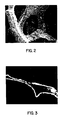
- FIG. 2 illustrates an irregular, bumpy, nodular deposit of nickel. These nodules of nickel and especially weaker points connecting the nodules, are suspected to create areas of inefficient electrical conductivity which increase the internal resistance of the battery plaque.
- Figure 3 illustrates actual discontinuities or holes within the nickel conductor wire of the nickel foam. These holes and especially weak points connecting the nodules, are also suspected of causing inefficient conductivity in battery plaques. Additionally, it is believed that this irregular shape of the electrochemical deposit contributes to mechanical weakness of the nickel foam.
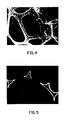
- Figures 4 and 5 illustrate a continuous smooth uniform deposit without any visible holes.
- the nickel carbonyl deposit of the invention has been proven to have unexpectedly improved qualities.
- the nickel carbonyl deposited nickel foam has both improved conductivity and improved mechanical properties. This improved conductivity and improved mechanical properties should facilitate a significant improvement in battery performance by lowering internal battery resistance, and increasing the amount of active mass a plaque will hold in a battery without mechanical failure.
- a carbon monoxide supply 10 feeds carbon monoxide gas to nickel carbonyl (Ni(CO)4) supply autoclave 12.
- Ni(CO)4 gas in nickel carbonyl supply autoclave is maintained at a desired temperature from about 10°C to about 38°C.
- Feed gas concentration resulting from pick-up of nickel carbonyl in carbon monoxide ranges from about 20 to about 90 percent nickel carbonyl by volume and from about 10 to about 80 percent carbon monoxide by volume.
- Ni(CO)4 gas from autoclave 12 enters the coating chamber 14.
- H2S gas or another catalyst may be added to the coating chamber 14 to promote nickel plating.
- the coating chamber 14 is supplied with continuous strips of foam 15.
- the foam 15 utilized may be any reticulated or open-pore foam.
- the reticulated foam may be polyurethane, polystyrene, polyvinylchloride, polyethelene, polyisocyanurates, polyphenols or polypropylene.
- reticulated polyurethane foam is supplied to the coating chamber.
- Polyurethane has proven effective despite having a melting temperature only slightly higher than the decomposition temperature of nickel carbonyl.
- Polyvinylchloride foam would be the least desirable, because of problems of treating exhaust gases formed during the sintering step.
- the chamber 14 is horizontally mounted, having two windows 16 and 18 constructed of Teflon® polymer, Pyrex® glass or quartz.
- the windows 16 and 18 form essentially infrared radiation transparent windows for allowing radiation to enter the coating chamber 14 from infrared sources 20 and 22 having parabolic reflector.
- the infrared radiation penetrates the windows 16 and 18 to selectively heat the foam 15 to a temperature at which nickel carbonyl decomposes without heating the chamber or gases inside the chamber to a temperature at which Ni(CO)4 decomposes.
- the nickel carbonyl decomposes on the foam 15 to form a substantially uniform deposit.
- Other alternative means for heating the foam 15 include induction heating and resistance heating of foams having or treated to have at least partial electrical conductivity.
- Polyurethane foam has infrared absorption peaks between 3.0 and 3.7 ⁇ m with a very strong absorption at 5.7 ⁇ m.
- Nickel carbonyl has a strong absorption between 4.8 and 4.9 ⁇ m and carbon monoxide has a strong absorption between 4.5 and 4.8 ⁇ m.
- This closeness in absorption peaks can cause problems in selectively heating foam in coating chamber 14.
- the problem is spontaneous decomposition of the Ni(CO)4 in chamber 14 without plating nickel on the foam 15 to form nickel plated foam 23.
- Heating potential of radiators 20 and 22 is controlled by a variable voltage regulator when radiators 20 and 22 are electrically powered. The voltage is adjusted to a voltage at which the radiators emit most energy at wavelengths below 2.5 ⁇ m.
- the radiation When polyurethane foam is used, the radiation must also not overheat the polyurethane. Intensity of infrared radiators 20 and 22 at the windows 16 and 18 has been about 1 watt per square centimeter. If the polyurethane is overheated it will decompose in the coating chamber 14. Wavelengths below 2.5 ⁇ m also effectively heat th nickel plated foam 23, since the nickel continues to decompose onto the nickel of nickel plated foam 23 without any significant decrease in decomposition rate. If available, use can be made of radiation filters external of chamber 14 which selectively absorb radiation of 4.5 to 4.9 ⁇ m wavelength.
- Polyurethane foam is first coated with a material for absorption of infrared radiation that is weakly absorbed by nickel carbonyl and carbon monoxide, such as carbon black, before it enters the coating chamber 14.
- a material for absorption of infrared radiation that is weakly absorbed by nickel carbonyl and carbon monoxide, such as carbon black
- pigments maybe incorporated directly into the foam itself to promote absorption of infrared radiation.
- Grey colored polyurethane foam has been successfully coated, however if the foam is too light in color, the foam is not effectively heated with infrared sources 20 and 22.
- Infrared sources 20 and 22 then supply infrared radiation with wavelengths primarily below 2.5 ⁇ m.
- the infrared radiation is supplied at wavelengths primarily below 2.0 ⁇ m. This range of wavelengths effectively heats the foam 15 without causing any spontaneous decomposition of the nickel carbonyl gas.
- Nickel carbonyl decomposes uniformly on the carbon black coated foam 15 plating first from the center of the foam 15.
- Coating chamber 14 is horizontally mounted. There is a Ni(CO)4 concentration gradient in the coating chamber 14. For this reason, the top and bottom infrared sources 20 and 22 may be adjusted to different settings to correct for any Ni(CO)4 concentration gradients by heating one side of foam 15 slightly hotter than the other. Also, it is important to avoid any uneven gas flow patterns of concentrated nickel carbonyl. These uneven gas flow patterns will also tend to deposit heavier in some areas.
- the coating chamber 14 may be positioned vertically. Vertical mounting of coating chamber 14 should facilitate a more uniform gas distribution on both sides of the foam 15.
- the nickel plated foam 23 is then transported to the furnace 24.
- Furnace 24 may be either openly connected to combustion chamber 14 for continuous operations, as illustrated, or be separately attached for batch-type operations.
- the furnace 24 is maintained in a reducing condition with hydrogen gas.
- the furnace 24 may be of any known type such as resistance, induction, or any suitable externally heated, fuel-type furnaces.
- Furnace 24 is supplied with a reducing gas 26 such as hydrogen gas to prevent oxidation of nickel foam 27.
- the nickel plated foam 17 is heated to a temperature between 850°C and 900°C in furnace 24.
- the polyurethane decomposes, leaving a reticulated network of substantially hollow nickel wires or nickel foam 27.
- the gases resulting from evaporation of the polyurethane foam escape from the network of wire.
- a portion of the foam 15 may remain within the nickel foam 27. However, it is preferred that the foam 15 is completely removed.
- the gases are believed to escape through small, unseen holes in the network or perhaps the gases escape partially by diffusion.
- foam 15 is plated using H2S gas catalyst, sulfur deposited in the nickel during this step is effectively removed from the nickel foam 27 in the furnace 24.
- Nickel foam 27 may shrink during annealing, however, nickel foam 27 having a porosity less than 96 percent does not shrink appreciably when heated at 850°C.
- the nickel foam 27 at temperatures between 850°C and 900°C anneals greatly improving the mechanical properties of nickel foam 27.
- nickel foam 27 may be rolled on a collection spool 28. Nickel foam 27 from the collection spool 28 may be rolled to desired thickness and cut to size for forming battery plaques. If desired, nickel foam 27 may be first annealed under oxidizing conditions and then under reducing conditions. This sequence may be necessary when using a more stable polymeric substrate.
- Tension between collection spool 28 and supply spool 29 may be used to stretch cells of foam 15.
- Collection spool 28 is pulled at a constant rate by a direct current motor (Experimental rates have pulled foam 15 at rates between 50 and 100 cm/hr).
- Nickel foam 27 formed from stretched foam 15 will have elongated cells and tend to have anisotropic properties. These anisotropic properties may be used to increase strength or conductivity in a preferred direction.
- exhaust gases from the coating chamber 14 travel first to a condenser autoclave 30 maintained by dry ice at -80°C to condense and freeze nickel carbonyl. Exhaust gases then pass on to a high temperature secondary decomposer 32 maintained at 280°C to further remove remaining Ni(CO)4. Exhaust gases from the secondary decomposer 32 are then burned with burner 34 to insure complete removal of the Ni(CO)4. Also, nitrogen from nitrogen supply 36 is supplied at a positive pressure to the entrance of foam 15 and exit of nickel foam 27 to insure Ni(CO)4 does not leak from the system. A nitrogen gas purge is also connected to the furnace exit to prevent the escape of hydrogen gas. Exhaust gases from the furnace are released through exit 38.
- Cell size of the battery plaque is controlled initially by the cell size of the foam.
- a foam of greater cell size than the final cell is required to compensate for shrinkage during heating of the foam and annealing of the nickel foam.
- the average distance across open-pore cells of the battery plaque is between 400 ⁇ m and 20 ⁇ m. Most preferentially, the average distance across the open-pore cell is between 100 ⁇ m and 60 ⁇ m.
- the smaller cell size increases surface area of the battery plaque and decreases the distance that electrons travel between the active mass and the battery plaque, but allows nickel hydroxide to be pushed freely into the plaque. If the size of the cells decreases substantially more, it could be difficult to squeeze nickel hydroxide particles into the plaque since the size of nickel hydroxide particles is typically on the order of about 10 ⁇ m.
- a battery plaque having a cell size between 400 and 20 ⁇ m may be created by either plating a compressed foam having a very small cell size or by simply rolling a nickel foam of larger size to reduce the cell size.
- the preferred method of producing the cells is to directly coat foam having a small cell size such as compressed polyurethane foam.
- the rolling of nickel foam is a simple way to decrease cell size, however, in rolling nickel foam, cell size is decreased at the expense of porosity. Additionally, rolling of battery plaques will not deform in a completely uniform manner causing disparities in the shape and size of cells across the plaque.
- the process of the invention avoids the need to roll nickel foam to decrease cell size.
- Cell size of the battery plaque is controlled initially by the cell size of the foam.
- a foam of greater cell size than the final cell is required to compensate for shrinkage during heating of the foam.
- Table 1 below provides a summary of conductivity comparing electrochemical nickel foams to nickel foams of the invention of various porosities.
- the conductivity of the nickel foam of the invention as a function of porosity was substantially greater than the electrochemically deposited CELMET® product of Sumitomo (Samples 14-18).
- the data from Table 1 are illustrated in Figure 7, where the electrochemical nickel foam has a significantly lower conductivity than nickel foam of the invention at a similar porosity. This increased performance satisfied the conductivity of a model having one third of its wires conducting in the x, y and z directions, unlike nickel foam formed from electrochemically deposited foam.
- the factor of 4 for CELMETTM was determined by the experimented data of TABLE 1 and the factor of 4 for METAPORETM was published in S. Langlois and F. Coeuret, Flow-through and flow-by porous electrodes of nickel foam. I. Material characterization. , 19 Journal of Applied Electrochemistry 43, 43-50 (1989).
- Increasing conductivity of the nickel foam of the invention lowers the internal resistance of the battery plaque. The lower resistance contributes to allowing quicker recharging rates and lowering battery overheating during recharging
- the tensile strength of nickel foam of the invention also was superior to that of electrochemically produced nickel foam.
- a die was used to cut samples of nickel foam to standard dimensions. The samples were dumbell shaped, having a total length of 11 cm (8 cm between clamps) and a variable thickness which varied with the samples. The samples were 1 cm wide in the neck (4.6 cm in length) and tapered at each end over a length of 1.6 cm to 2.0 cm in width. This standardized sample was a modification of ASTM D 412-83 Die C used for rubber testing. This standard was modified by increasing the width at the neck of the sample to 1.0 cm.
- Sample numbers 1-12 correspond to nickel foam produced by the process of the invention.
- Sample numbers 12 and 13 correspond to electrochemically produced CELMETTM nickel foams. Referring to Figure 8, a graph of Table 2, it is readily apparent that nickel foam of the TABLE 2 ULTIMATE TENSILE STRENGTH Sample Number Pores per Linear (cm) Thickness (cm) Mass (g) Porosity (%) Density (g/cm3) Fracture Strength (N) Initial Apparent Cross Section (mm2) Stress at Fracture (N/cm2) Stress at Fracture (MPa) 1 31.5 0.5 0.2534 96.538 0.308 13.13 5 262.6 2.63 2 23.6 1.1 0.6253 96.117 0.346 28.67 11 260.6 2.61 3 23.6 1.05 0.4759 96.904 0.276 14.03 10.5 133.6 1.34 4 23.6 1.2 0.4668 97.343 0.236 14.92 12 124.3 1.24 5 23.6 1.35 0.5461 97.237 0.246 22.27 13.5 165.0 1.
- Nickel foam from electrochemical nickel foam had an ultimate tensile strength of 1.754 MPa with a porosity of about 95.5 percent.
- the ultimate tensile strength of pure nickel bars is about 317 MPa.
- sample from the method of the invention had similar strengths with porosities as high as nearly 98 percent. This increase in mechanical properties allows a higher amount of active mass to be reliably held by the battery plaque having the same strength as the electrochemical nickel foam.
- the tensile strength of nickel foam of the invention corrected for porosity and multiplied by a factor between 4 and 6 was equal to or greater than 317 MPa.
- the tensile strength of nickel foam invention appears to be characterized by a factor of about 5.
- the method of the invention provides an extremely flexible method of producing nickel foam having significantly improved properties for use as battery plaques.
- the invention has produced nickel foams with porosities as high as 99 percent.
- the method of the invention also facilitates the production of nickel of increased thickness, such as foams 10 cm thick or more.
- the invention has the ability to produce foams having pore sizes as low as 20 ⁇ m.
- conductivity and tensile strength also are greatly improved with the invention.
- the nickel foam of the invention provides the above advantages over electrochemical nickel foam. These advantages indicate that nickel foam of the invention should significantly improve both battery plaque and battery performance.
- the nickel foam of the invention may also be used for other applications, such as high temperature filters.
Abstract
Description
- The invention relates to the field of nickel foams. More particularly, the invention relates to nickel foam battery plaques having improved conductivity, porosity, foam cell size, capacity to hold active mass, strength and a method for producing the improved battery plaques.
- Battery plaques have conventionally been formed by sintering nickel powder onto a nickel coated steel plate. Porosities achieved in the sintered plaque have been generally limited to porosities in the 80% range. These 80% range porosities, in turn, limit the amount of active mass that may be held in the plaque which limits the battery capacity. Low porosity and decreased capacity for holding active mass has long been a problem limiting the battery performance.
- Nickel plaques having increased porosity for batteries have been experimentally formed by chemical vapor deposition of nickel carbonyl on carbon felt. The battery plaques were formed by depositing nickel onto a carbon felt substrate and using the nickel coated felt substrate to support active mass. There are several problems with the carbon felt process. First, carbon felt is relatively expensive for the manufacture of batteries; second, the cell size of felt structures varies widely within the felt itself and is difficult to control for fibrous, felt-type structures; third, the carbon felt substrate remains in the battery; and fourth, the process was not satisfactory for polymer coated felts. Previous experimental attempts at chemical vapor deposition of polymer fibers for batteries produced a product having an inferior nickel coating having inferior mechanical stability which was unsuitable for battery plaques.
- Recently, in an attempt to overcome the low porosity problem, nickel battery plaques have been produced by an alternative electrochemical method (Matsamoto U.S. Pat. No. 4,251,603). Nickel is electroplated onto a polyurethane foam and sintered to form nickel foam. Before plating may be conducted, polyurethane foam is made conductive by immersion of the foam into a colloidal graphite dispersion and drying the foam. This nickel foam has increased porosity for increasing the amount of active mass battery plaques can support.
- Nickel foam, formed by electrochemical technique, has been produced by Sumitomo Electric Industries under the name CELMET™ and by SORAPEC under the name METAPORE™. The CELMET™ nickel foam has a highly irregular surface when magnified about 100 times. The electrical conductivity of the electrodeposited nickel foam is lower than the expected conductivity as a function of porosity due to the intrinsic structure of the electroplated nickel layer. The poorer conductivity effects battery output, recharging rates and battery overheating during recharging.
- Additionally, electrochemically plated nickel foam had less than ideal mechanical properties at high porosities. These lower mechanical properties at higher porosities limit the amount of active mass that may be reliably used in a battery without premature battery failure. A battery plaque formed with electrochemical nickel foam having too high a porosity would cause the plaque to have weak mechanical properties.
- It is an object of this invention to produce a nickel foam having improved conductivity.
- It is a further object of this invention to produce a nickel foam having improved mechanical properties at higher porosity levels.
- It is a further object of this invention to produce a nickel foam having a smaller pore size and more uniform structure for improved battery performance.
- It is a further object of this invention to provide an effective method of forming nickel foams with the above improved properties.
- The invention provides a method of forming nickel foam. An open-cell foam structure of thermally decomposable material is placed in an atmosphere containing nickel carbonyl gas. The foam structure is heated to a temperature at which the nickel carbonyl gas decomposes. Nickel from the nickel carbonyl gas is decomposed on the foam structure to form a nickel plated foam structure. The nickel plated foam structure is then sintered to remove the foam structure from the nickel plated foam structure leaving an isotropic, open-cell network of interconnected nickel wires to form the nickel foam.
- In addition, the invention provides a battery plaque of interconnected open-pore cells. The open-pore cells are comprised of substantially hollow nickel wires having a substantially uniform cross-section. Conductivity through the nickel structure is characterized by actual conductivity across the reticulated nickel network multiplied by a factor of 3.4 being about equal to or greater than the theoretical conductivity of nickel.
-
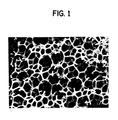
- Figure 1 is a scanning electron microscope (SEM) photomicrograph of a transverse cross-section of a nickel carbonyl plated foam magnified 30 times;
- Figure 2 is a SEM photomicrograph of the cell structure of electrochemically deposited nickel foam at 150 times magnification;
- Figure 3 is a SEM photomicrograph of a cross-section of electrochemically deposited nickel foam at 150 times magnification;
- Figure 4 is a SEM photomicrograph of the cell structure of nickel carbonyl deposited nickel foam at 150 times magnification;
- Figure 5 is a SEM photomicrograph of a cross-section of nickel carbonyl deposited nickel foam at 150 times magnification;
- Figure 6 is a schematic drawing of an apparatus for producing nickel foam by decomposing nickel carbonyl onto foam and sintering the coated foam;
- Figure 7 is a graph of conductivity versus porosity for electrochemically plated nickel foam and the nickel foam of the invention; and
- Figure 8 is a graph of ultimate tensile strength versus porosity for electrochemically plated nickel foam and the nickel foam of the invention.
- Referring to Figure 1, the reticulated open-cell structure of the invention is continuous and uniform. The uniform structure is a result of decomposition of nickel carbonyl vapor onto a reticulated or open-cell foam. The nickel coated foam is then sintered to "burn off" the enclosed foam, leaving an isotropic network of open nickel cells known as nickel foam. It has been discovered that battery plaques formed by the method of the invention have superior properties over battery plaques formed by sintering and electrochemical techniques. Theoretically, energy requirements for nickel foam produced by chemical vapor deposition are less than the energy requirements for electrochemical deposition of nickel.
- Improvements of the invention are dramatically illustrated by comparing electrochemically deposited nickel foam of Figures 2 and 3 to nickel foam of the invention of Figures 4 and 5. Figure 2 illustrates an irregular, bumpy, nodular deposit of nickel. These nodules of nickel and especially weaker points connecting the nodules, are suspected to create areas of inefficient electrical conductivity which increase the internal resistance of the battery plaque. Additionally, Figure 3 illustrates actual discontinuities or holes within the nickel conductor wire of the nickel foam. These holes and especially weak points connecting the nodules, are also suspected of causing inefficient conductivity in battery plaques. Additionally, it is believed that this irregular shape of the electrochemical deposit contributes to mechanical weakness of the nickel foam. By contrast, Figures 4 and 5 illustrate a continuous smooth uniform deposit without any visible holes. The nickel carbonyl deposit of the invention has been proven to have unexpectedly improved qualities. The nickel carbonyl deposited nickel foam has both improved conductivity and improved mechanical properties. This improved conductivity and improved mechanical properties should facilitate a significant improvement in battery performance by lowering internal battery resistance, and increasing the amount of active mass a plaque will hold in a battery without mechanical failure.
- Referring to Figure 6, the apparatus set up for coating foam with nickel carbonyl initially appears to be fairly simple. A carbon monoxide supply 10 feeds carbon monoxide gas to nickel carbonyl (Ni(CO)₄)
supply autoclave 12. Ni(CO)₄ gas in nickel carbonyl supply autoclave is maintained at a desired temperature from about 10°C to about 38°C. Feed gas concentration resulting from pick-up of nickel carbonyl in carbon monoxide ranges from about 20 to about 90 percent nickel carbonyl by volume and from about 10 to about 80 percent carbon monoxide by volume. Ni(CO)₄ gas fromautoclave 12 enters the coating chamber 14. Optionally, H₂S gas or another catalyst may be added to the coating chamber 14 to promote nickel plating. - The coating chamber 14 is supplied with continuous strips of
foam 15. Thefoam 15 utilized may be any reticulated or open-pore foam. The reticulated foam may be polyurethane, polystyrene, polyvinylchloride, polyethelene, polyisocyanurates, polyphenols or polypropylene. Preferably, reticulated polyurethane foam is supplied to the coating chamber. Polyurethane has proven effective despite having a melting temperature only slightly higher than the decomposition temperature of nickel carbonyl. Polyvinylchloride foam would be the least desirable, because of problems of treating exhaust gases formed during the sintering step. - The chamber 14 is horizontally mounted, having two
windows 16 and 18 constructed of Teflon® polymer, Pyrex® glass or quartz. Thewindows 16 and 18 form essentially infrared radiation transparent windows for allowing radiation to enter the coating chamber 14 frominfrared sources windows 16 and 18 to selectively heat thefoam 15 to a temperature at which nickel carbonyl decomposes without heating the chamber or gases inside the chamber to a temperature at which Ni(CO)₄ decomposes. The nickel carbonyl decomposes on thefoam 15 to form a substantially uniform deposit. Other alternative means for heating thefoam 15 include induction heating and resistance heating of foams having or treated to have at least partial electrical conductivity. - Polyurethane foam has infrared absorption peaks between 3.0 and 3.7 µm with a very strong absorption at 5.7 µm. Nickel carbonyl has a strong absorption between 4.8 and 4.9 µm and carbon monoxide has a strong absorption between 4.5 and 4.8 µm. This closeness in absorption peaks can cause problems in selectively heating foam in coating chamber 14. The problem is spontaneous decomposition of the Ni(CO)₄ in chamber 14 without plating nickel on the
foam 15 to form nickel platedfoam 23. Heating potential ofradiators radiators infrared radiators windows 16 and 18 has been about 1 watt per square centimeter. If the polyurethane is overheated it will decompose in the coating chamber 14. Wavelengths below 2.5 µm also effectively heat th nickel platedfoam 23, since the nickel continues to decompose onto the nickel of nickel platedfoam 23 without any significant decrease in decomposition rate. If available, use can be made of radiation filters external of chamber 14 which selectively absorb radiation of 4.5 to 4.9 µm wavelength. - Polyurethane foam is first coated with a material for absorption of infrared radiation that is weakly absorbed by nickel carbonyl and carbon monoxide, such as carbon black, before it enters the coating chamber 14. Alternatively, pigments maybe incorporated directly into the foam itself to promote absorption of infrared radiation. Grey colored polyurethane foam has been successfully coated, however if the foam is too light in color, the foam is not effectively heated with
infrared sources Infrared sources foam 15 without causing any spontaneous decomposition of the nickel carbonyl gas. Nickel carbonyl decomposes uniformly on the carbon black coatedfoam 15 plating first from the center of thefoam 15. Coating chamber 14 is horizontally mounted. There is a Ni(CO)₄ concentration gradient in the coating chamber 14. For this reason, the top and bottominfrared sources foam 15 slightly hotter than the other. Also, it is important to avoid any uneven gas flow patterns of concentrated nickel carbonyl. These uneven gas flow patterns will also tend to deposit heavier in some areas. Alternatively, the coating chamber 14 may be positioned vertically. Vertical mounting of coating chamber 14 should facilitate a more uniform gas distribution on both sides of thefoam 15. - The nickel plated
foam 23 is then transported to the furnace 24. Furnace 24 may be either openly connected to combustion chamber 14 for continuous operations, as illustrated, or be separately attached for batch-type operations. The furnace 24 is maintained in a reducing condition with hydrogen gas. The furnace 24 may be of any known type such as resistance, induction, or any suitable externally heated, fuel-type furnaces. Furnace 24 is supplied with a reducinggas 26 such as hydrogen gas to prevent oxidation ofnickel foam 27. The nickel plated foam 17 is heated to a temperature between 850°C and 900°C in furnace 24. The polyurethane decomposes, leaving a reticulated network of substantially hollow nickel wires ornickel foam 27. The gases resulting from evaporation of the polyurethane foam escape from the network of wire. A portion of thefoam 15 may remain within thenickel foam 27. However, it is preferred that thefoam 15 is completely removed. The gases are believed to escape through small, unseen holes in the network or perhaps the gases escape partially by diffusion. Whenfoam 15 is plated using H₂S gas catalyst, sulfur deposited in the nickel during this step is effectively removed from thenickel foam 27 in the furnace 24.Nickel foam 27 may shrink during annealing, however,nickel foam 27 having a porosity less than 96 percent does not shrink appreciably when heated at 850°C. In addition, thenickel foam 27 at temperatures between 850°C and 900°C anneals, greatly improving the mechanical properties ofnickel foam 27. After annealing,nickel foam 27 may be rolled on acollection spool 28.Nickel foam 27 from thecollection spool 28 may be rolled to desired thickness and cut to size for forming battery plaques. If desired,nickel foam 27 may be first annealed under oxidizing conditions and then under reducing conditions. This sequence may be necessary when using a more stable polymeric substrate. - Tension between
collection spool 28 andsupply spool 29 may be used to stretch cells offoam 15.Collection spool 28 is pulled at a constant rate by a direct current motor (Experimental rates have pulledfoam 15 at rates between 50 and 100 cm/hr).Nickel foam 27 formed from stretchedfoam 15 will have elongated cells and tend to have anisotropic properties. These anisotropic properties may be used to increase strength or conductivity in a preferred direction. - In the illustrated configuration of the invention, exhaust gases from the coating chamber 14 travel first to a
condenser autoclave 30 maintained by dry ice at -80°C to condense and freeze nickel carbonyl. Exhaust gases then pass on to a high temperaturesecondary decomposer 32 maintained at 280°C to further remove remaining Ni(CO)₄. Exhaust gases from thesecondary decomposer 32 are then burned withburner 34 to insure complete removal of the Ni(CO)₄. Also, nitrogen fromnitrogen supply 36 is supplied at a positive pressure to the entrance offoam 15 and exit ofnickel foam 27 to insure Ni(CO)₄ does not leak from the system. A nitrogen gas purge is also connected to the furnace exit to prevent the escape of hydrogen gas. Exhaust gases from the furnace are released throughexit 38. - Cell size of the battery plaque is controlled initially by the cell size of the foam. A foam of greater cell size than the final cell is required to compensate for shrinkage during heating of the foam and annealing of the nickel foam. Preferentially, the average distance across open-pore cells of the battery plaque is between 400 µm and 20 µm. Most preferentially, the average distance across the open-pore cell is between 100 µm and 60 µm. The smaller cell size increases surface area of the battery plaque and decreases the distance that electrons travel between the active mass and the battery plaque, but allows nickel hydroxide to be pushed freely into the plaque. If the size of the cells decreases substantially more, it could be difficult to squeeze nickel hydroxide particles into the plaque since the size of nickel hydroxide particles is typically on the order of about 10µm.
- A battery plaque having a cell size between 400 and 20 µm may be created by either plating a compressed foam having a very small cell size or by simply rolling a nickel foam of larger size to reduce the cell size. The preferred method of producing the cells is to directly coat foam having a small cell size such as compressed polyurethane foam. The rolling of nickel foam is a simple way to decrease cell size, however, in rolling nickel foam, cell size is decreased at the expense of porosity. Additionally, rolling of battery plaques will not deform in a completely uniform manner causing disparities in the shape and size of cells across the plaque. The process of the invention avoids the need to roll nickel foam to decrease cell size.
- To test conductivity of the samples, copper clamps were attached to opposing ends of rectangular nickel foam samples. Conductivity along the length of the foam was calculated by the formula:
σf =
where σf = Nickel foam conductivity
V = measured voltage in volts
w = sample width in cm
t = sample thickness in cm
1 = distance between probes
I = current in amperes - Cell size of the battery plaque is controlled initially by the cell size of the foam. A foam of greater cell size than the final cell is required to compensate for shrinkage during heating of the foam. Table 1 below provides a summary of conductivity comparing electrochemical nickel foams to nickel foams of the invention of various porosities.
- The conductivity of the nickel foam of the invention as a function of porosity (Samples 1-13) was substantially greater than the electrochemically deposited CELMET® product of Sumitomo (Samples 14-18). The data from Table 1 are illustrated in Figure 7, where the electrochemical nickel foam has a significantly lower conductivity than nickel foam of the invention at a similar porosity. This increased performance satisfied the conductivity of a model having one third of its wires conducting in the x, y and z directions, unlike nickel foam formed from electrochemically deposited foam. Conductivity of the nickel foam of the invention was found to the equation:

σf = apparent conductivity of nickel foam
P = porosity of nickel foam - This relationship is satisfied by the nickel foam produced by the method of this invention. In calculation of theoretical conductivity of nickel foam of the invention, the accepted value of 1.46 X 10⁵ ohm⁻¹ cm⁻¹ was used for σNi (CRC Hand book of Chemistry and Physics 68 th Edition). A factor of 3.4 multiplied by the theoretical conductivity and corrected for porosity satisfies the experimental data of the nickel foam of the invention. A factor of 3.2 satisfies most nickel foams of the invention. The plotted factor of 3 appears to effectively predict the relationship between porosity and conductivity for the nickel foam of the invention. However,
TABLE 1 NICKEL FOAM CONDUCTIVITY Sample Number Length (cm) Width (cm) Thickness (cm) Mass (g) Density (g/cm²) Porosity (%) Conductivity (1/Ohm-cm) Theoretical 1/3 Conductivity (1/Ohm-cm) 1 5 1 0.15 0.5055 0.481 94.59 2528.2 2636.1 2 5 1 0.15 0.1723 0.177 98.01 898.0 967.6 3 5 1 0.15 0.4112 0.397 95.54 2352.4 2175.4 4 5 1 0.15 0.1471 0.140 98.43 756.1 767.1 5 5 1 0.15 0.2863 0.252 97.16 1394.4 1382.4 6 5 1.15 0.15 0.1445 0.129 98.55 856.0 705.7 7 5 1 0.15 0.2597 0.247 97.22 1265.7 1354.3 8 5 1 0.19 0.1498 0.149 98.33 730.7 814.5 9 5 1.05 0.17 0.2816 0.222 97.50 1328.5 1216.7 10 5 1 0.08 0.2621 0.468 94.74 2624.0 2562.8 11 1.6 1.45 0.145 0.1209 0.290 96.74 1593.1 1590.2 12 4.7 2.1 0.125 0.4473 0.339 96.19 1810.7 1855.0 13 4.7 2.05 0.145 0.5262 0.351 96.06 1726.5 1919.4 14 5 1 0.15 0.5072 0.483 94.57 2045.3 2645.0 15 5 1.1 0.16 0.503 0.403 95.48 1336.3 2204.1 16 5 1.08 0.16 0.48 0.408 95.41 1345.0 2236.8 17 4.7 2.18 0.16 0.7231 0.411 95.39 1686.9 2247.8 18 4.7 2.12 0.16 0.6951 0.408 95.42 1942.7 2230.8 - The tensile strength of nickel foam of the invention also was superior to that of electrochemically produced nickel foam. A die was used to cut samples of nickel foam to standard dimensions. The samples were dumbell shaped, having a total length of 11 cm (8 cm between clamps) and a variable thickness which varied with the samples. The samples were 1 cm wide in the neck (4.6 cm in length) and tapered at each end over a length of 1.6 cm to 2.0 cm in width. This standardized sample was a modification of ASTM D 412-83 Die C used for rubber testing. This standard was modified by increasing the width at the neck of the sample to 1.0 cm.
- The samples were pulled at a constant rate of 0.13 mm/sec until the sample fractured. Only samples in which the sample fractured in the neck region were accepted as being valid. The data for the tests was as follows:
- Sample numbers 1-12 correspond to nickel foam produced by the process of the invention.
Sample numbers 12 and 13 correspond to electrochemically produced CELMET™ nickel foams. Referring to Figure 8, a graph of Table 2, it is readily apparent that nickel foam of theTABLE 2 ULTIMATE TENSILE STRENGTH Sample Number Pores per Linear (cm) Thickness (cm) Mass (g) Porosity (%) Density (g/cm³) Fracture Strength (N) Initial Apparent Cross Section (mm²) Stress at Fracture (N/cm²) Stress at Fracture (MPa) 1 31.5 0.5 0.2534 96.538 0.308 13.13 5 262.6 2.63 2 23.6 1.1 0.6253 96.117 0.346 28.67 11 260.6 2.61 3 23.6 1.05 0.4759 96.904 0.276 14.03 10.5 133.6 1.34 4 23.6 1.2 0.4668 97.343 0.236 14.92 12 124.3 1.24 5 23.6 1.35 0.5461 97.237 0.246 22.27 13.5 165.0 1.65 6 23.6 1.2 0.3426 98.050 0.174 11.67 12 97.3 0.97 7 23.6 1.15 0.3659 97.827 0.193 13.2 11.5 114.8 1.15 8 31.5 1.9 0.6775 97.564 0.217 25.28 19 133.1 1.33 9 31.5 1.95 0.6982 97.554 0.218 28.2 19.5 144.6 1.45 10 31.5 1.95 0.6147 97.847 0.192 34.14 19.5 175.1 1.75 11 31.5 1.65 0.426 98.237 0.157 20.55 16.5 124.5 1.25 12 23.6 1.63 0.9436 95.499 0.401 27.9 16.3 171.2 1.71 13 23.6 1.6 0.949 95.388 0.410 28.55 16 178.4 1.78 - The method of the invention provides an extremely flexible method of producing nickel foam having significantly improved properties for use as battery plaques. The invention has produced nickel foams with porosities as high as 99 percent. The method of the invention also facilitates the production of nickel of increased thickness, such as
foams 10 cm thick or more. The invention has the ability to produce foams having pore sizes as low as 20µm. As shown in Figure 7 and 8, conductivity and tensile strength also are greatly improved with the invention. The nickel foam of the invention provides the above advantages over electrochemical nickel foam. These advantages indicate that nickel foam of the invention should significantly improve both battery plaque and battery performance. The nickel foam of the invention may also be used for other applications, such as high temperature filters. - Although the invention is illustrated and described herein with reference to specific embodiments, it is not limited to these embodiments. Those skilled in the art will understand that changes may be made in the form of the invention covered by the claims and that certain features of the invention may sometimes be used to advantage without a corresponding use of the other features.
Claims (17)
heating an open-cell thermally decomposable foam structure in an atmosphere containing nickel carbonyl gas to a temperature at which said nickel carbonyl gas decomposes, whereby nickel is decomposed from said nickel carbonyl gas on said foam structure to form a nickel-plated foam structure, and
sintering said nickel-plated foam structure to thermally decompose and remove said foam structure from said nickel-plated foam structure leaving an open-cell nickel network of interconnected nickel wires to form said nickel foam.
Applications Claiming Priority (2)
| Application Number | Priority Date | Filing Date | Title |
|---|---|---|---|
| US368193 | 1989-06-16 | ||
| US07/368,193 US4957543A (en) | 1989-06-16 | 1989-06-16 | Method of forming nickel foam |
Publications (3)
| Publication Number | Publication Date |
|---|---|
| EP0402738A2 true EP0402738A2 (en) | 1990-12-19 |
| EP0402738A3 EP0402738A3 (en) | 1993-03-17 |
| EP0402738B1 EP0402738B1 (en) | 1997-01-29 |
Family
ID=23450237
Family Applications (1)
| Application Number | Title | Priority Date | Filing Date |
|---|---|---|---|
| EP90110606A Expired - Lifetime EP0402738B1 (en) | 1989-06-16 | 1990-06-05 | Nickel foam |
Country Status (11)
| Country | Link |
|---|---|
| US (1) | US4957543A (en) |
| EP (1) | EP0402738B1 (en) |
| JP (1) | JPH0330259A (en) |
| AT (1) | ATE148506T1 (en) |
| AU (1) | AU619685B2 (en) |
| BR (1) | BR9002863A (en) |
| CA (1) | CA2019023C (en) |
| DE (1) | DE69029822T2 (en) |
| ES (1) | ES2097119T3 (en) |
| MX (1) | MX167115B (en) |
| ZA (1) | ZA904663B (en) |
Cited By (10)
| Publication number | Priority date | Publication date | Assignee | Title |
|---|---|---|---|---|
| FR2679927A1 (en) * | 1991-08-02 | 1993-02-05 | Sorapec | Production of metal foams |
| EP0603392A1 (en) * | 1992-05-13 | 1994-06-29 | Sumitomo Electric Industries, Ltd | Particulate trap for purifying diesel engine exhaust gas |
| US5584983A (en) * | 1992-02-26 | 1996-12-17 | Stork Screens, B.V. | Method for the production of a metal foam |
| WO1997006570A1 (en) * | 1995-08-04 | 1997-02-20 | Eltech Systems Corporation | Conductive metal porous sheet production |
| EP0790656A1 (en) * | 1996-02-15 | 1997-08-20 | Inco Limited | porous nickel electrode substrate |
| EP0803923A2 (en) * | 1996-04-24 | 1997-10-29 | Inco Limited | A method for varying the density of plated foam and a battery electrode comprising a plated porous metal substrate and sintered metal powder applied thereto |
| WO2000000453A2 (en) * | 1998-06-29 | 2000-01-06 | Sm Schweizerische Munitionsunternehmung Ag | Pyrotechnic layer for targeted data destruction on data carriers |
| EP1030392A2 (en) * | 1999-02-17 | 2000-08-23 | Matsushita Electric Industrial Co., Ltd. | Hydrogene storage alloy electrode and method for manufacturing the same |
| EP1059275A1 (en) * | 1999-06-07 | 2000-12-13 | SM Schweizerische Munitionsunternehmung | Pyrotechnic layer for targeted destruction of machine readable data on a data storage medium |
| CN106064241A (en) * | 2016-07-09 | 2016-11-02 | 大连理工大学 | A kind of preparation method of internal diameter controllable foam metal |
Families Citing this family (37)
| Publication number | Priority date | Publication date | Assignee | Title |
|---|---|---|---|---|
| DE69219000T2 (en) * | 1991-05-10 | 1997-07-24 | Japan Storage Battery Co Ltd | Prismatic gas-tight alkaline battery with a nickel hydroxide electrode |
| US5882822A (en) * | 1995-09-28 | 1999-03-16 | Shin-Etsu Chemical Co., Ltd. | Battery electrode and method for the preparation thereof |
| DE69625330T2 (en) * | 1995-10-17 | 2003-08-28 | Sanyo Electric Co | METHOD FOR PRODUCING AN ALKALINE BATTERY WITH A SPONGE-LIKE METAL SUBSTRATE |
| US5766683A (en) * | 1996-11-12 | 1998-06-16 | New American Tec | Nickel deposition system with a vapor recovery system |
| US5735977A (en) * | 1996-12-12 | 1998-04-07 | Inco Limited | Process for removal of polymer foams from nickel-coated substrates |
| US5951791A (en) * | 1997-12-01 | 1999-09-14 | Inco Limited | Method of preparing porous nickel-aluminum structures |
| US6118094A (en) * | 1999-01-28 | 2000-09-12 | Eveready Battery Company, Inc. | Arc deburring of electrochemical cell electrodes |
| JP4566303B2 (en) * | 1999-07-22 | 2010-10-20 | 本田技研工業株式会社 | Nickel metal hydride battery positive plate |
| DE10008257A1 (en) | 2000-02-23 | 2001-08-30 | Alstom Power Schweiz Ag Baden | Process for repairing a gas turbine component |
| CN2515794Y (en) | 2001-03-23 | 2002-10-09 | 东莞南光电器有限公司 | Flash lamp tube |
| US6660224B2 (en) | 2001-08-16 | 2003-12-09 | National Research Council Of Canada | Method of making open cell material |
| US7108828B2 (en) * | 2001-08-27 | 2006-09-19 | National Research Council Of Canada | Method of making open cell material |
| US7458991B2 (en) * | 2002-02-08 | 2008-12-02 | Howmedica Osteonics Corp. | Porous metallic scaffold for tissue ingrowth |
| US20070063368A1 (en) * | 2004-02-23 | 2007-03-22 | Nike, Inc. | Fluid-filled bladder incorporating a foam tensile member |
| US7393446B2 (en) * | 2004-03-05 | 2008-07-01 | Frank E. Towsley | Cellular metal structure |
| US20050221163A1 (en) * | 2004-04-06 | 2005-10-06 | Quanmin Yang | Nickel foam and felt-based anode for solid oxide fuel cells |
| US20070051636A1 (en) * | 2005-09-07 | 2007-03-08 | Inco Limited | Process for producing metal foams having uniform cell structure |
| US20070178988A1 (en) * | 2006-02-01 | 2007-08-02 | Nike, Inc. | Golf clubs and golf club heads including cellular structure metals and other materials |
| US7941941B2 (en) | 2007-07-13 | 2011-05-17 | Nike, Inc. | Article of footwear incorporating foam-filled elements and methods for manufacturing the foam-filled elements |
| US20090196821A1 (en) * | 2008-02-06 | 2009-08-06 | University Of Delaware | Plated cobalt-boron catalyst on high surface area templates for hydrogen generation from sodium borohydride |
| WO2009131700A2 (en) * | 2008-04-25 | 2009-10-29 | Envia Systems, Inc. | High energy lithium ion batteries with particular negative electrode compositions |
| US8389160B2 (en) * | 2008-10-07 | 2013-03-05 | Envia Systems, Inc. | Positive electrode materials for lithium ion batteries having a high specific discharge capacity and processes for the synthesis of these materials |
| US9012073B2 (en) * | 2008-11-11 | 2015-04-21 | Envia Systems, Inc. | Composite compositions, negative electrodes with composite compositions and corresponding batteries |
| US8465873B2 (en) | 2008-12-11 | 2013-06-18 | Envia Systems, Inc. | Positive electrode materials for high discharge capacity lithium ion batteries |
| US8329091B2 (en) * | 2009-01-30 | 2012-12-11 | Widener University | Porous metallic structures |
| EP2261398B1 (en) * | 2009-06-10 | 2018-12-05 | Universität des Saarlandes | Metal foams |
| US9843041B2 (en) * | 2009-11-11 | 2017-12-12 | Zenlabs Energy, Inc. | Coated positive electrode materials for lithium ion batteries |
| CN102735581B (en) * | 2012-07-19 | 2014-03-26 | 先进储能材料国家工程研究中心有限责任公司 | Device and method for lossless and continuous detection of density uniformity of belt-shaped material |
| US9863045B2 (en) | 2015-03-24 | 2018-01-09 | Council Of Scientific & Industrial Research | Electrochemical process for the preparation of lead foam |
| US10190211B2 (en) * | 2015-11-20 | 2019-01-29 | Fourté International, Sdn. Bhd | High conductivity graphane-metal and graphene-metal composite and methods of manufacture |
| US9945027B2 (en) | 2015-11-20 | 2018-04-17 | Fourté International, Sdn. Bhd. | High conductivity graphene-metal composite and methods of manufacture |
| US10501845B2 (en) | 2015-11-20 | 2019-12-10 | Fourté International, Sdn. Bhd | Thin metal coating methods for high conductivity graphane-metal composites and methods of manufacture |
| US10590529B2 (en) | 2015-11-20 | 2020-03-17 | Fourté International, Sdn. Bhd | Metal foams and methods of manufacture |
| US10544504B2 (en) | 2015-11-20 | 2020-01-28 | Fourte' International, Sdn. Bhd. | Thin metal coating methods for high conductivity graphene and stanene metal composites and methods of manufacture |
| KR102218854B1 (en) * | 2016-11-30 | 2021-02-23 | 주식회사 엘지화학 | Preparation method for metal foam |
| KR102166464B1 (en) * | 2016-11-30 | 2020-10-16 | 주식회사 엘지화학 | Preparation method for metal foam |
| WO2018098585A1 (en) | 2016-12-02 | 2018-06-07 | Polyvalor, Limited Partnership | Openly porous acoustic foam, process for manufacture and uses thereof |
Citations (12)
| Publication number | Priority date | Publication date | Assignee | Title |
|---|---|---|---|---|
| FR1067640A (en) * | 1951-12-14 | 1954-06-17 | Basf Ag | Electrode frames for accumulators |
| GB762670A (en) * | 1952-09-20 | 1956-12-05 | Caroline Elisabeth Stiftung | Improvements in or relating to the production of porous metal bodies |
| US3087233A (en) * | 1960-11-16 | 1963-04-30 | Fram Corp | Pervious metal fiber material and method of making the same |
| FR1374314A (en) * | 1961-05-05 | 1964-10-09 | Accumulateurs Fixes | Process for manufacturing fibers or similar articles, in particular of metal, of plastics, of asbestos, of glass with a nickel coating, and products resulting therefrom |
| FR2027985A1 (en) * | 1969-01-09 | 1970-10-02 | Dunlop Co Ltd | Porous structure for fuel cells and their - electrodes |
| US3843950A (en) * | 1971-07-07 | 1974-10-22 | Schladitz Whiskers Ag | Porous electric heating element |
| FR2232839A1 (en) * | 1973-06-07 | 1975-01-03 | Battelle Memorial Institute | |
| FR2232838A1 (en) * | 1973-06-07 | 1975-01-03 | Battelle Memorial Institute | |
| US4251603A (en) * | 1980-02-13 | 1981-02-17 | Matsushita Electric Industrial Co., Ltd. | Battery electrode |
| EP0151064A2 (en) * | 1984-01-25 | 1985-08-07 | SORAPEC Société de Recherche et d'Applications Electrochimiques | Porous metallic structure, its fabrication and applications |
| US4687702A (en) * | 1986-06-20 | 1987-08-18 | Chemtronics | Structural insulating panel and method of making the panel |
| DE3919570A1 (en) * | 1988-06-17 | 1989-12-21 | Vapor Technologies Inc | METHOD FOR PRODUCING STRUCTURAL BODIES WITH A LARGE SURFACE / VOLUME RATIO, AND STRUCTURED BODIES PRODUCED BY THIS METHOD |
Family Cites Families (16)
| Publication number | Priority date | Publication date | Assignee | Title |
|---|---|---|---|---|
| US2986115A (en) * | 1958-03-14 | 1961-05-30 | Union Carbide Corp | Gas plating of synthetic fibers |
| US3075494A (en) * | 1960-02-19 | 1963-01-29 | Union Carbide Corp | Apparatus for making metallized porous refractory material |
| US3111396A (en) * | 1960-12-14 | 1963-11-19 | Gen Electric | Method of making a porous material |
| US3160517A (en) * | 1961-11-13 | 1964-12-08 | Union Carbide Corp | Method of depositing metals and metallic compounds throughout the pores of a porous body |
| US3213827A (en) * | 1962-03-13 | 1965-10-26 | Union Carbide Corp | Apparatus for gas plating bulk material to metallize the same |
| DE2055927C3 (en) * | 1970-11-13 | 1978-04-20 | Schladitz-Whiskers Ag, Zug (Schweiz) | Porous, electrically conductive object, in particular an electrical heating element |
| US3900646A (en) * | 1973-02-21 | 1975-08-19 | Robert A Clyde | Method of plating metal uniformly on and throughout porous structures |
| JPS5834902A (en) * | 1981-08-26 | 1983-03-01 | Hitachi Ltd | Electromagnetic coil |
| EP0101681B1 (en) * | 1981-09-08 | 1994-12-14 | The Rockefeller University | Antibody to a mediator activity composition and its use in a pharmaceutical composition |
| US4443526A (en) * | 1982-03-03 | 1984-04-17 | Westinghouse Electric Corp. | NiCO3 Electrode material and electrode |
| JPS5953350A (en) * | 1982-09-17 | 1984-03-28 | Sharp Corp | Conveyor for the original and method of inverting the original |
| DE3623786A1 (en) * | 1985-11-13 | 1987-05-14 | Man Technologie Gmbh | METHOD FOR PRODUCING SOOT FILTERS |
| FR2626102B1 (en) * | 1988-01-19 | 1990-05-04 | Thomson Csf | LOAD TRANSFER MEMORY AND MANUFACTURING METHOD THEREOF |
| JPH028543A (en) * | 1988-06-28 | 1990-01-12 | Toyota Motor Corp | Falloff preventing device for oil pump driven gear |
| JPH063974A (en) * | 1992-06-24 | 1994-01-14 | Canon Inc | Image forming device |
| JP3304514B2 (en) * | 1993-06-16 | 2002-07-22 | 修 惣川 | Water heater |
-
1989
- 1989-06-16 US US07/368,193 patent/US4957543A/en not_active Expired - Lifetime
-
1990
- 1990-06-05 AT AT90110606T patent/ATE148506T1/en not_active IP Right Cessation
- 1990-06-05 DE DE69029822T patent/DE69029822T2/en not_active Expired - Lifetime
- 1990-06-05 ES ES90110606T patent/ES2097119T3/en not_active Expired - Lifetime
- 1990-06-05 EP EP90110606A patent/EP0402738B1/en not_active Expired - Lifetime
- 1990-06-14 CA CA002019023A patent/CA2019023C/en not_active Expired - Lifetime
- 1990-06-14 JP JP2156582A patent/JPH0330259A/en active Granted
- 1990-06-15 MX MX021182A patent/MX167115B/en unknown
- 1990-06-15 ZA ZA904663A patent/ZA904663B/en unknown
- 1990-06-15 AU AU57519/90A patent/AU619685B2/en not_active Ceased
- 1990-06-18 BR BR909002863A patent/BR9002863A/en not_active IP Right Cessation
Patent Citations (12)
| Publication number | Priority date | Publication date | Assignee | Title |
|---|---|---|---|---|
| FR1067640A (en) * | 1951-12-14 | 1954-06-17 | Basf Ag | Electrode frames for accumulators |
| GB762670A (en) * | 1952-09-20 | 1956-12-05 | Caroline Elisabeth Stiftung | Improvements in or relating to the production of porous metal bodies |
| US3087233A (en) * | 1960-11-16 | 1963-04-30 | Fram Corp | Pervious metal fiber material and method of making the same |
| FR1374314A (en) * | 1961-05-05 | 1964-10-09 | Accumulateurs Fixes | Process for manufacturing fibers or similar articles, in particular of metal, of plastics, of asbestos, of glass with a nickel coating, and products resulting therefrom |
| FR2027985A1 (en) * | 1969-01-09 | 1970-10-02 | Dunlop Co Ltd | Porous structure for fuel cells and their - electrodes |
| US3843950A (en) * | 1971-07-07 | 1974-10-22 | Schladitz Whiskers Ag | Porous electric heating element |
| FR2232839A1 (en) * | 1973-06-07 | 1975-01-03 | Battelle Memorial Institute | |
| FR2232838A1 (en) * | 1973-06-07 | 1975-01-03 | Battelle Memorial Institute | |
| US4251603A (en) * | 1980-02-13 | 1981-02-17 | Matsushita Electric Industrial Co., Ltd. | Battery electrode |
| EP0151064A2 (en) * | 1984-01-25 | 1985-08-07 | SORAPEC Société de Recherche et d'Applications Electrochimiques | Porous metallic structure, its fabrication and applications |
| US4687702A (en) * | 1986-06-20 | 1987-08-18 | Chemtronics | Structural insulating panel and method of making the panel |
| DE3919570A1 (en) * | 1988-06-17 | 1989-12-21 | Vapor Technologies Inc | METHOD FOR PRODUCING STRUCTURAL BODIES WITH A LARGE SURFACE / VOLUME RATIO, AND STRUCTURED BODIES PRODUCED BY THIS METHOD |
Cited By (18)
| Publication number | Priority date | Publication date | Assignee | Title |
|---|---|---|---|---|
| FR2679927A1 (en) * | 1991-08-02 | 1993-02-05 | Sorapec | Production of metal foams |
| US5584983A (en) * | 1992-02-26 | 1996-12-17 | Stork Screens, B.V. | Method for the production of a metal foam |
| EP0603392A1 (en) * | 1992-05-13 | 1994-06-29 | Sumitomo Electric Industries, Ltd | Particulate trap for purifying diesel engine exhaust gas |
| EP0603392A4 (en) * | 1992-05-13 | 1994-08-31 | Sumitomo Electric Industries, Ltd | |
| US5458664A (en) * | 1992-05-13 | 1995-10-17 | Sumitomo Electric Industries, Ltd. | Particulate trap for purifying diesel engine exhaust |
| WO1997006570A1 (en) * | 1995-08-04 | 1997-02-20 | Eltech Systems Corporation | Conductive metal porous sheet production |
| US5738907A (en) * | 1995-08-04 | 1998-04-14 | Eltech Systems Corporation | Conductive metal porous sheet production |
| US5700363A (en) * | 1996-02-15 | 1997-12-23 | Inco Limited | Porous nickel electrode substrate |
| EP0790656A1 (en) * | 1996-02-15 | 1997-08-20 | Inco Limited | porous nickel electrode substrate |
| EP0803923A2 (en) * | 1996-04-24 | 1997-10-29 | Inco Limited | A method for varying the density of plated foam and a battery electrode comprising a plated porous metal substrate and sintered metal powder applied thereto |
| EP0803923A3 (en) * | 1996-04-24 | 1998-01-28 | Inco Limited | A method for varying the density of plated foam and a battery electrode comprising a plated porous metal substrate and sintered metal powder applied thereto |
| US5839049A (en) * | 1996-04-24 | 1998-11-17 | Inco Limited | Method for varying the density of plated foam |
| WO2000000453A2 (en) * | 1998-06-29 | 2000-01-06 | Sm Schweizerische Munitionsunternehmung Ag | Pyrotechnic layer for targeted data destruction on data carriers |
| WO2000000453A3 (en) * | 1998-06-29 | 2000-03-16 | Eidgenoess Munitionsfab Thun | Pyrotechnic layer for targeted data destruction on data carriers |
| EP1030392A2 (en) * | 1999-02-17 | 2000-08-23 | Matsushita Electric Industrial Co., Ltd. | Hydrogene storage alloy electrode and method for manufacturing the same |
| EP1030392A3 (en) * | 1999-02-17 | 2002-07-31 | Matsushita Electric Industrial Co., Ltd. | Hydrogene storage alloy electrode and method for manufacturing the same |
| EP1059275A1 (en) * | 1999-06-07 | 2000-12-13 | SM Schweizerische Munitionsunternehmung | Pyrotechnic layer for targeted destruction of machine readable data on a data storage medium |
| CN106064241A (en) * | 2016-07-09 | 2016-11-02 | 大连理工大学 | A kind of preparation method of internal diameter controllable foam metal |
Also Published As
| Publication number | Publication date |
|---|---|
| EP0402738B1 (en) | 1997-01-29 |
| JPH0447430B2 (en) | 1992-08-03 |
| CA2019023C (en) | 1997-09-09 |
| US4957543A (en) | 1990-09-18 |
| ZA904663B (en) | 1991-04-24 |
| DE69029822D1 (en) | 1997-03-13 |
| DE69029822T2 (en) | 1997-08-28 |
| ES2097119T3 (en) | 1997-04-01 |
| AU5751990A (en) | 1990-12-20 |
| ATE148506T1 (en) | 1997-02-15 |
| MX167115B (en) | 1993-03-04 |
| BR9002863A (en) | 1991-08-20 |
| CA2019023A1 (en) | 1990-12-16 |
| JPH0330259A (en) | 1991-02-08 |
| EP0402738A3 (en) | 1993-03-17 |
| AU619685B2 (en) | 1992-01-30 |
Similar Documents
| Publication | Publication Date | Title |
|---|---|---|
| EP0402738B1 (en) | Nickel foam | |
| EP0184638B1 (en) | Process of producing a flexbile fuel cell electrode from a carbon paper | |
| CN1114963C (en) | Process for preparing metallic porous body, electrody substrate for battery and process for preparing the same | |
| KR100824844B1 (en) | Nickel foam and felt-based anode for solid oxide fuel cells | |
| DE69637082T2 (en) | Battery electrode substrate and method for its production | |
| Ho et al. | Structure influence on electrocatalysis and adsorption of intermediates in the anodic O2 evolution at dimorphic α-and β-PbO2 | |
| JPH08222241A (en) | Manufacture of graphite member for solid high polymer fuel cell | |
| CN1192290A (en) | Conductive metal porous sheet production | |
| JPH06140047A (en) | Manufacture of carbon carrier for phosphoric acid type fuel cell catalyst | |
| US4675094A (en) | Oxygen-cathode for use in electrolysis of alkali chloride and process for preparing the same | |
| JPWO2019049934A1 (en) | Gas diffusion layer base material for fuel cells, gas diffusion layer for fuel cells, fuel cells | |
| WO2014056114A1 (en) | Method of producing porous electrodes for batteries and fuel cells | |
| US4654195A (en) | Method for fabricating molten carbonate ribbed anodes | |
| US20050079403A1 (en) | Fuel cell gas diffusion layer | |
| Kaushal et al. | Upshot of natural graphite inclusion on the performance of porous conducting carbon fiber paper in a polymer electrolyte membrane fuel cell | |
| KR101612529B1 (en) | Pressurized crucible for preparing graphite | |
| EP0686718A1 (en) | Unwoven metal fabric and method of manufacturing the same | |
| DE4142712A1 (en) | Pressed and sintered electrodes for fuel cells - made from a mixt. of metal powder, ceramic powder and polymer powder rendered ion and electron conductive by ion beam treatment | |
| JPH11162795A (en) | Activated carbon powder, carbon body, carbon electrode electrode for electric double layer capacitor, and manufacture of the same | |
| KR101644096B1 (en) | Container for preparing graphite sheet | |
| KR100187430B1 (en) | Method of manufacturing electrolyte matrix for phosphorus fuel cell made of sic whisker | |
| Johnson et al. | High surface area, low-weight composite nickel fiber electrodes | |
| Ferrando | Fabrication of prototype large scale composite fiber nickel electrodes | |
| JP2011153384A (en) | Carbon fiber sheet, and method for producing the same | |
| KR20220127448A (en) | Method for manufacturing composite anode for lithium ion battery |
Legal Events
| Date | Code | Title | Description |
|---|---|---|---|
| PUAI | Public reference made under article 153(3) epc to a published international application that has entered the european phase |
Free format text: ORIGINAL CODE: 0009012 |
|
| AK | Designated contracting states |
Kind code of ref document: A2 Designated state(s): AT BE CH DE ES FR GB GR IT LI LU NL SE |
|
| PUAL | Search report despatched |
Free format text: ORIGINAL CODE: 0009013 |
|
| AK | Designated contracting states |
Kind code of ref document: A3 Designated state(s): AT BE CH DE ES FR GB GR IT LI LU NL SE |
|
| 17P | Request for examination filed |
Effective date: 19930908 |
|
| 17Q | First examination report despatched |
Effective date: 19950728 |
|
| RAP1 | Party data changed (applicant data changed or rights of an application transferred) |
Owner name: INCO LIMITED |
|
| GRAG | Despatch of communication of intention to grant |
Free format text: ORIGINAL CODE: EPIDOS AGRA |
|
| GRAH | Despatch of communication of intention to grant a patent |
Free format text: ORIGINAL CODE: EPIDOS IGRA |
|
| GRAH | Despatch of communication of intention to grant a patent |
Free format text: ORIGINAL CODE: EPIDOS IGRA |
|
| GRAA | (expected) grant |
Free format text: ORIGINAL CODE: 0009210 |
|
| AK | Designated contracting states |
Kind code of ref document: B1 Designated state(s): AT BE CH DE ES FR GB GR IT LI LU NL SE |
|
| PG25 | Lapsed in a contracting state [announced via postgrant information from national office to epo] |
Ref country code: CH Effective date: 19970129 Ref country code: GR Free format text: LAPSE BECAUSE OF FAILURE TO SUBMIT A TRANSLATION OF THE DESCRIPTION OR TO PAY THE FEE WITHIN THE PRESCRIBED TIME-LIMIT Effective date: 19970129 Ref country code: LI Effective date: 19970129 Ref country code: NL Free format text: LAPSE BECAUSE OF FAILURE TO SUBMIT A TRANSLATION OF THE DESCRIPTION OR TO PAY THE FEE WITHIN THE PRESCRIBED TIME-LIMIT Effective date: 19970129 Ref country code: BE Effective date: 19970129 Ref country code: AT Effective date: 19970129 |
|
| REF | Corresponds to: |
Ref document number: 148506 Country of ref document: AT Date of ref document: 19970215 Kind code of ref document: T |
|
| REG | Reference to a national code |
Ref country code: CH Ref legal event code: EP |
|
| REF | Corresponds to: |
Ref document number: 69029822 Country of ref document: DE Date of ref document: 19970313 |
|
| ITF | It: translation for a ep patent filed |
Owner name: 0403;03RMFSOCIETA' ITALIANA BREVETTI S.P |
|
| REG | Reference to a national code |
Ref country code: ES Ref legal event code: FG2A Ref document number: 2097119 Country of ref document: ES Kind code of ref document: T3 |
|
| ET | Fr: translation filed | ||
| PG25 | Lapsed in a contracting state [announced via postgrant information from national office to epo] |
Ref country code: LU Free format text: LAPSE BECAUSE OF NON-PAYMENT OF DUE FEES Effective date: 19970630 |
|
| NLV1 | Nl: lapsed or annulled due to failure to fulfill the requirements of art. 29p and 29m of the patents act | ||
| REG | Reference to a national code |
Ref country code: CH Ref legal event code: PL |
|
| PLBE | No opposition filed within time limit |
Free format text: ORIGINAL CODE: 0009261 |
|
| STAA | Information on the status of an ep patent application or granted ep patent |
Free format text: STATUS: NO OPPOSITION FILED WITHIN TIME LIMIT |
|
| 26N | No opposition filed | ||
| REG | Reference to a national code |
Ref country code: GB Ref legal event code: IF02 |
|
| PGFP | Annual fee paid to national office [announced via postgrant information from national office to epo] |
Ref country code: ES Payment date: 20090626 Year of fee payment: 20 |
|
| PGFP | Annual fee paid to national office [announced via postgrant information from national office to epo] |
Ref country code: FR Payment date: 20090617 Year of fee payment: 20 |
|
| PGFP | Annual fee paid to national office [announced via postgrant information from national office to epo] |
Ref country code: SE Payment date: 20090629 Year of fee payment: 20 Ref country code: DE Payment date: 20090629 Year of fee payment: 20 Ref country code: GB Payment date: 20090625 Year of fee payment: 20 |
|
| PGFP | Annual fee paid to national office [announced via postgrant information from national office to epo] |
Ref country code: IT Payment date: 20090629 Year of fee payment: 20 |
|
| REG | Reference to a national code |
Ref country code: GB Ref legal event code: PE20 Expiry date: 20100604 |
|
| EUG | Se: european patent has lapsed | ||
| REG | Reference to a national code |
Ref country code: ES Ref legal event code: FD2A Effective date: 20100607 |
|
| PG25 | Lapsed in a contracting state [announced via postgrant information from national office to epo] |
Ref country code: ES Free format text: LAPSE BECAUSE OF EXPIRATION OF PROTECTION Effective date: 20100607 |
|
| PG25 | Lapsed in a contracting state [announced via postgrant information from national office to epo] |
Ref country code: GB Free format text: LAPSE BECAUSE OF EXPIRATION OF PROTECTION Effective date: 20100604 |
|
| PG25 | Lapsed in a contracting state [announced via postgrant information from national office to epo] |
Ref country code: DE Free format text: LAPSE BECAUSE OF EXPIRATION OF PROTECTION Effective date: 20100605 |