EP0400476A2 - Laser machining device - Google Patents
Laser machining device Download PDFInfo
- Publication number
- EP0400476A2 EP0400476A2 EP90109821A EP90109821A EP0400476A2 EP 0400476 A2 EP0400476 A2 EP 0400476A2 EP 90109821 A EP90109821 A EP 90109821A EP 90109821 A EP90109821 A EP 90109821A EP 0400476 A2 EP0400476 A2 EP 0400476A2
- Authority
- EP
- European Patent Office
- Prior art keywords
- movement
- machining
- workpiece
- transport
- speed
- Prior art date
- Legal status (The legal status is an assumption and is not a legal conclusion. Google has not performed a legal analysis and makes no representation as to the accuracy of the status listed.)
- Granted
Links
Images

Classifications
-
- B—PERFORMING OPERATIONS; TRANSPORTING
- B23—MACHINE TOOLS; METAL-WORKING NOT OTHERWISE PROVIDED FOR
- B23K—SOLDERING OR UNSOLDERING; WELDING; CLADDING OR PLATING BY SOLDERING OR WELDING; CUTTING BY APPLYING HEAT LOCALLY, e.g. FLAME CUTTING; WORKING BY LASER BEAM
- B23K26/00—Working by laser beam, e.g. welding, cutting or boring
- B23K26/08—Devices involving relative movement between laser beam and workpiece
- B23K26/083—Devices involving movement of the workpiece in at least one axial direction
- B23K26/0838—Devices involving movement of the workpiece in at least one axial direction by using an endless conveyor belt
-
- B—PERFORMING OPERATIONS; TRANSPORTING
- B23—MACHINE TOOLS; METAL-WORKING NOT OTHERWISE PROVIDED FOR
- B23K—SOLDERING OR UNSOLDERING; WELDING; CLADDING OR PLATING BY SOLDERING OR WELDING; CUTTING BY APPLYING HEAT LOCALLY, e.g. FLAME CUTTING; WORKING BY LASER BEAM
- B23K2101/00—Articles made by soldering, welding or cutting
- B23K2101/007—Marks, e.g. trade marks
Definitions
- the invention relates to a laser processing device, in particular for labeling workpieces, which are guided almost continuously along the processing plane.
- the respective workpiece is preferably fixedly positioned in the processing plane in such a way that it comes to lie as centrally as possible in the available image field of the processing device.
- the laser beam for carrying out the respective processing can be guided freely within this image field.
- the size of the image field can be set by the distance of the processing device from the processing plane or by the focusing optics at the output of the laser generator. In order to generate a high-energy and sharply focused laser beam, it is advantageous to choose the image field as small as possible.
- the image field it is necessary for the image field to have a minimum extent so that the laser beam can be guided to all desired machining locations. If such a compromise between the quality of the laser beam and the necessary size of the image field is not possible, it may be necessary to carry out a machining process in sections and to reposition the workpiece in between.
- the invention is based on the object of specifying a laser machining device to which the workpieces are fed almost continuously with a movement speed that is as constant as possible in the machining plane.
- the laser processing device LBG contains a generator LG for generating the laser beam LS.
- Means for guiding the beam on the processing plane BE are also included. These are shown by way of example in FIG. 1 in the form of at least one controllable mirror SP.
- this deflects the laser beam LS generated by the generator LG through the focusing optics FO onto the processing plane BE.
- this enables the focal point FS of the laser beam to be guided within the maximum available image field BF on the processing plane BE.
- the beam guidance by means of positioning signals S x , S y , which are formed by a processing control BS from the data BSD associated with the respectively desired processing or labeling for laser beam guidance.
- the processing control BS preferably contains a data preparation DA for forming the beam guidance data BSD from input variables, and an adaptation unit APE for outputting the data to the beam guidance means, ie in particular at least to the mirror SP.
- the workpieces to be machined are guided almost continuously along the machining plane.
- a conveyor belt TB serves as an example in FIG.
- the workpieces WS1 ... WS4 are guided in the (-x) direction in the machining plane BE with an almost constant speed of movement v.
- the workpiece WS3 is located almost in the center of the image field BF below the focusing optics FO.
- the beam guidance data BSD are, according to the innovation, adapted to the speed of movement v of the workpieces in the processing plane, and are then preferably output to the beam guidance means in the form of the positioning signals S x , S y .
- the adaptation is preferably carried out by the adaptation unit APE within the processing control BS.
- the actual value of the speed of movement v of the workpieces is preferably detected via a measuring transducer MG and fed to the adaptation unit APE.
- the entire available image field BF no longer has to be used when guiding the laser beam on the machining plane. If, according to a first embodiment of the invention, the movement speed v of the workpieces is almost completely compensated for by appropriate adaptation of the beam guidance data, the beam hardly needs to be guided to the edges of the image field BF at which a workpiece enters or leaves the image field.
- the workpieces are guided, for example, in the (-x) coordinate direction in the processing plane BE, the workpieces enter the image field BF in the edge region R1 and exit the latter in the edge region R2.
- the focal point FS is thus only guided in the ( ⁇ y) coordinate direction under certain circumstances up to the image field boundary, while it is increasingly located in the center of the image field BF in the ( ⁇ x) direction and is no longer guided into the edge regions R1, R2. This fact can be used according to further embodiments of the invention.
- the overall image field can be selected smaller, e.g. by adjusting the focusing optics FO. This improves the focusability of the laser beam, so that e.g. a greater energy density is available at the focal point FS for workpiece machining.
- edge regions R1, R2 of the image field BF which are increasingly not used due to the narrowing of the image field in the ( ⁇ x) direction, are nevertheless used by corresponding specification of the beam guidance data BSD, this has an increase in the ( ⁇ x) direction in FIG. 1 of the usable processing field in the processing plane BE. Larger workpiece areas can thus be machined in one operation.
- the machining process of one of the workpieces which is guided almost continuously along the machining plane is started approximately in the edge region of the image field BF at which the workpiece enters the image field.
- this is the edge region R1.
- the speed of movement v of the workpieces can now be matched to the average time required for a machining operation such that the machining is completed when the machined workpiece or the workpiece area emerges from the image field BF at the corresponding edge area.
- this is, for example, the edge area R2. This makes it possible to further increase the speed of movement v of the workpieces and thus the overall throughput of the laser processing device.
- the excessive movement speed v is therefore no longer compensated for by the advancing movement of the focal point FS in the machining direction.
- the focus point thus gradually moves during the processing operation from the one image field edge area in which the processing operation was started to the opposite image field edge area in which the processing operation is ended.
- the workpieces WS1 ... WS4 enter the image field BF in the edge region R1.
- the focal point FS is now positioned in such a way that when a workpiece enters the image field, its processing is started in this edge area. Since the speed v of the workpieces in the (-x) direction is greater than the maximum possible machining speed in the (+ x) direction, the focal point is gradually "taken along" to the opposite edge region R2 during the machining.
- the movement speed v and the average duration of a machining process are coordinated with one another in such a way that the machining process is completed when this edge region R2 is reached.
- the dead time until the start of the next machining process which is particularly advantageous e.g. can be adjusted by the distance of the workpieces WS1 ... WS4 on the conveyor belt TB, is used to reposition the laser beam on the starting point, which in turn is located in the peripheral area R1, for the subsequent machining process.
- movement means are present which enable movement of at least a part of the laser machining device during a machining process in the direction of the movement of the workpieces.
- the laser processing device LBG contains a fixed part FT, which contains, for example, the generator LG for generating the laser beam LS. Furthermore, there is a movable part BT which contains the means for beam guidance, in particular the at least one mirror SP.
- the movable part BT can preferably be moved parallel to the ( ⁇ x) movement direction of the workpieces by means of hanging rails HS.
- An optical light guide LL is preferably used to transmit the laser beam between the fixed and the movable part.
- the processing device specifies the beam guidance data adapted to the relative speed between the workpieces in the processing plane and the beam guidance means in the movable part BT.
- the movable part BT of the laser machining device is tracked at a lower speed in the direction of the workpiece movement for the duration of a machining operation.
- the dead times between individual machining processes are also used here in order to return the movable part BT of the machining device to the starting position.
- both the movable part of the processing device and the focal point FS are particularly advantageously carried along from one edge region to the opposite edge region of the image field BF in the manner already described with reference to FIG. 1.
- the mean value v M of the speed of movement v of the workpieces in the machining plane BE is determined via a transmitter MWB.
- the beam guidance data BSD which are preferably formed by a data preparation DA from default values, are adapted to the mean value v M.
- the beam guidance data BSD 'corrected in this way are further fed to a modulator MD, which in turn adapts them to the deviation ⁇ v of the actual value v of the speed of movement of the workpieces from the associated mean value V M.
- the beam guidance data BSD ⁇ corrected in this way are finally preferably output in the form of positioning signals S x , S y to the beam guidance means in the laser processing device.
Landscapes
- Physics & Mathematics (AREA)
- Optics & Photonics (AREA)
- Engineering & Computer Science (AREA)
- Plasma & Fusion (AREA)
- Mechanical Engineering (AREA)
- Laser Beam Processing (AREA)
Abstract
Description
Die Erfindung betrifft eine Laserbearbeitungsvorrichtung, insbesondere zur Beschriftung von Werkstücken, welche entlang der Bearbeitungsebene nahezu kontinuierlich geführt werden.The invention relates to a laser processing device, in particular for labeling workpieces, which are guided almost continuously along the processing plane.
Es ist bekannt, einer Laserbearbeitungsvorrichtung Werkstücke diskontinuierlich zuzuführen, z.B. manuell, mit Hilfe eines Handhabungsautomaten oder mittels eines schubweise betriebenen Transportbandes. Dabei wird das jeweilige Werkstück in der Bearbeitungsebene feststehend bevorzugt so positioniert, daß es möglichst zentral in dem zur Verfügung stehenden Bildfeld der Bearbeitungsvorrichtung zu liegen kommt. Innerhalb dieses Bildfeldes ist der Laserstrahl zur Durchführung der jeweiligen Bearbeitung frei führbar. Die Größe des Bildfeldes kann durch den Abstand der Bearbeitungsvorrichtung von der Bearbeitungsebene bzw. durch die Fokussieroptik am Ausgang des Lasergenerators eingestellt werden. Zur Erzeugung eines energiereichen und scharf gebündelten Laserstrahles ist es vorteilhaft, das Bildfeld möglichst klein zu wählen. Zum anderen ist es aber bei großen Werkstücken, bzw. bei ausgedehnten Bearbeitungsbereichen auf einer Werkstückoberfläche notwendig, daß das Bildfeld eine Mindestausdehnung aufweist, so daß der Laserstrahl an alle gewünschten Bearbeitungsstellen geführt werden kann. Falls ein derartiger Kompromiß zwischen der Güte des Laserstrahles und der notwendigen Größe des Bildfeldes nicht möglich ist, muß unter Umständen ein Bearbeitungsvorgang in Teilabschnitten ausgeführt und das Werkstück dazwischen neu positioniert werden.It is known to feed workpieces to a laser processing device discontinuously, e.g. manually, with the help of a handling machine or by means of a conveyor belt operated in batches. The respective workpiece is preferably fixedly positioned in the processing plane in such a way that it comes to lie as centrally as possible in the available image field of the processing device. The laser beam for carrying out the respective processing can be guided freely within this image field. The size of the image field can be set by the distance of the processing device from the processing plane or by the focusing optics at the output of the laser generator. In order to generate a high-energy and sharply focused laser beam, it is advantageous to choose the image field as small as possible. On the other hand, in the case of large workpieces, or in the case of extensive machining areas on a workpiece surface, it is necessary for the image field to have a minimum extent so that the laser beam can be guided to all desired machining locations. If such a compromise between the quality of the laser beam and the necessary size of the image field is not possible, it may be necessary to carry out a machining process in sections and to reposition the workpiece in between.
Eine derartige diskontinuierliche Werkstückzuführung hat aber den Nachteil, daß aufgrund der dabei ständig auftretenden positiven und/oder negativen Beschleunigungen der unter Umständen großen Massen einzelner Werkstücke erhebliche Totzeiten auf treten. Hierdurch wird der maximal mögliche Werkstückdurchsatz durch die Laserbearbeitungsvorrichtung unter Umständen erheblich begrenzt.However, such a discontinuous workpiece feed has the disadvantage that due to the constantly occurring positive and / or negative accelerations of the possibly large masses of individual workpieces, there is considerable dead time to step. As a result, the maximum possible workpiece throughput by the laser processing device may be considerably limited.
Der Erfindung liegt die Aufgabe zugrunde, eine Laserbearbeitungsvorrichtung anzugeben, der die Werkstücke nahezu kontinuierlich mit möglichst konstanter Bewegungsgeschwindigkeit in der Bearbeitungsebene zugeführt werden.The invention is based on the object of specifying a laser machining device to which the workpieces are fed almost continuously with a movement speed that is as constant as possible in the machining plane.
Die Aufgabe wird gelöst mit der im Patentanspruch 1 enthaltenen Vorrichtung. Weiter vorteilhafte Ausführungsformen der Erfindung sind in den Unteransprüchen 2 bis 4 angegeben.The object is achieved with the device contained in claim 1. Further advantageous embodiments of the invention are specified in subclaims 2 to 4.
Die Erfindung und mit ihr erzielbare Vorteile werden anhand der nachfolgend kurz angeführten Figuren näher erläutert. Dabei zeigt:
- FIG 1 ein Ausführungsbeispiel der erfindungsgemäßen Laserbearbeitungsvorrichtung mit feststehender Fokussieroptik,
- FIG 2 eine weitere Ausführungsform mit zusätzlicher Feinkorrektur von kurzzeitigen Schwankungen in der Werkstückbewegungsgeschwindigkeit, und
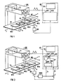
- FIG 3 eine weitere Ausführungsform, bei der ein Teil der Bearbeitungsvorrichtung parallel zur Bewegungsrichtung der zu bearbeitenden Werkstücke mitgeführt werden kann.
- 1 shows an exemplary embodiment of the laser processing device according to the invention with fixed focusing optics,
- 2 shows a further embodiment with additional fine correction of short-term fluctuations in the workpiece movement speed, and
- 3 shows a further embodiment in which a part of the machining device can be carried parallel to the direction of movement of the workpieces to be machined.
Gemäß FIG 1 enthält die erfindungsgemäße Laserbearbeitungsvorrichtung LBG einen Generator LG zur Erzeugung des Laserstrahles LS. Ferner sind Mittel zur Führung des Strahles auf der Bearbeitungsebene BE enthalten. In der FIG 1 sind diese beispielhaft in Form mindestens eines ansteuerbaren Spiegels SP dargestellt. Dieser lenkt zum einen den vom Generator LG erzeugten Laserstrahl LS durch die Fokussieroptik FO hindurch auf die Bearbeitungsebene BE um. Zum anderen wird hierdurch die Führung insbesondere des Fokuspunktes FS des Laserstrahles innerhalb des maximal zur Verfügung stehenden Bildfeldes BF auf der Bearbeitungsebene BE ermöglicht. Hierzu werden dem Strahlführungs mittel Positioniersignale Sx, Sy zugeführt, welche von einer Bearbeitungssteuerung BS aus den zur jeweils gewünschten Bearbeitung bzw. Beschriftung gehörigen Daten BSD zur Laserstrahlführung gebildet werden. Gemäß FIG 1 enthält die Bearbeitungssteuerung BS bevorzugt eine Datenaufbereitung DA zur Bildung der Strahlführungsdaten BSD aus Eingabegrößen, und eine Anpassungseinheit APE zur Ausgabe der Daten an die Strahlführungsmittel, d.h. insbesondere mindestens an den Spiegel SP.According to FIG. 1, the laser processing device LBG according to the invention contains a generator LG for generating the laser beam LS. Means for guiding the beam on the processing plane BE are also included. These are shown by way of example in FIG. 1 in the form of at least one controllable mirror SP. On the one hand, this deflects the laser beam LS generated by the generator LG through the focusing optics FO onto the processing plane BE. On the other hand, this enables the focal point FS of the laser beam to be guided within the maximum available image field BF on the processing plane BE. For this, the beam guidance by means of positioning signals S x , S y , which are formed by a processing control BS from the data BSD associated with the respectively desired processing or labeling for laser beam guidance. According to FIG. 1, the processing control BS preferably contains a data preparation DA for forming the beam guidance data BSD from input variables, and an adaptation unit APE for outputting the data to the beam guidance means, ie in particular at least to the mirror SP.
Erfindungsgemäß werden die zu bearbeitenden Werkstücke entlang der Bearbeitungsebene nahezu kontinuierlich geführt. Hierzu dient in FIG 1 beispielhaft ein Transportband TB. Hiermit werden mit nahezu konstanter Bewegungsgeschwindigkeit v beispielhaft die Werkstücke WS1...WS4 in (-x)-Richtung in der Bearbeitungsebene BE geführt. In FIG 1 befindet sich das Werkstück WS3 gerade nahezu im Zentrum des Bildfeldes BF unterhalb der Fokus- sieroptik FO. Zum Ausgleich dieser kontinuierlichen Werkstückbewegung werden die Strahlführungsdaten BSD neuerungsgemäß an die Bewegungsgeschwindigkeit v der Werkstücke in der Bearbeitungsebene angepaßt, und danach bevorzugt in Form der Positioniersignale Sx, Sy an die Strahlführungsmittel ausgegeben. Die Anpassung erfolgt bevorzugt durch die Anpassungseinheit APE innerhalb der Bearbeitungssteuerung BS. Hierzu wird der Istwert der Bewegungsgeschwindigkeit v der Werkstücke bevorzugt über einen Meßgeber MG erfaßt und der Anpassungseinheit APE zugeführt.According to the invention, the workpieces to be machined are guided almost continuously along the machining plane. A conveyor belt TB serves as an example in FIG. Hereby, the workpieces WS1 ... WS4 are guided in the (-x) direction in the machining plane BE with an almost constant speed of movement v. In FIG. 1, the workpiece WS3 is located almost in the center of the image field BF below the focusing optics FO. To compensate for this continuous workpiece movement, the beam guidance data BSD are, according to the innovation, adapted to the speed of movement v of the workpieces in the processing plane, and are then preferably output to the beam guidance means in the form of the positioning signals S x , S y . The adaptation is preferably carried out by the adaptation unit APE within the processing control BS. For this purpose, the actual value of the speed of movement v of the workpieces is preferably detected via a measuring transducer MG and fed to the adaptation unit APE.
Aufgrund der Eigenbewegung des jeweils zu bearbeitenden Werkstückes muß bei der Führung des Laserstrahles auf der Bearbeitungsebene nicht mehr das gesamte zur Verfügung stehende Bildfeld BF ausgenutzt werden. Wird gemäß einer ersten Ausführungsform der Erfindung die Bewegungsgeschwindigkeit v der Werkstücke durch entsprechende Anpassung der Strahlführungsdaten nahezu vollständig kompensiert, so muß der Strahl kaum mehr an die Ränder des Bildfeldes BF geführt werden, an denen ein Werkstück in das Bildfeld eintritt bzw. dieses wieder verläßt. Werden ge mäß FIG 1 die Werkstücke beispielhaft in (-x)-Koordinatenrichtung in der Bearbeitungsebene BE geführt, so treten die Werkstücke im Randbereich R1 in das Bildfeld BF ein und im Randbereich R2 aus diesem wieder aus. Der Fokuspunkt FS wird somit nur noch in (±y)-Koordinatenrichtung unter Umständen bis zur Bildfeldgrenze geführt, während er sich in (±x)-Richtung zunehmend im Zentrum des Bildfeldes BF aufhält und nicht mehr in die Randbereiche R1, R2 geführt wird. Dieser Umstand kann gemäß weiteren Ausführungsformen der Erfindung weiter genutzt werden.Due to the inherent movement of the workpiece to be machined, the entire available image field BF no longer has to be used when guiding the laser beam on the machining plane. If, according to a first embodiment of the invention, the movement speed v of the workpieces is almost completely compensated for by appropriate adaptation of the beam guidance data, the beam hardly needs to be guided to the edges of the image field BF at which a workpiece enters or leaves the image field. Are ge 1, the workpieces are guided, for example, in the (-x) coordinate direction in the processing plane BE, the workpieces enter the image field BF in the edge region R1 and exit the latter in the edge region R2. The focal point FS is thus only guided in the (± y) coordinate direction under certain circumstances up to the image field boundary, while it is increasingly located in the center of the image field BF in the (± x) direction and is no longer guided into the edge regions R1, R2. This fact can be used according to further embodiments of the invention.
Ist es z.B. bei bestimmten Bearbeitungen nicht notwendig, in (±y)-Richtung den gesamten Durchmesser des maximal zur Verfügung stehenden Bildfeldes BF auszunutzen, so kann aufgrund der oben beschriebenen Bildfeldeinengung in (±x)-Richtung das Bildfeld insgesamt kleiner ausgewählt werden, z.B. durch Verstellung der Fokussieroptik FO. Hierdurch wird die Fokussierfähigkeit des Laserstrahles verbessert, so daß z.B. eine größere Energiedichte im Fokuspunkt FS zur Werkstückbearbeitung zur Verfügung steht.Is it e.g. With certain machining operations it is not necessary to use the entire diameter of the maximum available image field BF in the (± y) direction, the overall image field can be selected smaller, e.g. by adjusting the focusing optics FO. This improves the focusability of the laser beam, so that e.g. a greater energy density is available at the focal point FS for workpiece machining.
Werden in einer anderen Ausführungsform die aufgrund der Bildfeldeinengung in (±x)-Richtung zunehmend nicht ausgenutzten Randbereiche R1, R2 des Bildfeldes BF durch entsprechende Vorgabe der Strahlführungsdaten BSD dennoch ausgenutzt, so hat dies in FIG 1 in (±x)-Richtung eine Erhöhung des nutzbaren Bearbeitungsfeldes in der Bearbeitungsebene BE zur Folge. Es können somit größere Werkstückbereiche in einem Arbeitsgang bearbeitet werden.If, in another embodiment, the edge regions R1, R2 of the image field BF, which are increasingly not used due to the narrowing of the image field in the (± x) direction, are nevertheless used by corresponding specification of the beam guidance data BSD, this has an increase in the (± x) direction in FIG. 1 of the usable processing field in the processing plane BE. Larger workpiece areas can thus be machined in one operation.
In einer weiteren, besonders vorteilhaften Ausführungsform wird mit dem Bearbeitungsvorgang eines der in der Bearbeitungsebene nahezu kontinuierlich entlang geführten Werkstücke näherungsweise in dem Randbereich des Bildfeldes BF begonnen, an dem das Werkstück in das Bildfeld eintritt. In FIG 1 ist dies der Randbereich R1. Erfindungsgemäß kann nun die Bewegungsgeschwindigkeit v der Werkstücke so auf die für einen Bearbeitungsvorgang notwendige mittlere Zeitdauer abgestimmt werden, daß die Bearbeitung gerade dann abgeschlossen ist, wenn das bearbeitete Werkstück bzw. der Werkstückbereich aus dem Bildfeld BF am entsprechenden Randbereich austritt. In FIG 1 ist dies beispielsweise der Randbereich R2. Hierdurch ist es möglich, die Bewegungsgeschwindigkeit v der Werkstücke und damit den Gesamtdurchsatz der Laserbearbeitungsvorrichtung weiter zu erhöhen. Während eines Bearbeitungsvorganges wird somit die überhöhte Bewegungsgeschwindigkeit v nicht mehr durch die Vortriebsbewegung des Fokussierpunktes FS in Bearbeitungsrichtung ausgeglichen. Der Fokuspunkt wandert somit während des Bearbeitungsvorganges allmählich von dem einen Bildfeldrandbereich, in dem der Bearbeitungsvorgang begonnen wurde, bis hin zum gegenüberliegenden Bildfeldrandbereich, in dem der Bearbeitungsvorgang beendet wird.In a further, particularly advantageous embodiment, the machining process of one of the workpieces which is guided almost continuously along the machining plane is started approximately in the edge region of the image field BF at which the workpiece enters the image field. In FIG 1, this is the edge region R1. According to the invention, the speed of movement v of the workpieces can now be matched to the average time required for a machining operation such that the machining is completed when the machined workpiece or the workpiece area emerges from the image field BF at the corresponding edge area. In FIG. 1, this is, for example, the edge area R2. This makes it possible to further increase the speed of movement v of the workpieces and thus the overall throughput of the laser processing device. During a machining process, the excessive movement speed v is therefore no longer compensated for by the advancing movement of the focal point FS in the machining direction. The focus point thus gradually moves during the processing operation from the one image field edge area in which the processing operation was started to the opposite image field edge area in which the processing operation is ended.
So treten in FIG 1 die Werkstücke WS1...WS4 im Randbereich R1 in das Bildfeld BF ein. Der Fokuspunkt FS wird nun so positioniert, daß mit Eintritt eines Werkstückes in das Bildfeld dessen Bearbeitung in diesem Randbereich begonnen wird. Da die Geschwindigkeit v der Werkstücke in (-x)-Richtung größer ist als die maximal mögliche Bearbeitungsgeschwindigkeit in (+x)-Richtung, wird der Fokuspunkt während der Bearbeitung allmählich bis zum gegenüberliegenden Randbereich R2 "mitgenommen". Gemäß der Neuerung sind die Bewegungsgeschwindigkeit v und die mittlere Dauer eines Bearbeitungsvorganges so aufeinander abgestimmt, daß der Bearbeitungsvorgang mit Erreichen dieses Randbereiches R2 abgeschlossen ist. Die Totzeit bis zum Beginn des nächsten Bearbeitungsvorganges, welche besonders vorteilhaft z.B. durch den Abstand der Werkstücke WS1...WS4 auf dem Transportband TB eingestellt werden kann, wird genutzt zur Neupositionierung des Laserstrahles auf den wiederum im Randbereich R1 liegenden Startpunkt für den folgenden Bearbeitungsvorgang.In FIG. 1, the workpieces WS1 ... WS4 enter the image field BF in the edge region R1. The focal point FS is now positioned in such a way that when a workpiece enters the image field, its processing is started in this edge area. Since the speed v of the workpieces in the (-x) direction is greater than the maximum possible machining speed in the (+ x) direction, the focal point is gradually "taken along" to the opposite edge region R2 during the machining. According to the innovation, the movement speed v and the average duration of a machining process are coordinated with one another in such a way that the machining process is completed when this edge region R2 is reached. The dead time until the start of the next machining process, which is particularly advantageous e.g. can be adjusted by the distance of the workpieces WS1 ... WS4 on the conveyor belt TB, is used to reposition the laser beam on the starting point, which in turn is located in the peripheral area R1, for the subsequent machining process.
Gemäß einer weiteren Ausführungsform der Erfindung sind Bewegungsmittel vorhanden, welche eine Bewegung zumindest eines Teiles der Laserbearbeitungsvorrichtung während eines Bearbeitungsvorganges in Richtung der Bewegung der Werkstücke ermöglichen.According to a further embodiment of the invention, movement means are present which enable movement of at least a part of the laser machining device during a machining process in the direction of the movement of the workpieces.
In FIG 3 ist eine derartige Ausführungsform beispielhaft dargestellt. Dabei enthält die Laserbearbeitungsvorrichtung LBG einen feststehenden Teil FT, welcher beispielsweise den Generator LG zur Erzeugung des Laserstrahles LS beinhaltet. Desweiteren ist ein beweglicher Teil BT vorhanden, welcher die Mittel zur Strahlführung enthält, insbesondere den mindestens einen Spiegel SP. Der bewegliche Teil BT ist bevorzugt mittels Hängeschienen HS parallel zur (±x)-Bewegungsrichtung der Werkstücke verschiebbar. Zur Übertragung des Laserstrahles zwischen dem feststehenden und den beweglichen Teil dient bevorzugt ein optischer Lichtleiter LL. Erfindungsgemäß gibt die Bearbeitungsvorrichtung die Strahlführungsdaten angepaßt an die Relativgeschwindigkeit zwischen den Werkstücken in der Bearbeitungsebene und den Strahlführungsmittel im beweglichen Teil BT vor.Such an embodiment is shown as an example in FIG. The laser processing device LBG contains a fixed part FT, which contains, for example, the generator LG for generating the laser beam LS. Furthermore, there is a movable part BT which contains the means for beam guidance, in particular the at least one mirror SP. The movable part BT can preferably be moved parallel to the (± x) movement direction of the workpieces by means of hanging rails HS. An optical light guide LL is preferably used to transmit the laser beam between the fixed and the movable part. According to the invention, the processing device specifies the beam guidance data adapted to the relative speed between the workpieces in the processing plane and the beam guidance means in the movable part BT.
Mit dieser Vorrichtung ist es möglich, die Bewegungsgeschwindigkeit v der Werkstücke in der Bearbeitungsebene weiter zu erhöhen, und/oder in Richtung der Bewegung der Werkstücke das nutzbare Bearbeitungsfeld zu vergrößern. Hierzu wird erfindungsgemäß der bewegliche Teil BT der Laserbearbeitungsvorrichtung für die Dauer eines Bearbeitungsvorganges mit geringerer Geschwindigkeit in Richtung der Werkstückbewegung nachgeführt. Auch hier werden die Totzeiten zwischen einzelnen Bearbeitungsvorgängen benutzt, um den beweglichen Teil BT der Bearbeitungsvorrichtung in die Ausgangsposition zurückzuführen. Besonders vorteilhaft wird während eines Bearbeitungsvorganges sowohl der bewegliche Teil der Bearbeitungsvorrichtung als auch der Fokuspunkt FS in der bereits anhand von FIG 1 näher beschriebenen Weise von einem Randbereich bis zum gegenüberliegenden Randbereich des Bildfeldes BF mitgenommen.With this device it is possible to further increase the speed of movement v of the workpieces in the machining plane and / or to enlarge the usable machining field in the direction of the movement of the workpieces. For this purpose, according to the invention, the movable part BT of the laser machining device is tracked at a lower speed in the direction of the workpiece movement for the duration of a machining operation. The dead times between individual machining processes are also used here in order to return the movable part BT of the machining device to the starting position. During a processing operation, both the movable part of the processing device and the focal point FS are particularly advantageously carried along from one edge region to the opposite edge region of the image field BF in the manner already described with reference to FIG. 1.
In FIG 2 ist eine weitere vorteilhafte Ausführungsform der Erfindung dargestellt. Mit deren Hilfe ist es möglich, kurzzeitige Schwankungen im Istwert der Bewegungsgeschwindigkeit v der Werkstücke so auszugleichen, daß nahezu keine Abweichungen des Fokuspunktes FS des Laserstrahles LS von dem durch die Strahlführungs daten BSD vorgegebenen, idealen Verlauf auftreten. Hierzu wird über einen Geber MWB der Mittelwert vM der Bewegungsgeschwindigkeit v der Werkstücke in der Bearbeitungsebene BE bestimmt. Mittels einer Grundkorrektureinheit GKE werden die bevorzugt von einer Datenaufbereitung DA aus Vorgabewerten gebildeten Strahlführungsdaten BSD an den Mittelwert vM angepaßt. Die derart korrigierten Strahlführungsdaten BSD′ werden desweiteren einem Modulator MD zugeführt, welcher diese wiederum an die Abweichung Δv des Istwertes v des Bewegungsgeschwindigkeit der Werkstücke vom dazugehörigen Mittelwert vM anpaßt. Die derart korrigierten Strahlführungsdaten BSD˝ werden schließlich bevorzugt in Form von Positioniersignalen Sx, Sy an die Strahlführungsmittel in der Laserbearbeitungsvorrichtung ausgegeben. Mit dieser Ausführungsform ist eine schnelle Feinanpassung der Strahlführungsdaten an kurzzeitige Schwankungen des Istwertes der Bewegungsgeschwindigkeit der Werkstücke möglich.2 shows a further advantageous embodiment of the invention. With their help, it is possible to compensate for short-term fluctuations in the actual value of the speed of movement v of the workpieces such that there are almost no deviations of the focal point FS of the laser beam LS from that caused by the beam guidance data, BSD given, ideal course occur. For this purpose, the mean value v M of the speed of movement v of the workpieces in the machining plane BE is determined via a transmitter MWB. By means of a basic correction unit GKE, the beam guidance data BSD, which are preferably formed by a data preparation DA from default values, are adapted to the mean value v M. The beam guidance data BSD 'corrected in this way are further fed to a modulator MD, which in turn adapts them to the deviation Δv of the actual value v of the speed of movement of the workpieces from the associated mean value V M. The beam guidance data BSD˝ corrected in this way are finally preferably output in the form of positioning signals S x , S y to the beam guidance means in the laser processing device. With this embodiment, a rapid fine adjustment of the beam guidance data to short-term fluctuations in the actual value of the speed of movement of the workpieces is possible.
Claims (4)
Applications Claiming Priority (2)
| Application Number | Priority Date | Filing Date | Title |
|---|---|---|---|
| DE8906578U DE8906578U1 (en) | 1989-05-29 | 1989-05-29 | |
| DE8906578U | 1989-05-29 |
Publications (4)
| Publication Number | Publication Date |
|---|---|
| EP0400476A2 true EP0400476A2 (en) | 1990-12-05 |
| EP0400476A3 EP0400476A3 (en) | 1991-02-06 |
| EP0400476B1 EP0400476B1 (en) | 1993-03-31 |
| EP0400476B2 EP0400476B2 (en) | 1998-08-12 |
Family
ID=6839628
Family Applications (1)
| Application Number | Title | Priority Date | Filing Date |
|---|---|---|---|
| EP90109821A Expired - Lifetime EP0400476B2 (en) | 1989-05-29 | 1990-05-23 | Laser machining method |
Country Status (2)
| Country | Link |
|---|---|
| EP (1) | EP0400476B2 (en) |
| DE (2) | DE8906578U1 (en) |
Cited By (13)
| Publication number | Priority date | Publication date | Assignee | Title |
|---|---|---|---|---|
| EP0495647A1 (en) * | 1991-01-17 | 1992-07-22 | United Distillers Plc | Dynamic laser marking |
| GB2252068B (en) * | 1991-01-17 | 1994-05-04 | United Distillers Plc | Dynamic laser marking |
| US5698119A (en) * | 1994-12-16 | 1997-12-16 | Alza Corporation | Apparatus for forming dispenser delivery ports |
| US6130402A (en) * | 1996-04-26 | 2000-10-10 | Servicio Industrial De Marcaje Y Codification, S.A. | System and process for marking or perforating |
| EP1452263A1 (en) * | 2003-02-27 | 2004-09-01 | Osmotica Corp. | Laser drilling system and method |
| US6791592B2 (en) | 2000-04-18 | 2004-09-14 | Laserink | Printing a code on a product |
| DE102006036544A1 (en) * | 2006-08-04 | 2008-02-07 | Patent-Treuhand-Gesellschaft für elektrische Glühlampen mbH | Optoelectronic module |
| CN102470483A (en) * | 2009-08-03 | 2012-05-23 | 东丽工程株式会社 | Marking device and method |
| RU2478588C2 (en) * | 2006-10-18 | 2013-04-10 | Тиама | Method and unit for marking transparent or semitransparent articles at high temperature |
| WO2016083909A1 (en) * | 2014-11-27 | 2016-06-02 | Progetto Futuro S.R.L. | Station for processing the surfaces of ceramic products, punches, dies and processing method |
| EP2374569B1 (en) | 2010-03-15 | 2018-11-07 | Ewag AG | Laser processing device and method for manufacturing a rotation symmetric tool |
| EP2314412B1 (en) | 2009-10-22 | 2018-12-19 | Ewag AG | Laser machining apparatus and method for forming a surface on an unfinished product |
| US10583668B2 (en) | 2018-08-07 | 2020-03-10 | Markem-Imaje Corporation | Symbol grouping and striping for wide field matrix laser marking |
Citations (4)
| Publication number | Priority date | Publication date | Assignee | Title |
|---|---|---|---|---|
| US4049945A (en) * | 1973-10-10 | 1977-09-20 | Winkler & Dunnebier Maschinenfabrik Und Eisengiesserei Kg | Method of and apparatus for cutting material to shape from a moving web by burning |
| US4297559A (en) * | 1979-05-10 | 1981-10-27 | Olin Corporation | Apparatus for controlled perforation of moving webs with fixed focus laser beam |
| DD243798A1 (en) * | 1985-10-17 | 1987-03-11 | Erfurt Mikroelektronik | METHOD FOR MARKING SMALL OBJECTS, ESPECIALLY ELECTRONIC COMPONENTS |
| EP0215389A2 (en) * | 1985-09-06 | 1987-03-25 | Walter Sticht | Printing and marking process for construction elements |
-
1989
- 1989-05-29 DE DE8906578U patent/DE8906578U1/de not_active Expired - Lifetime
-
1990
- 1990-05-23 DE DE9090109821T patent/DE59001100D1/en not_active Expired - Fee Related
- 1990-05-23 EP EP90109821A patent/EP0400476B2/en not_active Expired - Lifetime
Patent Citations (4)
| Publication number | Priority date | Publication date | Assignee | Title |
|---|---|---|---|---|
| US4049945A (en) * | 1973-10-10 | 1977-09-20 | Winkler & Dunnebier Maschinenfabrik Und Eisengiesserei Kg | Method of and apparatus for cutting material to shape from a moving web by burning |
| US4297559A (en) * | 1979-05-10 | 1981-10-27 | Olin Corporation | Apparatus for controlled perforation of moving webs with fixed focus laser beam |
| EP0215389A2 (en) * | 1985-09-06 | 1987-03-25 | Walter Sticht | Printing and marking process for construction elements |
| DD243798A1 (en) * | 1985-10-17 | 1987-03-11 | Erfurt Mikroelektronik | METHOD FOR MARKING SMALL OBJECTS, ESPECIALLY ELECTRONIC COMPONENTS |
Cited By (22)
| Publication number | Priority date | Publication date | Assignee | Title |
|---|---|---|---|---|
| WO1992012820A1 (en) * | 1991-01-17 | 1992-08-06 | United Distillers Plc | Dynamic laser marking |
| GB2252068B (en) * | 1991-01-17 | 1994-05-04 | United Distillers Plc | Dynamic laser marking |
| AU659131B2 (en) * | 1991-01-17 | 1995-05-11 | United Distillers Plc | Dynamic laser marking |
| US5653900A (en) * | 1991-01-17 | 1997-08-05 | United Distillers Plc | Dynamic laser marking |
| EP0495647A1 (en) * | 1991-01-17 | 1992-07-22 | United Distillers Plc | Dynamic laser marking |
| US5698119A (en) * | 1994-12-16 | 1997-12-16 | Alza Corporation | Apparatus for forming dispenser delivery ports |
| US6130402A (en) * | 1996-04-26 | 2000-10-10 | Servicio Industrial De Marcaje Y Codification, S.A. | System and process for marking or perforating |
| US6829000B2 (en) | 2000-04-18 | 2004-12-07 | Laserink | Printing a code on a product |
| US6791592B2 (en) | 2000-04-18 | 2004-09-14 | Laserink | Printing a code on a product |
| EP1764180A1 (en) * | 2003-02-27 | 2007-03-21 | Osmotica Corp. | Laser drilling system and method |
| EP1452263A1 (en) * | 2003-02-27 | 2004-09-01 | Osmotica Corp. | Laser drilling system and method |
| DE102006036544A1 (en) * | 2006-08-04 | 2008-02-07 | Patent-Treuhand-Gesellschaft für elektrische Glühlampen mbH | Optoelectronic module |
| US7789573B2 (en) | 2006-08-04 | 2010-09-07 | Osram Gesellschaft Mit Beschrankter Haftung | Optoelectronic module |
| RU2478588C2 (en) * | 2006-10-18 | 2013-04-10 | Тиама | Method and unit for marking transparent or semitransparent articles at high temperature |
| RU2634130C2 (en) * | 2006-10-18 | 2017-10-24 | Тиама | Method and unit for marking transparent or semi-transparent objects at high temperature |
| CN102470483A (en) * | 2009-08-03 | 2012-05-23 | 东丽工程株式会社 | Marking device and method |
| TWI454687B (en) * | 2009-08-03 | 2014-10-01 | Toray Eng Co Ltd | Marking device and method |
| CN102470483B (en) * | 2009-08-03 | 2015-04-01 | 东丽工程株式会社 | Marking device and method |
| EP2314412B1 (en) | 2009-10-22 | 2018-12-19 | Ewag AG | Laser machining apparatus and method for forming a surface on an unfinished product |
| EP2374569B1 (en) | 2010-03-15 | 2018-11-07 | Ewag AG | Laser processing device and method for manufacturing a rotation symmetric tool |
| WO2016083909A1 (en) * | 2014-11-27 | 2016-06-02 | Progetto Futuro S.R.L. | Station for processing the surfaces of ceramic products, punches, dies and processing method |
| US10583668B2 (en) | 2018-08-07 | 2020-03-10 | Markem-Imaje Corporation | Symbol grouping and striping for wide field matrix laser marking |
Also Published As
| Publication number | Publication date |
|---|---|
| EP0400476B2 (en) | 1998-08-12 |
| DE59001100D1 (en) | 1993-05-06 |
| EP0400476A3 (en) | 1991-02-06 |
| EP0400476B1 (en) | 1993-03-31 |
| DE8906578U1 (en) | 1990-09-27 |
Similar Documents
| Publication | Publication Date | Title |
|---|---|---|
| EP0400476B1 (en) | Laser machining device | |
| DE10000469C2 (en) | Process for the continuous cutting of blanks from a continuously moving endless material and associated device | |
| DE102015202347A1 (en) | Irradiation device, processing machine and method for producing a layer of a three-dimensional component | |
| DE2725959C3 (en) | Electron beam processing equipment | |
| EP0329787A1 (en) | Method and device for laser processing of an object | |
| EP0166351A2 (en) | Device at a machine for deformation work of sheet metals | |
| DE19700853A1 (en) | Numerical control device and method for controlling the acceleration / deceleration of a spindle motor of the numerical control device | |
| EP0653791A1 (en) | Device for inscribing workpieces | |
| EP3345713A1 (en) | Method and device for process-oriented beam shape adjustment and beam orientation | |
| DE3546130A1 (en) | METHOD FOR CONTROLLING PROCESSING IN AN ELECTRIC EDMING MACHINE WITH A WIRE ELECTRODE | |
| DE2910399A1 (en) | CIRCUIT ARRANGEMENT FOR AN AUTOMATED PRESS ARRANGEMENT | |
| DE3941057C2 (en) | Method and device for contour machining of a workpiece | |
| DE4335830C2 (en) | Method and device for spark-erosive cutting of an inside corner into a workpiece by means of a wire electrode | |
| DE3504968A1 (en) | RECORDING DEVICE FOR AN OPTICAL DISK | |
| DE4412093A1 (en) | Guidance system for laser welding machine | |
| DE2931845A1 (en) | COPY MILLING MACHINE | |
| EP3606696B1 (en) | Method and device for regulating a focus of a laser beam and a laser processing head with such a device | |
| DE102018009999A1 (en) | NUMERICAL CONTROL | |
| DE19750156A1 (en) | Numerical control of a machine tool with variable radiation power | |
| EP0417623A1 (en) | Edge control system | |
| DE60117113T2 (en) | Method for acceleration and deceleration | |
| DE102018125436A1 (en) | Process for material-removing laser processing of a workpiece | |
| DE2703115C2 (en) | Photocomposing machine and method for operating the same | |
| DE4036297B4 (en) | Advance device for the tool holder of a numerically controlled lathe | |
| DE19539038A1 (en) | Arc welder with an AC powered rectifier |
Legal Events
| Date | Code | Title | Description |
|---|---|---|---|
| PUAI | Public reference made under article 153(3) epc to a published international application that has entered the european phase |
Free format text: ORIGINAL CODE: 0009012 |
|
| AK | Designated contracting states |
Kind code of ref document: A2 Designated state(s): CH DE FR IT LI |
|
| PUAL | Search report despatched |
Free format text: ORIGINAL CODE: 0009013 |
|
| 17P | Request for examination filed |
Effective date: 19901205 |
|
| AK | Designated contracting states |
Kind code of ref document: A3 Designated state(s): CH DE FR IT LI |
|
| 17Q | First examination report despatched |
Effective date: 19920226 |
|
| GRAA | (expected) grant |
Free format text: ORIGINAL CODE: 0009210 |
|
| AK | Designated contracting states |
Kind code of ref document: B1 Designated state(s): CH DE FR IT LI |
|
| REF | Corresponds to: |
Ref document number: 59001100 Country of ref document: DE Date of ref document: 19930506 |
|
| ET | Fr: translation filed | ||
| ITF | It: translation for a ep patent filed |
Owner name: STUDIO JAUMANN |
|
| PLBI | Opposition filed |
Free format text: ORIGINAL CODE: 0009260 |
|
| 26 | Opposition filed |
Opponent name: UNITED DISTILLERS PLC. Effective date: 19931223 |
|
| RAP2 | Party data changed (patent owner data changed or rights of a patent transferred) |
Owner name: ROFIN SINAR LASER GMBH |
|
| APAE | Appeal reference modified |
Free format text: ORIGINAL CODE: EPIDOS REFNO |
|
| APAC | Appeal dossier modified |
Free format text: ORIGINAL CODE: EPIDOS NOAPO |
|
| PLAW | Interlocutory decision in opposition |
Free format text: ORIGINAL CODE: EPIDOS IDOP |
|
| RTI2 | Title (correction) |
Free format text: LASER MACHINING METHOD |
|
| PUAH | Patent maintained in amended form |
Free format text: ORIGINAL CODE: 0009272 |
|
| STAA | Information on the status of an ep patent application or granted ep patent |
Free format text: STATUS: PATENT MAINTAINED AS AMENDED |
|
| REG | Reference to a national code |
Ref country code: CH Ref legal event code: PUE Owner name: SIEMENS AKTIENGESELLSCHAFT TRANSFER- ROFIN-SINAR L Ref country code: CH Ref legal event code: NV Representative=s name: E. BLUM & CO. PATENTANWAELTE |
|
| 27A | Patent maintained in amended form |
Effective date: 19980812 |
|
| AK | Designated contracting states |
Kind code of ref document: B2 Designated state(s): CH DE FR IT LI |
|
| REG | Reference to a national code |
Ref country code: CH Ref legal event code: AEN Free format text: AUFRECHTERHALTUNG DES PATENTES IN GEAENDERTER FORM |
|
| ET3 | Fr: translation filed ** decision concerning opposition | ||
| APAH | Appeal reference modified |
Free format text: ORIGINAL CODE: EPIDOSCREFNO |
|
| PGFP | Annual fee paid to national office [announced via postgrant information from national office to epo] |
Ref country code: FR Payment date: 20060519 Year of fee payment: 17 |
|
| PGFP | Annual fee paid to national office [announced via postgrant information from national office to epo] |
Ref country code: CH Payment date: 20060524 Year of fee payment: 17 |
|
| PGFP | Annual fee paid to national office [announced via postgrant information from national office to epo] |
Ref country code: IT Payment date: 20060531 Year of fee payment: 17 |
|
| PGFP | Annual fee paid to national office [announced via postgrant information from national office to epo] |
Ref country code: DE Payment date: 20060725 Year of fee payment: 17 |
|
| REG | Reference to a national code |
Ref country code: CH Ref legal event code: PFA Owner name: ROFIN-SINAR LASER GMBH Free format text: ROFIN-SINAR LASER GMBH#BERZELIUSSTRASSE 87#22113 HAMBURG (DE) -TRANSFER TO- ROFIN-SINAR LASER GMBH#BERZELIUSSTRASSE 87#22113 HAMBURG (DE) |
|
| REG | Reference to a national code |
Ref country code: CH Ref legal event code: PL |
|
| PG25 | Lapsed in a contracting state [announced via postgrant information from national office to epo] |
Ref country code: LI Free format text: LAPSE BECAUSE OF NON-PAYMENT OF DUE FEES Effective date: 20070531 Ref country code: CH Free format text: LAPSE BECAUSE OF NON-PAYMENT OF DUE FEES Effective date: 20070531 |
|
| REG | Reference to a national code |
Ref country code: FR Ref legal event code: ST Effective date: 20080131 |
|
| PG25 | Lapsed in a contracting state [announced via postgrant information from national office to epo] |
Ref country code: DE Free format text: LAPSE BECAUSE OF NON-PAYMENT OF DUE FEES Effective date: 20071201 |
|
| PG25 | Lapsed in a contracting state [announced via postgrant information from national office to epo] |
Ref country code: FR Free format text: LAPSE BECAUSE OF NON-PAYMENT OF DUE FEES Effective date: 20070531 |
|
| PG25 | Lapsed in a contracting state [announced via postgrant information from national office to epo] |
Ref country code: IT Free format text: LAPSE BECAUSE OF NON-PAYMENT OF DUE FEES Effective date: 20070523 |