EP0399651A2 - Apparatus and method of scanning image data - Google Patents
Apparatus and method of scanning image data Download PDFInfo
- Publication number
- EP0399651A2 EP0399651A2 EP90304137A EP90304137A EP0399651A2 EP 0399651 A2 EP0399651 A2 EP 0399651A2 EP 90304137 A EP90304137 A EP 90304137A EP 90304137 A EP90304137 A EP 90304137A EP 0399651 A2 EP0399651 A2 EP 0399651A2
- Authority
- EP
- European Patent Office
- Prior art keywords
- image
- light
- line
- rate
- media
- Prior art date
- Legal status (The legal status is an assumption and is not a legal conclusion. Google has not performed a legal analysis and makes no representation as to the accuracy of the status listed.)
- Granted
Links
Images
Classifications
-
- H—ELECTRICITY
- H04—ELECTRIC COMMUNICATION TECHNIQUE
- H04N—PICTORIAL COMMUNICATION, e.g. TELEVISION
- H04N1/00—Scanning, transmission or reproduction of documents or the like, e.g. facsimile transmission; Details thereof
- H04N1/04—Scanning arrangements, i.e. arrangements for the displacement of active reading or reproducing elements relative to the original or reproducing medium, or vice versa
- H04N1/0402—Scanning different formats; Scanning with different densities of dots per unit length, e.g. different numbers of dots per inch (dpi); Conversion of scanning standards
- H04N1/0408—Different densities of dots per unit length
- H04N1/0411—Different densities of dots per unit length in the main scanning direction
-
- G—PHYSICS
- G06—COMPUTING; CALCULATING OR COUNTING
- G06T—IMAGE DATA PROCESSING OR GENERATION, IN GENERAL
- G06T3/00—Geometric image transformation in the plane of the image
- G06T3/40—Scaling the whole image or part thereof
-
- H—ELECTRICITY
- H04—ELECTRIC COMMUNICATION TECHNIQUE
- H04N—PICTORIAL COMMUNICATION, e.g. TELEVISION
- H04N1/00—Scanning, transmission or reproduction of documents or the like, e.g. facsimile transmission; Details thereof
- H04N1/04—Scanning arrangements, i.e. arrangements for the displacement of active reading or reproducing elements relative to the original or reproducing medium, or vice versa
- H04N1/0402—Scanning different formats; Scanning with different densities of dots per unit length, e.g. different numbers of dots per inch (dpi); Conversion of scanning standards
- H04N1/042—Details of the method used
- H04N1/0443—Varying the scanning velocity or position
-
- H—ELECTRICITY
- H04—ELECTRIC COMMUNICATION TECHNIQUE
- H04N—PICTORIAL COMMUNICATION, e.g. TELEVISION
- H04N1/00—Scanning, transmission or reproduction of documents or the like, e.g. facsimile transmission; Details thereof
- H04N1/04—Scanning arrangements, i.e. arrangements for the displacement of active reading or reproducing elements relative to the original or reproducing medium, or vice versa
- H04N1/047—Detection, control or error compensation of scanning velocity or position
- H04N1/0473—Detection, control or error compensation of scanning velocity or position in subscanning direction, e.g. picture start or line-to-line synchronisation
-
- H—ELECTRICITY
- H04—ELECTRIC COMMUNICATION TECHNIQUE
- H04N—PICTORIAL COMMUNICATION, e.g. TELEVISION
- H04N1/00—Scanning, transmission or reproduction of documents or the like, e.g. facsimile transmission; Details thereof
- H04N1/04—Scanning arrangements, i.e. arrangements for the displacement of active reading or reproducing elements relative to the original or reproducing medium, or vice versa
- H04N1/10—Scanning arrangements, i.e. arrangements for the displacement of active reading or reproducing elements relative to the original or reproducing medium, or vice versa using flat picture-bearing surfaces
- H04N1/1013—Scanning arrangements, i.e. arrangements for the displacement of active reading or reproducing elements relative to the original or reproducing medium, or vice versa using flat picture-bearing surfaces with sub-scanning by translatory movement of at least a part of the main-scanning components
-
- H—ELECTRICITY
- H04—ELECTRIC COMMUNICATION TECHNIQUE
- H04N—PICTORIAL COMMUNICATION, e.g. TELEVISION
- H04N1/00—Scanning, transmission or reproduction of documents or the like, e.g. facsimile transmission; Details thereof
- H04N1/04—Scanning arrangements, i.e. arrangements for the displacement of active reading or reproducing elements relative to the original or reproducing medium, or vice versa
- H04N1/19—Scanning arrangements, i.e. arrangements for the displacement of active reading or reproducing elements relative to the original or reproducing medium, or vice versa using multi-element arrays
- H04N1/191—Scanning arrangements, i.e. arrangements for the displacement of active reading or reproducing elements relative to the original or reproducing medium, or vice versa using multi-element arrays the array comprising a one-dimensional array, or a combination of one-dimensional arrays, or a substantially one-dimensional array, e.g. an array of staggered elements
- H04N1/192—Simultaneously or substantially simultaneously scanning picture elements on one main scanning line
- H04N1/193—Simultaneously or substantially simultaneously scanning picture elements on one main scanning line using electrically scanned linear arrays, e.g. linear CCD arrays
-
- H—ELECTRICITY
- H04—ELECTRIC COMMUNICATION TECHNIQUE
- H04N—PICTORIAL COMMUNICATION, e.g. TELEVISION
- H04N2201/00—Indexing scheme relating to scanning, transmission or reproduction of documents or the like, and to details thereof
- H04N2201/04—Scanning arrangements
- H04N2201/047—Detection, control or error compensation of scanning velocity or position
- H04N2201/04753—Control or error compensation of scanning position or velocity
- H04N2201/04755—Control or error compensation of scanning position or velocity by controlling the position or movement of a scanning element or carriage, e.g. of a polygonal mirror, of a drive motor
Definitions
- the present invention relates to methods and apparatus for scanning images contained on planar media and producing output signals correlated to light reflected from such images. More particularly, the present invention relates to image scanners which employ an array of light sensitive elements mounted in a scanning head for movement across a plane generally parallel to the image plane for producing a series of output signals correlated to the image on the media.
- Contemporary image scanners typically are configured to produce relative motion between an array of light sensitive elements mounted in a scanning head and the image that is intended to have its contents converted to output signals manageable by data processing. That is, some such scanners sometimes move the image relative to the array while others move the array relative to the image and still others move both the image and the array. Generally, such scanners employ drive motors removing a carriage that contains the scanning head with the motor intended to cause the scanning to occur at a relatively constant speed. Some systems will employ scanner sampling that is physically controlled by the position of the scanning head so that the sample is relatively independent of the scanner movement thereby producing a relatively constant image scanning rate or pixel density against the image under consideration.
- None of the known prior art devices allow the correlation of the speed of scanning in direct relation to a predetermined pixel density so that constant scanner head sampling is possible.
- the present invention is an apparatus and process for allowing the system user to preselect the desired resolution of pixel density in a scanner device.
- Image sensing elements mechanically traverse a document to sense the average level of the reflective light.
- the light exposure time is kept constant for a high number of pixels per inch by moving the sensor at a relatively slow rate. For lower numbers of pixels per inch, the sensor is moved at a higher speed rate. By having control over the sensor speed, the desired resolution and pixels per inch is achieved.
- the apparatus and environment of the present invention for scaling image data sensed from a planar media includes a device wherein the image on the media is scanned by a scanner head which has an array of elements each capable of detecting the level of light reflected from the media image at a particular spot under consideration.
- the elements are retained in the head in a generally elongated linear configuration and the head is mounted for movement through a plane parallel to the media image plane so that light from a source illuminating the media image is reflected into the array of elements.
- the invention includes an arrangement for generating a signal which reflects a predetermined pixel sampling density that the user selects.
- the scanner head is moved through the plane parallel to the media image plane, and this moving apparatus is responsive to the pixel sampling density related signal that is generated for moving the scanner head at a rate that is directly correlated to this predetermined and preselected pixel sampling density.
- a constant rate sampling means for sampling the elements of the scanner head as it moves through the plane parallel to the media image.
- the present invention for scanning an image that is present on a planar media uses the scanning heads which are generally in a linear array of discreet light sensor elements positioned to detect light reflected from the media.
- the elements of the array are sampled at a substantially constant rate while the present invention contemplates the positioning of the light sensor array in an initial location over the media image in proximity to an edge of the media.
- the user determines the image scaling density as a function of the number of pixels per geometric unit of image that is required for recording.
- the light sensor array is thus moved across the image from the initial location image edge at a rate correlated to this predetermined image scaling density.
- scaling is accomplished to allow arbitrarily excellent accuracy of data scanned. It is possible to scan at faster rates for lower resolutions at the users option. Further, no significant or important portion of the image is discarded and no expensive electronic hardware averaging is required. Still further, it is not necessary to employ relatively slow software averaging to produce the desired result.
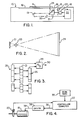
- FIGs. 1-3 A typical machine environment for implementing the present invention is shown in Figs. 1-3 in the form of scanner 10.
- document 11 is positioned with one side facing downwards on transparent platen 12 for scanning so as to convert the visual images contained thereon into an electronic image form that is useable by data processing machines.
- the scanning is accomplished by movable carriage 15 which contains a linear light source 16 and a reflecting mirror 17.
- Motor 15 is mechanically coupled to carriage 15 as by gears, cables or the like, to move carriage 15 along the length of platen 12.
- the reflected light is redirected by movable corner mirror 19 into lens 20 and thence into sensor 21.
- mirror 19 is mounted for movement concurrently with carriage 15 but at one half the velocity of carriage 15 so that the optical path from scan line 21 to sensor 21 is maintained constant in length.
- Sensor 21 is preferably a charge coupled device (CCD) configured as a linear serial array of discrete detector elements or cells.
- CCD charge coupled device
- CCD's which can distinguish 300 of these cells per inch on the document provide good quality resolution, and are readily available from contemporary commercial sources.
- the typical 8.5 inch image scan line 24 (note Fig. 1) is reduced as it passes through lens 20 in a ratio of 7.5:1 before reaching the CCD 21 detector array.
- the electrical signal content of sensor 21 is periodically read out as carriage 15 moves along the length of document 11 on platen 12.
- sensor 21 is configured with 2250 sensors per inch, it is possible with appropriate controls to record image densities of 300x300 detected pixel elements per square inch from the document.
- CCD 21 The output of CCD 21 is coupled to electronic controller 22 where it is converted as described below in conjunction with Fig. 3. Controller 22 introduces drive signals to motor 18 and may also receive position or movement feedback information relative to carriage 15 such as from the output of a tachometer detector arrangement 23.
- Fig. 3 illustrates one arrangement for reading out the contents of sensor 21.
- the contents of every other detector cell of sensor 21 is coupled in parallel into analog shift register 25 while the signals present in the other, intervening cells are coupled in parallel into analog shift register 26. That is, in the example shown, the contents of the odd numbered cells of sensor 21 are periodically transferred to shift register 25 whereas the even numbered cells have their contents transferred to shift register 26 at the same time.
- the signals loaded into registers 25 and 26 are analog signals representative of various reflected light levels. Their electrical magnitude corresponds to the average of the light reflected from a small increment of the surface of document 11 over a predetermined period of time. Subsequent to transfer into registers 25 and 26, these signals are shifted serially into an analog to digital converter (A/D) 29. A variety of appropriate analog to digital converters are commercially available for this purpose.
- the output 30 of A/D 29 is a sequence of bytes of data. Each of those bytes is encoded so as to correspond digitally to the magnitude of a discrete one of the analog signals retrieved from shift registers 25 and 26, and thus each byte corresponds to the magnitude of reflected light present at one of the cells of array 21. That is, if array 21 images 300 cells per inch, output 30 of A/D 29 comprises a similar 300 bytes per inch.
- Scan line 24 typically represents the width or length of the document for which scanning is occurring. Assuming scan line 24 is the narrower or 8.5 inch dimension and this is referenced as the x-dimension, the scan control of the present invention relates to maintaining the particular velocity in the y-direction so as to determine the y-direction scaling and pixel density in general.
- FIG. 1 The elements of FIG. 1 relating to the present invention are shown somewhat schematically in FIG. 4.
- the user determines the intended y-direction scan rate and enters this via input device 35.
- This scan rate is represented by a digital quantity and originates from a keyboard, host computer, communication link or the like.
- the digital scan rate code is stored in the controller computer 22 and used to provide an enabling signal 36 to motor driver circuit 38 and thence to the drive motor 18. If drive motor 18 is a stepper motor for example, the timing between drive pulses produced over line 36 over driver 38 and into line 39 has those pulses timed appropriately for causing the carriage 15 to move with a velocity correlated to the scan rate data entered through input device 35. This is described in somewhat greater detail below in conjunction with FIGS. 5 and 6.
- Tachometer 23 generates feedback signals to controller computer 22 so that appropriate corrective action is available to computer 22 to insure that the drive signals appearing over line 36 compensate for any shift in velocity necessary to maintain the desired scanning velocity.
- the speed of the scanner is adjusted while maintaining the sampling rate constant to produce uniform y-direction scaling. That is, the sampling rate by which the samples of light level contained in CCD 21 is maintained constant and gated into analog shift registers 25 and 26 at a predetermined constant rate. Therefore, the actual pixel density and, as a result, the resolution of the scanned image is controlled directly by this y-direction velocity control.
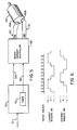
- FIG. 5 illustrates an embodiment wherein the present invention is implemented using a stepper motor.
- the FIG. 5 embodiment does not require the use of a tachometer.
- the image sensor carriage 15 is moved underneath the paper or other object on the glass platen 12 such as by a cable and pulley arrangement with stepper motor 18.
- stepper motors are driven by sequentially energizing two drive windings with electrical currents that are 90 o out of phase with one another.
- the direction of rotation is a function of the leading and lagging relationships of the winding phase currents.
- Each of the two windings 49A and 49B are digitally driven such that there is either positive current, no current or negative current flowing through it.
- the shaft 46 rotates a specific amount in the desired direction.
- the Y-scale command is introduced to microprocessor 50 over input 51.
- a motor direction indicating signal 54 directs clockwise or counterclockwise motor motion while the state incrementing timing pulses are produced at output 56.
- FIG. 6 The relationships of typical such outputs from microprocessor 50 are shown in FIG. 6.
- the L297 and L298 pair manufactured by SGS.
- the L297 is a state sequencer and current controller whereas the L298 is a current amplifier which directly drives the motor.
- the L297/L298 combination is fed sequential pulses each of which advance the motor driving current state.
- the shaft and pulley diameters are sized such that each state which is advanced (commonly called a half-step) in a typical example moves the carriage one four hundredth of an inch.
- the speed of the carriage 15 is settable by establishing the period or rate of the state sequencing of current to motor 48. State sequencing is controlled by timer 52 in microprocessor 50. A Motorola 68B03 is suitable for the timer 52 and microprocessor 50 implementation. The timer period is commanded by the microprocessor 50 code consistent with the desired speed.
- the exposure time of the CCD 21 may remain constant at 5.0 milliseconds per exposure line. If it is desired to have a Y-scale factor of 160 exposure lines per inch, the carriage moves at 5 milliseconds per line times 160 lines per inch or 0.8 seconds per inch. As stated previously, the mechanical design determines that each motor state advance moves the carriage 15 1/300 of an inch so this would require the motor winding current to change state every 2.67 milliseconds.
Abstract
Description
- The present invention relates to methods and apparatus for scanning images contained on planar media and producing output signals correlated to light reflected from such images. More particularly, the present invention relates to image scanners which employ an array of light sensitive elements mounted in a scanning head for movement across a plane generally parallel to the image plane for producing a series of output signals correlated to the image on the media.
- Contemporary image scanners typically are configured to produce relative motion between an array of light sensitive elements mounted in a scanning head and the image that is intended to have its contents converted to output signals manageable by data processing. That is, some such scanners sometimes move the image relative to the array while others move the array relative to the image and still others move both the image and the array. Generally, such scanners employ drive motors removing a carriage that contains the scanning head with the motor intended to cause the scanning to occur at a relatively constant speed. Some systems will employ scanner sampling that is physically controlled by the position of the scanning head so that the sample is relatively independent of the scanner movement thereby producing a relatively constant image scanning rate or pixel density against the image under consideration.
- Some prior art systems recognize that the drive motor for the scanner carriage may have variations in speed and attempt to control the sampling rate so that it is correlated to the particular scanning motor speed at a given time. One example of this is shown in U.S. patent 4,591,727 by Gaebelein et al.
- In yet another form of scanner, the potential overloading of the output buffer by failure of the receiving position or workstation or the like is shown in U.S. patent 4,478,514 by Bell. In this case, the speed of the drive motor for the scanner is actually correlated directly to the amount of remaining storage space in the output buffer for the scanner. Thus, if the relative pixel density is to have uniformity across the image scanning, it is also necessary to correlate the scanner sampling rate in a bell-type apparatus with the particular velocity of the scanner motor at any given moment.
- None of the known prior art devices allow the correlation of the speed of scanning in direct relation to a predetermined pixel density so that constant scanner head sampling is possible.
- The present invention is an apparatus and process for allowing the system user to preselect the desired resolution of pixel density in a scanner device. Image sensing elements mechanically traverse a document to sense the average level of the reflective light. The light exposure time is kept constant for a high number of pixels per inch by moving the sensor at a relatively slow rate. For lower numbers of pixels per inch, the sensor is moved at a higher speed rate. By having control over the sensor speed, the desired resolution and pixels per inch is achieved.
- The apparatus and environment of the present invention for scaling image data sensed from a planar media includes a device wherein the image on the media is scanned by a scanner head which has an array of elements each capable of detecting the level of light reflected from the media image at a particular spot under consideration. The elements are retained in the head in a generally elongated linear configuration and the head is mounted for movement through a plane parallel to the media image plane so that light from a source illuminating the media image is reflected into the array of elements.
- The invention includes an arrangement for generating a signal which reflects a predetermined pixel sampling density that the user selects. The scanner head is moved through the plane parallel to the media image plane, and this moving apparatus is responsive to the pixel sampling density related signal that is generated for moving the scanner head at a rate that is directly correlated to this predetermined and preselected pixel sampling density.
- Using the structure of this invention, it is possible to include a constant rate sampling means for sampling the elements of the scanner head as it moves through the plane parallel to the media image.
- Considered as a process, the present invention for scanning an image that is present on a planar media uses the scanning heads which are generally in a linear array of discreet light sensor elements positioned to detect light reflected from the media. The elements of the array are sampled at a substantially constant rate while the present invention contemplates the positioning of the light sensor array in an initial location over the media image in proximity to an edge of the media.
- The user determines the image scaling density as a function of the number of pixels per geometric unit of image that is required for recording. The light sensor array is thus moved across the image from the initial location image edge at a rate correlated to this predetermined image scaling density.
- Thus, in accordance with the present invention, scaling is accomplished to allow arbitrarily excellent accuracy of data scanned. It is possible to scan at faster rates for lower resolutions at the users option. Further, no significant or important portion of the image is discarded and no expensive electronic hardware averaging is required. Still further, it is not necessary to employ relatively slow software averaging to produce the desired result.
- Those having normal skill in the art will recognize the foregoing and other objects, features, advantages and applications of the present invention from the following more detailed description of the preferred embodiments as illustrated in the accompanying drawings.
-
- FIG. 1 is a somewhat schematic side view of a typical scanner environment in which the present invention is potentially implemented.
- FIG. 2 is a top view of the linear line scan relationship between the image and the photosensitive sensor array.
- FIG. 3 is a diagram of the circuitry for sampling the contents of the sensor array in the scanner head and for producing a digital output after converting those samples from their analog conditions.
- FIG. 4 is a circuit diagram showing the relationship of the apparatus elements associated with the present invention.
- FIG. 5 is a circuit diagram of another implementation of the present invention using a stepper motor.
- FIG. 6 is a time base diagram of the controlling waveforms associated with FIG. 5.
- A typical machine environment for implementing the present invention is shown in Figs. 1-3 in the form of scanner 10. In this example, document 11 is positioned with one side facing downwards on
transparent platen 12 for scanning so as to convert the visual images contained thereon into an electronic image form that is useable by data processing machines. - The scanning is accomplished by movable carriage 15 which contains a linear light source 16 and a reflecting mirror 17. Motor 15 is mechanically coupled to carriage 15 as by gears, cables or the like, to move carriage 15 along the length of
platen 12. The reflected light is redirected bymovable corner mirror 19 intolens 20 and thence intosensor 21. - As is well known in the art,
mirror 19 is mounted for movement concurrently with carriage 15 but at one half the velocity of carriage 15 so that the optical path fromscan line 21 tosensor 21 is maintained constant in length.Sensor 21 is preferably a charge coupled device (CCD) configured as a linear serial array of discrete detector elements or cells. For instance, CCD's which can distinguish 300 of these cells per inch on the document provide good quality resolution, and are readily available from contemporary commercial sources. - In Fig. 2, the typical 8.5 inch image scan line 24 (note Fig. 1) is reduced as it passes through
lens 20 in a ratio of 7.5:1 before reaching theCCD 21 detector array. The electrical signal content ofsensor 21 is periodically read out as carriage 15 moves along the length of document 11 onplaten 12. Thus, ifsensor 21 is configured with 2250 sensors per inch, it is possible with appropriate controls to record image densities of 300x300 detected pixel elements per square inch from the document. - The output of
CCD 21 is coupled toelectronic controller 22 where it is converted as described below in conjunction with Fig. 3.Controller 22 introduces drive signals tomotor 18 and may also receive position or movement feedback information relative to carriage 15 such as from the output of atachometer detector arrangement 23. - Fig. 3 illustrates one arrangement for reading out the contents of
sensor 21. By gating signal controls not shown, the contents of every other detector cell ofsensor 21 is coupled in parallel into analog shift register 25 while the signals present in the other, intervening cells are coupled in parallel intoanalog shift register 26. That is, in the example shown, the contents of the odd numbered cells ofsensor 21 are periodically transferred to shift register 25 whereas the even numbered cells have their contents transferred to shiftregister 26 at the same time. - The signals loaded into
registers 25 and 26 are analog signals representative of various reflected light levels. Their electrical magnitude corresponds to the average of the light reflected from a small increment of the surface of document 11 over a predetermined period of time. Subsequent to transfer intoregisters 25 and 26, these signals are shifted serially into an analog to digital converter (A/D) 29. A variety of appropriate analog to digital converters are commercially available for this purpose. Theoutput 30 of A/D 29 is a sequence of bytes of data. Each of those bytes is encoded so as to correspond digitally to the magnitude of a discrete one of the analog signals retrieved fromshift registers 25 and 26, and thus each byte corresponds to the magnitude of reflected light present at one of the cells ofarray 21. That is, ifarray 21 images 300 cells per inch,output 30 of A/D 29 comprises a similar 300 bytes per inch. -
Scan line 24 typically represents the width or length of the document for which scanning is occurring. Assumingscan line 24 is the narrower or 8.5 inch dimension and this is referenced as the x-dimension, the scan control of the present invention relates to maintaining the particular velocity in the y-direction so as to determine the y-direction scaling and pixel density in general. - The elements of FIG. 1 relating to the present invention are shown somewhat schematically in FIG. 4. The user determines the intended y-direction scan rate and enters this via
input device 35. This scan rate is represented by a digital quantity and originates from a keyboard, host computer, communication link or the like. The digital scan rate code is stored in thecontroller computer 22 and used to provide an enablingsignal 36 tomotor driver circuit 38 and thence to thedrive motor 18. Ifdrive motor 18 is a stepper motor for example, the timing between drive pulses produced overline 36 overdriver 38 and intoline 39 has those pulses timed appropriately for causing the carriage 15 to move with a velocity correlated to the scan rate data entered throughinput device 35. This is described in somewhat greater detail below in conjunction with FIGS. 5 and 6. -
Tachometer 23 generates feedback signals tocontroller computer 22 so that appropriate corrective action is available tocomputer 22 to insure that the drive signals appearing overline 36 compensate for any shift in velocity necessary to maintain the desired scanning velocity. Thus, the speed of the scanner is adjusted while maintaining the sampling rate constant to produce uniform y-direction scaling. That is, the sampling rate by which the samples of light level contained inCCD 21 is maintained constant and gated into analog shift registers 25 and 26 at a predetermined constant rate. Therefore, the actual pixel density and, as a result, the resolution of the scanned image is controlled directly by this y-direction velocity control. - FIG. 5 illustrates an embodiment wherein the present invention is implemented using a stepper motor. In contrast to FIG. 1, the FIG. 5 embodiment does not require the use of a tachometer. As discussed above, the image sensor carriage 15 is moved underneath the paper or other object on the
glass platen 12 such as by a cable and pulley arrangement withstepper motor 18. As is known to those skilled in the art, stepper motors are driven by sequentially energizing two drive windings with electrical currents that are 90o out of phase with one another. The direction of rotation is a function of the leading and lagging relationships of the winding phase currents. - Each of the two
windings microprocessor 50 overinput 51. In response, a motor direction indicating signal 54 directs clockwise or counterclockwise motor motion while the state incrementing timing pulses are produced at output 56. The relationships of typical such outputs frommicroprocessor 50 are shown in FIG. 6. - There are industry standard integrated circuits available for implementation of the
controller 58 functions. An example is the L297 and L298 pair manufactured by SGS. The L297 is a state sequencer and current controller whereas the L298 is a current amplifier which directly drives the motor. The L297/L298 combination is fed sequential pulses each of which advance the motor driving current state. The shaft and pulley diameters are sized such that each state which is advanced (commonly called a half-step) in a typical example moves the carriage one four hundredth of an inch. - The speed of the carriage 15 is settable by establishing the period or rate of the state sequencing of current to
motor 48. State sequencing is controlled bytimer 52 inmicroprocessor 50. A Motorola 68B03 is suitable for thetimer 52 andmicroprocessor 50 implementation. The timer period is commanded by themicroprocessor 50 code consistent with the desired speed. - As an example, in a scanner the exposure time of the
CCD 21 may remain constant at 5.0 milliseconds per exposure line. If it is desired to have a Y-scale factor of 160 exposure lines per inch, the carriage moves at 5 milliseconds per line times 160 lines per inch or 0.8 seconds per inch. As stated previously, the mechanical design determines that each motor state advance moves the carriage 15 1/300 of an inch so this would require the motor winding current to change state every 2.67 milliseconds. - While the exemplary preferred embodiments of the present invention are described herein with particularity, those having normal skill in the art will recognize various changes, modifications, additions and applications other than those specifically mentioned herein without departing from the spirit of this invention.
Claims (7)
means generating a signal reflecting a predetermined pixel sampling density,
means responsive to an input signal for enabling the relative movement producing actuator to cause relative motion of the line of scanning light through the said plane parallel to the media image plane at a rate corresponding to said input signal, and
means coupling said generating means signal to said enabling means input for causing said relative movement producing actuator to establish relative movement between the image and the line of scanning light at a rate correlated to a predetermined pixel density.
positioning the line of light with respect to the media image in proximity to an edge of the image,
determining the image scaling density as a function of the number of pixels per geometric unit of the image for recording, and
moving the line of light across the image from said initial location image edge at a substantially fixed rate correlated to said determining step, and
sampling the output of the light sensor array elements at a constant rate.
Applications Claiming Priority (2)
| Application Number | Priority Date | Filing Date | Title |
|---|---|---|---|
| US356027 | 1989-05-23 | ||
| US07/356,027 US5047871A (en) | 1989-05-23 | 1989-05-23 | Direction scaling method and apparatus for image scanning resolution control |
Publications (3)
| Publication Number | Publication Date |
|---|---|
| EP0399651A2 true EP0399651A2 (en) | 1990-11-28 |
| EP0399651A3 EP0399651A3 (en) | 1992-03-11 |
| EP0399651B1 EP0399651B1 (en) | 1996-03-13 |
Family
ID=23399812
Family Applications (1)
| Application Number | Title | Priority Date | Filing Date |
|---|---|---|---|
| EP90304137A Expired - Lifetime EP0399651B1 (en) | 1989-05-23 | 1990-04-18 | Apparatus and method of scanning image data |
Country Status (3)
| Country | Link |
|---|---|
| US (1) | US5047871A (en) |
| EP (1) | EP0399651B1 (en) |
| DE (1) | DE69025796T2 (en) |
Cited By (2)
| Publication number | Priority date | Publication date | Assignee | Title |
|---|---|---|---|---|
| EP0617540A2 (en) * | 1993-03-25 | 1994-09-28 | Hewlett-Packard Company | Method and an apparatus for limited variable speed scanning |
| EP0940968A2 (en) * | 1998-03-05 | 1999-09-08 | Matsushita Electric Industrial Co., Ltd. | Image reading apparatus and processing method of image signal |
Families Citing this family (87)
| Publication number | Priority date | Publication date | Assignee | Title |
|---|---|---|---|---|
| US5239387A (en) * | 1989-11-30 | 1993-08-24 | Hewlett-Packard Company | Buffering control for accommodating variable data exchange rates |
| US6241069B1 (en) | 1990-02-05 | 2001-06-05 | Cummins-Allison Corp. | Intelligent currency handling system |
| US5790693A (en) * | 1990-02-05 | 1998-08-04 | Cummins-Allison Corp. | Currency discriminator and authenticator |
| US6539104B1 (en) | 1990-02-05 | 2003-03-25 | Cummins-Allison Corp. | Method and apparatus for currency discrimination |
| US7248731B2 (en) | 1992-05-19 | 2007-07-24 | Cummins-Allison Corp. | Method and apparatus for currency discrimination |
| US5905810A (en) | 1990-02-05 | 1999-05-18 | Cummins-Allison Corp. | Automatic currency processing system |
| US5875259A (en) | 1990-02-05 | 1999-02-23 | Cummins-Allison Corp. | Method and apparatus for discriminating and counting documents |
| US6311819B1 (en) | 1996-05-29 | 2001-11-06 | Cummins-Allison Corp. | Method and apparatus for document processing |
| US5751840A (en) * | 1990-02-05 | 1998-05-12 | Cummins-Allison Corp. | Method and apparatus for currency discrimination |
| US5960103A (en) * | 1990-02-05 | 1999-09-28 | Cummins-Allison Corp. | Method and apparatus for authenticating and discriminating currency |
| US6959800B1 (en) | 1995-12-15 | 2005-11-01 | Cummins-Allison Corp. | Method for document processing |
| US5790697A (en) | 1990-02-05 | 1998-08-04 | Cummins-Allion Corp. | Method and apparatus for discriminating and counting documents |
| US5467406A (en) * | 1990-02-05 | 1995-11-14 | Cummins-Allison Corp | Method and apparatus for currency discrimination |
| US6913130B1 (en) | 1996-02-15 | 2005-07-05 | Cummins-Allison Corp. | Method and apparatus for document processing |
| US5724438A (en) * | 1990-02-05 | 1998-03-03 | Cummins-Allison Corp. | Method of generating modified patterns and method and apparatus for using the same in a currency identification system |
| US6636624B2 (en) | 1990-02-05 | 2003-10-21 | Cummins-Allison Corp. | Method and apparatus for currency discrimination and counting |
| US5633949A (en) * | 1990-02-05 | 1997-05-27 | Cummins-Allison Corp. | Method and apparatus for currency discrimination |
| US5870487A (en) * | 1990-02-05 | 1999-02-09 | Cummins-Allison Corp. | Method and apparatus for discriminting and counting documents |
| US5652802A (en) * | 1990-02-05 | 1997-07-29 | Cummins-Allison Corp. | Method and apparatus for document identification |
| US5815592A (en) * | 1990-02-05 | 1998-09-29 | Cummins-Allison Corp. | Method and apparatus for discriminating and counting documents |
| US5992601A (en) * | 1996-02-15 | 1999-11-30 | Cummins-Allison Corp. | Method and apparatus for document identification and authentication |
| US5966456A (en) * | 1990-02-05 | 1999-10-12 | Cummins-Allison Corp. | Method and apparatus for discriminating and counting documents |
| US5295196A (en) | 1990-02-05 | 1994-03-15 | Cummins-Allison Corp. | Method and apparatus for currency discrimination and counting |
| JPH043279A (en) * | 1990-04-20 | 1992-01-08 | Canon Inc | Image reader |
| US5221976A (en) * | 1991-05-03 | 1993-06-22 | Xerox Corporation | Hybrid slow scan resolution conversion |
| JPH05176130A (en) * | 1991-12-19 | 1993-07-13 | Ricoh Co Ltd | Facsimile equipment and recording control method for facsimile equipment |
| US5530562A (en) * | 1992-08-06 | 1996-06-25 | De La Rue Giori S.A. | Apparatus for image acquisition with speed compensation |
| JPH06121120A (en) * | 1992-10-09 | 1994-04-28 | Fujitsu Ltd | Image scanner device |
| US5336878A (en) * | 1993-05-10 | 1994-08-09 | Hewlett-Packard Company | Variable speed single pass color optical scanner |
| US5517231A (en) * | 1993-09-30 | 1996-05-14 | Eastman Kodak Company | Apparatus and method for increasing the productivity of a thermal printing apparatus for the production of finely detailed images of photographic quality |
| US6220419B1 (en) | 1994-03-08 | 2001-04-24 | Cummins-Allison | Method and apparatus for discriminating and counting documents |
| US6915893B2 (en) * | 2001-04-18 | 2005-07-12 | Cummins-Alliston Corp. | Method and apparatus for discriminating and counting documents |
| US6980684B1 (en) | 1994-04-12 | 2005-12-27 | Cummins-Allison Corp. | Method and apparatus for discriminating and counting documents |
| US6628816B2 (en) | 1994-08-09 | 2003-09-30 | Cummins-Allison Corp. | Method and apparatus for discriminating and counting documents |
| US5483053A (en) * | 1994-09-27 | 1996-01-09 | Hewlett-Packard Company | Variable resolution color image scanner having an exposure delay between successive linear photosensors detecting different colors |
| US5489772A (en) * | 1994-11-14 | 1996-02-06 | Hewlett-Packard Company | Variable optical sampling rate dependent on requested scan resolution |
| US6748101B1 (en) | 1995-05-02 | 2004-06-08 | Cummins-Allison Corp. | Automatic currency processing system |
| US5982918A (en) | 1995-05-02 | 1999-11-09 | Cummins-Allison, Corp. | Automatic funds processing system |
| US6363164B1 (en) | 1996-05-13 | 2002-03-26 | Cummins-Allison Corp. | Automated document processing system using full image scanning |
| US6278795B1 (en) | 1995-12-15 | 2001-08-21 | Cummins-Allison Corp. | Multi-pocket currency discriminator |
| JPH09266518A (en) * | 1996-03-28 | 1997-10-07 | Canon Inc | Image reader |
| US8950566B2 (en) | 1996-05-13 | 2015-02-10 | Cummins Allison Corp. | Apparatus, system and method for coin exchange |
| US6661910B2 (en) | 1997-04-14 | 2003-12-09 | Cummins-Allison Corp. | Network for transporting and processing images in real time |
| US6860375B2 (en) | 1996-05-29 | 2005-03-01 | Cummins-Allison Corporation | Multiple pocket currency bill processing device and method |
| US7187795B2 (en) | 2001-09-27 | 2007-03-06 | Cummins-Allison Corp. | Document processing system using full image scanning |
| US8162125B1 (en) | 1996-05-29 | 2012-04-24 | Cummins-Allison Corp. | Apparatus and system for imaging currency bills and financial documents and method for using the same |
| US20050276458A1 (en) | 2004-05-25 | 2005-12-15 | Cummins-Allison Corp. | Automated document processing system and method using image scanning |
| US7903863B2 (en) | 2001-09-27 | 2011-03-08 | Cummins-Allison Corp. | Currency bill tracking system |
| US6026175A (en) * | 1996-09-27 | 2000-02-15 | Cummins-Allison Corp. | Currency discriminator and authenticator having the capability of having its sensing characteristics remotely altered |
| US6573983B1 (en) | 1996-11-15 | 2003-06-03 | Diebold, Incorporated | Apparatus and method for processing bank notes and other documents in an automated banking machine |
| US5923413A (en) | 1996-11-15 | 1999-07-13 | Interbold | Universal bank note denominator and validator |
| US8478020B1 (en) | 1996-11-27 | 2013-07-02 | Cummins-Allison Corp. | Apparatus and system for imaging currency bills and financial documents and method for using the same |
| AU7159098A (en) | 1997-05-07 | 1998-11-27 | Cummins-Allison Corp. | Intelligent currency handling system |
| US6039645A (en) | 1997-06-24 | 2000-03-21 | Cummins-Allison Corp. | Software loading system for a coin sorter |
| US5940623A (en) | 1997-08-01 | 1999-08-17 | Cummins-Allison Corp. | Software loading system for a coin wrapper |
| US6493461B1 (en) | 1998-03-17 | 2002-12-10 | Cummins-Allison Corp. | Customizable international note counter |
| US6642964B1 (en) * | 1998-12-15 | 2003-11-04 | Xerox Corporation | Geometric configurations for photosites for reducing moire patterns |
| JP2000349976A (en) * | 1999-03-26 | 2000-12-15 | Canon Inc | Image input device, control method therefor and storage medium |
| US6637576B1 (en) | 1999-04-28 | 2003-10-28 | Cummins-Allison Corp. | Currency processing machine with multiple internal coin receptacles |
| WO2000065546A1 (en) | 1999-04-28 | 2000-11-02 | Cummins-Allison Corp. | Currency processing machine with multiple coin receptacles |
| US6588569B1 (en) | 2000-02-11 | 2003-07-08 | Cummins-Allison Corp. | Currency handling system having multiple output receptacles |
| US6601687B1 (en) | 2000-02-11 | 2003-08-05 | Cummins-Allison Corp. | Currency handling system having multiple output receptacles |
| US6398000B1 (en) | 2000-02-11 | 2002-06-04 | Cummins-Allison Corp. | Currency handling system having multiple output receptacles |
| US8701857B2 (en) | 2000-02-11 | 2014-04-22 | Cummins-Allison Corp. | System and method for processing currency bills and tickets |
| US6388415B1 (en) * | 2000-10-06 | 2002-05-14 | Realtek Semi-Conductor Co., Ltd. | System and method for controlling a step motor in a scanner |
| US7149002B2 (en) * | 2000-12-21 | 2006-12-12 | Hewlett-Packard Development Company, L.P. | Scanner including calibration target |
| US7647275B2 (en) | 2001-07-05 | 2010-01-12 | Cummins-Allison Corp. | Automated payment system and method |
| US8437529B1 (en) | 2001-09-27 | 2013-05-07 | Cummins-Allison Corp. | Apparatus and system for imaging currency bills and financial documents and method for using the same |
| US8437530B1 (en) | 2001-09-27 | 2013-05-07 | Cummins-Allison Corp. | Apparatus and system for imaging currency bills and financial documents and method for using the same |
| US8944234B1 (en) | 2001-09-27 | 2015-02-03 | Cummins-Allison Corp. | Apparatus and system for imaging currency bills and financial documents and method for using the same |
| US8428332B1 (en) | 2001-09-27 | 2013-04-23 | Cummins-Allison Corp. | Apparatus and system for imaging currency bills and financial documents and method for using the same |
| US8433123B1 (en) | 2001-09-27 | 2013-04-30 | Cummins-Allison Corp. | Apparatus and system for imaging currency bills and financial documents and method for using the same |
| US6896118B2 (en) | 2002-01-10 | 2005-05-24 | Cummins-Allison Corp. | Coin redemption system |
| US8171567B1 (en) | 2002-09-04 | 2012-05-01 | Tracer Detection Technology Corp. | Authentication method and system |
| US8627939B1 (en) | 2002-09-25 | 2014-01-14 | Cummins-Allison Corp. | Apparatus and system for imaging currency bills and financial documents and method for using the same |
| US7754047B2 (en) * | 2004-04-08 | 2010-07-13 | Boston Scientific Scimed, Inc. | Cutting balloon catheter and method for blade mounting |
| TWI260913B (en) * | 2005-04-29 | 2006-08-21 | Avision Inc | Multi-stage scanning method for increasing scanning speed and enhancing image quality |
| US7946406B2 (en) | 2005-11-12 | 2011-05-24 | Cummins-Allison Corp. | Coin processing device having a moveable coin receptacle station |
| US7980378B2 (en) | 2006-03-23 | 2011-07-19 | Cummins-Allison Corporation | Systems, apparatus, and methods for currency processing control and redemption |
| US7929749B1 (en) | 2006-09-25 | 2011-04-19 | Cummins-Allison Corp. | System and method for saving statistical data of currency bills in a currency processing device |
| US8538123B1 (en) | 2007-03-09 | 2013-09-17 | Cummins-Allison Corp. | Apparatus and system for imaging currency bills and financial documents and method for using the same |
| US8417017B1 (en) | 2007-03-09 | 2013-04-09 | Cummins-Allison Corp. | Apparatus and system for imaging currency bills and financial documents and method for using the same |
| CA2677714C (en) | 2007-03-09 | 2014-12-23 | Cummins-Allison Corp. | Document imaging and processing system |
| US8929640B1 (en) | 2009-04-15 | 2015-01-06 | Cummins-Allison Corp. | Apparatus and system for imaging currency bills and financial documents and method for using the same |
| US8437528B1 (en) | 2009-04-15 | 2013-05-07 | Cummins-Allison Corp. | Apparatus and system for imaging currency bills and financial documents and method for using the same |
| US8391583B1 (en) | 2009-04-15 | 2013-03-05 | Cummins-Allison Corp. | Apparatus and system for imaging currency bills and financial documents and method for using the same |
| US9141876B1 (en) | 2013-02-22 | 2015-09-22 | Cummins-Allison Corp. | Apparatus and system for processing currency bills and financial documents and method for using the same |
Citations (5)
| Publication number | Priority date | Publication date | Assignee | Title |
|---|---|---|---|---|
| US3646256A (en) * | 1970-03-24 | 1972-02-29 | Comfax Communications Ind Inc | Adaptive multiple speed facsimile system |
| US3919464A (en) * | 1972-12-15 | 1975-11-11 | Ricoh Kk | Facsimile transmission system |
| US4278999A (en) * | 1979-09-12 | 1981-07-14 | The Mead Corporation | Moving image scanner |
| US4367493A (en) * | 1981-04-02 | 1983-01-04 | Xerox Corporation | Raster scanner apparatus and method |
| US4394693A (en) * | 1979-03-23 | 1983-07-19 | International Business Machines Corporation | System and method for generating enlarged or reduced images |
Family Cites Families (6)
| Publication number | Priority date | Publication date | Assignee | Title |
|---|---|---|---|---|
| US3670099A (en) * | 1968-03-18 | 1972-06-13 | Itek Corp | Facsimile system utilizing pre-scan detection of indicia |
| JPS6024624B2 (en) * | 1977-04-07 | 1985-06-13 | 富士写真フイルム株式会社 | Light beam scanning method |
| US4591727A (en) * | 1983-11-14 | 1986-05-27 | International Business Machines Corporation | Solid state scanner for a variable speed transport |
| FR2575578B1 (en) * | 1984-12-31 | 1995-03-03 | Canon Kk | APPARATUS FOR OPTICAL INFORMATION RECORDING AND REPRODUCTION |
| US4704637A (en) * | 1985-06-21 | 1987-11-03 | Canon Kabushiki Kaisha | Image processing apparatus |
| US4748514A (en) * | 1986-12-22 | 1988-05-31 | Xerox Corporation | Variable rate scanning control |
-
1989
- 1989-05-23 US US07/356,027 patent/US5047871A/en not_active Expired - Lifetime
-
1990
- 1990-04-18 DE DE69025796T patent/DE69025796T2/en not_active Expired - Lifetime
- 1990-04-18 EP EP90304137A patent/EP0399651B1/en not_active Expired - Lifetime
Patent Citations (5)
| Publication number | Priority date | Publication date | Assignee | Title |
|---|---|---|---|---|
| US3646256A (en) * | 1970-03-24 | 1972-02-29 | Comfax Communications Ind Inc | Adaptive multiple speed facsimile system |
| US3919464A (en) * | 1972-12-15 | 1975-11-11 | Ricoh Kk | Facsimile transmission system |
| US4394693A (en) * | 1979-03-23 | 1983-07-19 | International Business Machines Corporation | System and method for generating enlarged or reduced images |
| US4278999A (en) * | 1979-09-12 | 1981-07-14 | The Mead Corporation | Moving image scanner |
| US4367493A (en) * | 1981-04-02 | 1983-01-04 | Xerox Corporation | Raster scanner apparatus and method |
Cited By (5)
| Publication number | Priority date | Publication date | Assignee | Title |
|---|---|---|---|---|
| EP0617540A2 (en) * | 1993-03-25 | 1994-09-28 | Hewlett-Packard Company | Method and an apparatus for limited variable speed scanning |
| EP0617540A3 (en) * | 1993-03-25 | 1994-10-26 | Hewlett Packard Co | Method and an apparatus for limited variable speed scanning. |
| EP0940968A2 (en) * | 1998-03-05 | 1999-09-08 | Matsushita Electric Industrial Co., Ltd. | Image reading apparatus and processing method of image signal |
| EP0940968A3 (en) * | 1998-03-05 | 2001-02-07 | Matsushita Electric Industrial Co., Ltd. | Image reading apparatus and processing method of image signal |
| US6594038B1 (en) | 1998-03-05 | 2003-07-15 | Matsushita Electric Industrial Co., Ltd. | Image reading apparatus and processing method of an image signal |
Also Published As
| Publication number | Publication date |
|---|---|
| DE69025796T2 (en) | 1997-03-20 |
| DE69025796D1 (en) | 1996-04-18 |
| US5047871A (en) | 1991-09-10 |
| EP0399651B1 (en) | 1996-03-13 |
| EP0399651A3 (en) | 1992-03-11 |
Similar Documents
| Publication | Publication Date | Title |
|---|---|---|
| US5047871A (en) | Direction scaling method and apparatus for image scanning resolution control | |
| US4684998A (en) | Image reader suitable for manual scanning | |
| US5043827A (en) | Combined asynchronous-synchronous document scanner | |
| US4348697A (en) | Facsimile apparatus | |
| EP0260892B1 (en) | Copier with accurately position-controllable sub-scanning unit | |
| JP3437586B2 (en) | How to accurately perform Y positioning of a scanner | |
| US4803561A (en) | Image reading method and apparatus | |
| JP3585976B2 (en) | Image reading device | |
| US4000368A (en) | Nonuniform clock generator for document reproduction apparatus | |
| EP0124839A2 (en) | Apparatus and method for scanning an object | |
| EP0369824A2 (en) | Image reading apparatus | |
| JPH0720196B2 (en) | Document scanning device | |
| US5473445A (en) | Image scanner and image scanning method | |
| US4523234A (en) | Scanning control apparatus and method therefor | |
| JPH0669204B2 (en) | Image reader | |
| JPS642263B2 (en) | ||
| JP2541961B2 (en) | Document scanning device | |
| JP2735566B2 (en) | Sub-scanning method of image reading device | |
| JPH08340421A (en) | Image reader | |
| JPS61173574A (en) | Digital copying machine | |
| JPH0681217B2 (en) | Image reader | |
| JPS63287167A (en) | Original reader | |
| JPH11252318A (en) | Image reader | |
| EP0430494A1 (en) | Image scanning apparatus | |
| JPH08102829A (en) | Picture input device |
Legal Events
| Date | Code | Title | Description |
|---|---|---|---|
| PUAI | Public reference made under article 153(3) epc to a published international application that has entered the european phase |
Free format text: ORIGINAL CODE: 0009012 |
|
| AK | Designated contracting states |
Kind code of ref document: A2 Designated state(s): DE FR GB |
|
| PUAL | Search report despatched |
Free format text: ORIGINAL CODE: 0009013 |
|
| AK | Designated contracting states |
Kind code of ref document: A3 Designated state(s): DE FR GB |
|
| 17P | Request for examination filed |
Effective date: 19920817 |
|
| 17Q | First examination report despatched |
Effective date: 19940506 |
|
| GRAA | (expected) grant |
Free format text: ORIGINAL CODE: 0009210 |
|
| AK | Designated contracting states |
Kind code of ref document: B1 Designated state(s): DE FR GB |
|
| REF | Corresponds to: |
Ref document number: 69025796 Country of ref document: DE Date of ref document: 19960418 |
|
| ET | Fr: translation filed | ||
| PLBE | No opposition filed within time limit |
Free format text: ORIGINAL CODE: 0009261 |
|
| STAA | Information on the status of an ep patent application or granted ep patent |
Free format text: STATUS: NO OPPOSITION FILED WITHIN TIME LIMIT |
|
| 26N | No opposition filed | ||
| REG | Reference to a national code |
Ref country code: GB Ref legal event code: 732E |
|
| REG | Reference to a national code |
Ref country code: FR Ref legal event code: TP |
|
| REG | Reference to a national code |
Ref country code: GB Ref legal event code: IF02 |
|
| PGFP | Annual fee paid to national office [announced via postgrant information from national office to epo] |
Ref country code: FR Payment date: 20090417 Year of fee payment: 20 Ref country code: DE Payment date: 20090429 Year of fee payment: 20 |
|
| PGFP | Annual fee paid to national office [announced via postgrant information from national office to epo] |
Ref country code: GB Payment date: 20090429 Year of fee payment: 20 |
|
| REG | Reference to a national code |
Ref country code: GB Ref legal event code: PE20 Expiry date: 20100417 |
|
| PG25 | Lapsed in a contracting state [announced via postgrant information from national office to epo] |
Ref country code: GB Free format text: LAPSE BECAUSE OF EXPIRATION OF PROTECTION Effective date: 20100417 |
|
| PG25 | Lapsed in a contracting state [announced via postgrant information from national office to epo] |
Ref country code: DE Free format text: LAPSE BECAUSE OF EXPIRATION OF PROTECTION Effective date: 20100418 |