EP0398861A2 - Method for adaptively sharpening electronic images - Google Patents
Method for adaptively sharpening electronic images Download PDFInfo
- Publication number
- EP0398861A2 EP0398861A2 EP90890131A EP90890131A EP0398861A2 EP 0398861 A2 EP0398861 A2 EP 0398861A2 EP 90890131 A EP90890131 A EP 90890131A EP 90890131 A EP90890131 A EP 90890131A EP 0398861 A2 EP0398861 A2 EP 0398861A2
- Authority
- EP
- European Patent Office
- Prior art keywords
- enhanced
- pixel values
- pixel value
- select group
- luminance
- Prior art date
- Legal status (The legal status is an assumption and is not a legal conclusion. Google has not performed a legal analysis and makes no representation as to the accuracy of the status listed.)
- Granted
Links
- 238000000034 method Methods 0.000 title claims abstract description 85
- 230000003044 adaptive effect Effects 0.000 claims abstract description 39
- 238000001914 filtration Methods 0.000 claims description 12
- 230000002708 enhancing effect Effects 0.000 claims description 11
- 238000005070 sampling Methods 0.000 claims description 5
- 230000007704 transition Effects 0.000 claims description 5
- 238000003491 array Methods 0.000 claims 8
- 230000003321 amplification Effects 0.000 abstract description 29
- 238000003199 nucleic acid amplification method Methods 0.000 abstract description 29
- 238000003384 imaging method Methods 0.000 abstract description 11
- 238000010586 diagram Methods 0.000 description 6
- 238000003707 image sharpening Methods 0.000 description 5
- 230000000873 masking effect Effects 0.000 description 5
- 230000009467 reduction Effects 0.000 description 5
- 239000003086 colorant Substances 0.000 description 4
- 230000001131 transforming effect Effects 0.000 description 4
- 238000007792 addition Methods 0.000 description 3
- 238000012545 processing Methods 0.000 description 3
- 230000000694 effects Effects 0.000 description 2
- 238000002347 injection Methods 0.000 description 2
- 239000007924 injection Substances 0.000 description 2
- 238000012935 Averaging Methods 0.000 description 1
- 230000004075 alteration Effects 0.000 description 1
- 230000008094 contradictory effect Effects 0.000 description 1
- 238000012217 deletion Methods 0.000 description 1
- 230000037430 deletion Effects 0.000 description 1
- 230000004069 differentiation Effects 0.000 description 1
- 238000012986 modification Methods 0.000 description 1
- 230000004048 modification Effects 0.000 description 1
- 230000008520 organization Effects 0.000 description 1
- 230000008569 process Effects 0.000 description 1
- 230000004044 response Effects 0.000 description 1
Images


Classifications
-
- G06T5/75—
-
- G—PHYSICS
- G06—COMPUTING; CALCULATING OR COUNTING
- G06T—IMAGE DATA PROCESSING OR GENERATION, IN GENERAL
- G06T5/00—Image enhancement or restoration
- G06T5/20—Image enhancement or restoration by the use of local operators
Definitions
- a sharpening method which is well known in the art as unsharp masking or Laplacian filtering is based on two-dimensional differentiation and amplifies high-frequency components of image signals.
- sharpening performed in accordance with the unsharp masking method not only enhances edges and details but it also amplifies noise which consists of high-frequency components.
- the enhanced pixel value y(i,j) comprises the sum of the input pixel value and the product of its high frequency component, x(i,j) - z(i,j), adaptive amplification factor s, where s is given by eqn. (7), and sharpening constant c.
- the product c*s reduces to c and eqn.
- Still further embodiments of the present invention comprise the use of an M-ary decision for determining adaptive amplification factor s or the use of a table of predetermined values for determining adaptive amplification factor s.
- a second embodiment of the present invention for sharpening a color image comprises the step of transforming the color image into color coordinates which are comprised of a luminance component.
- the next steps comprise applying embodiments of the present invention which were described above to sharpen the luminance pixel values.
- the sharpened color primary images are combined to form the output sharpened color image in accordance with methods which are well known to those of ordinary skill in the art.
- This embodiment is advantageous because the saturation of colors in the input image is preserved in the output image.
- selector 15 of image processing and enhancing system 10 obtains a pixel value to be enhanced, x(i,j), from array of pixel values 5 and applies it as input to: (a) adder 20; (b) adder 50; (c) low-pass filter 30; and (d) squarer 40. Further, selector 15 obtains a predetermined, select group of pixel values which are disposed in the vicinity of the pixel value to be enhanced, i.e., "filter support" W, from array 5 and applies it as input to low-pass filter 30 and squarer 40. If "filter support” group W includes the pixel to be enhanced, then that value will also be applied as input to low-pass filter 30 and squarer 40. It should be understood that although FIG.
- Predetermined noise power estimate e2 also referred to below as the noise variance
- adaptive factor generator 100 produces adaptive amplification factor s as output, which output varies from 0 to 1.0.
- Adaptive amplification factor s is applied as input to multiplier 110.
- FIG. 3 shows a plan view of a portion of an area array of photosensitive pixels for various embodiments of "filter support” W, i.e., embodiments 300 - 370, used in practicing the present invention.
- N denotes the number of pixels in each embodiment.
- An appropriate pixel configuration of a "filter support” for use in a particular application may be determined by trial and error. However, in determining such an appropriate pixel configuration, it is important to note that the selection of an appropriate pixel configuration will depend on image resolution of the image and "viewing distance" from the image.
- a "filter support” is used to provide a "blurred image” in the vicinity of the pixel value to be enhanced and the issue as to whether or not an image is blurred depends on image resolution and viewing distance.
- the region covered by a "filter support” should expand, i.e., include more pixels, as either the resolution of the image or the viewing distance from the image increases, and vice versa, to provide an appropriate blur. This can be understood qualitatively from the fact that as the resolution of an image increases, one needs to take in more of the image to provide a "blurred image.”
- an adaptive amplification factor s which varies from 0 to 1 is determined using the generalized statistical variance of pixel values around the pixel value to be enhanced, v(i,j), and an estimate of the image noise power of the system (block 260, FIG. 2).
- the high frequency component of the pixel value to be enhanced is sharpened by use of a predetermined sharpening constant c and the adaptive amplification factor s as follows (block 270, FIG. 2): c*s[x(i,j) - z(i,j)]
- FIG. 6 is a schematic block diagram of an embodiment of adaptive factor generator 100 of system 10 shown in FIG. 1 which provides an adaptive amplification factor s indicated by binary adaption curve 410 of FIG. 4.
- This embodiment of the present invention is useful when the noise in an input image is not severe, i.e., in those instances when v(i,j) obtained in the vicinity of an edge is always much greater than the noise variance over a flat area.
- the computational operations required to provide the adaptive amplification factor described above in accordance with the continuous adaption method can be saved by using a binary adaption method, also referred to as a "hard-limiting" adaption method.
Abstract
Description
- The present invention pertains generally to a method and apparatus for sharpening an image digitally and, in particular, to a robust method for sharpening edges and details of an image digitally without amplifying noise in the input image.
- Electronic imaging cameras for recording either motion or still images are well known in the art and in common usage today. Such cameras generally include a two-dimensional photosensitive array which may comprise a high resolution charge coupled device (CCD) or charge injection device (CID) which receives image scene light in a well-known manner by way of an objective lens and shutter. The image sensing array typically comprises a plurality of image sensing elements or pixels arranged in a two-dimensional area array with each image sensing pixel converting the image defining scene light into a corresponding analog voltage value. The image sensing elements are preferably arranged in a plurality of columns and rows and for today's resolution imaging applications may include more than 1,000 columns by 500 rows of image sensing pixels.
- When an image is captured by an imaging system, the pixel values are always degraded by random noise from various sources. For example, an image scanned from a print or a film may contain film-grain noise. Actually, it is impossible to conceive of an absolutely noiseless system because of the discrete nature of light. In practical applications, however, the signal-to-noise ratio (SNR) can be made high enough to make such noise relatively invisible to human observers.
- It is well known to enhance the image data derived from these light sensing devices to promote both noise reduction and image sharpening. Image sharpening or crispening enhances the sharpness of edges and details of the digital image and, thus, greatly improves the subjective quality of the image. Such enhancement may be accomplished on a pixel-by-pixel basis utilizing the surrounding pixel values of each pixel to be enhanced to provide selectively weighted average pixel values for improved image sharpness and non-weighted average pixel values for noise reduction. Most image enhancing methods provide for both noise reduction and image sharpening; however, noise reduction and image sharpening are inherently contradictory since any reduction in noise provided by nonweighted averaging will reappear upon image sharpening by a selectively weighted average.
- A sharpening method which is well known in the art as unsharp masking or Laplacian filtering is based on two-dimensional differentiation and amplifies high-frequency components of image signals. However, it is also well known that sharpening performed in accordance with the unsharp masking method not only enhances edges and details but it also amplifies noise which consists of high-frequency components.
- Since sharpening performed in accordance with the unsharp masking method is always achieved at the expense of increasing noise visibility, its use is restricted by the amount of noise which becomes noticeable after the method is applied.
- As a result, there is a need in the art for a method and apparatus for sharpening the edges and details of an image without amplifying the noise.
- Embodiments of the present invention solve the above-identified problem by enhancing the edges and details of an image comprised of a plurality of pixel values received from a two-dimensional photosensitive array. In particular, embodiments of the present invention provide an output image which is the sum of the input image and its adaptively-amplified high frequency components, which are obtained by subtracting a low pass filtered image from the input image.
- Specifically, an embodiment of the inventive method for enhancing image data defined by a two-dimensional array of pixel values comprises the steps of:
- (1) selecting a pixel value to be enhanced from an array of pixel values;
- (2) sampling a select group of pixel values surrounding the pixel value to be enhanced from the array of pixel values;
- (3) determining a "blurred or defocused image" pixel value for the select group of pixel values surrounding the pixel value to be enhanced;
- (4) adaptively changing the pixel value to be enhanced to an enhanced value as a function of the "blurred image" and a predetermined property of the pixel values in a further select group of pixel values surrounding the pixel value to be enhanced; and
- (5) selecting a succeeding pixel value to be enhanced from said array of pixel values and applying the above steps to provide an enhanced pixel value for the succeeding pixel value so selected until substantially all the pixel values from the array of pixel values are changed to enhanced values.
- Let:
- (a) x(i,j) denote the pixel value to be enhanced at point (i,j) of the two-dimensional array of pixel values;
- (b) W denote a select group of pixel values surrounding the pixel value to be enhanced, -- W will also be referred to as a "filter support"; and
- (c) z(i,j) denote a "blurred image" for the select group of pixel values surrounding the pixel value to be enhanced, i.e., z(i,j) is a "blurred image" of "filter support" W which surrounds point (i,j).
- In a preferred embodiment of the present invention, "blurred image" z(i,j) is obtained from a low pass filter of "filter support" W, which filters out high frequency components of the image. In accordance with this, z(i,j) is determined as follows:


- As a result, in one embodiment of the present invention, coefficients hkl are chosen to have a uniform value for the total number of pixels, N, in "filter support" W. For this embodiment:
hkl = 1/N for all k and l in W (3)
and
- The high frequency component of the image at point (i,j) is given by:
x(i,j) - z(i,j) (5) - In accordance with the present invention, the image at point (i,j) is sharpened by adaptively amplifying the high frequency components at point (i,j) by an amount c*s where c is an amplification factor, otherwise referred to as a sharpening constant, and s is an adaptive amplification factor. Adaptive amplification factor s depends on the noise power in the selected "filter support" W and s varies between 0 and 1.
- The output pixel value of the inventive method, y(i,j), is given by:
y(i,j) = x(i,j) + c*s[x(i,j) - z(i,j)] (6) - In one embodiment of the present invention, referred to as a continuous adaption method, s is given by:
s = 1 - e²/max[v(i,j),e²] (7)
where e² is an estimate of the noise power in the input image, referred to as the noise variance, and v(i,j) is a generalized statistical variance of the select group of pixel values surrounding the pixel value to be enhanced, i.e., point (i,j). In a preferred embodiment of the inventive method, v(i,j) is generated by the same "filter support" W as is used to determine "blurred image" z(i,j). v(i,j) is referred to as a local variance and, in a preferred embodiment, is given by:

- Advantageously, when N is a power of 2, z(i,j) and v(i,j) can be generated by an add-shift operation to save time when the inventive method is implemented in a processor wherein multiplications take longer to perform than additions.
- In preferred embodiments of the present invention, the region of support of low pass filter W is centered at pixel (i,j). Further, and in general, the region of support should expand, i.e., include more pixels, as the resolution of the image increases or as the viewing distance from the image increases and vice versa. This can be understood qualitatively from the fact that as the resolution of an image increases, one needs to take in more of the image to provide a "blurred image."
- As one can readily appreciate from eqn. (6), sharpening constant c controls the degree of sharpening in the output image. For example, when c = 0 there is no sharpening whereas edges and details in the image become sharper as the value of c increases. However, if the value of c becomes too large, overshoots and undershoots near edges become too large and, therefore, visible. We have determined that a desirable range for c is 0 < c < 2.0, however, the optimum value of c for sharpness enhancement varies with a specific image as well as with a specific imaging system.
- For the continuous adaption method, the enhanced pixel value y(i,j) comprises the sum of the input pixel value and the product of its high frequency component, x(i,j) - z(i,j), adaptive amplification factor s, where s is given by eqn. (7), and sharpening constant c. For pixel values where the local variance v(i,j) is much greater than the noise variance e², i.e., when v(i,j) » e², the product c*s reduces to c and eqn. (6) reduces to:
y(i,j) = x(i,j) + c[x(i,j) - z(i,j)] (10)
which is the conventional sharpening method called unsharp masking. This is also called Laplacian filtering when a 3 x 3 mask is used for low-pass filtering. - On the other hand, for pixel values where v(i,j) is close to or less than e², eqn. (6) reduces to:
y(i,j) = x(i,j) (11)
i.e., the pixel values are unchanged in the output. - Thus, in accordance with the continuous adaption method and, as illustrated by eqn. (10) and (11), sharpening takes place only when the filtering point belongs to an edge whose presence results in a large value of v(i,j). Therefore, in effect, the noise variance e² controls what is sharpened and what is not. Since the noise variance is usually constant and invariant for a given imaging system, it can be determined from an examination of flat areas of typical input images. For example, the imaging system can be exposed to uniform light and the variance can be determined in accordance with methods well known to those of ordinary skill in the art.
- Note that the accuracy with which the noise variation e² is determined is not critical to the performance of embodiments of the present invention because v(i,j) in the vicinity of an edge is usually much greater than e². As a result, even if an estimate of e² is very much different from the actual noise variance, embodiments of the present invention are robust enough so that no details in the input image will be lost.
- A further embodiment of the present invention is useful when the noise in an input image is not severe, i.e., when v(i,j) obtained in the vicinity of an edge is always much greater than the noise variance over a flat area. In such an instance, the computational operations required to provide the continuous adaption adaptive amplification factor described above can be saved by using a binary adaption method, also referred to as a "hard-limiting" adaption method. In this method, a sharp transition between sharpening and no-sharpening is obtained instead of the smooth transition provided by the continuous adaption method. Specifically, in the "hard-limiting" adaption method:
s = 1 if v(i,j) > ne²
or
s = 0 if v(i,j) ≦ ne²
where n defines a multiple of the noise variance as a threshold value. In this embodiment, the output is given by:
y(i,j) = x(i,j) + c[x(i,j) - z(i,j)] if v(i,j) > ne²
or
y(i,j) = x(i,j) if v(i,j) ≦ ne² (13) - Still further embodiments of the present invention comprise the use of an M-ary decision for determining adaptive amplification factor s or the use of a table of predetermined values for determining adaptive amplification factor s.
- Embodiments of the present invention may be used for sharpening color images. For example, a first embodiment of the present invention for sharpening a color image comprises the step of separating the color image into, for example, three primary colors in accordance with methods which are well known to those of ordinary skill in the art. Then, the next steps comprise applying embodiments of the present invention which were described above to sharpen each color primary image separately. Finally, the sharpened color primary images are combined to form the output sharpened color image in accordance with methods which are well known to those of ordinary skill in the art.
- A second embodiment of the present invention for sharpening a color image comprises the step of transforming the color image into color coordinates which are comprised of a luminance component. For example, the luminance pixel value x(i,j) of an input color image array may be generated as follows:
x(i,j) = 0.299R(i,j) + 0.597G(i,j) + 0.114B(i,j) (14)
where R(i,j), G(i,j), and B(i,j) are the red, green and blue primaries, respectively. Then, the next steps comprise applying embodiments of the present invention which were described above to sharpen the luminance pixel values. Next, the sharpened luminance pixel values are transformed back into the original color coordinates in accordance with methods which are well known to those of ordinary skill in the art. Finally, the sharpened color coordinate images are combined to form the output sharpened color image in accordance with methods which are well known to those of ordinary skill in the art. The second embodiment wherein only the luminance is sharpened is advantageous because it reduces the number of operations required to sharpen an image to approximately one-third of the number required for the first embodiment. - A third embodiment of the present invention for sharpening a color image comprises the step of transforming the color image into a color coordinate which is comprised of a luminance component as was done for the second embodiment described above. Then, the next steps comprise applying embodiments of the present invention which were described above to sharpen the luminance pixel values. Finally, each color primary signal is scaled by the ratio between the output and the input luminance signal, which ratio is given by:
f = max[y(i,j),0]/max[x(i,j),1] (15)
where the use of the "max" function ensures the positiveness of the pixel values. As a consequence of this, the sharpened color primaries are determined in accordance with the following:
R′(i,j) = f*R(i,j)
G′(i,j) = f*G(i,j)
B′(i,j) = f*B(i,j) (16) - Finally, the sharpened color primary images are combined to form the output sharpened color image in accordance with methods which are well known to those of ordinary skill in the art. This embodiment is advantageous because the saturation of colors in the input image is preserved in the output image.
- The novel features that are considered characteristic of the present invention are set forth with particularity herein, both as to their organization and method of operation, together with other objects and advantages thereof, and will be best understood from the following description of the illustrated embodiments when read in connection with the accompanying drawings wherein:
- FIG. 1 is a schematic block diagram of a system for practicing the method of this invention for processing and enhancing image data;
- FIG. 2 is a flowchart illustrating the various steps of the inventive method;
- FIG. 3 is a plan view of a portion of an area array of photosensitive pixels for various embodiments of a "filter support" used in practicing the present invention;
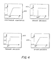
- FIG. 4, shows, in graphical form, various embodiments of adaptive amplification factor s used in practicing the present invention;
- FIG. 5 is a schematic block diagram of an embodiment of
adaptive factor generator 100 ofsystem 10 shown in FIG. 1 which provides a continuous adaption adaptive amplification factor s; and - FIG. 6 is a schematic block diagram of an embodiment of
adaptive factor generator 100 ofsystem 10 shown in FIG. 1 which provides a binary adaption adaptive amplification factor s. - Referring now to FIG. 1, there is shown at 10 a schematic block diagram of a system for practicing the method of this invention for processing and enhancing image data corresponding to a plurality of pixel values that may be derived from a two-dimensional photosensitvie array. A plurality of image defining pixel values may be provided by a two-dimensional photosensitive array comprising a high resolution charge coupled device (CCD) or a charge injection device (CID) which receives image scene light in a well-known manner by way of an objective lens and shutter (not shown). The image sensing array comprises a plurality of image sensing elements or pixels preferably arranged in a two-dimensional area array wherein each image sensing pixel disposed at a point (i,j) converts the incident image defining scene light rays into a corresponding analog signal value. As is well known in the art, a typical array of such image sensing pixels are arranged in columns and rows.
- As shown in FIG. 1,
selector 15 of image processing and enhancingsystem 10 obtains a pixel value to be enhanced, x(i,j), from array ofpixel values 5 and applies it as input to: (a)adder 20; (b)adder 50; (c) low-pass filter 30; and (d) squarer 40. Further,selector 15 obtains a predetermined, select group of pixel values which are disposed in the vicinity of the pixel value to be enhanced, i.e., "filter support" W, fromarray 5 and applies it as input to low-pass filter 30 and squarer 40. If "filter support" group W includes the pixel to be enhanced, then that value will also be applied as input to low-pass filter 30 and squarer 40. It should be understood that although FIG. 1 showsselector 15 applying the same "filter support" group W to low-pass filter 30 and to squarer 40, this does not limit the present invention. In fact, in certain embodiments, a first "filter support" group W may be applied as input to low-pass filter 30 and a second "filter support" group V may be applied as input to squarer 40. - The output from low-
pass filter 30 is applied as input to squarer 80 and to a subtracting input ofadder 50. The output fromadder 50 represents the high frequency component of the pixel value at point (i,j) and it is applied as input tomultiplier 60. Predetermined amplification factor c, also known as sharpening constant c, is also applied as input tomultiplier 60 and the output frommultiplier 60 is the amplified high frequency component at point (i,j). The amplified high frequency component at point (i,j) is applied as input tomultiplier 110. - The output from squarer 40, which output represents the squared pixel value input thereto, is applied as input to low-
pass filter 70. Note that low-pass filter 70 need not be the same type of low-pass filter as low-pass filter 30. The output from low-pass filter 70 is applied as input to adder 90. The output from squarer 80 represents the squared low frequency component of the pixel value at point (i,j) and it is applied as input to a subtracting input ofadder 90. The output fromadder 90 represents the variance of the pixel values at point (i,j) and it is applied as input toadaptive factor generator 100. - Predetermined noise power estimate e², also referred to below as the noise variance, is also applied as input to
adaptive factor generator 100 and, in response,adaptive factor generator 100 produces adaptive amplification factor s as output, which output varies from 0 to 1.0. Adaptive amplification factor s is applied as input tomultiplier 110. - The output from
multiplier 110 represents the amplified and scaled high frequency component of the pixel value to be enhanced and it is applied as input to adder 20.Adder 20 adds the amplified and scaled high frequency component of the pixel value to be enhanced to the pixel value to be enhanced to provide the sharpened image output pixel value y(i,j) in accordance with the present invention. - Referring now to the flowchart of FIG. 2, the image enhancing process of the present invention will be explained in detail. A first pixel value x(i,j) to be enhanced is selected from a two-dimensional area array of an image (block 200, FIG. 2). Then, a predetermined, select group of pixel values which are disposed in the vicinity of the pixel value to be enhanced, i.e., "filter support" W, are selected from the array (block 210, FIG. 2).
- FIG. 3 shows a plan view of a portion of an area array of photosensitive pixels for various embodiments of "filter support" W, i.e., embodiments 300 - 370, used in practicing the present invention. As shown in FIG. 3, N denotes the number of pixels in each embodiment. An appropriate pixel configuration of a "filter support" for use in a particular application may be determined by trial and error. However, in determining such an appropriate pixel configuration, it is important to note that the selection of an appropriate pixel configuration will depend on image resolution of the image and "viewing distance" from the image. This is because a "filter support" is used to provide a "blurred image" in the vicinity of the pixel value to be enhanced and the issue as to whether or not an image is blurred depends on image resolution and viewing distance. For example, the region covered by a "filter support" should expand, i.e., include more pixels, as either the resolution of the image or the viewing distance from the image increases, and vice versa, to provide an appropriate blur. This can be understood qualitatively from the fact that as the resolution of an image increases, one needs to take in more of the image to provide a "blurred image."
- Referring back to the flowchart of FIG. 2, in the next step, a "blurred" pixel value z(i,j) is obtained from "filter support" W in accordance with the following (block 220, FIG. 2):


- In one embodiment of the present invention, coefficients hkl are chosen to have a uniform value for each of the N pixels in "filter support" W and this is described as follows:
hkl = 1/N for all k and l in W.
As a result, in this embodiment:
- Next, a predetermined, select group of pixels which are disposed in the vicinity of the pixel value to be enhanced, i.e., "filter support" V, are selected from the array (block 230, FIG. 2). Next, a generalized statistical variance of pixel values in "filter support" V is obtained (block 240, FIG. 2). In specific embodiments of the present invention, the generalized statistical variance, v(i,j), is generated by low-pass filtering the "filter support" group V. Although, "filter support" V and the low-pass filter for this step do not have to be the same as "filter support" W and the low-pass filter of the step shown in
block 220, respectively, in a preferred embodiment of the inventive method they are all the same. As a result:

- Advantageously, when N is a power of 2, z(i,j) and v(i,j) can be generated by an add-shift operation. This is advantageous because z(i,j) and v(i,j) can then be determined rapidly when the present invention is implemented in a processor wherein multiplications take longer to perform than additions.
- Next, the high frequency component of the pixel value to be enhanced is determined as follows (block 250, FIG. 2):
x(i,j) - z(i,j) - Next, an adaptive amplification factor s which varies from 0 to 1 is determined using the generalized statistical variance of pixel values around the pixel value to be enhanced, v(i,j), and an estimate of the image noise power of the system (block 260, FIG. 2).
- Next, the high frequency component of the pixel value to be enhanced is sharpened by use of a predetermined sharpening constant c and the adaptive amplification factor s as follows (block 270, FIG. 2):
c*s[x(i,j) - z(i,j)] - Next, the output enhanced pixel value y(i,j) is determined by adding the input pixel value to be enhanced to the sharpened high frequency component of the pixel value to be enhanced (block 280, FIG. 2):
y(i,j) = x(i,j) + c*s[x(i,j) - z(i,j)] - Finally, the next succeeding pixel value to be enhanced is selected and one returns to the step set forth in
block 210 of FIG. 2 until substantially all pixel values are enhanced (block 290, FIG. 2). - It should be clear to those of ordinary skill in the art that the present invention is not limited to sharpening an entire image and, in fact, it may be applied to sharpen a portion of an image. In such a case, the step of selecting the next succeeding pixel shown in
block 290 of FIG. 2 would be appropriately altered. - FIG. 4 shows, in graphical form, embodiments 400 - 430 of adaptive amplification factor s which are used in practicing the present invention. For example, adaptive amplification factor s for
curve 400 corresponds to a continuous adaption method, adaptive amplification factor s forcurve 410 corresponds to a binary adaption method, adaptive amplification factor s forcurve 420 corresponds to a ternary adaption method, and adaptive amplification factor s forcurve 430 corresponds to an M-ary adaption method. In particular, in one embodiment of the inventive method, adaptive amplification s forcurve 400 is given by:
s = 1 - e²/max[v(i,j),e²]
where e² is an estimate of the noise power in the input image, referred to as the noise variance, and v(i,j) is a generalized statistical variance of a select group of pixel values surrounding the pixel value to be enhanced, i.e., point (i,j). - FIG. 5 is a schematic block diagram of an embodiment of
adaptive factor generator 100 ofsystem 10 shown in FIG. 1 which provides adaptive amplification factor s indicated bycontinuous adaption curve 400 of FIG. 4. The output fromadder 90 of FIG. 1 represents the variance of the pixel values at point (i,j), i.e., v(i,j), and it is applied as input todecision maker 500 along with predetermined noise power estimate e², where e² is a measure of the noise in the image produced by the imaging system.Decision maker 500 determines which of v(i,j) and e² is the larger and the larger value is applied as input toinverter 510 to form the reciprocal of the larger value. The output frominverter 510 is applied as input tomultiplier 520 along with e². The output frommultiplier 520 is applied as input to a subtracting input ofadder 530 and "1" is applied as input to an adding input ofadder 530. Finally, the output fromadder 530 is adaptive amplification factor s. - As one can readily appreciate from the following equation:
y(i,j) = x(i,j) + c*s[x(i,j) - z(i,j)]
sharpening constant c controls the degree of sharpening in the output image. For example, when c = 0 there is no sharpening whereas edges and details in the image become sharper as the value of c increases. However, if the value of c becomes too large, overshoots and undershoots near edges become too large and, therefore, visible. We have determined that a desirable range for c is 0 < c < 2.0, however, the optimum value of c for sharpness enhancement varies with a specific image as well as with a specific imaging system. - For the continuous adaption method, the enhanced pixel value y(i,j) comprises the sum of the input pixel value and the product of its high frequency component, x(i,j) - z(i,j), with the adaptive amplification factor s and the sharpening constant c. For pixel values where the local variance v(i,j) is much greater than the noise variance e², i.e., when v(i,j) » e², the product c*s reduces to c and the output y(i,j) is given by:
y(i,j) = x(i,j) + c[x(i,j) - z(i,j)]
which is the conventional sharpening method called unsharp masking. - On the other hand, for pixel values where v(i,j) is close to or less than e², the output y(i,j) is given by:
y(i,j) = x(i,j)
i.e., the pixel values are unchanged in the output. - Thus, in accordance with the continuous adaption method, sharpening takes place only when the filtering point belongs to an edge whose presence results in a large value of v(i,j). Thus, in effect, the noise variance e² controls what is sharpened and what is not. Since the noise variance is usually constant and invariant for a given imaging system, it can be determined, in accordance with methods well known to those of ordinary skill in the art, from an examination of flat areas of typical input images. For example, the imaging system can be exposed to uniform light and the noise variance can be determined in accordance with methods well known to those of ordinary skill in the art.
- Note that the accuracy with which the noise variation e² is determined is not critical to the performance of embodiments of the present invention, i.e., the present invention provides a robust and reliable method, because v(i,j) in the vicinity of an edge is usually much greater than e². As a result, even if one uses an estimate for e² which is very much different from the actual noise variance, details in the input image will not be lost.
- FIG. 6 is a schematic block diagram of an embodiment of
adaptive factor generator 100 ofsystem 10 shown in FIG. 1 which provides an adaptive amplification factor s indicated bybinary adaption curve 410 of FIG. 4. This embodiment of the present invention is useful when the noise in an input image is not severe, i.e., in those instances when v(i,j) obtained in the vicinity of an edge is always much greater than the noise variance over a flat area. In such instances, the computational operations required to provide the adaptive amplification factor described above in accordance with the continuous adaption method can be saved by using a binary adaption method, also referred to as a "hard-limiting" adaption method. In this method, one obtains a sharp transition between sharpening and no-sharpening instead of the smooth transition provided by the continuous adaption method. Specifically, in the "hard-limiting" adaption method:
s = 1 if v(i,j) > ne²
or
s = 0 if v(i,j) ≦ ne² (12)
where n defines a multiple of the noise variance as a threshold value. In this embodiment, the output is given by:
y(i,j) = x(i,j) + c[x(i,j) - z(i,j)] if v(i,j) > ne²
or
y(i,j) = x(i,j) if v(i,j) ≦ ne² - In FIG. 6, the output from
adder 90 of FIG. 1, i.e., v(i,j), is applied as input todecision maker 600 along with predetermined noise power estimate e².Decision maker 600 determines which of v and ne² is the larger, where n is a predetermined number. The output fromdecision maker 600 is adaptive amplification factor s; where s = 1 if v is larger than ne², and s = 0 otherwise. - A further embodiment of the present invention which is based on the principles of the embodiment shown in FIG. 6 may be fabricated wherein the output from
decision maker 600 comprises an "ON" or "OFF" signal which is applied as input to a switch which replacesmultiplier 110 in FIG. 1. In this further embodiment, when the switch is "ON" the pixel value is sharpened by its high frequency component whereas when the switch is "OFF" it is not. In addition, it should be clear to those of ordinary skill in the art as to how the ternary and M-ary adaptions indicated bycurves decision maker 500 of FIG. 5. - Further embodiments of the present invention comprise the use of a look-up table to determine complex adaptive amplification factors.
- Embodiments of the present invention may be used for sharpening color images. For example, a first embodiment of the present invention for sharpening a color image comprises the step of separating the color image into, for example, three primary colors in accordance with methods which are well known to those of ordinary skill in the art. Then, the next steps comprise applying embodiments of the present invention which were described above to sharpen each color primary image separately. Finally, the sharpened color primary images are combined to form the output sharpened color image in accordance with methods which are well known to those of ordinary skill in the art.
- A second embodiment of the present invention for sharpening a color image comprises the step of transforming the color image into color coordinates which are comprised of a luminance component. For example, the luminance pixel value x(i,j) of an input color image array may be generated as follows:
x(i,j) = 0.299R(i,j) + 0.597G(i,j) + 0.114B(i,j)
where R(i,j), G(i,j), and B(i,j) are the red, green and blue primaries, respectively. Then, the next steps comprise applying embodiments of the present invention which were described above to sharpen the luminance pixel values. Next, the sharpened luminance pixel values are transformed back into the original color coordinates in accordance with methods which are well known to those of ordinary skill in the art. Finally, the sharpened color coordinate images are combined to form the output sharpened color image in accordance with methods which are well known to those of ordinary skill in the art. The second embodiment wherein only the luminance is sharpened is advantageous because it reduces the number of operations required to sharpen an image to approximately one-third of the number required for the first embodiment. - A third embodiment of the present invention for sharpening a color image comprises the step of transforming the color image into a color coordinate which is comprised of a luminance component as was done for the second embodiment described above. Then, the next steps comprise applying embodiments of the present invention which were described above to sharpen the luminance pixel values. Finally, each color primary signal is scaled by the ratio between the output and the input luminance signal which is given by:
f = max[y(i,j),0]/max[x(i,j),1]
where the use of the "max" function ensures the positiveness of the pixel values. As a consequence of this, the sharpened color primaries are determined in accordance with the following:
R′(i,j) = f*R(i,j)
G′(i,j) = f*G(i,j)
B′(i,j) = f*B(i,j) - Finally, the sharpened color primary images are combined to form the output sharpened color image in accordance with methods which are well known to those of ordinary skill in the art. This embodiment is advantageous because the saturation of colors in the input image is preserved in the output image.
- Other embodiments of the invention, including additions, subtractions, deletions and other modifications of the preferred disclosed embodiments of the invention will be obvious to those skilled in the art and are within the scope of the following claims. For example, it should be clear to those of ordinary skill in the art that embodiments of the present invention are not limited to the use of a single noise estimate e² for adaptive sharpening. Further, the sharpening of color images is not restricted to use of red, green and blue as the color primaries or to the luminance function described above.
Claims (28)
selecting a pixel value to be enhanced from an array of pixel values;
sampling a select group of pixel values surrounding the pixel value to be enhanced from the array of pixel values;
determining a "blurred image" pixel value for the select group of pixel values surrounding the pixel value to be enhanced;
adaptively changing the pixel value to be enhanced to an enhanced value as a function of the "blurred image" pixel value and a predetermined property of the pixel values in a further select group of pixel values surrounding the pixel value to be enhanced; and
selecting a succeeding pixel value to be enhanced from said array of pixel values and applying the above steps to provide an enhanced pixel value for the succeeding pixel value so selected until substantially all the pixel values from at least a portion of the array of pixel values are changed to enhanced values.
determining the high frequency component of the pixel value to be enhanced as a function of the "blurred image" and
adaptively changing the pixel value to be enhanced as a function of the high frequency component and the predetermined property of the pixel values in the further select group of pixel values.
adaptively amplifying the high frequency component as a function of the variance, a predetermined estimate of the noise power, and a predetermined sharpening amount and
adding the adaptively amplified high frequency component to the pixel value to be enhanced.
separating the color image data into a predetermined number of select color coordinate two-dimensional arrays of pixel values;
performing the following steps for each of the predetermined number of select color coordinate two-dimensional arrays of pixel values: selecting a pixel value to be enhanced from an array of pixel values;
sampling a select group of pixel values surrounding the pixel value to be enhanced from the array of pixel values;
determining a "blurred image" pixel value for the select group of pixel values surrounding the pixel value to be enhanced;
adaptively changing the pixel value to be enhanced to an enhanced value as a function of the "blurred image" luminance pixel value and the variance of the pixel values in a further select group of pixel values surrounding the pixel value to be enhanced; and
selecting a succeeding pixel value to be enhanced from said array of pixel values and applying the above steps to provide an enhanced pixel value for the succeeding pixel value so selected until substantially all the pixel values from at least a portion of the array of pixel values are changed to enhanced values; and converting the predetermined number of enhanced predetermined color coordinate two-dimensional arrays of pixel values into enhanced color image data.
converting the color image data into a two-dimensional array of luminance pixel values;
performing the following steps for the two-dimensional array of luminance pixel values: selecting a luminance pixel value to be enhanced from an array of luminance pixel values;
sampling a select group of luminance pixel values surrounding the luminance pixel value to be enhanced from the array of luminance pixel values;
determining a "blurred image" luminance pixel value for the select group of luminance pixel values surrounding the luminance pixel value to be enhanced;
adaptively changing the luminance pixel value to be enhanced to an enhanced value as a function of the "blurred image" luminance pixel value and the variance of the luminance pixel values in a further select group of luminance pixel values surrounding the luminance pixel value to be enhanced; and
selecting a succeeding luminance pixel value to be enhanced from said array of luminance pixel values and applying the above steps to provide an enhanced luminance pixel value for the succeeding luminance pixel value so selected until substantially all the luminance pixel values from at least a portion of the array of luminance pixel values are changed to enhanced values; and converting the two-dimensional array of luminance pixel values into enhanced color image data.
converting the color image data into a two-dimensional array of luminance pixel values and into a predetermined number of select color coordinate two-dimensional arrays of pixel values;
performing the following steps for the two-dimensional array of luminance pixel values: selecting a luminance pixel value to be enhanced from an array of luminance pixel values;
sampling a select group of luminance pixel values surrounding the luminance pixel value to be enhanced from the array of luminance pixel values;
determining a "blurred image" luminance pixel value for the select group of luminance pixel values surrounding the luminance pixel value to be enhanced;
adaptively changing the luminance pixel value to be enhanced to an enhanced value as a function of the "blurred image" luminance pixel value and the variance of the luminance pixel values in a further select group of luminance pixel values surrounding the luminance pixel value to be enhanced; and
selecting a succeeding luminance pixel value to be enhanced from said array of luminance pixel values and applying the above steps to provide an enhanced luminance pixel value for the succeeding luminance pixel value so selected until substantially all the luminance pixel values from at least a portion of the array of luminance pixel values are changed to enhanced values; converting the predetermined number of color coordinate two-dimensional arrays of pixel values into enhanced predetermined color coordinate two-dimensional arrays by multiplying the pixel value of each of the predetermined number of color coordinate two-dimensional arrays by a weighting factor which is a function of the enhanced luminance pixel value and the luminance pixel value; and
converting the predetermined number of enhanced predetermined color coordinate two-dimensional arrays of pixel values into enhanced color image data.
Applications Claiming Priority (2)
| Application Number | Priority Date | Filing Date | Title |
|---|---|---|---|
| US351930 | 1989-05-15 | ||
| US07/351,930 US5038388A (en) | 1989-05-15 | 1989-05-15 | Method for adaptively sharpening electronic images |
Publications (3)
| Publication Number | Publication Date |
|---|---|
| EP0398861A2 true EP0398861A2 (en) | 1990-11-22 |
| EP0398861A3 EP0398861A3 (en) | 1992-10-07 |
| EP0398861B1 EP0398861B1 (en) | 1996-10-23 |
Family
ID=23383043
Family Applications (1)
| Application Number | Title | Priority Date | Filing Date |
|---|---|---|---|
| EP90890131A Expired - Lifetime EP0398861B1 (en) | 1989-05-15 | 1990-04-30 | Method for adaptively sharpening electronic images |
Country Status (9)
| Country | Link |
|---|---|
| US (1) | US5038388A (en) |
| EP (1) | EP0398861B1 (en) |
| JP (1) | JP3070860B2 (en) |
| AT (1) | ATE144636T1 (en) |
| AU (1) | AU619971B2 (en) |
| CA (1) | CA2013750C (en) |
| DE (2) | DE69028946T2 (en) |
| ES (1) | ES2020797A4 (en) |
| GR (1) | GR900300197T1 (en) |
Cited By (19)
| Publication number | Priority date | Publication date | Assignee | Title |
|---|---|---|---|---|
| EP0531904A2 (en) * | 1991-09-10 | 1993-03-17 | Eastman Kodak Company | Method and apparatus for spatially variant filtering |
| WO1993017394A1 (en) * | 1992-02-26 | 1993-09-02 | Cymbolic Sciences International Ltd. | Method and apparatus for adaptively interpolating a digital image |
| EP0624848A2 (en) * | 1993-05-04 | 1994-11-17 | Eastman Kodak Company | A technique for the detection and removal of local defects in digital continuous-tone images |
| EP0698990A1 (en) * | 1994-08-25 | 1996-02-28 | STMicroelectronics S.r.l. | Fuzzy device for image noise reduction |
| EP0849706A2 (en) * | 1996-12-18 | 1998-06-24 | Xerox Corporation | Adaptive noise removal for video images |
| WO1998059320A1 (en) * | 1997-06-21 | 1998-12-30 | Raytheon Company | System and method for local area image processing |
| WO2001020551A1 (en) * | 1999-09-13 | 2001-03-22 | Intel Corporation | Compression edge adaptive video and image sharpening and scaling |
| WO2001057798A2 (en) * | 2000-02-03 | 2001-08-09 | Applied Science Fiction | Match blur system and method |
| EP1134969A1 (en) * | 2000-03-13 | 2001-09-19 | Koninklijke Philips Electronics N.V. | Picture improvement |
| US6526179B2 (en) | 1999-04-14 | 2003-02-25 | Intel Corporation | Compression sensitive sharpening |
| EP1320071A2 (en) * | 2001-12-12 | 2003-06-18 | Samsung Electronics Co., Ltd. | Image enhancement with under- and overshoot suppression |
| EP1341124A1 (en) * | 2002-02-27 | 2003-09-03 | Eastman Kodak Company | Method for sharpening a digital image with signal to noise estimation |
| WO2003100723A1 (en) * | 2002-05-24 | 2003-12-04 | Koninklijke Philips Electronics N.V. | Unit for and method of calculating a sharpened edge |
| EP1396816A2 (en) * | 2002-09-05 | 2004-03-10 | Eastman Kodak Company | Method for sharpening a digital image |
| EP1439490A2 (en) * | 2003-01-16 | 2004-07-21 | Samsung Electronics Co., Ltd. | Shoot suppression in image Enhancement |
| WO2005117414A1 (en) * | 2004-05-25 | 2005-12-08 | Koninklijke Philips Electronics N.V. | Method and system for enhancing the sharpness of a video signal. |
| WO2006015058A2 (en) * | 2004-07-30 | 2006-02-09 | Hewlett-Packard Development Company, L.P. | Adjusting pixels by desired gains and factors |
| EP4345739A1 (en) * | 2022-09-30 | 2024-04-03 | Imagination Technologies Limited | Adaptive sharpening for blocks of pixels |
| GB2623070A (en) * | 2022-09-30 | 2024-04-10 | Imagination Tech Ltd | Adaptive sharpening for blocks of pixels |
Families Citing this family (60)
| Publication number | Priority date | Publication date | Assignee | Title |
|---|---|---|---|---|
| US5182778A (en) * | 1990-08-31 | 1993-01-26 | Eastman Kodak Company | Dot-matrix video enhancement for optical character recognition |
| US5271064A (en) * | 1991-06-14 | 1993-12-14 | University Of Cincinnati | Apparatus and method for smoothing regions and enhancing edges in gray scale images |
| US5524162A (en) * | 1991-07-22 | 1996-06-04 | Levien; Raphael L. | Method and apparatus for adaptive sharpening of images |
| US5294989A (en) * | 1991-09-17 | 1994-03-15 | Moore Color, Inc. | Saturable smoothing grid for image processing |
| EP0563846A1 (en) * | 1992-03-30 | 1993-10-06 | Matsushita Electric Industrial Co., Ltd. | Dynamic peaking aperture correction for use with a CCD camera |
| US5343309A (en) * | 1992-08-12 | 1994-08-30 | Xerox Corporation | Image processing system and method employing adaptive filtering to provide improved reconstruction of continuous tone images from halftone images including those without a screen structure |
| US5631979A (en) * | 1992-10-26 | 1997-05-20 | Eastman Kodak Company | Pixel value estimation technique using non-linear prediction |
| CA2128389C (en) * | 1993-10-15 | 1999-05-11 | Lawrence Patrick O'gorman | Method of reducing document size for digital display |
| US5710839A (en) * | 1994-04-20 | 1998-01-20 | Eastman Kodak Company | Method and apparatus for obscuring features of an image |
| US5933540A (en) * | 1995-05-11 | 1999-08-03 | General Electric Company | Filter system and method for efficiently suppressing noise and improving edge definition in a digitized image |
| KR100206319B1 (en) * | 1995-12-13 | 1999-07-01 | 윤종용 | Local contrast improving method and apparatus of a video signal |
| GB9600293D0 (en) * | 1996-01-08 | 1996-03-13 | Digi Media Vision Ltd | Improvements in or relating to noise reduction |
| JP3999270B2 (en) * | 1996-08-26 | 2007-10-31 | コーニンクレッカ フィリップス エレクトロニクス エヌ ヴィ | Sharpness control |
| KR100234316B1 (en) * | 1997-04-04 | 1999-12-15 | 윤종용 | Signal adaptive filter for reducing ringing noise and signal adaptive filering method thereof |
| US5867606A (en) * | 1997-08-12 | 1999-02-02 | Hewlett-Packard Company | Apparatus and method for determining the appropriate amount of sharpening for an image |
| US6118906A (en) * | 1998-02-03 | 2000-09-12 | Eastman Kodak Company | Sharpening system adjusted for measured noise of photofinishing images |
| US6801339B1 (en) * | 1998-03-26 | 2004-10-05 | Fuji Photo Film Co., Ltd. | Image processing method and apparatus |
| US6233069B1 (en) * | 1998-05-28 | 2001-05-15 | Eastman Kodak Company | Digital photofinishing system including film under exposure gamma, scene balance, contrast normalization, and image sharpening digital image processing |
| US6614474B1 (en) * | 1998-08-27 | 2003-09-02 | Polycom, Inc. | Electronic pan tilt zoom video camera with adaptive edge sharpening filter |
| RU2150146C1 (en) | 1998-09-03 | 2000-05-27 | Семенченко Михаил Григорьевич | Method for image processing |
| US6424730B1 (en) | 1998-11-03 | 2002-07-23 | Eastman Kodak Company | Medical image enhancement method for hardcopy prints |
| JP4147647B2 (en) * | 1998-11-09 | 2008-09-10 | ソニー株式会社 | Data processing apparatus, data processing method, and recording medium |
| JP4517409B2 (en) * | 1998-11-09 | 2010-08-04 | ソニー株式会社 | Data processing apparatus and data processing method |
| US6421468B1 (en) * | 1999-01-06 | 2002-07-16 | Seiko Epson Corporation | Method and apparatus for sharpening an image by scaling elements of a frequency-domain representation |
| JP4164712B2 (en) * | 1999-02-09 | 2008-10-15 | ソニー株式会社 | Data processing apparatus and data processing method |
| JP4344964B2 (en) * | 1999-06-01 | 2009-10-14 | ソニー株式会社 | Image processing apparatus and image processing method |
| US6804408B1 (en) | 1999-12-22 | 2004-10-12 | Eastman Kodak Company | Method for enhancing a digital image with noise-dependent control of texture |
| JP2003529294A (en) * | 2000-03-24 | 2003-09-30 | コーニンクレッカ フィリップス エレクトロニクス エヌ ヴィ | Electronic circuit and method for enhancing an image |
| US6856704B1 (en) | 2000-09-13 | 2005-02-15 | Eastman Kodak Company | Method for enhancing a digital image based upon pixel color |
| JP4149126B2 (en) * | 2000-12-05 | 2008-09-10 | ジーイー・メディカル・システムズ・グローバル・テクノロジー・カンパニー・エルエルシー | Image processing method, image processing apparatus, and image photographing apparatus |
| US7177481B2 (en) * | 2000-12-19 | 2007-02-13 | Konica Corporation | Multiresolution unsharp image processing apparatus |
| US6950561B2 (en) * | 2001-01-10 | 2005-09-27 | Koninklijke Philips Electronics N.V. | Method and system for sharpness enhancement for coded video |
| JP2002314843A (en) * | 2001-04-11 | 2002-10-25 | Sony Corp | Apparatus and method for highlighting edge as well as video camera |
| JP4503441B2 (en) * | 2002-11-06 | 2010-07-14 | ディジビジョン・インコーポレイテッド | System and method for improving the quality of multidimensional images |
| CN100525380C (en) * | 2003-07-07 | 2009-08-05 | 致伸科技股份有限公司 | Method of image processing using fuzzy screening method |
| US7391933B2 (en) * | 2003-10-30 | 2008-06-24 | Samsung Electronics Co., Ltd. | Method and apparatus for image interpolation based on adaptive polyphase filters |
| US20060222258A1 (en) * | 2005-04-05 | 2006-10-05 | Samsung Electronics Co., Ltd. | Image restoration with gain control and shoot suppression |
| WO2007043460A1 (en) * | 2005-10-12 | 2007-04-19 | Matsushita Electric Industrial Co., Ltd. | Visual processing apparatus, display apparatus, visual processing method, program and integrated circuit |
| KR100800888B1 (en) * | 2005-12-08 | 2008-02-04 | 연세대학교 산학협력단 | Method for using Signal Denoising Algorithm Based on Pattern Information |
| US7643698B2 (en) * | 2005-12-22 | 2010-01-05 | Apple Inc. | Image sharpening using diffusion |
| JP4240324B2 (en) * | 2006-01-16 | 2009-03-18 | ソニー株式会社 | Image processing apparatus, image processing method, program for image processing method, and recording medium recording program for image processing method |
| TW200733720A (en) * | 2006-02-24 | 2007-09-01 | Pixart Imaging Inc | Digital image processing method and the device thereof |
| JP4523926B2 (en) * | 2006-04-05 | 2010-08-11 | 富士通株式会社 | Image processing apparatus, image processing program, and image processing method |
| CN102438097B (en) | 2006-04-19 | 2015-06-03 | 松下电器(美国)知识产权公司 | Visual processing device, visual processing method |
| CN102238314B (en) * | 2006-04-28 | 2013-06-12 | 松下电器产业株式会社 | Visual processing apparatus, visual processing method, program, recording medium, display, and integrated circuit |
| TWI314301B (en) * | 2006-06-30 | 2009-09-01 | Primax Electronics Ltd | Adaptive image sharpening method |
| TWI330036B (en) * | 2006-10-27 | 2010-09-01 | Quanta Comp Inc | Apparatus for sharpening an image, and method thereof |
| US7952647B2 (en) * | 2006-12-27 | 2011-05-31 | Intel Corporation | Method and apparatus of content adaptive detailing filtering for digital pictures |
| US7769241B2 (en) * | 2007-01-09 | 2010-08-03 | Eastman Kodak Company | Method of sharpening using panchromatic pixels |
| US8594451B2 (en) * | 2007-03-30 | 2013-11-26 | Omnivision Technologies, Inc. | Edge mapping incorporating panchromatic pixels |
| US20090237530A1 (en) * | 2008-03-20 | 2009-09-24 | Ilia Ovsiannikov | Methods and apparatuses for sharpening images |
| US8456545B2 (en) * | 2009-05-08 | 2013-06-04 | Qualcomm Incorporated | Systems, methods, and apparatus for generation of reinforcement pattern and systems, methods, and apparatus for artifact evaluation |
| US8223230B2 (en) * | 2009-05-08 | 2012-07-17 | Qualcomm Incorporated | Systems, methods, and apparatus for camera tuning and systems, methods, and apparatus for reference pattern generation |
| US8849057B2 (en) * | 2011-05-19 | 2014-09-30 | Foveon, Inc. | Methods for digital image sharpening with noise amplification avoidance |
| SE536510C2 (en) * | 2012-02-21 | 2014-01-14 | Flir Systems Ab | Imaging method for detail enhancement and noise reduction |
| CN103514583B (en) * | 2012-06-30 | 2016-08-24 | 华为技术有限公司 | Image sharpening method and equipment |
| US9646366B2 (en) * | 2012-11-30 | 2017-05-09 | Change Healthcare Llc | Method and apparatus for enhancing medical images |
| US10559073B2 (en) * | 2016-03-23 | 2020-02-11 | Intel Corporation | Motion adaptive stream processing for temporal noise reduction |
| WO2020097836A1 (en) * | 2018-11-15 | 2020-05-22 | 深圳市欢太科技有限公司 | Image processing method and apparatus, and computer device and storage medium |
| TWI776733B (en) | 2021-11-12 | 2022-09-01 | 國立臺灣大學 | Data processing method for rapidly suppressing high-frequency noises in digitized image |
Citations (3)
| Publication number | Priority date | Publication date | Assignee | Title |
|---|---|---|---|---|
| EP0153167A2 (en) * | 1984-02-17 | 1985-08-28 | Minnesota Mining And Manufacturing Company | Method of image enhancement by raster scanning |
| EP0280412A2 (en) * | 1987-02-27 | 1988-08-31 | Picker International, Inc. | Image processing |
| US4783840A (en) * | 1987-12-04 | 1988-11-08 | Polaroid Corporation | Method for enhancing image data by noise reduction or sharpening |
Family Cites Families (11)
| Publication number | Priority date | Publication date | Assignee | Title |
|---|---|---|---|---|
| US4072928A (en) * | 1975-10-10 | 1978-02-07 | Sangamo Weston, Inc. | Industrial system for inspecting and identifying workpieces |
| US4215414A (en) * | 1978-03-07 | 1980-07-29 | Hughes Aircraft Company | Pseudogaussian video output processing for digital display |
| GB2046051B (en) * | 1979-03-29 | 1983-01-26 | Philips Electronic Associated | Real time histogram modification system for image processing |
| US4334244A (en) * | 1980-07-28 | 1982-06-08 | Magnavox Government And Industrial Electronics Company | Adaptive image enhancement system |
| DE3110222C2 (en) * | 1981-03-17 | 1985-06-20 | Dr.-Ing. Rudolf Hell Gmbh, 2300 Kiel | Process for partial smoothing retouching in electronic color image reproduction |
| US4517607A (en) * | 1981-11-09 | 1985-05-14 | Ricoh Company, Ltd. | Method of and apparatus for compensating image in image reproduction system |
| US4532548A (en) * | 1983-01-27 | 1985-07-30 | Hughes Aircraft Company | Resolution enhancement and zoom |
| US4633504A (en) * | 1984-06-28 | 1986-12-30 | Kla Instruments Corporation | Automatic photomask inspection system having image enhancement means |
| US4683496A (en) * | 1985-08-23 | 1987-07-28 | The Analytic Sciences Corporation | System for and method of enhancing images using multiband information |
| US4941190A (en) * | 1988-07-15 | 1990-07-10 | Minnesota Mining And Manufacturing Company | Method and system for enhancement of a digitized image |
| US4945502A (en) * | 1988-12-27 | 1990-07-31 | Eastman Kodak Company | Digital image sharpening method using SVD block transform |
-
1989
- 1989-05-15 US US07/351,930 patent/US5038388A/en not_active Expired - Lifetime
-
1990
- 1990-04-03 CA CA002013750A patent/CA2013750C/en not_active Expired - Fee Related
- 1990-04-12 AU AU53244/90A patent/AU619971B2/en not_active Ceased
- 1990-04-30 DE DE69028946T patent/DE69028946T2/en not_active Expired - Fee Related
- 1990-04-30 DE DE199090890131T patent/DE398861T1/en active Pending
- 1990-04-30 AT AT90890131T patent/ATE144636T1/en not_active IP Right Cessation
- 1990-04-30 ES ES90890131T patent/ES2020797A4/en active Pending
- 1990-04-30 EP EP90890131A patent/EP0398861B1/en not_active Expired - Lifetime
- 1990-05-14 JP JP2123970A patent/JP3070860B2/en not_active Expired - Lifetime
-
1991
- 1991-10-10 GR GR90300197T patent/GR900300197T1/en unknown
Patent Citations (3)
| Publication number | Priority date | Publication date | Assignee | Title |
|---|---|---|---|---|
| EP0153167A2 (en) * | 1984-02-17 | 1985-08-28 | Minnesota Mining And Manufacturing Company | Method of image enhancement by raster scanning |
| EP0280412A2 (en) * | 1987-02-27 | 1988-08-31 | Picker International, Inc. | Image processing |
| US4783840A (en) * | 1987-12-04 | 1988-11-08 | Polaroid Corporation | Method for enhancing image data by noise reduction or sharpening |
Non-Patent Citations (2)
| Title |
|---|
| IEEE TRANSACTIONS ON CIRCUITS AND SYSTEMS vol. 35, no. 8, August 1988, NEW YORK pages 1048 - 1055; WOO-JIN SONG ET AL: 'Edge-preserving noise filtering based on adaptive windowing' * |
| PROCEEDINGS OF THE EIGHTH INTERNATIONAL CONFERENCE ON PATTERN RECOGNITION October 1986, PARIS pages 981 - 983; WANG DEMIN ET AL: 'A weighted averaging method for image smoothing' * |
Cited By (35)
| Publication number | Priority date | Publication date | Assignee | Title |
|---|---|---|---|---|
| EP0531904A2 (en) * | 1991-09-10 | 1993-03-17 | Eastman Kodak Company | Method and apparatus for spatially variant filtering |
| EP0531904A3 (en) * | 1991-09-10 | 1993-10-06 | Eastman Kodak Company | Method and apparatus for spatially variant filtering |
| WO1993017394A1 (en) * | 1992-02-26 | 1993-09-02 | Cymbolic Sciences International Ltd. | Method and apparatus for adaptively interpolating a digital image |
| EP0624848A2 (en) * | 1993-05-04 | 1994-11-17 | Eastman Kodak Company | A technique for the detection and removal of local defects in digital continuous-tone images |
| EP0624848A3 (en) * | 1993-05-04 | 1994-11-30 | Eastman Kodak Company | A technique for the detection and removal of local defects in digital continuous-tone images |
| EP0698990A1 (en) * | 1994-08-25 | 1996-02-28 | STMicroelectronics S.r.l. | Fuzzy device for image noise reduction |
| US5748796A (en) * | 1994-08-25 | 1998-05-05 | Sgs-Thomson Microelectronics S.R.L. | Fuzzy logic device for image noise reduction |
| EP0849706A3 (en) * | 1996-12-18 | 1998-11-11 | Xerox Corporation | Adaptive noise removal for video images |
| EP0849706A2 (en) * | 1996-12-18 | 1998-06-24 | Xerox Corporation | Adaptive noise removal for video images |
| WO1998059320A1 (en) * | 1997-06-21 | 1998-12-30 | Raytheon Company | System and method for local area image processing |
| US6007052A (en) * | 1997-06-21 | 1999-12-28 | Raytheon Company | System and method for local area image processing |
| US6526179B2 (en) | 1999-04-14 | 2003-02-25 | Intel Corporation | Compression sensitive sharpening |
| WO2001020551A1 (en) * | 1999-09-13 | 2001-03-22 | Intel Corporation | Compression edge adaptive video and image sharpening and scaling |
| GB2370175B (en) * | 1999-09-13 | 2003-12-03 | Intel Corp | Compression edge adaptive video and image sharpening and scaling |
| US6330372B1 (en) | 1999-09-13 | 2001-12-11 | Intel Corporation | Compression edge adaptive video and image sharpening and scaling |
| GB2370175A (en) * | 1999-09-13 | 2002-06-19 | Intel Corp | Compression edge adaptive video and image sharpening and scaling |
| WO2001057798A3 (en) * | 2000-02-03 | 2002-10-17 | Applied Science Fiction | Match blur system and method |
| WO2001057798A2 (en) * | 2000-02-03 | 2001-08-09 | Applied Science Fiction | Match blur system and method |
| EP1134969A1 (en) * | 2000-03-13 | 2001-09-19 | Koninklijke Philips Electronics N.V. | Picture improvement |
| EP1320071A2 (en) * | 2001-12-12 | 2003-06-18 | Samsung Electronics Co., Ltd. | Image enhancement with under- and overshoot suppression |
| EP1320071A3 (en) * | 2001-12-12 | 2008-02-27 | Samsung Electronics Co., Ltd. | Image enhancement with under- and overshoot suppression |
| US6965702B2 (en) | 2002-02-27 | 2005-11-15 | Eastman Kodak Company | Method for sharpening a digital image with signal to noise estimation |
| EP1341124A1 (en) * | 2002-02-27 | 2003-09-03 | Eastman Kodak Company | Method for sharpening a digital image with signal to noise estimation |
| WO2003100723A1 (en) * | 2002-05-24 | 2003-12-04 | Koninklijke Philips Electronics N.V. | Unit for and method of calculating a sharpened edge |
| EP1396816A3 (en) * | 2002-09-05 | 2004-10-06 | Eastman Kodak Company | Method for sharpening a digital image |
| US7228004B2 (en) | 2002-09-05 | 2007-06-05 | Eastman Kodak Company | Method for sharpening a digital image |
| EP1396816A2 (en) * | 2002-09-05 | 2004-03-10 | Eastman Kodak Company | Method for sharpening a digital image |
| EP1439490A2 (en) * | 2003-01-16 | 2004-07-21 | Samsung Electronics Co., Ltd. | Shoot suppression in image Enhancement |
| EP1439490A3 (en) * | 2003-01-16 | 2008-06-04 | Samsung Electronics Co., Ltd. | Shoot suppression in image Enhancement |
| WO2005117414A1 (en) * | 2004-05-25 | 2005-12-08 | Koninklijke Philips Electronics N.V. | Method and system for enhancing the sharpness of a video signal. |
| WO2006015058A2 (en) * | 2004-07-30 | 2006-02-09 | Hewlett-Packard Development Company, L.P. | Adjusting pixels by desired gains and factors |
| WO2006015058A3 (en) * | 2004-07-30 | 2006-03-16 | Hewlett Packard Development Co | Adjusting pixels by desired gains and factors |
| US7426314B2 (en) | 2004-07-30 | 2008-09-16 | Hewlett-Packard Development Company, L.P. | Adjusting pixels by desired gains and factors |
| EP4345739A1 (en) * | 2022-09-30 | 2024-04-03 | Imagination Technologies Limited | Adaptive sharpening for blocks of pixels |
| GB2623070A (en) * | 2022-09-30 | 2024-04-10 | Imagination Tech Ltd | Adaptive sharpening for blocks of pixels |
Also Published As
| Publication number | Publication date |
|---|---|
| EP0398861B1 (en) | 1996-10-23 |
| JP3070860B2 (en) | 2000-07-31 |
| AU5324490A (en) | 1990-11-15 |
| JPH034680A (en) | 1991-01-10 |
| GR900300197T1 (en) | 1991-10-10 |
| US5038388A (en) | 1991-08-06 |
| AU619971B2 (en) | 1992-02-06 |
| ES2020797A4 (en) | 1991-10-01 |
| CA2013750C (en) | 2000-12-12 |
| DE69028946T2 (en) | 1997-04-17 |
| EP0398861A3 (en) | 1992-10-07 |
| ATE144636T1 (en) | 1996-11-15 |
| DE398861T1 (en) | 1991-03-21 |
| CA2013750A1 (en) | 1990-11-15 |
| DE69028946D1 (en) | 1996-11-28 |
Similar Documents
| Publication | Publication Date | Title |
|---|---|---|
| US5038388A (en) | Method for adaptively sharpening electronic images | |
| Russo | A method for estimation and filtering of Gaussian noise in images | |
| US8155468B2 (en) | Image processing method and apparatus | |
| EP1174824B1 (en) | Noise reduction method utilizing color information, apparatus, and program for digital image processing | |
| US7280703B2 (en) | Method of spatially filtering a digital image using chrominance information | |
| US6373992B1 (en) | Method and apparatus for image processing | |
| US6724942B1 (en) | Image processing method and system | |
| JP4460839B2 (en) | Digital image sharpening device | |
| US20020176113A1 (en) | Dynamic image correction and imaging systems | |
| EP0971315A2 (en) | Automatic tone adjustment by contrast gain-control on edges | |
| JP2001005960A (en) | Method and device for processing image | |
| US7672528B2 (en) | Method of processing an image to form an image pyramid | |
| JPH0795409A (en) | Space filter device | |
| JPH0766977A (en) | Picture processing unit | |
| JPH0568147B2 (en) | ||
| US7110044B2 (en) | Image detail enhancement system | |
| EP0114961B1 (en) | Nonlinear filtering of gray scale video images | |
| WO2004036499A1 (en) | A method for interpolation and sharpening of images | |
| EP0851665A2 (en) | Improved sharpening filter for images | |
| EP0851666B1 (en) | Sharpening filter for images with automatic adaption to image type | |
| US20060039622A1 (en) | Sharpness enhancement | |
| US20020159652A1 (en) | Image processing apparatus, image processing method, and program product | |
| Russo | Piecewise linear model-based image enhancement | |
| JPH04321379A (en) | Adaptive picture emphasis circuit | |
| RU2383924C2 (en) | Method for adaptive increase of sharpness of digital photographs during printing |
Legal Events
| Date | Code | Title | Description |
|---|---|---|---|
| PUAI | Public reference made under article 153(3) epc to a published international application that has entered the european phase |
Free format text: ORIGINAL CODE: 0009012 |
|
| AK | Designated contracting states |
Kind code of ref document: A2 Designated state(s): AT BE CH DE DK ES FR GB GR IT LI LU NL SE |
|
| TCAT | At: translation of patent claims filed | ||
| ITCL | It: translation for ep claims filed |
Representative=s name: RICCARDI SERGIO & CO. |
|
| TCNL | Nl: translation of patent claims filed | ||
| DET | De: translation of patent claims | ||
| EL | Fr: translation of claims filed | ||
| PUAL | Search report despatched |
Free format text: ORIGINAL CODE: 0009013 |
|
| AK | Designated contracting states |
Kind code of ref document: A3 Designated state(s): AT BE CH DE DK ES FR GB GR IT LI LU NL SE |
|
| 17P | Request for examination filed |
Effective date: 19930325 |
|
| 17Q | First examination report despatched |
Effective date: 19950123 |
|
| GRAG | Despatch of communication of intention to grant |
Free format text: ORIGINAL CODE: EPIDOS AGRA |
|
| GRAH | Despatch of communication of intention to grant a patent |
Free format text: ORIGINAL CODE: EPIDOS IGRA |
|
| GRAH | Despatch of communication of intention to grant a patent |
Free format text: ORIGINAL CODE: EPIDOS IGRA |
|
| GRAA | (expected) grant |
Free format text: ORIGINAL CODE: 0009210 |
|
| AK | Designated contracting states |
Kind code of ref document: B1 Designated state(s): AT BE CH DE DK ES FR GB GR IT LI LU NL SE |
|
| PG25 | Lapsed in a contracting state [announced via postgrant information from national office to epo] |
Ref country code: NL Free format text: LAPSE BECAUSE OF FAILURE TO SUBMIT A TRANSLATION OF THE DESCRIPTION OR TO PAY THE FEE WITHIN THE PRESCRIBED TIME-LIMIT Effective date: 19961023 Ref country code: LI Effective date: 19961023 Ref country code: GR Free format text: LAPSE BECAUSE OF FAILURE TO SUBMIT A TRANSLATION OF THE DESCRIPTION OR TO PAY THE FEE WITHIN THE PRESCRIBED TIME-LIMIT Effective date: 19961023 Ref country code: DK Effective date: 19961023 Ref country code: CH Effective date: 19961023 Ref country code: BE Effective date: 19961023 Ref country code: AT Effective date: 19961023 |
|
| REF | Corresponds to: |
Ref document number: 144636 Country of ref document: AT Date of ref document: 19961115 Kind code of ref document: T |
|
| ET | Fr: translation filed | ||
| REF | Corresponds to: |
Ref document number: 69028946 Country of ref document: DE Date of ref document: 19961128 |
|
| ITF | It: translation for a ep patent filed |
Owner name: UFFICIO BREVETTI RICCARDI & C. |
|
| PG25 | Lapsed in a contracting state [announced via postgrant information from national office to epo] |
Ref country code: SE Effective date: 19970123 |
|
| PG25 | Lapsed in a contracting state [announced via postgrant information from national office to epo] |
Ref country code: ES Free format text: LAPSE BECAUSE OF FAILURE TO SUBMIT A TRANSLATION OF THE DESCRIPTION OR TO PAY THE FEE WITHIN THE PRESCRIBED TIME-LIMIT Effective date: 19970220 |
|
| NLV1 | Nl: lapsed or annulled due to failure to fulfill the requirements of art. 29p and 29m of the patents act | ||
| PG25 | Lapsed in a contracting state [announced via postgrant information from national office to epo] |
Ref country code: LU Free format text: LAPSE BECAUSE OF NON-PAYMENT OF DUE FEES Effective date: 19970430 |
|
| REG | Reference to a national code |
Ref country code: CH Ref legal event code: PL |
|
| PLBE | No opposition filed within time limit |
Free format text: ORIGINAL CODE: 0009261 |
|
| STAA | Information on the status of an ep patent application or granted ep patent |
Free format text: STATUS: NO OPPOSITION FILED WITHIN TIME LIMIT |
|
| 26N | No opposition filed | ||
| PGFP | Annual fee paid to national office [announced via postgrant information from national office to epo] |
Ref country code: FR Payment date: 20000313 Year of fee payment: 11 |
|
| PGFP | Annual fee paid to national office [announced via postgrant information from national office to epo] |
Ref country code: GB Payment date: 20000321 Year of fee payment: 11 |
|
| PGFP | Annual fee paid to national office [announced via postgrant information from national office to epo] |
Ref country code: DE Payment date: 20000324 Year of fee payment: 11 |
|
| PG25 | Lapsed in a contracting state [announced via postgrant information from national office to epo] |
Ref country code: GB Free format text: LAPSE BECAUSE OF NON-PAYMENT OF DUE FEES Effective date: 20010430 Ref country code: FR Free format text: THE PATENT HAS BEEN ANNULLED BY A DECISION OF A NATIONAL AUTHORITY Effective date: 20010430 |
|
| GBPC | Gb: european patent ceased through non-payment of renewal fee |
Effective date: 20010430 |
|
| PG25 | Lapsed in a contracting state [announced via postgrant information from national office to epo] |
Ref country code: DE Free format text: LAPSE BECAUSE OF NON-PAYMENT OF DUE FEES Effective date: 20020201 |
|
| REG | Reference to a national code |
Ref country code: FR Ref legal event code: ST |
|
| PG25 | Lapsed in a contracting state [announced via postgrant information from national office to epo] |
Ref country code: IT Free format text: LAPSE BECAUSE OF NON-PAYMENT OF DUE FEES;WARNING: LAPSES OF ITALIAN PATENTS WITH EFFECTIVE DATE BEFORE 2007 MAY HAVE OCCURRED AT ANY TIME BEFORE 2007. THE CORRECT EFFECTIVE DATE MAY BE DIFFERENT FROM THE ONE RECORDED. Effective date: 20050430 |