EP0393389A2 - Staged shooting pot for injection molding - Google Patents
Staged shooting pot for injection molding Download PDFInfo
- Publication number
- EP0393389A2 EP0393389A2 EP90105808A EP90105808A EP0393389A2 EP 0393389 A2 EP0393389 A2 EP 0393389A2 EP 90105808 A EP90105808 A EP 90105808A EP 90105808 A EP90105808 A EP 90105808A EP 0393389 A2 EP0393389 A2 EP 0393389A2
- Authority
- EP
- European Patent Office
- Prior art keywords
- shooting pot
- mold cavity
- thermoplastic material
- hot runner
- injection
- Prior art date
- Legal status (The legal status is an assumption and is not a legal conclusion. Google has not performed a legal analysis and makes no representation as to the accuracy of the status listed.)
- Granted
Links
- 238000001746 injection moulding Methods 0.000 title claims abstract description 11
- 239000012815 thermoplastic material Substances 0.000 claims abstract description 53
- 238000000034 method Methods 0.000 claims abstract description 12
- 238000002347 injection Methods 0.000 claims description 55
- 239000007924 injection Substances 0.000 claims description 55
- 229920005989 resin Polymers 0.000 claims description 51
- 239000011347 resin Substances 0.000 claims description 51
- 230000035611 feeding Effects 0.000 description 14
- 239000012530 fluid Substances 0.000 description 6
- 238000012856 packing Methods 0.000 description 6
- 238000000465 moulding Methods 0.000 description 4
- 238000010276 construction Methods 0.000 description 2
- 238000012986 modification Methods 0.000 description 2
- 230000004048 modification Effects 0.000 description 2
- 229920005992 thermoplastic resin Polymers 0.000 description 2
- 230000015572 biosynthetic process Effects 0.000 description 1
- 238000013461 design Methods 0.000 description 1
- 238000010438 heat treatment Methods 0.000 description 1
- 238000012423 maintenance Methods 0.000 description 1
- 239000000463 material Substances 0.000 description 1
- 238000012545 processing Methods 0.000 description 1
Images


Classifications
-
- B—PERFORMING OPERATIONS; TRANSPORTING
- B29—WORKING OF PLASTICS; WORKING OF SUBSTANCES IN A PLASTIC STATE IN GENERAL
- B29C—SHAPING OR JOINING OF PLASTICS; SHAPING OF MATERIAL IN A PLASTIC STATE, NOT OTHERWISE PROVIDED FOR; AFTER-TREATMENT OF THE SHAPED PRODUCTS, e.g. REPAIRING
- B29C45/00—Injection moulding, i.e. forcing the required volume of moulding material through a nozzle into a closed mould; Apparatus therefor
- B29C45/16—Making multilayered or multicoloured articles
-
- B—PERFORMING OPERATIONS; TRANSPORTING
- B29—WORKING OF PLASTICS; WORKING OF SUBSTANCES IN A PLASTIC STATE IN GENERAL
- B29C—SHAPING OR JOINING OF PLASTICS; SHAPING OF MATERIAL IN A PLASTIC STATE, NOT OTHERWISE PROVIDED FOR; AFTER-TREATMENT OF THE SHAPED PRODUCTS, e.g. REPAIRING
- B29C45/00—Injection moulding, i.e. forcing the required volume of moulding material through a nozzle into a closed mould; Apparatus therefor
- B29C45/02—Transfer moulding, i.e. transferring the required volume of moulding material by a plunger from a "shot" cavity into a mould cavity
-
- B—PERFORMING OPERATIONS; TRANSPORTING
- B29—WORKING OF PLASTICS; WORKING OF SUBSTANCES IN A PLASTIC STATE IN GENERAL
- B29C—SHAPING OR JOINING OF PLASTICS; SHAPING OF MATERIAL IN A PLASTIC STATE, NOT OTHERWISE PROVIDED FOR; AFTER-TREATMENT OF THE SHAPED PRODUCTS, e.g. REPAIRING
- B29C45/00—Injection moulding, i.e. forcing the required volume of moulding material through a nozzle into a closed mould; Apparatus therefor
- B29C45/17—Component parts, details or accessories; Auxiliary operations
- B29C45/46—Means for plasticising or homogenising the moulding material or forcing it into the mould
- B29C45/53—Means for plasticising or homogenising the moulding material or forcing it into the mould using injection ram or piston
- B29C45/54—Means for plasticising or homogenising the moulding material or forcing it into the mould using injection ram or piston and plasticising screw
-
- B—PERFORMING OPERATIONS; TRANSPORTING
- B29—WORKING OF PLASTICS; WORKING OF SUBSTANCES IN A PLASTIC STATE IN GENERAL
- B29C—SHAPING OR JOINING OF PLASTICS; SHAPING OF MATERIAL IN A PLASTIC STATE, NOT OTHERWISE PROVIDED FOR; AFTER-TREATMENT OF THE SHAPED PRODUCTS, e.g. REPAIRING
- B29C45/00—Injection moulding, i.e. forcing the required volume of moulding material through a nozzle into a closed mould; Apparatus therefor
- B29C45/17—Component parts, details or accessories; Auxiliary operations
- B29C45/46—Means for plasticising or homogenising the moulding material or forcing it into the mould
- B29C45/57—Exerting after-pressure on the moulding material
-
- B—PERFORMING OPERATIONS; TRANSPORTING
- B29—WORKING OF PLASTICS; WORKING OF SUBSTANCES IN A PLASTIC STATE IN GENERAL
- B29C—SHAPING OR JOINING OF PLASTICS; SHAPING OF MATERIAL IN A PLASTIC STATE, NOT OTHERWISE PROVIDED FOR; AFTER-TREATMENT OF THE SHAPED PRODUCTS, e.g. REPAIRING
- B29C45/00—Injection moulding, i.e. forcing the required volume of moulding material through a nozzle into a closed mould; Apparatus therefor
- B29C45/17—Component parts, details or accessories; Auxiliary operations
- B29C45/26—Moulds
- B29C45/27—Sprue channels ; Runner channels or runner nozzles
- B29C45/2725—Manifolds
Abstract
Description
- The present invention relates to injection molding and particularly to the precise control or metering of thermoplastic material to one or more mold cavities.
- The use of control units such as shooting pots to introduce thermoplastic resin into mold cavities in an injection molding system is well known. In such arrangements a primary resin source feeds the reservoir of a shooting pot and the shooting pot in turn is operated to feed a measured or metered quantity of thermoplastic material into the mold cavity.
- It is also known to supply thermoplastic material to a multicavity mold where the cavities of the mold are fed by a hot runner system and where the hot runner system includes a plurality of shooting pots, with at least one each individual to each molding cavity. That is, a source of thermoplastic material leads to the hot runner system which in turn feeds the respective mold cavities wherein a shooting pot or metering means is provided for each mold cavity for controlling precisely the introduction of a shot of resin to the mold cavity. U.S. Patents 4,717,324 and 4,775,308 teach the coinjection of a plurality of thermoplastic materials to mold an article having a layered wall structure using thermoplastic materials having different optimum processing temperatures including the maintenance of the optimum temperatures in flow paths individual to each material from its source to a mold cavity. These patents show shooting pots used in conjunction with the formation of the layered wall structure and multicavity molding. However, these disclosures involve the use of shooting pots to individually meter the amount of the first feeding of a first resin and the first feeding of a second resin into each cavity of a multicavity mold. In all cases, however, the final feeding and packing of the cavity is achieved by pressurizing the extruder or injection unit used to supply the final feeding resin to all the cavities in the mold. Thus, the hot runner supply channel system must be carefully balanced between the extruder or injection unit and each cavity gate or cavity orifice of the multicavity mold. In case of a large number of mold cavities, such as 32 or 48, this becomes quite impractical to achieve.
- Accordingly, it is a principal object of the present invention to provide an injection molding method and apparatus for feeding a supply of thermoplastic material to a mold cavity from a shooting pot which can effectively eliminate the need for packing by the extruder or injection unit.
- It is a further object of the present invention to provide a method and apparatus as aforesaid which is suitable for use with an injection molding apparatus including a large number of cavities.
- Further objects and advantages of the present invention will appear hereinbelow.
- In accordance with the present invention, the foregoing objects and advantages can be readily achieved.
- The method of the present invention comprises a method for injection molding which comprises: feeding a supply of thermoplastic material to a shooting pot from a supply of thermoplastic material via a hot runner system; delivering a first charge of thermoplastic material from the shooting pot to a mold cavity; and delivering a second charge of thermoplastic material from the shooting pot to the mold cavity. The shooting pot maintains injection pressure or packing pressure on the mold cavity to pack or complete filling of the mold cavity and overcome shrinkage. Preferably also, a multicavity molding system is provided with a plurality of shooting pots, each individual to each mold cavity.
- The injection molding apparatus of the present invention comprises: at least one mold cavity; a hot runner system for supplying thermoplastic material to said mold cavity; supply means for supplying said thermoplastic material to said hot runner system; a shooting pot operative to hold a given amount of thermoplastic material communicating with the hot runner system and supplied thereby; a first valve means between the supply means and the shooting pot, generally in the hot runner system, and a second valve means between the shooting pot and the mold cavity, both of said valve means being operative to permit and block flow of thermoplastic material; a first injection means communicating with said shooting pot for delivery of a first charge of thermoplastic material from said shooting pot to said mold cavity; and a second injection means communicating with said shooting pot for delivery of a second charge of thermoplastic material from the shooting pot to the mold cavity. The second injection means is provided with means for maintaining a supply of thermoplastic material from the shooting pot to the mold cavity in order to pack or fill the mold cavity and overcome shrinkage of thermoplastic material.
- In the preferred embodiment, a second hot runner system is provided for supplying a second thermoplastic material to the mold cavity, second supply means for supplying said second thermoplastic material to said second hot runner system, a second shooting pot operative to hold a given amount of the second thermoplastic material communicating with the second hot runner system and supplied thereby, a third and fourth valve means operative to permit and block flow of thermoplastic material, and a third injection means communicating with the second shooting pot for delivering a charge of the second thermoplastic material to the mold cavity.
- Preferably also a plurality of mold cavities are provided with one or more shooting pots individual to each mold cavity.
- Thus, in accordance with the present invention, it is not necessary for the supply means or extruder to make the final feeding. The final feeding of thermoplastic material to each mold cavity can be achieved by a shooting pot, e.g., the same shooting pot that made the first feeding. This obviates the need to provide a balanced hot runner system between the machine's extruder or injection unit and each cavity. Consequently, a simpler design is provided and complicated hot runner construction is eliminated. Moreover, in accordance with the present invention, it now becomes practical to construct multicavity molds exceeding 24 cavities.
- Further objects and advantages of the present invention will appear hereinbelow.
- The present invention will be more readily understandable from a consideration of the appended drawings wherein:
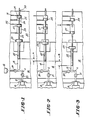
- Figure 1 is a schematic drawing showing the injection system of the present invention fully charged with a resin;
- Figure 2 is similar to Figure 1 showing the first stage injection having been completed;
- Figure 3 is similar to Figure 1 showing the second stage injection having been completed;
- Figure 4 shows a two stage shooting pot in combination with a single stage shooting pot for supplying at least two different resins to the same cavity; and
- Figure 5 is a schematic illustration of the system and method of the present invention for a four cavity mold accommodating two thermoplastic resins with each mold utilizing the system of Figure 4.
- Figures 1-3 show a representative embodiment of the present invention. For ease of understanding Figures 1-3 show a single mold cavity; however, it should be appreciated that a plurality of mold cavities may be fed by a single extruder with each mold cavity including at least one shooting pot associated therewith. Figure 1 shows the injection system fully charged, Figure 2 shows the first stage injection completed, and Figure 3 shows the second stage injection completed. Referring to Figure 1,
mold cavity 10 is supplied with thermoplastic material via hot runner system 11, leading from a source or supply means of thermoplastic material, such as extruder 12. Shooting pot orinjection cylinder 13 communicates with hot runner system 11 and is supplied thereby. Both the shootingpot 13 and hot runner system 11 are located inmanifold 14 which may be provided with appropriate heating means to maintain the resin in the hot runner system and in the shooting pot at an appropriate temperature, all in a customary manner. Injection nozzle 15 is provided leading from hot runner system 11 and communicating withmold cavity 10, also in a customary manner, including customary valve gate (not shown). - A first valve means 20 is provided in hot runner system 11 between
shooting pot 13 and supply means 12, and a second valve means 21 is provided in hot runner system 11 betweenmold cavity 10 andshooting pot 13, both of said valve means being operative to permit and block flow of thermoplastic material in the hot runner system. Figure 1 shows the first valve means 20 open to permit flow of resin from extruder 12 to shootingpot 13, and the second valve means closed to prevent flow of resin to themold cavity 10. -
Shooting pot 13 is filled from supply means 12 via hot runner system 11 withvalve 20 open andvalve 21 closed as shown in Figure 1. In the filled condition the shooting pot contains a volume equal to V₁ and V₂ which is equivalent to the first charge of resin to the mold cavity (V₁) plus the second charge of resin to the mold cavity (V₂). The shooting pot can be discharged to supply resin to the mold cavity via hot runner system 11 with first valve means 20 closed to block back-flow of resin and second valve means 21 open, as shown in Figures 2 and 3. Thus, as shown for example in Figure 2, first valve means 20 is closed to block flow of resin to the supply means and second valve means 21 is open to permit flow of resin tomold cavity 10. -
Shooting pot 13 includesinjection piston 22 actuated byinjection pad 23. A firststage injection piston 24 situated infirst injection cavity 25 in machine platen 30 (or alternately in mold base) operatesfirst injection rod 26, which in turn actuates a secondstage injection piston 27 situated insecond injection cavity 28. Thesecond stage piston 27 operates asecond injection rod 29 which in turn actuatespad 23. In the fully charged position shown in Figure 1,piston 22,pad 23 andpistons - A high pressure fluid is supplied to one side of first
stage injection piston 24 viasupply line 31 from a suitable pressure source (not shown) to advancepiston 24 androd 26. Rod 26 pushes againstsecond stage piston 27 androd 29 which in turn pushes againstpad 23. Piston 24 advances until it bottoms out at the end of its stroke against cylinder end ofcavity 25. Theshooting pot piston 22 has advanced a distance A and displaced a corresponding volume of resin V₁ intomold cavity 10 with the apparatus now in the position shown in Figure 2. - As shown in Figure 3, the second stage injection takes place after the first stage injection when a high pressure fluid is supplied to one side of second
stage injection piston 27 viasupply line 32 from a suitable pressure source (not shown) to further advancepiston 27. Piston 27 in turnfurther advances rod 29 which in turn advancespad 23 androd 22 to displace a corresponding volume of resin V₂ intomold cavity 10 via nozzle 15. Unlike the first stage, however,piston 27 does not bottom out at the cylinder end ofcavity 28, but continues to maintain hold pressure against the piston to continue to pressurize the resin and to continue to supply more resin to the mold cavity during the hold stage or packing stage of the cycle. As the resin in the mold cavity shrinks more resin is supplied thereto from the shooting pot via pressure maintained onpiston 27 to make up the shrinkage until the cycle is complete and the shooting pot piston has advanced a final distance B. Piston 27 may then bottom out against cylinder end ofcavity 28 as shown in Figure 3. - When the injection and hold stages of the cycle are complete valve means 21 is closed and
valve means 20 is opened and the shooting pot is recharged with resin. The incoming resin pushes back theshooting pot piston 22,pad 23 and associated first and second stage pistons until thefirst stage piston 24 contacts volume adjusting means 33 which adjusts the stroke of the first and second injection means and the volume charged in the shooting pot. This is shown in Figures 1-3 as an adjustable threaded rod against whichfirst piston 24 contacts; however, any suitable means to adjust the volume of the resin delivered in the first and second injection steps may be employed. Thus, a preset volume of resin is charged in the shooting pot because of the preset stroke ofpiston 24 and associated back position ofpiston 27. Hence, preset volume V₁ (first shot) can be discharged and a second volume V₂ can be discharged (second shot) to fill and pack out the part in the mold cavity. - The molded part is ejected from the mold cavity and the cycle is repeated.
- A particular application of the present invention is in the coinjection of multilayered articles, such as for example preforms. Figure 4 shows a preferred embodiment, wherein it should be appreciated that a plurality of mold cavities may be employed, with each mold cavity having two or more shooting pots associated therewith and with the entire system fed by at least two extruders (one for each resin).
- Figure 4 shows a mold hot runner system having two sets of shooting pots and associated pistons for moving them. The first resin system utilizes a system as shown in Figures 1-3 with like reference numerals employed for like components. The second resin system utilizes
hot runner system 50 communicating with a supply of second resin as from a suitable extruder and communicating withmold cavity 10 via nozzle 15.Second shooting pot 51 operative to hold a given amount of second resin communicates withhot runner system 50 and supplied thereby. Third and fourth valve means 58 and 59 are provided onhot runner system 50 operative to permit and block flow of the second thermoplastic material in the same manner as first and second valve means 20 and 21.Second shooting pot 51 is operated byinjection piston 52 actuated byinjection pad 53 which in turn is actuated bypiston 54 androd 55. Volume adjusting means 56 is provided associated withpiston 54 similar to volume adjusting means 33. High pressure fluid is supplied to one side ofpiston 54 viasupply line 57 from a suitable pressure source (not shown). - Thus, in operation, the shooting pots are charged with resin by closing valve means 21 and 58 and opening valve means 20 and 59 as shown in Figure 4 with the system fully charged. Valve means 20 and 59 are then closed to block the supply channels to the shooting pots. Valve means 21 is opened. High pressure fluid is supplied to
first shot piston 24 to displace first volume V₁ of first resin intomold cavity 10 via channel 11 and nozzle 15. - Valve means 21 is then closed, valve means 58 opened and high pressure fluid is supplied to
piston 54 for a first shot of a second resin to advancepiston 54 and its associatedshooting pot piston 52 to displace a preset volume V₂ of resin intomold cavity 10 viachannel 50 and nozzle 15. - Valve means 58 is then closed and valve means 21 opened again. High pressure fluid is supplied to
third shot piston 27 to displace itsshooting pot piston 22 for a second feeding of the first resin intomold cavity 10 via channel 11 and nozzle 15 until the mold cavity is filled.Piston 27 maintains hold pressure to fill and packmold cavity 10 as in Figures 1-3. - Valve means 21 is then closed and valve means 20 and 59 opened to recharge both shooting pots at the same time for the next cycle, the molded part is removed and the cycle repeated.
- The sequence described above with respect to Figure 4 is for sequential injection of three feedings of two resins which will form a five layered wall structure in the molded part. The final feeding of the first resin includes the packing or holding step to fill the mold and compensate for shrinkage.
- As indicated hereinabove, the present invention is particularly suitable to simultaneous molding of a plurality of parts, such as for example 16, 24, 32 or 48 parts. This is shown schematically in Figure 5 for four parts using two resins in a manner similar to Figure 4. In Figure 5, extruder A feeds the first resin shorn in solid lines and extruder B feeds the second resin shown in dashed lines.
Molds 110 are fed byhot runner systems 111 and 150 similar tohot runner systems 11 and 50 respectively. Shootingpots pots mold cavity 110 has an associated first shootingpot 113 for the first resin and associated second shootingpot 151 for the second resin. Appropriate valve means are provided in the hot runner systems in a manner after Figure 4. Thus, it can be readily seen that a plurality of mold cavities may be fed from a single extruder for each resin with one or more shooting pots associated with each mold cavity for feeding resin to the mold cavity including filling and packing thereof by the shooting pots. - It can be readily seen that the method and apparatus of the present invention achieves significant advantages. The shooting pot system achieves a staggered injection cycle including a metered first charge followed by a second charge from the same source individual to each mold cavity. This provides a balanced hot runner system between the machine's extruder or injection unit and each cavity and avoids the considerable complications heretofore involved in constructing large multicavity systems. The present invention is admirably suitable to co-injection and tri-injection molding in multicavity molds obviating complexities of construction and achieving simplified operating systems. Moreover, in view of the fact that all feeding to the mold cavity is handled by the shooting pots, it becomes simpler to control the temperature of each resin individually. This is a highly desirable goal and it is achieved readily and conveniently by the instant system.
- It is to be understood that the invention is not limited to the illustrations described and shown herein, which are deemed to be merely illustrative of the best modes of carrying out the invention, and which are susceptible of modification of form, size, arrangement of parts and details of operation. The invention rather is intended to encompass all such modifications which are within its spirit and scope as defined by the claims.
-
- 10 mold cavity
- 11 hot runner system
- 12 extruder
- 13 shooting pot
- 14 manifold
- 15 injection nozzle
- 20 first valve means
- 21 second valve means
- 22 injection piston
- 23 injection pad
- 24 first stage injection piston
- 25 first injection cavity
- 26 first injection rod
- 27 second stage injection piston
- 28 second stage injection cavity
- 29 second stage injection rod
- 30 machine platen
- 31 supply line
- 32 supply line
- 33 volumead justing means
- 50 hot runner system
- 51 second shooting pot
- 52 injection piston
- 53 injection pad
- 54 piston
- 55 rod
- 56 volume adjusting means
- 57 supply line
- 58 fourth valve means
- 59 third valve means
- 110 mold
- 111 hot runner system
- 113 shooting pot
- 150 hot runner system
- 151 shooting pot
Claims (12)
Priority Applications (1)
| Application Number | Priority Date | Filing Date | Title |
|---|---|---|---|
| AT90105808T ATE100372T1 (en) | 1989-04-19 | 1990-03-27 | STEPPED SHELL FOR INJECTION MOLDING. |
Applications Claiming Priority (2)
| Application Number | Priority Date | Filing Date | Title |
|---|---|---|---|
| US07/340,256 US4966545A (en) | 1989-04-19 | 1989-04-19 | Staged shooting pot for injection molding |
| US340256 | 1994-11-16 |
Publications (3)
| Publication Number | Publication Date |
|---|---|
| EP0393389A2 true EP0393389A2 (en) | 1990-10-24 |
| EP0393389A3 EP0393389A3 (en) | 1991-07-17 |
| EP0393389B1 EP0393389B1 (en) | 1994-01-19 |
Family
ID=23332556
Family Applications (1)
| Application Number | Title | Priority Date | Filing Date |
|---|---|---|---|
| EP90105808A Expired - Lifetime EP0393389B1 (en) | 1989-04-19 | 1990-03-27 | Staged shooting pot for injection molding |
Country Status (5)
| Country | Link |
|---|---|
| US (1) | US4966545A (en) |
| EP (1) | EP0393389B1 (en) |
| JP (1) | JPH0749209B2 (en) |
| AT (1) | ATE100372T1 (en) |
| DE (1) | DE69006079T2 (en) |
Cited By (7)
| Publication number | Priority date | Publication date | Assignee | Title |
|---|---|---|---|---|
| EP0824057A1 (en) * | 1996-08-10 | 1998-02-18 | Rudolf Görlich | Method and apparatus for manufacturing plastic injection moulded articles |
| EP0947303A2 (en) * | 1998-03-30 | 1999-10-06 | Husky Injection Molding Systems Ltd. | Shooting pot actuator for an injection molding machine |
| AT408087B (en) * | 1999-03-02 | 2001-08-27 | Engel Gmbh Maschbau | DEVICE FOR PRODUCING OBJECTS FROM THERMOPLASTIC PLASTIC |
| EP1426160A1 (en) * | 2002-12-03 | 2004-06-09 | Mold-Masters Limited | Hot runner co-injection nozzle |
| US7192268B2 (en) | 2002-09-18 | 2007-03-20 | Mold-Masters Limited | Metering device for a nozzle of a hot runner injection molding apparatus |
| EP1778452A1 (en) * | 2004-06-30 | 2007-05-02 | Husky Injection Molding Systems Ltd. | Injection molding machine shooting pot with integral check valve |
| WO2017083180A1 (en) | 2015-11-11 | 2017-05-18 | Husky Injection Molding Systems Ltd. | Shooting pot refill timing |
Families Citing this family (21)
| Publication number | Priority date | Publication date | Assignee | Title |
|---|---|---|---|---|
| JP3027619B2 (en) * | 1991-03-26 | 2000-04-04 | 株式会社日本製鋼所 | Injection molding method and apparatus |
| JP3268189B2 (en) * | 1996-01-19 | 2002-03-25 | 株式会社名機製作所 | Injection device needle valve opening adjustment mechanism |
| US5849236A (en) * | 1996-05-10 | 1998-12-15 | Siegel-Robert, Inc. | Method and apparatus for plastic injection molding flow control |
| US6106751A (en) * | 1998-03-18 | 2000-08-22 | The Regents Of The University Of California | Method for fabricating needles via conformal deposition in two-piece molds |
| US6241932B1 (en) | 1998-03-19 | 2001-06-05 | Husky Injection Molding Systems Ltd. | Method and system for reducing polymer degradation products in two stage injection molding machines |
| US6228309B1 (en) * | 1998-12-22 | 2001-05-08 | Husky Injection Molding Systems Ltd. | Method and apparatus for injection molding including valve stem positioning |
| US6276916B1 (en) | 1999-06-30 | 2001-08-21 | Husky Injection Molding Systems Ltd. | Failsafe shooting pot actuator for an injection molding machine |
| US6450798B1 (en) | 2000-02-04 | 2002-09-17 | Avaya Technology Corp. | Apparatus for multiple cavity injection molding |
| US6347934B1 (en) | 2000-05-10 | 2002-02-19 | E. Khashoggi Industries, Llc. | System for metering and delivering a moldable composition into a mold |
| US7175420B2 (en) | 2003-02-13 | 2007-02-13 | Mold-Masters Limited | Valve gated injection molding system with independent flow control |
| US7165968B2 (en) * | 2004-06-30 | 2007-01-23 | Husky Injection Molding Systems Ltd. | Apparatus and method for sealing injection unit and sprue |
| US7559756B2 (en) * | 2004-06-30 | 2009-07-14 | Husky Injection Molding Systems, Ltd. | Apparatus and method for actuation of injection molding shooting pots |
| US7291298B2 (en) * | 2004-07-09 | 2007-11-06 | Husky Injection Molding Systems Ltd. | Apparatus and method for injection molding shooting pot wedge feature |
| US7393479B2 (en) * | 2004-10-15 | 2008-07-01 | Husky Injection Molding Systems Ltd. | Injection molding three-way shut off valve |
| EP1844916B1 (en) * | 2006-04-12 | 2014-06-25 | ENGEL AUSTRIA GmbH | Device for expansion injection moulding |
| US7771190B2 (en) * | 2007-10-31 | 2010-08-10 | Husky Injection Molding Systems Ltd. | High pressure injection molding nozzle with low pressure manifold |
| US8007272B2 (en) * | 2007-10-31 | 2011-08-30 | Husky Injection Molding Systems Ltd. | Shooting pot for feeding multiple nozzles |
| CA2782963C (en) * | 2009-12-31 | 2015-03-24 | Husky Injection Molding Systems Ltd. | Mold-runner system having independently controllable shooting-pot assemblies |
| US8328546B2 (en) | 2010-06-29 | 2012-12-11 | Mold-Masters (2007) Limited | Auxiliary injection unit integrated in injection molding system |
| WO2012068681A1 (en) | 2010-11-24 | 2012-05-31 | Husky Injection Molding Systems Ltd. | Molding system including shooting-pot assembly and valve assembly in which hold pressure not provided by shooting pot assembly |
| PT3374146T (en) * | 2015-11-11 | 2021-01-04 | Husky Injection Molding Systems Ltd | Shooting pot plunger control |
Citations (5)
| Publication number | Priority date | Publication date | Assignee | Title |
|---|---|---|---|---|
| US2505540A (en) * | 1945-02-15 | 1950-04-25 | Goldhard Franz Karl | Injection molding apparatus |
| DE1554887A1 (en) * | 1965-04-10 | 1969-07-17 | Salzgitter Maschinen Ag | Device for driving the injection piston of injection molding machines |
| WO1981000231A1 (en) * | 1979-07-20 | 1981-02-05 | American Can Co | Apparatus for making a multi-layer injection blow molded container |
| US4717324A (en) * | 1986-05-12 | 1988-01-05 | Husky Injection Molding Systems, Inc. | Coinjection of hollow articles and preforms |
| US4734243A (en) * | 1985-07-25 | 1988-03-29 | Aisin Seiki Kabushiki Kaisha | Injection molding machine and method |
Family Cites Families (7)
| Publication number | Priority date | Publication date | Assignee | Title |
|---|---|---|---|---|
| US3840312A (en) * | 1973-04-11 | 1974-10-08 | Control Process Inc | Dynamic pressure control system |
| US4525134A (en) * | 1979-07-20 | 1985-06-25 | American Can Company | Apparatus for making a multi-layer injection blow molded container |
| JPS6164416A (en) * | 1984-09-06 | 1986-04-02 | Sony Corp | Injection forming method |
| JPH078517B2 (en) * | 1985-11-25 | 1995-02-01 | 松下電工株式会社 | Molding method for thick molded products |
| JPS62138222A (en) * | 1985-12-10 | 1987-06-22 | Mitsuboshi Belting Ltd | Method and device for injection molding of resin molded product |
| GB8616460D0 (en) * | 1986-07-05 | 1986-08-13 | Metal Box Plc | Manufacture of articles |
| JPH0615188B2 (en) * | 1986-12-29 | 1994-03-02 | 日精樹脂工業株式会社 | Injection molding method |
-
1989
- 1989-04-19 US US07/340,256 patent/US4966545A/en not_active Expired - Fee Related
-
1990
- 1990-03-27 DE DE90105808T patent/DE69006079T2/en not_active Expired - Fee Related
- 1990-03-27 AT AT90105808T patent/ATE100372T1/en not_active IP Right Cessation
- 1990-03-27 EP EP90105808A patent/EP0393389B1/en not_active Expired - Lifetime
- 1990-04-19 JP JP2104386A patent/JPH0749209B2/en not_active Expired - Lifetime
Patent Citations (5)
| Publication number | Priority date | Publication date | Assignee | Title |
|---|---|---|---|---|
| US2505540A (en) * | 1945-02-15 | 1950-04-25 | Goldhard Franz Karl | Injection molding apparatus |
| DE1554887A1 (en) * | 1965-04-10 | 1969-07-17 | Salzgitter Maschinen Ag | Device for driving the injection piston of injection molding machines |
| WO1981000231A1 (en) * | 1979-07-20 | 1981-02-05 | American Can Co | Apparatus for making a multi-layer injection blow molded container |
| US4734243A (en) * | 1985-07-25 | 1988-03-29 | Aisin Seiki Kabushiki Kaisha | Injection molding machine and method |
| US4717324A (en) * | 1986-05-12 | 1988-01-05 | Husky Injection Molding Systems, Inc. | Coinjection of hollow articles and preforms |
Cited By (19)
| Publication number | Priority date | Publication date | Assignee | Title |
|---|---|---|---|---|
| US6045740A (en) * | 1996-08-10 | 2000-04-04 | Guenther Heisskanaltechnik Gmbh | Process and device for manufacturing injection-molded parts from plastic material |
| EP0824057A1 (en) * | 1996-08-10 | 1998-02-18 | Rudolf Görlich | Method and apparatus for manufacturing plastic injection moulded articles |
| EP0947303A2 (en) * | 1998-03-30 | 1999-10-06 | Husky Injection Molding Systems Ltd. | Shooting pot actuator for an injection molding machine |
| EP0947303A3 (en) * | 1998-03-30 | 2001-08-16 | Husky Injection Molding Systems Ltd. | Shooting pot actuator for an injection molding machine |
| CN1103670C (en) * | 1998-03-30 | 2003-03-26 | 赫斯基注射模具系统有限公司 | Shooting pot actuator for injection molding machine |
| US6540496B1 (en) | 1998-03-30 | 2003-04-01 | Husky Injection Molding Systems Ltd. | Shooting pot actuator for an injection molding machine |
| CN1315630C (en) * | 1998-03-30 | 2007-05-16 | 赫斯基注射模具系统有限公司 | Injection moulding machine with actuator for spouting crucible |
| AT408087B (en) * | 1999-03-02 | 2001-08-27 | Engel Gmbh Maschbau | DEVICE FOR PRODUCING OBJECTS FROM THERMOPLASTIC PLASTIC |
| DE10009827C2 (en) * | 1999-03-02 | 2003-01-02 | Engel Gmbh Maschbau | Device for producing objects from thermoplastic material |
| US7192268B2 (en) | 2002-09-18 | 2007-03-20 | Mold-Masters Limited | Metering device for a nozzle of a hot runner injection molding apparatus |
| EP1426160A1 (en) * | 2002-12-03 | 2004-06-09 | Mold-Masters Limited | Hot runner co-injection nozzle |
| EP1762359A2 (en) * | 2002-12-03 | 2007-03-14 | Mold-Masters Limited | Hot runner co-injection nozzle |
| EP1762359A3 (en) * | 2002-12-03 | 2007-04-18 | Mold-Masters Limited | Hot runner co-injection nozzle |
| US7175419B2 (en) | 2002-12-03 | 2007-02-13 | Mold-Masters Limited | Hot runner co-injection nozzle |
| EP1778452A1 (en) * | 2004-06-30 | 2007-05-02 | Husky Injection Molding Systems Ltd. | Injection molding machine shooting pot with integral check valve |
| EP1778452A4 (en) * | 2004-06-30 | 2009-01-14 | Husky Injection Molding | Injection molding machine shooting pot with integral check valve |
| WO2017083180A1 (en) | 2015-11-11 | 2017-05-18 | Husky Injection Molding Systems Ltd. | Shooting pot refill timing |
| EP3374140A4 (en) * | 2015-11-11 | 2019-06-26 | Husky Injection Molding Systems Luxembourg IP Development S.à.r.l | Shooting pot refill timing |
| US11958224B2 (en) | 2015-11-11 | 2024-04-16 | Husky Injection Molding Systems Ltd. | Shooting pot refill timing |
Also Published As
| Publication number | Publication date |
|---|---|
| US4966545A (en) | 1990-10-30 |
| EP0393389A3 (en) | 1991-07-17 |
| EP0393389B1 (en) | 1994-01-19 |
| JPH02295715A (en) | 1990-12-06 |
| DE69006079D1 (en) | 1994-03-03 |
| DE69006079T2 (en) | 1994-05-05 |
| JPH0749209B2 (en) | 1995-05-31 |
| ATE100372T1 (en) | 1994-02-15 |
Similar Documents
| Publication | Publication Date | Title |
|---|---|---|
| EP0393389B1 (en) | Staged shooting pot for injection molding | |
| US4863369A (en) | Injection molding with shooting pots | |
| US5192555A (en) | Apparatus for molding plastic articles | |
| US5069840A (en) | Molding plastic articles | |
| AU618409B2 (en) | Coinjection of hollow articles and preforms | |
| CA2261487C (en) | Shooting pot actuator for an injection molding machine | |
| EP0512337B1 (en) | Shooting pot with combined valve and piston | |
| US7192268B2 (en) | Metering device for a nozzle of a hot runner injection molding apparatus | |
| EP1426160B1 (en) | Hot runner co-injection nozzle | |
| US5260012A (en) | Molding plastic articles | |
| US5833899A (en) | Method for the preparation of method articles by single and multi-layer compression and apparatus therefor | |
| US3516123A (en) | Injection molding machine | |
| EP1360056B1 (en) | Metering device for a plastics moulding machine | |
| US6821101B2 (en) | Injection unit for injection molding machines with continuously operating plasticizing unit | |
| CA2714344C (en) | Compression injection moulding method and device for preforms | |
| WO2012068681A1 (en) | Molding system including shooting-pot assembly and valve assembly in which hold pressure not provided by shooting pot assembly | |
| AU2002226560A1 (en) | Metering device for a plastics moulding machine |
Legal Events
| Date | Code | Title | Description |
|---|---|---|---|
| PUAI | Public reference made under article 153(3) epc to a published international application that has entered the european phase |
Free format text: ORIGINAL CODE: 0009012 |
|
| AK | Designated contracting states |
Kind code of ref document: A2 Designated state(s): AT BE CH DE DK ES FR GB GR IT LI LU NL SE |
|
| PUAL | Search report despatched |
Free format text: ORIGINAL CODE: 0009013 |
|
| AK | Designated contracting states |
Kind code of ref document: A3 Designated state(s): AT BE CH DE DK ES FR GB GR IT LI LU NL SE |
|
| RHK1 | Main classification (correction) |
Ipc: B29C 45/54 |
|
| 17P | Request for examination filed |
Effective date: 19911016 |
|
| 17Q | First examination report despatched |
Effective date: 19930316 |
|
| GRAA | (expected) grant |
Free format text: ORIGINAL CODE: 0009210 |
|
| AK | Designated contracting states |
Kind code of ref document: B1 Designated state(s): AT BE CH DE DK ES FR GB GR IT LI LU NL SE |
|
| PG25 | Lapsed in a contracting state [announced via postgrant information from national office to epo] |
Ref country code: IT Free format text: LAPSE BECAUSE OF FAILURE TO SUBMIT A TRANSLATION OF THE DESCRIPTION OR TO PAY THE FEE WITHIN THE PRE;WARNING: LAPSES OF ITALIAN PATENTS WITH EFFECTIVE DATE BEFORE 2007 MAY HAVE OCCURRED AT ANY TIME BEFORE 2007. THE CORRECT EFFECTIVE DATE MAY BE DIFFERENT FROM THE ONE RECORDED.SCRIBED TIME-LIMIT Effective date: 19940119 Ref country code: ES Free format text: THE PATENT HAS BEEN ANNULLED BY A DECISION OF A NATIONAL AUTHORITY Effective date: 19940119 Ref country code: NL Effective date: 19940119 Ref country code: DK Effective date: 19940119 Ref country code: SE Effective date: 19940119 Ref country code: BE Effective date: 19940119 Ref country code: GR Free format text: LAPSE BECAUSE OF FAILURE TO SUBMIT A TRANSLATION OF THE DESCRIPTION OR TO PAY THE FEE WITHIN THE PRESCRIBED TIME-LIMIT Effective date: 19940119 |
|
| REF | Corresponds to: |
Ref document number: 100372 Country of ref document: AT Date of ref document: 19940215 Kind code of ref document: T |
|
| REF | Corresponds to: |
Ref document number: 69006079 Country of ref document: DE Date of ref document: 19940303 |
|
| ET | Fr: translation filed | ||
| PG25 | Lapsed in a contracting state [announced via postgrant information from national office to epo] |
Ref country code: LU Free format text: LAPSE BECAUSE OF NON-PAYMENT OF DUE FEES Effective date: 19940331 |
|
| NLV1 | Nl: lapsed or annulled due to failure to fulfill the requirements of art. 29p and 29m of the patents act | ||
| PLBE | No opposition filed within time limit |
Free format text: ORIGINAL CODE: 0009261 |
|
| STAA | Information on the status of an ep patent application or granted ep patent |
Free format text: STATUS: NO OPPOSITION FILED WITHIN TIME LIMIT |
|
| 26N | No opposition filed | ||
| PGFP | Annual fee paid to national office [announced via postgrant information from national office to epo] |
Ref country code: FR Payment date: 19990309 Year of fee payment: 10 |
|
| PGFP | Annual fee paid to national office [announced via postgrant information from national office to epo] |
Ref country code: AT Payment date: 19990311 Year of fee payment: 10 |
|
| PGFP | Annual fee paid to national office [announced via postgrant information from national office to epo] |
Ref country code: CH Payment date: 19990329 Year of fee payment: 10 |
|
| PGFP | Annual fee paid to national office [announced via postgrant information from national office to epo] |
Ref country code: GB Payment date: 19990401 Year of fee payment: 10 |
|
| PGFP | Annual fee paid to national office [announced via postgrant information from national office to epo] |
Ref country code: DE Payment date: 19990406 Year of fee payment: 10 |
|
| PG25 | Lapsed in a contracting state [announced via postgrant information from national office to epo] |
Ref country code: GB Free format text: LAPSE BECAUSE OF NON-PAYMENT OF DUE FEES Effective date: 20000327 Ref country code: AT Free format text: LAPSE BECAUSE OF NON-PAYMENT OF DUE FEES Effective date: 20000327 |
|
| PG25 | Lapsed in a contracting state [announced via postgrant information from national office to epo] |
Ref country code: CH Free format text: LAPSE BECAUSE OF NON-PAYMENT OF DUE FEES Effective date: 20000331 Ref country code: LI Free format text: LAPSE BECAUSE OF NON-PAYMENT OF DUE FEES Effective date: 20000331 |
|
| GBPC | Gb: european patent ceased through non-payment of renewal fee |
Effective date: 20000327 |
|
| REG | Reference to a national code |
Ref country code: CH Ref legal event code: PL |
|
| PG25 | Lapsed in a contracting state [announced via postgrant information from national office to epo] |
Ref country code: FR Free format text: LAPSE BECAUSE OF NON-PAYMENT OF DUE FEES Effective date: 20001130 |
|
| REG | Reference to a national code |
Ref country code: FR Ref legal event code: ST |
|
| PG25 | Lapsed in a contracting state [announced via postgrant information from national office to epo] |
Ref country code: DE Free format text: LAPSE BECAUSE OF NON-PAYMENT OF DUE FEES Effective date: 20010103 |