EP0390342A2 - Coupling mechanism - Google Patents
Coupling mechanism Download PDFInfo
- Publication number
- EP0390342A2 EP0390342A2 EP19900302249 EP90302249A EP0390342A2 EP 0390342 A2 EP0390342 A2 EP 0390342A2 EP 19900302249 EP19900302249 EP 19900302249 EP 90302249 A EP90302249 A EP 90302249A EP 0390342 A2 EP0390342 A2 EP 0390342A2
- Authority
- EP
- European Patent Office
- Prior art keywords
- shank
- clamping
- tool
- probe
- axis
- Prior art date
- Legal status (The legal status is an assumption and is not a legal conclusion. Google has not performed a legal analysis and makes no representation as to the accuracy of the status listed.)
- Granted
Links
Images

Classifications
-
- B—PERFORMING OPERATIONS; TRANSPORTING
- B23—MACHINE TOOLS; METAL-WORKING NOT OTHERWISE PROVIDED FOR
- B23B—TURNING; BORING
- B23B31/00—Chucks; Expansion mandrels; Adaptations thereof for remote control
- B23B31/02—Chucks
- B23B31/36—Chucks with means for adjusting the chuck with respect to the working-spindle
-
- B—PERFORMING OPERATIONS; TRANSPORTING
- B23—MACHINE TOOLS; METAL-WORKING NOT OTHERWISE PROVIDED FOR
- B23B—TURNING; BORING
- B23B31/00—Chucks; Expansion mandrels; Adaptations thereof for remote control
- B23B31/02—Chucks
- B23B31/10—Chucks characterised by the retaining or gripping devices or their immediate operating means
- B23B31/107—Retention by laterally-acting detents, e.g. pins, screws, wedges; Retention by loose elements, e.g. balls
- B23B31/1075—Retention by screws
- B23B31/1077—Retention by screws acting on a floating pin
-
- Y—GENERAL TAGGING OF NEW TECHNOLOGICAL DEVELOPMENTS; GENERAL TAGGING OF CROSS-SECTIONAL TECHNOLOGIES SPANNING OVER SEVERAL SECTIONS OF THE IPC; TECHNICAL SUBJECTS COVERED BY FORMER USPC CROSS-REFERENCE ART COLLECTIONS [XRACs] AND DIGESTS
- Y10—TECHNICAL SUBJECTS COVERED BY FORMER USPC
- Y10T—TECHNICAL SUBJECTS COVERED BY FORMER US CLASSIFICATION
- Y10T279/00—Chucks or sockets
- Y10T279/14—Eccentric
-
- Y—GENERAL TAGGING OF NEW TECHNOLOGICAL DEVELOPMENTS; GENERAL TAGGING OF CROSS-SECTIONAL TECHNOLOGIES SPANNING OVER SEVERAL SECTIONS OF THE IPC; TECHNICAL SUBJECTS COVERED BY FORMER USPC CROSS-REFERENCE ART COLLECTIONS [XRACs] AND DIGESTS
- Y10—TECHNICAL SUBJECTS COVERED BY FORMER USPC
- Y10T—TECHNICAL SUBJECTS COVERED BY FORMER US CLASSIFICATION
- Y10T279/00—Chucks or sockets
- Y10T279/17—Socket type
- Y10T279/17761—Side detent
- Y10T279/17821—Set screw
-
- Y—GENERAL TAGGING OF NEW TECHNOLOGICAL DEVELOPMENTS; GENERAL TAGGING OF CROSS-SECTIONAL TECHNOLOGIES SPANNING OVER SEVERAL SECTIONS OF THE IPC; TECHNICAL SUBJECTS COVERED BY FORMER USPC CROSS-REFERENCE ART COLLECTIONS [XRACs] AND DIGESTS
- Y10—TECHNICAL SUBJECTS COVERED BY FORMER USPC
- Y10T—TECHNICAL SUBJECTS COVERED BY FORMER US CLASSIFICATION
- Y10T408/00—Cutting by use of rotating axially moving tool
- Y10T408/83—Tool-support with means to move Tool relative to tool-support
- Y10T408/85—Tool-support with means to move Tool relative to tool-support to move radially
- Y10T408/858—Moving means including wedge, screw or cam
- Y10T408/8598—Screw extending perpendicular to tool-axis
- Y10T408/85995—Screw extending perpendicular to tool-axis with tool-holding clamp and clamp actuator
-
- Y—GENERAL TAGGING OF NEW TECHNOLOGICAL DEVELOPMENTS; GENERAL TAGGING OF CROSS-SECTIONAL TECHNOLOGIES SPANNING OVER SEVERAL SECTIONS OF THE IPC; TECHNICAL SUBJECTS COVERED BY FORMER USPC CROSS-REFERENCE ART COLLECTIONS [XRACs] AND DIGESTS
- Y10—TECHNICAL SUBJECTS COVERED BY FORMER USPC
- Y10T—TECHNICAL SUBJECTS COVERED BY FORMER US CLASSIFICATION
- Y10T82/00—Turning
- Y10T82/25—Lathe
- Y10T82/2585—Tool rest
Definitions
- the present invention relates to a coupling mechanism, which may be used for example, in coupling a tool to a shank for supporting the tool in a head of a coordinate positioning machine, e.g. a machine tool or coordinate measuring machine.
- a coordinate positioning machine e.g. a machine tool or coordinate measuring machine.
- a tool such as a probe or cutting tool (eg. a boring bar) to a shank, which supports the tool in a machine tool.
- a tool such as a probe or cutting tool (eg. a boring bar)
- a shank which supports the tool in a machine tool.
- This enables replacement of a faulty, worn, or broken boring bar for example without replacement of the shank as well, and thus is more cost effective.
- releasable coupling mechanisms have the disadvantage that, during coupling the axis of the tool may be displaced by a small distance from the axis of the shank as a result of lateral forces in the coupling mechanism. This source of error is undesirable, and particularly so where the device to be coupled to the machine is a touch or other probe.
- the present invention provides a mechanism for clamping a tool and a shank together, the shank having an axis, the mechanism comprising: claiming means having: a) means provided on one of the tool and shank for applying a force, radial with respect to the axis of the shank, on the other of the tool and shank; b) means provided on the other of the tool and shank, and operable by the radial force for producing a clamping force parallel to the axis to clamp the tool and shank together; and adjusting means, distinct from the clamping means provided on one of the tool and the shank for aligning the two parts relative to each other transverse to said axis.
- a second aspect of the present invention provides a coupling mechanism for first and second parts of a tool comprising: a projection provided on the first part and a recess provided on the second part for receiving the projection; clamping means provided in the body of the second part for applying a force to the projection; means provided on the projection for causing the force to urge the first and second parts together, thereby providing a resultant clamping force for the first and second parts; and adjusting means, distinct from said clamping means and provided in the body of the second part, for applying an adjusting force to the projection in a direction substantially perpendicular to the resultant clamping force.
- a touch probe 10 carries a stylus 6 which terminates in a spherical measuring tip 8 for contacting a workpiece.
- the probe 10 is releasably coupled to a shank 12 which supports the probe in a head of a machine tool (not shown).
- the probe 10 has a cylindrical housing 14 which terminates at the end of the probe adjacent the shank in a radially extending annular lip 16 having an axially extending flange 18 defining an aperture 20.
- the end of the shank 12 adjacent the probe has a radially extending annular wall 22, which defines an aperture 23 and, (when the probe and shank are coupled together) receives the flange 18 with a clearance therebetween.
- the probe 10 and shank 12 are coupled by means of a clamping mechanism which comprises clamping pin 24, having a head 26 and a shaft 28.
- the pin 24 is movably engaged with the probe 10 by the head 26 which lies inside the probe housing 14 and bears against the lip 16.
- the shaft 28 of the bolt projects through the aperture 20 into a cylindrical bore 30 in the shank 12.
- the cylindrical bore lies coaxially with the axis A of the shank 12.
- the shaft 28 of the bolt has a diametric bore 32, and a substantially cylindrical clamping element 34 is supported in the bore 32 for radial movement with respect to the axis A.
- the clamping element 34 is provided with a circumferential channel 36, and a ball bearing 38 embedded in the surface of the bore 32 rests in the annular space defined by the surface of the bore 32 and the channel 36, thereby to retain the clamping element 34 within the bore 32.
- the clamping element 34 has, at one end, an outwardly projecting conical clamping surface 40, and at the other end an inwardly projecting conical clamping surface 42.
- the surface 40 engages an inwardly projecting conical surface 44 in the end of a fixed clamping bolt 46 which lies in a diametrically extending screw threaded bore 48 in the body of the shank 12.
- Moveable clamping bolt 50 also lies in the screw threaded bore 48, and has an outwardly projecting conical surface 52 which engages the inwardly projecting surface 42 of the element 34.
- the axis B of the element 34 lies closer to the wall 16 of the probe 10, than the axis C of the moveable clamping bolt.
- the moveable clamping bolt 50 is driven down the bore 48 toward the axis A of the shank 12, until the outwardly projecting surface 52 of the clamping bolt 50 comes into contact with the inwardly projecting conical surface 42 of the clamping element 34.
- the element 34 will be driven diametrically toward the fixed clamping bolt 46.
- the action of outwardly projecting conical surface 52 on the inwardly projecting conical surface 42 will result in an axial force acting on the shaft 28 of the pin 24 in the direction of shank 12. This will force the head 26 against the inner surface of lip 16, and will clamp the probe and shank together.
- adjusting bolts 54 are supported by the shank and project radially through screw threaded bores 56 in the annular wall 22.
- the bolts 54 bear against the outside of the flange 18, and adjustment of these bolts 54 causes movement of the probe housing 14 relative to the shank 12 in a plane substantially orthogonal to the axis A.
- the flange 18 thus provides a shaft fixedly engaged with the probe against which the adjusting bolts may bear).
- the preferred procedure is to tighten moveable clamping bolt 50 until the clamping pin 24 retains the probe 10 and shank 12 together with a pre-determined force, which is not sufficiently large to prevent relative lateral movement of probe 10 and shank 12, the relative position of the probe and shank 12 is then adjusted with adjusting bolts 54, until the centre of the measuring tip 8 lies on the shank axis A. The adjustable clamping screw 50 is then tightened further until the probe 10 and shank 12 are retained together with the desired force.
- a shank 60 has a shaft 62 formed integrally with the shank at one end.
- a substantially cylindrical probe body 68 terminates at one end in an annular flange 70, defining an axial bore 72. When the shank and probe body are engaged the shaft 62 projects into the bore 72.
- fixed and moveable clamping bolts 74 and 76 lie in screw threaded bores 77 and 78 respectively.
- a clamping element 80 is supported in a diametric bore in the shaft 62 for radial movement relative to the shaft 62, and one end of the clamping element 80 has an outwardly projecting wedge 82 having two inclined plane faces 83 which engage corresponding inwardly projecting plane surfaces 84 in the end of fixed clamping bolt 74.
- the other end of clamping element 80 terminates in an inclined planar surface 88.
- Moveable clamping bolt 76 has an outwardly projecting conical surface 90, which, as the bolt 76 is driven inwardly down the bore 80, engages the surface 88.
- the clamping element 80 will initially move radially relative to the axis of shaft 62 until its motion has been arrested by virtue of its engagement with fixed clamping bolt 74. At this point, the action of moveable clamping bolt 76 on inclined surface 88 will draw the shaft 62 into the bore 72, thereby clamping the shank 60 and the probe body together.
- a spring mechanism 92 is provided.
- the mechanism 92 comprises a supporting ring 94 which lies around the circumference of shaft 62, and a belville washer 96 attached to the supporting ring 94.
- the belville washer 96 bears against a groove 97 in the inner surface of annular wall 70.
- adjusting bolts 98 are supported in radially extending screw threaded bores (not shown) in the probe 68.
- the screws 98 bear against the shaft 62 and enable lateral adjustment of the shank relative to the probe 68.
- the clamping procedure is as described in the first embodiment.
- a probe 100 has, at its rear face a shaft 102 into which a retaining pin 104 is embedded. Both the shaft 102 and the pin 104 lie inside the retaining bore 106 in the taper shank 108.
- the retaining pin 104 is sleeved by a clamping element in the form of a cylindrical collar 110; the collar 110 sleeves the pin 104 sufficiently loosely to allow relative movement of the pin 104 and collar 110 perpendicular to the axis D of shank 108.
- the head 112 of the retaining pin 104 bears against the collar 110 via a Belleville washer 114.
- the collar 110 has a conical side face 116 and the largest diameter edge of the collar 110 fits closely into bore 106.
- the entire assembly of shaft 102, pin 104, collar 110 and washer 114 comprises a projection which lies inside the recess (in this case, a bore 106) provided in the shank 108.
- a clamping bolt 118 projects into the retaining bore 106, in a direction radial to the axis D.
- the end face of the clamping bolt 118 is conical, and bears against the concial face 116 of the collar 110. Since the largest diameter of the collar 110 is adjacent the head 112 of the pin 104, inward radial movement of the clamping bolt 118 will cause the collar 110 to move away from the body of the probe 100, and therefore bear (via the Belleville washer 114), more strongly against the head 112 of the pin 104. Thus, force applied to the collar by inward radial movement of the bolt 118, produces a resultant clamping force which clamps the taper shank 108 and the probe 100 together.
- Radial adjustment of the relative alignment of the probe 100 and taper shank 108 is accomplished by means of four adjusting bolts 120, each of which is supported in the body of the taper shank 108 and extends radially into retaining bore 106 to bear against the shaft 102.
- a coupling, and adjustment operation is thus performed as follows: the clamping bolt 118 is first tightened to cause the probe 100 to bear against the shank 108 with sufficient force to provide friction against relative radial movement of the two parts. The relative radial positions of probe 100 and shank 108 are then adjusted using the four adjusting bolts 120. Once this has been completed, the clamping bolt 118 is fully tightened, thus drawing the probe 100 more firmly against the shank 108, without destroying the recently adjusted relative alignment of the two parts.
- a probe 140 terminates at its rear end in an annular lip 142.
- a clamping pin 144 having a head 146 and a shaft 148 is moveably engaged with the probe 140 by virtue of its contact between the head 146 and the lip 142.
- a shank 150 has a annular flange 152 which extends into a hole 154 defined by the annular lip 142. The flange 152 sleeves the shaft 148 of the pin 144, which extends into a bore 156 in the shank 150.
- the shaft 148 has two mutually convergent frusto-conical faces 158, and a pair of clamping bolts 160, provided in diametrically extending bores 162 each have a conical face 164, which bears against the frusto-conical surface remote from the probe 140. Inward radial movement of one, or both the clamping bolts 160 will result in a force on the shaft 148 in an axial direction, causing the head 146 of the pin 144 to bear against the annular lip 142, and urge the probe 140 and the shank 150 together.
- adjusting bolts 166 extend in the annular lip 142, and bear aginst the flange 152 of the shank 150, which thus provides a fixed shaft against which the adjusting bolts may bear.
- the method of adjustment using this embodiment of the present invention is as described for the previous embodiments.
- the provision of three or more adjusting screws prevents relative movement of the tool and the shank (radially with respect to each other) when the tool and the shank are being clamped axially. Moreover, if the tool is to be used in conjunction with a tool change apparatus which grasps the shank to remove the tool from a magazine and insert it into a spindle, then the continual jarring of the tool during changing may cause misalignment between the tool and the shank.
- the provision of three or more radially extending adjusting screws helps to reduce this undesirable effect.
- either of the shafts i.e. the fixed shafts provided by the probe and shank as appropriate, and the moveable shafts provided by the clamping pins
- the shafts may be cylindrical.
- the touch probe illustrated in the embodiments of the present invention will be a touch trigger probe or an analogue touch probe.
- the stylus of the probe is supported on a stylus carrier, which is usually urged into a rest position with respect to the housing of the probe by a spring.
- the force required to displace the stylus from the said rest position is thus dependent directly upon the force with which the spring urges the stylus carrier into its rest position. It is ocassionally desirable to adjust the spring force.
- adjustment of the spring force in existing touch probes is possible only by disengaging the probe from the shank.
- a third aspect of the present invention therefore provides means for adjusting the spring force of a touch probe while the probe is in situ (e.g. connected to a shank).
- a touch probe having: a housing; a stylus carrier supported relative to the housing in a rest position; a spring, extending in a first direction and having one end bearing against the stylus carrier, and another end bearing against an abutment; and means actuable from a second direction lateral to the first direction, for adjusting the position of the abutment in the first direction.
- the aubtment will comprise a clamping shuttle having an angled surface, so that a lateral adjusting force applied to the angled surface will result in movement of the clamping shuttle perpendicular to the applied force thus enabling adjustment of the position of the clamping shuttle in the first direction; such adjustment will cause a change in the degree of spring deformation and thus a change in the spring force.
- the adjusting force will preferably be applied by a screw, having an angled surface at its bearing end for bearing against the angled surface of the clamping shuttle.
- the stylus is supported in probe housing 141 on a stylus carrier 190, comprising a base 200, supported by three cylindrical rollers 202 which extend equidistant to each other and radially to the axis E.
- a stylus carrier 190 comprising a base 200, supported by three cylindrical rollers 202 which extend equidistant to each other and radially to the axis E.
- each of the rollers 202 seats in a cleft defined by an adjacent pair of steel balls 204 (of which only one is shown since the figure shows the stylus carrier in section).
- This kinematic arrangement is well-known, e.g. from US 4,153,998, and therefore need not be described in more detail.
- the stylus carrier is urged into its kinematic rest position by a spring mechanism 206 comprising a spring 208 which bears against the base 200 at one end via a conical member 210.
- the other end of the spring 208 bears against an abutment in the form of a cylindrical clamping shuttle 212 which is constrained to move in a bore 214.
- the free end of the clamping shuttle 212 terminates in a conical face 216.
- a radially extending bore 218 extends from the outer surface of the housing to the bore 214.
- the outer part of the radial bore 218 has a screw threaded part 220 in which a radial adjusting screw 222 sits.
- the adjusting screw 222 has at its inner end in a conical face 224, which bears against the conical face 216 of the clamping shuttle 212.
- adjustment of the radial adjusting screw 222 causes movement of the clamping shuttle 212 along the bore 214, causing a change in the deformation of the spring 218 and thereby causing a change in the spring force which urges the stylus carrier into its kinematic rest position.
- the extent of the inward radial movement of the radial adjusting screw 222 is constrained by the countersunk seat 226.
Abstract
Description
- The present invention relates to a coupling mechanism, which may be used for example, in coupling a tool to a shank for supporting the tool in a head of a coordinate positioning machine, e.g. a machine tool or coordinate measuring machine.
- It is known to releasably couple a tool such as a probe or cutting tool (eg. a boring bar) to a shank, which supports the tool in a machine tool. This enables replacement of a faulty, worn, or broken boring bar for example without replacement of the shank as well, and thus is more cost effective. However, releasable coupling mechanisms have the disadvantage that, during coupling the axis of the tool may be displaced by a small distance from the axis of the shank as a result of lateral forces in the coupling mechanism. This source of error is undesirable, and particularly so where the device to be coupled to the machine is a touch or other probe.
- It is knwon, for example from EP 0125529, to fix a tool holder to the spindle of a machine tool, by mounting a clamping pin having a conical recess at one end in a transverse bore provided in a shaft on the tool holder. The shaft (and clamping pin) are then inserted into a bore in the spindle, and a clamping screw extending radially into the bore is brought into engagement with the conical recess, to urge the tool holder and spindle against each other. It is also known, from US 4776734 to attach a tool holder to a spindle fixture by axially extending screws. The axial alignment of the spindle fixture and tool holder is adjusted by a radially extending screw, carried in a rotatable ring provided on the spindle fixture, which bears against the tool holder.
- The present invention provides a mechanism for clamping a tool and a shank together, the shank having an axis, the mechanism comprising:
claiming means having:
a) means provided on one of the tool and shank for applying a force, radial with respect to the axis of the shank, on the other of the tool and shank;
b) means provided on the other of the tool and shank, and operable by the radial force for producing a clamping force parallel to the axis to clamp the tool and shank together; and
adjusting means, distinct from the clamping means provided on one of the tool and the shank for aligning the two parts relative to each other transverse to said axis. - A second aspect of the present invention provides a coupling mechanism for first and second parts of a tool comprising:
a projection provided on the first part and a recess provided on the second part for receiving the projection;
clamping means provided in the body of the second part for applying a force to the projection;
means provided on the projection for causing the force to urge the first and second parts together, thereby providing a resultant clamping force for the first and second parts; and
adjusting means, distinct from said clamping means and provided in the body of the second part, for applying an adjusting force to the projection in a direction substantially perpendicular to the resultant clamping force. - Embodiments of the invention will now be described, by way of example, and with reference to the accompanying drawings in which:
- Fig 1 shows a perspective view of a touch probe attached to a shank;
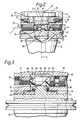
- Fig 2 shows a section through a first embodiment of coupling mechanism according to the present invention;
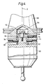
- Fig 3 shows a section through a second embodiment of coupling mechanism according to the present invention;
- Fig 4 shows a section through a third type of coupling mechanism according to the present invention; and
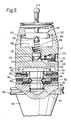
- Fig 5 shows a section through the preferred coupling mechanism of the present invention.
- Referring to Figs 1 and 2, a
touch probe 10 carries astylus 6 which terminates in aspherical measuring tip 8 for contacting a workpiece. Theprobe 10 is releasably coupled to ashank 12 which supports the probe in a head of a machine tool (not shown). Theprobe 10 has acylindrical housing 14 which terminates at the end of the probe adjacent the shank in a radially extendingannular lip 16 having an axially extendingflange 18 defining anaperture 20. The end of theshank 12 adjacent the probe has a radially extendingannular wall 22, which defines anaperture 23 and, (when the probe and shank are coupled together) receives theflange 18 with a clearance therebetween. - The
probe 10 andshank 12 are coupled by means of a clamping mechanism which comprises clamping pin 24, having ahead 26 and ashaft 28. The pin 24 is movably engaged with theprobe 10 by thehead 26 which lies inside the probe housing 14 and bears against thelip 16. Theshaft 28 of the bolt projects through theaperture 20 into acylindrical bore 30 in theshank 12. The cylindrical bore lies coaxially with the axis A of theshank 12. Theshaft 28 of the bolt has adiametric bore 32, and a substantiallycylindrical clamping element 34 is supported in thebore 32 for radial movement with respect to the axis A. Theclamping element 34 is provided with acircumferential channel 36, and a ball bearing 38 embedded in the surface of thebore 32 rests in the annular space defined by the surface of thebore 32 and thechannel 36, thereby to retain theclamping element 34 within thebore 32. Theclamping element 34 has, at one end, an outwardly projectingconical clamping surface 40, and at the other end an inwardly projecting conical clamping surface 42. Thesurface 40 engages an inwardly projectingconical surface 44 in the end of a fixedclamping bolt 46 which lies in a diametrically extending screw threadedbore 48 in the body of theshank 12.Moveable clamping bolt 50 also lies in the screw threadedbore 48, and has an outwardly projecting conical surface 52 which engages the inwardly projecting surface 42 of theelement 34. The axis B of theelement 34 lies closer to thewall 16 of theprobe 10, than the axis C of the moveable clamping bolt. - To clamp the
probe 10 andshank 12 together, themoveable clamping bolt 50 is driven down thebore 48 toward the axis A of theshank 12, until the outwardly projecting surface 52 of theclamping bolt 50 comes into contact with the inwardly projecting conical surface 42 of theclamping element 34. Initially, theelement 34 will be driven diametrically toward the fixedclamping bolt 46. However, once clampingbolt 46 has arrested the diametric movement ofelement 34, the action of outwardly projecting conical surface 52 on the inwardly projecting conical surface 42 will result in an axial force acting on theshaft 28 of the pin 24 in the direction ofshank 12. This will force thehead 26 against the inner surface oflip 16, and will clamp the probe and shank together. - Four adjusting
bolts 54 are supported by the shank and project radially through screw threadedbores 56 in theannular wall 22. Thebolts 54 bear against the outside of theflange 18, and adjustment of thesebolts 54 causes movement of the probe housing 14 relative to theshank 12 in a plane substantially orthogonal to the axis A. (Theflange 18 thus provides a shaft fixedly engaged with the probe against which the adjusting bolts may bear). When clamping theprobe 10 andshank 12 together, the preferred procedure is to tightenmoveable clamping bolt 50 until the clamping pin 24 retains theprobe 10 andshank 12 together with a pre-determined force, which is not sufficiently large to prevent relative lateral movement ofprobe 10 andshank 12, the relative position of the probe andshank 12 is then adjusted with adjustingbolts 54, until the centre of themeasuring tip 8 lies on the shank axis A. Theadjustable clamping screw 50 is then tightened further until theprobe 10 andshank 12 are retained together with the desired force. - A second embodiment of clamping assembly will now be described with reference to Fig 3. A
shank 60 has ashaft 62 formed integrally with the shank at one end. A substantiallycylindrical probe body 68 terminates at one end in anannular flange 70, defining anaxial bore 72. When the shank and probe body are engaged theshaft 62 projects into thebore 72. - As with the first embodiment, fixed and
moveable clamping bolts bores clamping element 80 is supported in a diametric bore in theshaft 62 for radial movement relative to theshaft 62, and one end of theclamping element 80 has an outwardly projectingwedge 82 having two inclined plane faces 83 which engage corresponding inwardly projectingplane surfaces 84 in the end of fixedclamping bolt 74. The other end ofclamping element 80 terminates in an inclinedplanar surface 88.Moveable clamping bolt 76 has an outwardly projectingconical surface 90, which, as thebolt 76 is driven inwardly down thebore 80, engages thesurface 88. As described previously, theclamping element 80 will initially move radially relative to the axis ofshaft 62 until its motion has been arrested by virtue of its engagement with fixedclamping bolt 74. At this point, the action ofmoveable clamping bolt 76 oninclined surface 88 will draw theshaft 62 into thebore 72, thereby clamping theshank 60 and the probe body together. - In order to damp any vibration between the
shank 60 and theprobe body 68, a spring mechanism 92 is provided. The mechanism 92 comprises a supportingring 94 which lies around the circumference ofshaft 62, and abelville washer 96 attached to the supportingring 94. The belville washer 96 bears against agroove 97 in the inner surface ofannular wall 70. - Four adjusting
bolts 98 are supported in radially extending screw threaded bores (not shown) in theprobe 68. Thescrews 98 bear against theshaft 62 and enable lateral adjustment of the shank relative to theprobe 68. The clamping procedure is as described in the first embodiment. - A third embodiment of the present invention will now be described, with reference to Fig 4.
- Referring now to Fig 4 a
probe 100 has, at its rear face ashaft 102 into which aretaining pin 104 is embedded. Both theshaft 102 and thepin 104 lie inside the retaining bore 106 in thetaper shank 108. The retainingpin 104 is sleeved by a clamping element in the form of acylindrical collar 110; thecollar 110 sleeves thepin 104 sufficiently loosely to allow relative movement of thepin 104 andcollar 110 perpendicular to the axis D ofshank 108. Thehead 112 of the retainingpin 104 bears against thecollar 110 via aBelleville washer 114. Thecollar 110 has aconical side face 116 and the largest diameter edge of thecollar 110 fits closely intobore 106. The entire assembly ofshaft 102,pin 104,collar 110 andwasher 114 comprises a projection which lies inside the recess (in this case, a bore 106) provided in theshank 108. - A
clamping bolt 118 projects into the retaining bore 106, in a direction radial to the axis D. The end face of theclamping bolt 118 is conical, and bears against theconcial face 116 of thecollar 110. Since the largest diameter of thecollar 110 is adjacent thehead 112 of thepin 104, inward radial movement of theclamping bolt 118 will cause thecollar 110 to move away from the body of theprobe 100, and therefore bear (via the Belleville washer 114), more strongly against thehead 112 of thepin 104. Thus, force applied to the collar by inward radial movement of thebolt 118, produces a resultant clamping force which clamps thetaper shank 108 and theprobe 100 together. - Radial adjustment of the relative alignment of the
probe 100 and tapershank 108 is accomplished by means of four adjustingbolts 120, each of which is supported in the body of thetaper shank 108 and extends radially into retainingbore 106 to bear against theshaft 102. - A coupling, and adjustment operation is thus performed as follows: the clamping
bolt 118 is first tightened to cause theprobe 100 to bear against theshank 108 with sufficient force to provide friction against relative radial movement of the two parts. The relative radial positions ofprobe 100 andshank 108 are then adjusted using the four adjustingbolts 120. Once this has been completed, theclamping bolt 118 is fully tightened, thus drawing theprobe 100 more firmly against theshank 108, without destroying the recently adjusted relative alignment of the two parts. - A fourth embodiment of the present invention will now be described with reference to Fig 5. A
probe 140 terminates at its rear end in anannular lip 142. Aclamping pin 144, having ahead 146 and ashaft 148 is moveably engaged with theprobe 140 by virtue of its contact between thehead 146 and thelip 142. Ashank 150 has aannular flange 152 which extends into ahole 154 defined by theannular lip 142. Theflange 152 sleeves theshaft 148 of thepin 144, which extends into abore 156 in theshank 150. Theshaft 148 has two mutually convergent frusto-conical faces 158, and a pair of clampingbolts 160, provided in diametrically extendingbores 162 each have aconical face 164, which bears against the frusto-conical surface remote from theprobe 140. Inward radial movement of one, or both the clampingbolts 160 will result in a force on theshaft 148 in an axial direction, causing thehead 146 of thepin 144 to bear against theannular lip 142, and urge theprobe 140 and theshank 150 together. Four radially extending, and equispaced adjustingbolts 166 extend in theannular lip 142, and bear aginst theflange 152 of theshank 150, which thus provides a fixed shaft against which the adjusting bolts may bear. The method of adjustment using this embodiment of the present invention is as described for the previous embodiments. - As stated earlier, the provision of three or more adjusting screws prevents relative movement of the tool and the shank (radially with respect to each other) when the tool and the shank are being clamped axially. Moreover, if the tool is to be used in conjunction with a tool change apparatus which grasps the shank to remove the tool from a magazine and insert it into a spindle, then the continual jarring of the tool during changing may cause misalignment between the tool and the shank. The provision of three or more radially extending adjusting screws helps to reduce this undesirable effect.
- It is not essential that either of the shafts (i.e. the fixed shafts provided by the probe and shank as appropriate, and the moveable shafts provided by the clamping pins) be cylindrical. For example, it may be desirable to provide square shafts, or triangular shafts (depending upon the number of adjusting, and clamping bolts employed).
- Typically, the touch probe illustrated in the embodiments of the present invention will be a touch trigger probe or an analogue touch probe. In either case, the stylus of the probe is supported on a stylus carrier, which is usually urged into a rest position with respect to the housing of the probe by a spring. The force required to displace the stylus from the said rest position is thus dependent directly upon the force with which the spring urges the stylus carrier into its rest position. It is ocassionally desirable to adjust the spring force. However adjustment of the spring force in existing touch probes is possible only by disengaging the probe from the shank. A third aspect of the present invention therefore provides means for adjusting the spring force of a touch probe while the probe is in situ (e.g. connected to a shank).
- According to a third aspect of the present invention there is provided a touch probe having:
a housing;
a stylus carrier supported relative to the housing in a rest position;
a spring, extending in a first direction and having one end bearing against the stylus carrier, and another end bearing against an abutment; and
means actuable from a second direction lateral to the first direction, for adjusting the position of the abutment in the first direction. - Preferably, the aubtment will comprise a clamping shuttle having an angled surface, so that a lateral adjusting force applied to the angled surface will result in movement of the clamping shuttle perpendicular to the applied force thus enabling adjustment of the position of the clamping shuttle in the first direction; such adjustment will cause a change in the degree of spring deformation and thus a change in the spring force.
- The adjusting force will preferably be applied by a screw, having an angled surface at its bearing end for bearing against the angled surface of the clamping shuttle.
- An example of such a touch probe will now be described with further reference to Fig 5.
- The stylus is supported in
probe housing 141 on astylus carrier 190, comprising abase 200, supported by threecylindrical rollers 202 which extend equidistant to each other and radially to the axis E. When the stylus carrier is in its rest position, each of therollers 202 seats in a cleft defined by an adjacent pair of steel balls 204 (of which only one is shown since the figure shows the stylus carrier in section). This kinematic arrangement is well-known, e.g. from US 4,153,998, and therefore need not be described in more detail. - The stylus carrier is urged into its kinematic rest position by a
spring mechanism 206 comprising aspring 208 which bears against the base 200 at one end via aconical member 210. The other end of thespring 208 bears against an abutment in the form of a cylindrical clampingshuttle 212 which is constrained to move in abore 214. The free end of the clampingshuttle 212 terminates in aconical face 216. Aradially extending bore 218 extends from the outer surface of the housing to thebore 214. The outer part of theradial bore 218 has a screw threaded part 220 in which aradial adjusting screw 222 sits. The adjustingscrew 222 has at its inner end in aconical face 224, which bears against theconical face 216 of the clampingshuttle 212. Thus, adjustment of theradial adjusting screw 222 causes movement of the clampingshuttle 212 along thebore 214, causing a change in the deformation of thespring 218 and thereby causing a change in the spring force which urges the stylus carrier into its kinematic rest position. The extent of the inward radial movement of theradial adjusting screw 222 is constrained by the countersunkseat 226.
Claims (9)
clamping means having: a) means (50;76;118;164) provided on one of the tool and shank for applying a force, radial with respect to the axis of the shank, on the other of the tool and shank;
b) means (42,26;88,62;116,102;158,144) provided on the other of the tool and shank, and operable by the radial force for producing a clamping force parallel to the axis to clamp the tool and shank together; and
adjusting means (18,54;62,98;102,120;152,166), distinct from the clamping means provided on one of the tool and the shank for aligning the two parts relative to each other transverse to said axis.
a first shaft (18;62;102;152) fixedly engaged with one of the tool and the shank, and projecting into the other of the tool and the shank; and
at least three adjusting bolts (54;98;120;166), supported by the other of the tool and the shank for bearing against the first shaft.
a clamping element (34;80;110) supported by the first shaft for movement relative to the first shaft radially with respect to the axis of the shank, the clamping element providing a clamping surface (42;88;116) inclined to the axis of the shank; and
at least one clamping bolt (50;76;118) supported by the other of the tool and the shank and extending substantially radially to the axis of the shank, for bearing against the clamping surface.
a second shaft (28;148), moveably engaged with one of the tool and shank, and extending into the other of the tool and the shank, the second shaft having a clamping surface (42;158) inclined to the axis of the shank; and
a clamping bolt (150;160) supported by the other of the tool and the shank and extending substantially radially to the axis of the shank, for bearing against the clamping surface.
Applications Claiming Priority (6)
| Application Number | Priority Date | Filing Date | Title |
|---|---|---|---|
| GB898907264A GB8907264D0 (en) | 1989-03-31 | 1989-03-31 | Coupling mechanism |
| GB8907264 | 1989-03-31 | ||
| GB898911198A GB8911198D0 (en) | 1989-05-16 | 1989-05-16 | Touch probe |
| GB8911198 | 1989-05-16 | ||
| GB8923747 | 1989-10-21 | ||
| GB898923747A GB8923747D0 (en) | 1989-10-21 | 1989-10-21 | Coupling mechanism |
Publications (3)
| Publication Number | Publication Date |
|---|---|
| EP0390342A2 true EP0390342A2 (en) | 1990-10-03 |
| EP0390342A3 EP0390342A3 (en) | 1991-01-09 |
| EP0390342B1 EP0390342B1 (en) | 1994-07-06 |
Family
ID=27264390
Family Applications (1)
| Application Number | Title | Priority Date | Filing Date |
|---|---|---|---|
| EP90302249A Expired - Lifetime EP0390342B1 (en) | 1989-03-31 | 1990-03-02 | Coupling mechanism |
Country Status (4)
| Country | Link |
|---|---|
| US (1) | US5040931A (en) |
| EP (1) | EP0390342B1 (en) |
| JP (1) | JP2945709B2 (en) |
| DE (1) | DE69010365T2 (en) |
Cited By (2)
| Publication number | Priority date | Publication date | Assignee | Title |
|---|---|---|---|---|
| US5208993A (en) * | 1991-03-28 | 1993-05-11 | Renishaw Metrology Limited | Touch probe |
| US6052628A (en) * | 1997-08-08 | 2000-04-18 | Hong; Jaiwei | Method and system for continuous motion digital probe routing |
Families Citing this family (13)
| Publication number | Priority date | Publication date | Assignee | Title |
|---|---|---|---|---|
| US5247751A (en) * | 1990-09-29 | 1993-09-28 | Nikon Corporation | Touch probe |
| DE4035841A1 (en) * | 1990-11-10 | 1992-05-14 | Wegu Messtechnik | DEVICE FOR INTERCHANGEABLE FASTENING OF A TAPP |
| SE9101689D0 (en) * | 1991-06-04 | 1991-06-04 | Mircona Ab | FAESTDON MAKES FRESH TOOLS AND SIMILAR |
| GB9225994D0 (en) * | 1992-12-12 | 1993-02-10 | Renishaw Metrology Ltd | Device for connecting a shank to a probe |
| SE500502C2 (en) * | 1993-06-11 | 1994-07-04 | Sandvik Ab | Adjusting device for cutting holder for rotary shell turning tool |
| AUPN268395A0 (en) * | 1995-04-27 | 1995-05-25 | Ziegler, Karl | Improvements in machine tools |
| US6270293B2 (en) * | 1998-12-22 | 2001-08-07 | Kennametal Pc Inc. | Toolholder assembly |
| SE0103523D0 (en) * | 2001-10-19 | 2001-10-19 | Abb Ab | Industrial robot |
| DE10258448A1 (en) * | 2002-12-13 | 2004-06-24 | Franz Haimer Maschinenbau Kg | Centering device, especially for contact measurement device, has centering holder in form of parallelogram guide with one or more linkage regions distributed about shaft axis and equipment axis |
| US6966728B1 (en) * | 2004-06-08 | 2005-11-22 | Kennametal Inc. | Toolholder assembly |
| WO2007031285A1 (en) * | 2005-09-13 | 2007-03-22 | Komet Group Holding Gmbh | Device for detachably coupling two parts |
| CN102385035A (en) * | 2010-08-31 | 2012-03-21 | 深圳富泰宏精密工业有限公司 | Touch key test pen |
| US10663274B2 (en) * | 2017-01-27 | 2020-05-26 | Faro Technologies, Inc | Articulated arm coordinate measuring machine |
Citations (4)
| Publication number | Priority date | Publication date | Assignee | Title |
|---|---|---|---|---|
| DE8633959U1 (en) * | 1986-12-19 | 1988-04-14 | Komet Stahlhalter- Und Werkzeugfabrik Robert Breuning Gmbh, 7122 Besigheim, De | |
| EP0275441A1 (en) * | 1986-12-23 | 1988-07-27 | Hertel Aktiengesellschaft Werkzeuge + Hartstoffe | Clamping device |
| EP0281760A2 (en) * | 1987-03-11 | 1988-09-14 | Firma Gottlieb Gühring | Coupling system for a cutting tool having a shaft |
| EP0164582B1 (en) * | 1984-05-12 | 1989-01-11 | Manfred König | Mounting device for centred mounting of rotating parts |
Family Cites Families (18)
| Publication number | Priority date | Publication date | Assignee | Title |
|---|---|---|---|---|
| US2435396A (en) * | 1944-12-04 | 1948-02-03 | Koch Alfred Fred | Centering ring for adjustable toolholders |
| US3178192A (en) * | 1963-02-07 | 1965-04-13 | Sp Mfg Corp | Adjustable universal chuck |
| US3767218A (en) * | 1973-02-21 | 1973-10-23 | Carrier Corp | Tool chuck |
| DE8106316U1 (en) * | 1981-01-29 | 1982-08-26 | Komet Stahlhalter- Und Werkzeugfabrik Robert Breuning Gmbh, 7122 Besigheim | DRILLING TOOL |
| US4779319A (en) * | 1981-04-30 | 1988-10-25 | Gte Valeron Corporation | Method and apparatus for performing workpiece inspection with a probe |
| GB2101018B (en) * | 1981-06-05 | 1986-06-11 | Bassett R R | Improvements in or relating to drive assemblies |
| US4510693A (en) * | 1982-06-14 | 1985-04-16 | Gte Valeron Corporation | Probe with stylus adjustment |
| DE3324312C2 (en) * | 1983-04-20 | 1985-11-28 | Komet Stahlhalter- Und Werkzeugfabrik Robert Breuning Gmbh, 7122 Besigheim | Machine tool with tool changing device |
| DE3401200A1 (en) * | 1984-01-14 | 1985-07-25 | Komet Stahlhalter- Und Werkzeugfabrik Robert Breuning Gmbh, 7122 Besigheim | Drilling and turning-out tool |
| DE8422976U1 (en) * | 1984-08-02 | 1985-11-28 | Komet Stahlhalter- Und Werkzeugfabrik Robert Breuning Gmbh, 7122 Besigheim | Tool holder with radial adjustment device for a tool, in particular a rotating tool |
| ATE55716T1 (en) * | 1986-03-03 | 1990-09-15 | Dihart Ag | TOOL HOLDER. |
| DE8631442U1 (en) * | 1986-11-25 | 1988-03-24 | Komet Stahlhalter- Und Werkzeugfabrik Robert Breuning Gmbh, 7122 Besigheim, De | |
| JPS6393505U (en) * | 1986-12-10 | 1988-06-16 | ||
| DE8708935U1 (en) * | 1987-05-27 | 1987-10-22 | Ledermann Gmbh + Co, 7240 Horb, De | |
| DE8715525U1 (en) * | 1987-11-24 | 1989-03-23 | Komet Stahlhalter- Und Werkzeugfabrik Robert Breuning Gmbh, 7122 Besigheim, De | |
| SE467449B (en) * | 1988-05-06 | 1992-07-20 | Seco Tools Ab | DEVICE FOR CONNECTING A HANDLE AND A SHEET AND A SCREW UNIT THEREOF, WHICH TENSION ELEMENTS IN THE SHEET COULD COOPERATE WITH A RADIALLY RELEASABLE LOCKER |
| DE3823042A1 (en) * | 1988-07-07 | 1990-01-11 | Zeiss Carl Fa | COORDINATE MEASURING DEVICE |
| US4991306A (en) * | 1990-06-25 | 1991-02-12 | Raiha A P | Tactile center locator |
-
1990
- 1990-03-02 DE DE69010365T patent/DE69010365T2/en not_active Expired - Lifetime
- 1990-03-02 EP EP90302249A patent/EP0390342B1/en not_active Expired - Lifetime
- 1990-03-19 US US07/495,751 patent/US5040931A/en not_active Expired - Lifetime
- 1990-03-31 JP JP2087312A patent/JP2945709B2/en not_active Expired - Fee Related
Patent Citations (4)
| Publication number | Priority date | Publication date | Assignee | Title |
|---|---|---|---|---|
| EP0164582B1 (en) * | 1984-05-12 | 1989-01-11 | Manfred König | Mounting device for centred mounting of rotating parts |
| DE8633959U1 (en) * | 1986-12-19 | 1988-04-14 | Komet Stahlhalter- Und Werkzeugfabrik Robert Breuning Gmbh, 7122 Besigheim, De | |
| EP0275441A1 (en) * | 1986-12-23 | 1988-07-27 | Hertel Aktiengesellschaft Werkzeuge + Hartstoffe | Clamping device |
| EP0281760A2 (en) * | 1987-03-11 | 1988-09-14 | Firma Gottlieb Gühring | Coupling system for a cutting tool having a shaft |
Cited By (2)
| Publication number | Priority date | Publication date | Assignee | Title |
|---|---|---|---|---|
| US5208993A (en) * | 1991-03-28 | 1993-05-11 | Renishaw Metrology Limited | Touch probe |
| US6052628A (en) * | 1997-08-08 | 2000-04-18 | Hong; Jaiwei | Method and system for continuous motion digital probe routing |
Also Published As
| Publication number | Publication date |
|---|---|
| DE69010365T2 (en) | 1994-11-03 |
| EP0390342A3 (en) | 1991-01-09 |
| JPH02284808A (en) | 1990-11-22 |
| JP2945709B2 (en) | 1999-09-06 |
| EP0390342B1 (en) | 1994-07-06 |
| DE69010365D1 (en) | 1994-08-11 |
| US5040931A (en) | 1991-08-20 |
Similar Documents
| Publication | Publication Date | Title |
|---|---|---|
| US5040931A (en) | Coupling mechanism | |
| JP5139789B2 (en) | Workpiece carrier for accurately positioning a work piece on a chuck and a clamping device having a chuck and a work piece carrier | |
| JP2002536631A (en) | Tightening device for tightening rotating mechanical elements and balance tester with the tightening device | |
| JPH0457441B2 (en) | ||
| US5314198A (en) | Collet chuck apparatus | |
| US4776734A (en) | Tool holder | |
| JPH1110418A (en) | Retaining tool | |
| US5212872A (en) | Touch probe | |
| JP4972362B2 (en) | Diaphragm chuck | |
| KR20200118372A (en) | Clamping device with planar contact | |
| JP2005538854A (en) | Method and apparatus for clamping a rotational symmetry body and structure of the rotational symmetry body to be clamped | |
| US3347115A (en) | Axially adjustable tool holder construction | |
| JP4256029B2 (en) | Machine tool drive | |
| JP2018069360A (en) | Axis connection adjusting mechanism | |
| US3746353A (en) | Collet chuck adapter | |
| US11945071B2 (en) | Polishing brush and polishing method | |
| US5354157A (en) | Device for connecting a shank to a probe | |
| JPH04507381A (en) | Tools for use in machine tools | |
| US9586269B2 (en) | Collet adapter | |
| RU219109U1 (en) | Device for axial fixation of workpieces | |
| JPH05111811A (en) | Mountable mandrel with spindle device for tool | |
| JPH0796437A (en) | Tool holder | |
| JPH06297202A (en) | Spindle head for machine tool and method for use thereof | |
| JPH04223833A (en) | Tool holder clamping device | |
| KR20210111972A (en) | Spindle clamping device of machine tool |
Legal Events
| Date | Code | Title | Description |
|---|---|---|---|
| PUAI | Public reference made under article 153(3) epc to a published international application that has entered the european phase |
Free format text: ORIGINAL CODE: 0009012 |
|
| 17P | Request for examination filed |
Effective date: 19900313 |
|
| AK | Designated contracting states |
Kind code of ref document: A2 Designated state(s): CH DE FR GB IT LI SE |
|
| PUAL | Search report despatched |
Free format text: ORIGINAL CODE: 0009013 |
|
| AK | Designated contracting states |
Kind code of ref document: A3 Designated state(s): CH DE FR GB IT LI SE |
|
| RAP3 | Party data changed (applicant data changed or rights of an application transferred) |
Owner name: RENISHAW PLC |
|
| 17Q | First examination report despatched |
Effective date: 19930215 |
|
| GRAA | (expected) grant |
Free format text: ORIGINAL CODE: 0009210 |
|
| ITF | It: translation for a ep patent filed |
Owner name: BARZANO' E ZANARDO MILANO S.P.A. |
|
| AK | Designated contracting states |
Kind code of ref document: B1 Designated state(s): CH DE FR GB IT LI SE |
|
| PG25 | Lapsed in a contracting state [announced via postgrant information from national office to epo] |
Ref country code: FR Effective date: 19940706 |
|
| REF | Corresponds to: |
Ref document number: 69010365 Country of ref document: DE Date of ref document: 19940811 |
|
| PG25 | Lapsed in a contracting state [announced via postgrant information from national office to epo] |
Ref country code: SE Effective date: 19941006 |
|
| EN | Fr: translation not filed | ||
| PG25 | Lapsed in a contracting state [announced via postgrant information from national office to epo] |
Ref country code: LI Effective date: 19950331 Ref country code: CH Effective date: 19950331 |
|
| PLBE | No opposition filed within time limit |
Free format text: ORIGINAL CODE: 0009261 |
|
| STAA | Information on the status of an ep patent application or granted ep patent |
Free format text: STATUS: NO OPPOSITION FILED WITHIN TIME LIMIT |
|
| 26N | No opposition filed | ||
| REG | Reference to a national code |
Ref country code: CH Ref legal event code: PL |
|
| REG | Reference to a national code |
Ref country code: GB Ref legal event code: IF02 |
|
| PGFP | Annual fee paid to national office [announced via postgrant information from national office to epo] |
Ref country code: GB Payment date: 20090325 Year of fee payment: 20 |
|
| PGFP | Annual fee paid to national office [announced via postgrant information from national office to epo] |
Ref country code: DE Payment date: 20090320 Year of fee payment: 20 Ref country code: IT Payment date: 20090325 Year of fee payment: 20 |
|
| REG | Reference to a national code |
Ref country code: GB Ref legal event code: PE20 Expiry date: 20100301 |
|
| PG25 | Lapsed in a contracting state [announced via postgrant information from national office to epo] |
Ref country code: GB Free format text: LAPSE BECAUSE OF EXPIRATION OF PROTECTION Effective date: 20100301 |
|
| PG25 | Lapsed in a contracting state [announced via postgrant information from national office to epo] |
Ref country code: DE Free format text: LAPSE BECAUSE OF EXPIRATION OF PROTECTION Effective date: 20100302 |