EP0384490A2 - Echo canceller having FIR and IIR filters for cancelling long tail echoes - Google Patents
Echo canceller having FIR and IIR filters for cancelling long tail echoes Download PDFInfo
- Publication number
- EP0384490A2 EP0384490A2 EP90103601A EP90103601A EP0384490A2 EP 0384490 A2 EP0384490 A2 EP 0384490A2 EP 90103601 A EP90103601 A EP 90103601A EP 90103601 A EP90103601 A EP 90103601A EP 0384490 A2 EP0384490 A2 EP 0384490A2
- Authority
- EP
- European Patent Office
- Prior art keywords
- symbol
- tap
- output
- multiplying
- multiplier
- Prior art date
- Legal status (The legal status is an assumption and is not a legal conclusion. Google has not performed a legal analysis and makes no representation as to the accuracy of the status listed.)
- Granted
Links
- 238000002592 echocardiography Methods 0.000 title description 9
- 230000003111 delayed effect Effects 0.000 claims abstract description 24
- 238000006243 chemical reaction Methods 0.000 claims description 11
- 238000005094 computer simulation Methods 0.000 description 5
- 230000005540 biological transmission Effects 0.000 description 4
- 238000010586 diagram Methods 0.000 description 3
- 238000004260 weight control Methods 0.000 description 3
- 230000004048 modification Effects 0.000 description 2
- 238000012986 modification Methods 0.000 description 2
- 230000008878 coupling Effects 0.000 description 1
- 238000010168 coupling process Methods 0.000 description 1
- 238000005859 coupling reaction Methods 0.000 description 1
- JHIVVAPYMSGYDF-UHFFFAOYSA-N cyclohexanone Chemical compound O=C1CCCCC1 JHIVVAPYMSGYDF-UHFFFAOYSA-N 0.000 description 1
- 238000004445 quantitative analysis Methods 0.000 description 1
Images


Classifications
-
- H—ELECTRICITY
- H04—ELECTRIC COMMUNICATION TECHNIQUE
- H04B—TRANSMISSION
- H04B3/00—Line transmission systems
- H04B3/02—Details
- H04B3/20—Reducing echo effects or singing; Opening or closing transmitting path; Conditioning for transmission in one direction or the other
- H04B3/23—Reducing echo effects or singing; Opening or closing transmitting path; Conditioning for transmission in one direction or the other using a replica of transmitted signal in the time domain, e.g. echo cancellers
- H04B3/237—Reducing echo effects or singing; Opening or closing transmitting path; Conditioning for transmission in one direction or the other using a replica of transmitted signal in the time domain, e.g. echo cancellers using two adaptive filters, e.g. for near end and for end echo cancelling
-
- H—ELECTRICITY
- H04—ELECTRIC COMMUNICATION TECHNIQUE
- H04B—TRANSMISSION
- H04B3/00—Line transmission systems
- H04B3/02—Details
- H04B3/20—Reducing echo effects or singing; Opening or closing transmitting path; Conditioning for transmission in one direction or the other
- H04B3/23—Reducing echo effects or singing; Opening or closing transmitting path; Conditioning for transmission in one direction or the other using a replica of transmitted signal in the time domain, e.g. echo cancellers
- H04B3/238—Reducing echo effects or singing; Opening or closing transmitting path; Conditioning for transmission in one direction or the other using a replica of transmitted signal in the time domain, e.g. echo cancellers using initial training sequence
Definitions
- the present invention relates generally to echo cancellers for a digital communications system, and more particularly to an echo canceller capable of cancelling echoes having a long tail portion.
- the echo canceller of this type has a nonrecursive, or finite impulse response (FIR) filter. Because of the finite number of tap weights, the whole shape of an echo cannot completely be cancelled if it has a long tail portion. A great number of tap weights must be required for complete cancellation of echoes. It is generally known that such a long-tail echo occurs due to the high-pass characteristic of a hybrid, or two-wire four-wire conversion circuit. A typical waveform of such long-tail echoes is one that adopts a negative exponential curve.
- FIR finite impulse response
- the remaining tail portion lies outside the range of tap weight control of the FIR filter and remains uncancelled, causing residual echoes to accumulate if t > NT, where t is the length of an echo, T is a symbol interval and N is the number of tap weights.
- European Patent Application 0 281 101 discloses an echo canceller which is capable of cancelling long-tail echoes. However, it needs two recursive filters (Infinite Impulse Response filter) to form a tail canceller in addition to a nonrecursive filter.
- recursive filters Infinite Impulse Response filter
- an echo canceller comprises a finite impulse response filter (FIR) and a tail canceller.
- the finite impulse response filter comprises a tapped-delay line connected to an incoming port of a hybrid, or two-wire four-wire conversion circuit, a plurality of first tap-weight multipliers connected respectively to the successive taps of the delay line for respectively multiplying successively delayed digital symbols with first tap-weight coefficients and an adder for summing the outputs of the first tap-weight multipliers.
- the tail canceller comprises an infinite impulse response filter having a second multiplier for recursively multiplying an output digital symbol from the tapped-delay line with a second, attenuation coefficient R.
- a third multiplier is included in the tail canceller for multiplying an output digital symbol of the IIR filter with a third, tap-weight coefficient C; and applying the multiplied output symbol to one input of the adder to cause it to produce a replica of an echo symbol which is subtracted from digital symbols supplied from an outgoing port of the conversion circuit, producing a residual echo symbol.
- a symbol appearing at the output end of the tapped-delay line is further delayed on the one hand, and multiplied with the second, attenuation coefficient R on the other.
- the difference between the delayed and multiplied symbols is detected and further multiplied with a coefficient K which varies as a function of the third, tap-weight coefficient C ; to generate a multiplied difference.
- the first tap-weight coefficients of the FIR filter are derived from correlations between the residual echo symbol and the successively delayed digital symbols on the tapped-delay line.
- the second, attenuation coefficient R is derived from a correlation between the residual echo symbol and the multiplied difference.
- the third, tap-weight coefficient C is derived from a correlation between the residual echo symbol and a digital symbol from the end of the tapped-delay line.
- the tail canceller comprises a second multiplier which multiplies an output digital symbol from the end of the tapped-delay line of the FIR filter with a second, tap-weight coefficient C; and an infinite impulse response filter having a multiplier for recursively multiplying the output of the second multiplier with a third, attenuation coefficient R and applying the multiplied output to one input of the adder to cause it to produce a replica of an echo symbol which is subtracted from digital symbols supplied from the outgoing port of the conversion circuit, producing a residual echo symbol.
- a digital symbol a n .
- N from the tapped-delay line of the FIR filter is further delayed and multiplied with the coefficient K to produce a symbol K x a n-N-1 .
- the second, tap-weight coefficient C is derived from a correlation between the residual echo symbol and a digital symbol from the tapped-delay line
- the third, attenuation coefficient R is derived from a correlation between the residual echo symbol and the symbol K x a n.N-1 .
- the coefficient K is a signum function of coefficient C;, i.e., sgn(C ; ) which is + 1 when C; is greater than zero and -1 when C; is smaller than zero, or alternatively, the reciprocal of C ; .
- Hybrid 1 has a two-wire port 2 connected to a non-repeatered transmission line (usually a subscriber line), an incoming two-wire port 3 for receiving an incoming digital symbol a n from the receive end of a repeatered transmission line and an outgoing two-wire port 4 at which an outgoing, echo-containing digital symbol Yn appears.
- a non-repeatered transmission line usually a subscriber line
- an incoming two-wire port 3 for receiving an incoming digital symbol a n from the receive end of a repeatered transmission line
- an outgoing two-wire port 4 at which an outgoing, echo-containing digital symbol Yn appears.
- the echo canceller of this invention generally comprises a nonrecursive, or finite impulse response (FIR) filter 6 for cancelling a greater part of an echo and a tail canceller 7 which are cascaded from the incoming port 3 to produce a signal at the input of a subtractor 23 that cancels the whole waveform of an echo generated at the outgoing port 4 as a result of trans-hybrid coupling between the ports 3 and 4.
- the output of subtractor 23 represents a residual echo symbol e n , which appears at an output terminal 5 to which the transmit end of a non-repeatered transmission line is connected.
- FIR filter 6 includes a series circuit of delay elements, or shift registers 1-1 through 1-N for successively delaying an incoming digital symbol a n for interval T which is the reciprocal of the symbol rate of the digital signal, so that at given instant of time, a series of successively delayed digital symbols a n-1 , an- 2 . a n-3 across an- N appear respectively at the outputs of shift registers 8-1, 8-2, 8-3, ... and 8-N.
- the input terminals of shift registers 8 are connected respectively to tap-weight multipliers 9-1 through 9-N respectively having tap-weight coefficients C, through C N .
- tap-weight coefficients are supplied respectively from correlators 10-1 through 10-N which are connected to the inputs of shift registers 8-1-8-N for detecting correlations between successively delayed digital symbols and residual echo symbol e n from subtractor 23
- the output digital symbols from tap-weight multipliers 9-1-9-N are summed by an adder 11.
- shift register 9-N is supplied to the input of tail canceller 7 which comprises a recursive, or infinite impulse response filter 25 formed by an adder 12, a shift register 13 connected to the output of adder 12 to introduce a delay time T and a multiplier 14 which multiplies the output of shift register 13 with a loop attenuator coefficient R supplied from a correlator 22.
- Digital symbol a n . N from shift register 8-N is summed with the output of multiplier 14 to produce an output symbol U n which is supplied to a tap-weight multiplier 15 having a tap-weight coefficient C i supplied from a correlator 16.
- Correlator 16 detects correlation between residual echo symbol e n from subtractor 23 and digital symbol U n to adaptively control the tap weight of multiplier 15.
- the digital symbol C i x U n from multiplier 15 is supplied to adder 11 as an output digital symbol of tail canceller 7 and summed with the outputs of multipliers 9-1-9-N of FIR filter 6.
- the input signal of correlator 16 can be taken from the output of shift register 8-N as illustrated in Fig. 2, instead of from the output of adder 12.
- the digital symbol a n-N from shift register 8-N is also supplied to a shift register 17 to produce a delayed symbol a n-N-1 as well as to a multiplier 18 to multiply a n-N by the loop attenuation coefficient R from correlator 22.
- a subtractor 19 is connected to the outputs of shift register 17 and multiplier 18 to generate a digital symbol representing the difference between the delayed symbol a n-N-1 and the multiplied symbol R x a n . N . i.e., a n-N-1 - Rx x a n-N .
- This output of subtractor 19 is multiplied by a multiplier 20 with a coefficient K which varies as a function of coefficient C;.
- the coefficient K is a polarity signal "+ 1 " or "-1” depending on.the tap-weight coefficient C i from correlator 16.
- a signum function generator 21 is connected to the output of correlator 16 to derive the signal sgn(C i ), i.e., a polarity bit "1” if the output of correlator C; is greater than 0 or a polarity bit "-1” if C i is smaller than 0. Therefore, the output of multiplier 20 is represented by (a n-N-1 - R x a n . N ) or - (a n-N-1 - R x a n-N ), which is supplied to a first input of correlator 22 whose second input is supplied with the residual echo symbol e n from subtractor 23.
- the tap-weight coefficient C; of multiplier 15 is adaptively controlled by the correlation between e n and U n and loop attenuation coefficient R of multipliers 14 and 18 is adaptively controlled by the correlation between e n and (a n-N-1 - R x a n-N ) sgn(C i ).
- the multiplier 20 can be controlled with the reciprocal of the tap-weight coefficient C i , i.e., 1/C i , derived by a circuit 25 as illustrated in Fig. 3, to apply a signal (a n-N-1 - R x a n-N )/C i to correlator 22.
- correlator 16 comprises a multiplier 50 which multiplies residual echo symbol e n from subtractor 23 with a symbol a n . N from shift register 8-N.
- the output of multiplier 50 is further multiplied by a multiplier 51 with an adjustment constant ⁇ i and supplied to a first input of an adder 52.
- correlator 22 comprises a multiplier 60 which multiplies residual echo symbol e n with the output of multiplier 20 which is represented by (a n . N - R (n) x a n . N ) sgn(C i (n) ).
- the output of multiplier 60 is further multiplied by a multiplier 61 with an adjustment constant ⁇ r and supplied to a first input of an adder 62.
- Equation (4) represents the error associated with the FIR filter 6.
- the input digital symbol is represented by a random sequence of binary + 1 and -1 and the following initial values are used: With the computer simulation, coefficients C i and R were converged respectively to -0.0118 and 0.96907. Fig.
- the echo canceller according to the first embodiment of this invention effectively cancels long-tail echoes using only one recursive filter 24.
- tail canceller 7A comprises a tap-weight multiplier 30 connected to the output of shift register 8-N, and an IIR filter 40 formed by an adder 31 having one input connected to the output of adder 30, a shift register 32 for delaying the output signal from adder 31 for a unit delay time T, and a second tap-weight multiplier 33 connected between the output of shift register 32 and the second input of adder 31.
- the tap weight of first multiplier 30 is controlled by a signal representing the tap-weight coefficient C i from a correlator 34 which detects correlation between residual echo symbol e n and the digital symbol a n . N appearing at the input of multiplier 30.
- the tap weight of second multiplier 33 is controlled by a signal representing the loop attenuation coefficient R supplied from a correlator 35 which detects correlation between the residual echo symbol and the output of a multiplier 37.
- the output of adder 31 is further connected to adder 11 where the output digital symbol of tail canceller 7A is summed with the outputs of tap-weight multipliers 9-1-9-N.
- Tail canceller 7A further includes a shift register 36 for delaying the digital symbol a n . N from shift register 8-N for a unit delay time T.
- a signum function generator 38 is connected to the output of correlator 34 to supply a polarity bit sgn(C i ) to multiplier 37.
- the output shift register 36 is multiplied with this polarity bit sgn(C i ) to supply a signal (a n-N-1 ) sgn(C;) to correlator 35 to detect correlation between (a n-N-1 ) sgn(C;) and e n .
- Correlators 34 and 35 are similar to correlators 16 and 22 of the previous embodiment, respectively.
- Residual error is therefore given by: where, ⁇ (n) m R (n) R (n-1) ....R (n-m+1)
- the expectation values of C i (n) and R (n) are assumed as follows: where, R h h N+1 /h N , and 0 ⁇ 1 - ⁇ i a 2 , 1 - ⁇ i
- the tail canceller 7A of Fig. 6 is also capable of completely cancelling the tail portion of an echo.
Abstract
Description
- The present invention relates generally to echo cancellers for a digital communications system, and more particularly to an echo canceller capable of cancelling echoes having a long tail portion.
- Two-wire subscriber lines employing an echo canceller are known in the art. The echo canceller of this type has a nonrecursive, or finite impulse response (FIR) filter. Because of the finite number of tap weights, the whole shape of an echo cannot completely be cancelled if it has a long tail portion. A great number of tap weights must be required for complete cancellation of echoes. It is generally known that such a long-tail echo occurs due to the high-pass characteristic of a hybrid, or two-wire four-wire conversion circuit. A typical waveform of such long-tail echoes is one that adopts a negative exponential curve. While the main portion of such a waveform can be cancelled, the remaining tail portion lies outside the range of tap weight control of the FIR filter and remains uncancelled, causing residual echoes to accumulate if t > NT, where t is the length of an echo, T is a symbol interval and N is the number of tap weights.
-
European Patent Application 0 281 101 (published on January 31, 1990) discloses an echo canceller which is capable of cancelling long-tail echoes. However, it needs two recursive filters (Infinite Impulse Response filter) to form a tail canceller in addition to a nonrecursive filter. - It is therefore an object of the present invention to provide an echo canceller capable of cancelling long tail echoes with a simplified tail canceller.
- According to a first aspect of the invention, an echo canceller comprises a finite impulse response filter (FIR) and a tail canceller. The finite impulse response filter comprises a tapped-delay line connected to an incoming port of a hybrid, or two-wire four-wire conversion circuit, a plurality of first tap-weight multipliers connected respectively to the successive taps of the delay line for respectively multiplying successively delayed digital symbols with first tap-weight coefficients and an adder for summing the outputs of the first tap-weight multipliers. The tail canceller comprises an infinite impulse response filter having a second multiplier for recursively multiplying an output digital symbol from the tapped-delay line with a second, attenuation coefficient R. A third multiplier is included in the tail canceller for multiplying an output digital symbol of the IIR filter with a third, tap-weight coefficient C; and applying the multiplied output symbol to one input of the adder to cause it to produce a replica of an echo symbol which is subtracted from digital symbols supplied from an outgoing port of the conversion circuit, producing a residual echo symbol. A symbol appearing at the output end of the tapped-delay line is further delayed on the one hand, and multiplied with the second, attenuation coefficient R on the other. The difference between the delayed and multiplied symbols is detected and further multiplied with a coefficient K which varies as a function of the third, tap-weight coefficient C; to generate a multiplied difference. The first tap-weight coefficients of the FIR filter are derived from correlations between the residual echo symbol and the successively delayed digital symbols on the tapped-delay line. The second, attenuation coefficient R is derived from a correlation between the residual echo symbol and the multiplied difference. The third, tap-weight coefficient C; is derived from a correlation between the residual echo symbol and a digital symbol from the end of the tapped-delay line.
- According to a second aspect of the present invention, the tail canceller comprises a second multiplier which multiplies an output digital symbol from the end of the tapped-delay line of the FIR filter with a second, tap-weight coefficient C;, and an infinite impulse response filter having a multiplier for recursively multiplying the output of the second multiplier with a third, attenuation coefficient R and applying the multiplied output to one input of the adder to cause it to produce a replica of an echo symbol which is subtracted from digital symbols supplied from the outgoing port of the conversion circuit, producing a residual echo symbol. A digital symbol an.N from the tapped-delay line of the FIR filter is further delayed and multiplied with the coefficient K to produce a symbol K x an-N-1. The second, tap-weight coefficient C; is derived from a correlation between the residual echo symbol and a digital symbol from the tapped-delay line, and the third, attenuation coefficient R is derived from a correlation between the residual echo symbol and the symbol K x an.N-1.
- The coefficient K is a signum function of coefficient C;, i.e., sgn(C;) which is + 1 when C; is greater than zero and -1 when C; is smaller than zero, or alternatively, the reciprocal of C;.
- The present invention will be described in further detail with reference to the accompanying drawings, in which:
- Fig. 1 is a block diagram of an echo canceller according to a first embodiment of the present invention;
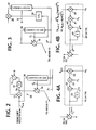
- Figs. 2 and 3 are block diagrams of alternative forms of the first embodiment;
- Figs. 4A and 4B show details of the correlators of Fig. 1;
- Fig. 5 is a graphic representation of a computer simulation of the first embodiment;
- Fig. 6 is a block diagram of an echo canceller according to a second embodiment of the invention; and
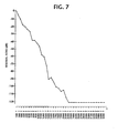
- Fig. 7 is a graphic representation of a computer simulation of the second embodiment.
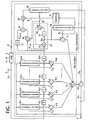
- Referring now to Fig. 1, there is shown an echo canceller according to a first embodiment of the present invention. The echo canceller is shown connected in a four-wire section of a two-wire four-wire conversion circuit, or
hybrid 1 of a digital transmission system.Hybrid 1 has a two-wire port 2 connected to a non-repeatered transmission line (usually a subscriber line), an incoming two-wire port 3 for receiving an incoming digital symbol an from the receive end of a repeatered transmission line and an outgoing two-wire port 4 at which an outgoing, echo-containing digital symbol Yn appears. - The echo canceller of this invention generally comprises a nonrecursive, or finite impulse response (FIR)
filter 6 for cancelling a greater part of an echo and atail canceller 7 which are cascaded from the incoming port 3 to produce a signal at the input of asubtractor 23 that cancels the whole waveform of an echo generated at theoutgoing port 4 as a result of trans-hybrid coupling between theports 3 and 4. The output ofsubtractor 23 represents a residual echo symbol en, which appears at an output terminal 5 to which the transmit end of a non-repeatered transmission line is connected. -
FIR filter 6 includes a series circuit of delay elements, or shift registers 1-1 through 1-N for successively delaying an incoming digital symbol an for interval T which is the reciprocal of the symbol rate of the digital signal, so that at given instant of time, a series of successively delayed digital symbols an-1, an-2. an-3..... an-N appear respectively at the outputs of shift registers 8-1, 8-2, 8-3, ... and 8-N. The input terminals ofshift registers 8 are connected respectively to tap-weight multipliers 9-1 through 9-N respectively having tap-weight coefficients C, through CN. These tap-weight coefficients are supplied respectively from correlators 10-1 through 10-N which are connected to the inputs of shift registers 8-1-8-N for detecting correlations between successively delayed digital symbols and residual echo symbol en fromsubtractor 23 The output digital symbols from tap-weight multipliers 9-1-9-N are summed by anadder 11. - The output of shift register 9-N is supplied to the input of
tail canceller 7 which comprises a recursive, or infiniteimpulse response filter 25 formed by anadder 12, ashift register 13 connected to the output ofadder 12 to introduce a delay time T and amultiplier 14 which multiplies the output ofshift register 13 with a loop attenuator coefficient R supplied from acorrelator 22. Digital symbol an.N from shift register 8-N is summed with the output ofmultiplier 14 to produce an output symbol Un which is supplied to a tap-weight multiplier 15 having a tap-weight coefficient Ci supplied from acorrelator 16.Correlator 16 detects correlation between residual echo symbol en fromsubtractor 23 and digital symbol Un to adaptively control the tap weight ofmultiplier 15. The digital symbol Ci x Un frommultiplier 15 is supplied to adder 11 as an output digital symbol oftail canceller 7 and summed with the outputs of multipliers 9-1-9-N ofFIR filter 6. Alternatively, the input signal ofcorrelator 16 can be taken from the output of shift register 8-N as illustrated in Fig. 2, instead of from the output ofadder 12. - The digital symbol an-N from shift register 8-N is also supplied to a
shift register 17 to produce a delayed symbol an-N-1 as well as to amultiplier 18 to multiply an-N by the loop attenuation coefficient R fromcorrelator 22. Asubtractor 19 is connected to the outputs ofshift register 17 and multiplier 18 to generate a digital symbol representing the difference between the delayed symbol an-N-1 and the multiplied symbol R x an.N. i.e., an-N-1- Rx x an-N. This output ofsubtractor 19 is multiplied by amultiplier 20 with a coefficient K which varies as a function of coefficient C;. Specifically, the coefficient K is a polarity signal "+ 1 " or "-1" depending on.the tap-weight coefficient Ci fromcorrelator 16. To this end, asignum function generator 21 is connected to the output ofcorrelator 16 to derive the signal sgn(Ci), i.e., a polarity bit "1" if the output of correlator C; is greater than 0 or a polarity bit "-1" if Ci is smaller than 0. Therefore, the output ofmultiplier 20 is represented by (an-N-1- R x an.N) or - (an-N-1- R x an-N), which is supplied to a first input ofcorrelator 22 whose second input is supplied with the residual echo symbol en fromsubtractor 23. - Therefore, the tap-weight coefficient C; of
multiplier 15 is adaptively controlled by the correlation between en and Un and loop attenuation coefficient R ofmultipliers multiplier 20 can be controlled with the reciprocal of the tap-weight coefficient Ci, i.e., 1/Ci, derived by acircuit 25 as illustrated in Fig. 3, to apply a signal (an-N-1- R x an-N)/Ci tocorrelator 22. - Details of
correlators correlator 16 comprises amultiplier 50 which multiplies residual echo symbol en fromsubtractor 23 with a symbol an.N from shift register 8-N. The output ofmultiplier 50 is further multiplied by amultiplier 51 with an adjustment constant αi and supplied to a first input of anadder 52. Ashift register 53 is connected to the output ofadder 52 to delay its output symbol for a unit-time delay to produce a coefficient C(n) and applies it to the second input ofadder 52, producing a coefficient C(n+1) = C(n) + αi x en x an.N at the tap weight control input ofmultiplier 15. - In Fig. 4B,
correlator 22 comprises amultiplier 60 which multiplies residual echo symbol en with the output ofmultiplier 20 which is represented by (an.N - R(n) x an.N) sgn(Ci (n)). The output ofmultiplier 60 is further multiplied by amultiplier 61 with an adjustment constant αr and supplied to a first input of anadder 62. Ashift register 63 is connected to the output ofadder 62 to delay its output symbol for a unit-time delay to produce a coefficient R(n) and applies it to the second input ofadder 62, producing a coefficient R(n+1) = R(n) + αr x en (an-N - R(n) x anoN) sgn(Ci (n)) at the tap weight control input ofmultiplier 14. - The following is a quantitative analysis of the echo canceller of Fig. 1 that is supposed to cancel a negative exponential echo tail generated as a result of the low-frequency cut-off characteristic of
hybrid 1. - Assume that the following relation holds with respect to the incoming digital symbol an:


IIR filter 24 Since Ci (n+1) and R(n+1) are given by,


FIR filter 6. The expectations of the values Ci (n) and R(n) are given by:


a2 , βrΔ 1 -αr |hN|, where 0<βi, βr<1. With n approaching infinity, the valuesC i (n) and R(n)respectively converge to the following: -


- Convergence can be demonstrated for echoes having any tail portion by a computer simulation under condition that the low cut-off frequency of
hybrid 1 corresponds to 1/200 of the symbol rate and that the main part of an echo is cancelled withFIR filter 6 having N = 32 taps, and the tail portion of the echo is assumed to have the following parameters:


recursive filter 24. - A further circuit simplification is achieved in a manner as shown in Fig. 6. In this modification, tail canceller 7A comprises a tap-
weight multiplier 30 connected to the output of shift register 8-N, and anIIR filter 40 formed by anadder 31 having one input connected to the output ofadder 30, ashift register 32 for delaying the output signal fromadder 31 for a unit delay time T, and a second tap-weight multiplier 33 connected between the output ofshift register 32 and the second input ofadder 31. The tap weight offirst multiplier 30 is controlled by a signal representing the tap-weight coefficient Ci from acorrelator 34 which detects correlation between residual echo symbol en and the digital symbol an.N appearing at the input ofmultiplier 30. The tap weight ofsecond multiplier 33 is controlled by a signal representing the loop attenuation coefficient R supplied from acorrelator 35 which detects correlation between the residual echo symbol and the output of amultiplier 37. The output ofadder 31 is further connected to adder 11 where the output digital symbol oftail canceller 7A is summed with the outputs of tap-weight multipliers 9-1-9-N. -
Tail canceller 7A further includes ashift register 36 for delaying the digital symbol an.N from shift register 8-N for a unit delay time T. Asignum function generator 38 is connected to the output ofcorrelator 34 to supply a polarity bit sgn(Ci) tomultiplier 37. Theoutput shift register 36 is multiplied with this polarity bit sgn(Ci) to supply a signal (an-N-1) sgn(C;) to correlator 35 to detect correlation between (an-N-1) sgn(C;) and en. Correlators 34 and 35 are similar tocorrelators - Therefore, the following relations result from the outputs of
correlators 34 and 35:

 R(n) R(n-1) ....R(n-m+1) The first term of Equation (13) is the error of the nonrecursive filter, and h (t = 0, 1, .....) represents the echo impulse response. The expectation values of Ci (n) and R(n) are assumed as follows:

 hN+1/hN, and 0 < 1 - αi
a2 , 1 - αi |hN|, < 1. Therefore, with n approaching infinity, Ci (n) converges to hN, and R(n) converges to Rh. If the echo tail has a first order of decaying characteristic such as one below, hN+m = hN Rom (where m = 0, 1, .....) R(n) converges to Ro. Thetail canceller 7A of Fig. 6 is also capable of completely cancelling the tail portion of an echo. - Using the following parameters,


- The foregoing description shows only preferred embodiments of the present invention. Various modifications are apparent to those skilled in the art without departing from the scope of the present invention which is only limited by the appended claims. Therefore, the embodiments shown and described are only illustrative, not restrictive.
Claims (10)
Applications Claiming Priority (4)
| Application Number | Priority Date | Filing Date | Title |
|---|---|---|---|
| JP41804/89 | 1989-02-23 | ||
| JP4180489 | 1989-02-23 | ||
| JP1328341A JPH0748681B2 (en) | 1989-02-23 | 1989-12-20 | Echo canceller coefficient control method |
| JP328341/89 | 1989-12-20 |
Publications (3)
| Publication Number | Publication Date |
|---|---|
| EP0384490A2 true EP0384490A2 (en) | 1990-08-29 |
| EP0384490A3 EP0384490A3 (en) | 1992-05-13 |
| EP0384490B1 EP0384490B1 (en) | 1995-05-10 |
Family
ID=26381472
Family Applications (1)
| Application Number | Title | Priority Date | Filing Date |
|---|---|---|---|
| EP90103601A Expired - Lifetime EP0384490B1 (en) | 1989-02-23 | 1990-02-23 | Echo canceller having FIR and IIR filters for cancelling long tail echoes |
Country Status (5)
| Country | Link |
|---|---|
| US (1) | US5084865A (en) |
| EP (1) | EP0384490B1 (en) |
| JP (1) | JPH0748681B2 (en) |
| CA (1) | CA2010652C (en) |
| DE (1) | DE69019197T2 (en) |
Cited By (9)
| Publication number | Priority date | Publication date | Assignee | Title |
|---|---|---|---|---|
| EP0691756A1 (en) | 1994-07-07 | 1996-01-10 | Siemens-Albis Aktiengesellschaft | Echo canceller with analogue coarse canceller and digital fine canceller |
| US5649010A (en) * | 1994-07-20 | 1997-07-15 | Siemens Schweiz Ag | Send filter for an echo canceler |
| DE19639702A1 (en) * | 1996-09-26 | 1998-04-09 | Siemens Ag | Method and arrangement for limiting residual echo |
| DE19639703A1 (en) * | 1996-09-26 | 1998-04-09 | Siemens Ag | Method and arrangement for echo cancellation |
| US5917856A (en) * | 1994-10-31 | 1999-06-29 | Nokia Telecommunications Oy | Method for establishing a PAM signal connection using a training sequence |
| WO2000072564A2 (en) * | 1999-05-24 | 2000-11-30 | Matthias Waldorf | Echo compensation device |
| WO2001037444A1 (en) * | 1999-11-18 | 2001-05-25 | Infineon Technologies Ag | Device and method for echo compensation in a two-wire full duplex channel transmission method |
| WO2002021718A2 (en) * | 2000-09-09 | 2002-03-14 | Intel Corporation | Network echo canceller for integrated telecommunications processing |
| US7003093B2 (en) | 2000-09-08 | 2006-02-21 | Intel Corporation | Tone detection for integrated telecommunications processing |
Families Citing this family (38)
| Publication number | Priority date | Publication date | Assignee | Title |
|---|---|---|---|---|
| JPH04284030A (en) * | 1991-03-13 | 1992-10-08 | Nec Corp | Method for reducing convergent time of echo eraser |
| JPH04369932A (en) * | 1991-06-19 | 1992-12-22 | Hitachi Ltd | Echo canceller and transmitter using the same |
| US5418778A (en) * | 1992-02-14 | 1995-05-23 | Itt Corporation | Local and remote echo canceling apparatus particularly adapted for use in a full duplex modem |
| JP2663820B2 (en) * | 1992-12-28 | 1997-10-15 | 日本電気株式会社 | Decision feedback equalizer |
| US5475731A (en) * | 1994-01-07 | 1995-12-12 | Ericsson Inc. | Echo-canceling system and method using echo estimate to modify error signal |
| US5473686A (en) * | 1994-02-01 | 1995-12-05 | Tandy Corporation | Echo cancellation apparatus |
| JP3336126B2 (en) * | 1994-09-05 | 2002-10-21 | 富士通株式会社 | Echo canceller waveform distortion compensator |
| US5790632A (en) * | 1994-09-30 | 1998-08-04 | Qualcom Incorporated | Method and apparatus for echo canceling accounting for companding induced quantization error |
| US5680450A (en) * | 1995-02-24 | 1997-10-21 | Ericsson Inc. | Apparatus and method for canceling acoustic echoes including non-linear distortions in loudspeaker telephones |
| US5600718A (en) * | 1995-02-24 | 1997-02-04 | Ericsson Inc. | Apparatus and method for adaptively precompensating for loudspeaker distortions |
| US5675644A (en) * | 1995-09-26 | 1997-10-07 | Qualcomm Incorporated | Method and apparatus for canceling echo accounting for delay variations |
| US5825753A (en) * | 1995-09-29 | 1998-10-20 | Paradyne Corporation | Echo canceler gain tracker for cellular modems |
| US5682378A (en) * | 1995-11-14 | 1997-10-28 | Paradyne Corporation | Echo cancellation for modems |
| JP2924762B2 (en) * | 1996-02-28 | 1999-07-26 | 日本電気株式会社 | Adaptive filter and adaptation method thereof |
| US5966438A (en) * | 1996-03-05 | 1999-10-12 | Ericsson Inc. | Method and apparatus for adaptive volume control for a radiotelephone |
| US5721782A (en) * | 1996-03-25 | 1998-02-24 | Motorola, Inc. | Partitioned echo canceler utilizing decimation echo location |
| US5796819A (en) * | 1996-07-24 | 1998-08-18 | Ericsson Inc. | Echo canceller for non-linear circuits |
| EP0853844B1 (en) * | 1996-08-01 | 2003-04-09 | Nortel Networks Limited | Echo cancelling system for digital telephony applications |
| US6137919A (en) * | 1997-04-04 | 2000-10-24 | Avid Technology, Inc. | Apparatus and methods for feathering a composite image |
| GB2330745B (en) * | 1997-10-24 | 2002-08-21 | Mitel Corp | Nonlinear processor for acoustic echo canceller |
| US6256383B1 (en) | 1997-11-07 | 2001-07-03 | Legerity, Inc. | IIR filter of adaptive balance circuit for long tail echo cancellation |
| EP1035700B1 (en) * | 1999-03-05 | 2003-05-14 | STMicroelectronics S.A. | DSL transmission system with means for ensuring local echo orthogonality |
| US7095348B1 (en) | 2000-05-23 | 2006-08-22 | Marvell International Ltd. | Communication driver |
| USRE41831E1 (en) | 2000-05-23 | 2010-10-19 | Marvell International Ltd. | Class B driver |
| US7194037B1 (en) | 2000-05-23 | 2007-03-20 | Marvell International Ltd. | Active replica transformer hybrid |
| US7312739B1 (en) | 2000-05-23 | 2007-12-25 | Marvell International Ltd. | Communication driver |
| US7113121B1 (en) | 2000-05-23 | 2006-09-26 | Marvell International Ltd. | Communication driver |
| US6775529B1 (en) | 2000-07-31 | 2004-08-10 | Marvell International Ltd. | Active resistive summer for a transformer hybrid |
| US6462688B1 (en) | 2000-12-18 | 2002-10-08 | Marvell International, Ltd. | Direct drive programmable high speed power digital-to-analog converter |
| US7433665B1 (en) | 2000-07-31 | 2008-10-07 | Marvell International Ltd. | Apparatus and method for converting single-ended signals to a differential signal, and transceiver employing same |
| US7606547B1 (en) | 2000-07-31 | 2009-10-20 | Marvell International Ltd. | Active resistance summer for a transformer hybrid |
| US7068780B1 (en) * | 2000-08-30 | 2006-06-27 | Conexant, Inc. | Hybrid echo canceller |
| US7200221B2 (en) * | 2002-05-16 | 2007-04-03 | Industrial Technology Research Institute | Methods and systems for providing multi-path echo cancellation |
| US7023963B1 (en) | 2002-09-18 | 2006-04-04 | Adtran, Inc. | DSL line card echo canceler-based mechanism for locating telecommunication line fault |
| US7460498B2 (en) | 2003-12-04 | 2008-12-02 | Adtran, Inc. | System and method for detecting anomalies along telecommunication lines |
| US7312662B1 (en) | 2005-08-09 | 2007-12-25 | Marvell International Ltd. | Cascode gain boosting system and method for a transmitter |
| US7577892B1 (en) | 2005-08-25 | 2009-08-18 | Marvell International Ltd | High speed iterative decoder |
| EP1796281B1 (en) * | 2005-12-09 | 2015-08-12 | Mitel Networks Corporation | Echo canceller |
Citations (2)
| Publication number | Priority date | Publication date | Assignee | Title |
|---|---|---|---|---|
| EP0276511A1 (en) * | 1986-12-22 | 1988-08-03 | AT&T NETWORK SYSTEMS INTERNATIONAL B.V. | Adaptive time-descrete filter for forming a cancelling signal from synchronous data symbols |
| EP0281101A2 (en) * | 1987-03-03 | 1988-09-07 | Nec Corporation | Circuit for cancelling whole or part of a waveform using non-recursive and recursive filters |
Family Cites Families (6)
| Publication number | Priority date | Publication date | Assignee | Title |
|---|---|---|---|---|
| FR2272544B1 (en) * | 1974-05-24 | 1977-03-11 | Cit Alcatel | |
| US4087654A (en) * | 1975-11-28 | 1978-05-02 | Bell Telephone Laboratories, Incorporated | Echo canceller for two-wire full duplex data transmission |
| US4707824A (en) * | 1983-12-15 | 1987-11-17 | Nec Corporation | Method and apparatus for cancelling echo |
| NO180137C (en) * | 1986-11-17 | 1997-02-19 | Alcatel Nv | Echo canceling construction |
| DE3702316C1 (en) * | 1987-01-27 | 1988-02-11 | Ant Nachrichtentech | Method and circuit arrangements for adaptive echo cancellation in terminals for duplex transmission |
| JPH0752859B2 (en) * | 1987-11-06 | 1995-06-05 | 日本電気株式会社 | Echo remover |
-
1989
- 1989-12-20 JP JP1328341A patent/JPH0748681B2/en not_active Expired - Lifetime
-
1990
- 1990-02-22 CA CA002010652A patent/CA2010652C/en not_active Expired - Fee Related
- 1990-02-23 EP EP90103601A patent/EP0384490B1/en not_active Expired - Lifetime
- 1990-02-23 DE DE69019197T patent/DE69019197T2/en not_active Expired - Fee Related
- 1990-02-23 US US07/484,095 patent/US5084865A/en not_active Expired - Lifetime
Patent Citations (2)
| Publication number | Priority date | Publication date | Assignee | Title |
|---|---|---|---|---|
| EP0276511A1 (en) * | 1986-12-22 | 1988-08-03 | AT&T NETWORK SYSTEMS INTERNATIONAL B.V. | Adaptive time-descrete filter for forming a cancelling signal from synchronous data symbols |
| EP0281101A2 (en) * | 1987-03-03 | 1988-09-07 | Nec Corporation | Circuit for cancelling whole or part of a waveform using non-recursive and recursive filters |
Cited By (18)
| Publication number | Priority date | Publication date | Assignee | Title |
|---|---|---|---|---|
| US5633863A (en) * | 1994-07-07 | 1997-05-27 | Siemens Schweiz Ag | Echo canceler |
| EP0691756A1 (en) | 1994-07-07 | 1996-01-10 | Siemens-Albis Aktiengesellschaft | Echo canceller with analogue coarse canceller and digital fine canceller |
| US5649010A (en) * | 1994-07-20 | 1997-07-15 | Siemens Schweiz Ag | Send filter for an echo canceler |
| US5917856A (en) * | 1994-10-31 | 1999-06-29 | Nokia Telecommunications Oy | Method for establishing a PAM signal connection using a training sequence |
| US6035033A (en) * | 1996-09-26 | 2000-03-07 | Siemens Aktiengesellschaft | Method and apparatus for limiting residual echo in a speech signal-carrying channel or line |
| DE19639703A1 (en) * | 1996-09-26 | 1998-04-09 | Siemens Ag | Method and arrangement for echo cancellation |
| US5953410A (en) * | 1996-09-26 | 1999-09-14 | Siemens Aktiengesellschaft | Method and arrangement for echo compensation |
| DE19639702A1 (en) * | 1996-09-26 | 1998-04-09 | Siemens Ag | Method and arrangement for limiting residual echo |
| DE19639702C2 (en) * | 1996-09-26 | 2000-11-16 | Siemens Ag | Method and arrangement for limiting residual echo |
| DE19639703C2 (en) * | 1996-09-26 | 1999-05-20 | Siemens Ag | Method and arrangement for echo cancellation |
| WO2000072564A3 (en) * | 1999-05-24 | 2001-07-05 | Matthias Waldorf | Echo compensation device |
| WO2000072564A2 (en) * | 1999-05-24 | 2000-11-30 | Matthias Waldorf | Echo compensation device |
| WO2001037444A1 (en) * | 1999-11-18 | 2001-05-25 | Infineon Technologies Ag | Device and method for echo compensation in a two-wire full duplex channel transmission method |
| US6856684B1 (en) | 1999-11-18 | 2005-02-15 | Infineon Technologies Ag | Device and method for echo compensation in a two-wire full duplex channel transmission method |
| US7003093B2 (en) | 2000-09-08 | 2006-02-21 | Intel Corporation | Tone detection for integrated telecommunications processing |
| WO2002021718A2 (en) * | 2000-09-09 | 2002-03-14 | Intel Corporation | Network echo canceller for integrated telecommunications processing |
| WO2002021718A3 (en) * | 2000-09-09 | 2003-03-27 | Intel Corp | Network echo canceller for integrated telecommunications processing |
| US6738358B2 (en) | 2000-09-09 | 2004-05-18 | Intel Corporation | Network echo canceller for integrated telecommunications processing |
Also Published As
| Publication number | Publication date |
|---|---|
| JPH0748681B2 (en) | 1995-05-24 |
| DE69019197T2 (en) | 1995-09-07 |
| CA2010652A1 (en) | 1990-08-23 |
| JPH02290337A (en) | 1990-11-30 |
| EP0384490B1 (en) | 1995-05-10 |
| EP0384490A3 (en) | 1992-05-13 |
| DE69019197D1 (en) | 1995-06-14 |
| CA2010652C (en) | 1994-05-31 |
| US5084865A (en) | 1992-01-28 |
Similar Documents
| Publication | Publication Date | Title |
|---|---|---|
| EP0384490B1 (en) | Echo canceller having FIR and IIR filters for cancelling long tail echoes | |
| US4535206A (en) | Echo cancellation in two-wire full-duplex data transmission with estimation of far-end data components | |
| CA1168331A (en) | Echo canceller | |
| CA1063744A (en) | Echo canceller for two-wire pull duplex data transmission | |
| EP1202469B1 (en) | Echo canceler and echo path estimating method | |
| EP0137508B1 (en) | Method of and device for the digital cancellation of the echo generated in connections with time-varying characteristics | |
| US4268727A (en) | Adaptive digital echo cancellation circuit | |
| EP0231959B1 (en) | Arrangement for full-duplex data transmission over two-wire circuits | |
| US4587382A (en) | Echo canceller using end delay measurement | |
| US5852661A (en) | Adaptive echo cancellation used with echo suppression to reduce short and long duration echoes | |
| CA1288826C (en) | Circuit for cancelling whole or part of a waveform using nonrecursive and recursive filters | |
| EP0116968B1 (en) | Adaptive echo canceller | |
| EP0543568A2 (en) | High resolution filtering using low resolution processors | |
| GB2029175A (en) | Transmission line digital echo cancellation | |
| CA1175521A (en) | Echo cancellation in two-wire full-duplex data transmission with estimation of far-end data components | |
| US5815496A (en) | Cascade echo canceler arrangement | |
| EP0276511B1 (en) | Adaptive time-descrete filter for forming a cancelling signal from synchronous data symbols | |
| US4982428A (en) | Arrangement for canceling interference in transmission systems | |
| EP1443676B1 (en) | Method and apparatus for reducing cross-talk | |
| US3609597A (en) | Self-adaptive equalizer for time-varying channels | |
| CA1265594A (en) | Echo cancellers for bidirectional digital transmission systems | |
| US7016487B1 (en) | Digital echo cancellation device | |
| EP0529144A1 (en) | Far-end echo canceller | |
| US6804204B2 (en) | Apparatus for a digital echo canceller and method therefor | |
| JPS61242127A (en) | Echo canceller |
Legal Events
| Date | Code | Title | Description |
|---|---|---|---|
| PUAI | Public reference made under article 153(3) epc to a published international application that has entered the european phase |
Free format text: ORIGINAL CODE: 0009012 |
|
| 17P | Request for examination filed |
Effective date: 19900321 |
|
| AK | Designated contracting states |
Kind code of ref document: A2 Designated state(s): DE FR SE |
|
| PUAL | Search report despatched |
Free format text: ORIGINAL CODE: 0009013 |
|
| AK | Designated contracting states |
Kind code of ref document: A3 Designated state(s): DE FR SE |
|
| 17Q | First examination report despatched |
Effective date: 19940125 |
|
| GRAA | (expected) grant |
Free format text: ORIGINAL CODE: 0009210 |
|
| AK | Designated contracting states |
Kind code of ref document: B1 Designated state(s): DE FR SE |
|
| REF | Corresponds to: |
Ref document number: 69019197 Country of ref document: DE Date of ref document: 19950614 |
|
| ET | Fr: translation filed | ||
| PLBE | No opposition filed within time limit |
Free format text: ORIGINAL CODE: 0009261 |
|
| STAA | Information on the status of an ep patent application or granted ep patent |
Free format text: STATUS: NO OPPOSITION FILED WITHIN TIME LIMIT |
|
| 26N | No opposition filed | ||
| PGFP | Annual fee paid to national office [announced via postgrant information from national office to epo] |
Ref country code: FR Payment date: 20030210 Year of fee payment: 14 |
|
| PGFP | Annual fee paid to national office [announced via postgrant information from national office to epo] |
Ref country code: SE Payment date: 20030225 Year of fee payment: 14 |
|
| PGFP | Annual fee paid to national office [announced via postgrant information from national office to epo] |
Ref country code: DE Payment date: 20030306 Year of fee payment: 14 |
|
| PG25 | Lapsed in a contracting state [announced via postgrant information from national office to epo] |
Ref country code: SE Free format text: LAPSE BECAUSE OF NON-PAYMENT OF DUE FEES Effective date: 20040224 |
|
| PG25 | Lapsed in a contracting state [announced via postgrant information from national office to epo] |
Ref country code: DE Free format text: LAPSE BECAUSE OF NON-PAYMENT OF DUE FEES Effective date: 20040901 |
|
| EUG | Se: european patent has lapsed | ||
| PG25 | Lapsed in a contracting state [announced via postgrant information from national office to epo] |
Ref country code: FR Free format text: LAPSE BECAUSE OF NON-PAYMENT OF DUE FEES Effective date: 20041029 |
|
| REG | Reference to a national code |
Ref country code: FR Ref legal event code: ST |