EP0377097B1 - Steering angle sensor for a motor vehicle - Google Patents
Steering angle sensor for a motor vehicle Download PDFInfo
- Publication number
- EP0377097B1 EP0377097B1 EP89120231A EP89120231A EP0377097B1 EP 0377097 B1 EP0377097 B1 EP 0377097B1 EP 89120231 A EP89120231 A EP 89120231A EP 89120231 A EP89120231 A EP 89120231A EP 0377097 B1 EP0377097 B1 EP 0377097B1
- Authority
- EP
- European Patent Office
- Prior art keywords
- fact
- accordance
- sensors
- ring
- steering wheel
- Prior art date
- Legal status (The legal status is an assumption and is not a legal conclusion. Google has not performed a legal analysis and makes no representation as to the accuracy of the status listed.)
- Expired - Lifetime
Links
- 238000009434 installation Methods 0.000 claims description 8
- 230000004888 barrier function Effects 0.000 claims description 7
- 230000003993 interaction Effects 0.000 claims description 2
- 230000011514 reflex Effects 0.000 claims description 2
- 238000011156 evaluation Methods 0.000 description 5
- 238000001514 detection method Methods 0.000 description 4
- 230000001939 inductive effect Effects 0.000 description 1
- 238000000034 method Methods 0.000 description 1
- 230000003287 optical effect Effects 0.000 description 1
- 230000000717 retained effect Effects 0.000 description 1
- 238000007619 statistical method Methods 0.000 description 1
- 238000002604 ultrasonography Methods 0.000 description 1
Images


Classifications
-
- G—PHYSICS
- G01—MEASURING; TESTING
- G01D—MEASURING NOT SPECIALLY ADAPTED FOR A SPECIFIC VARIABLE; ARRANGEMENTS FOR MEASURING TWO OR MORE VARIABLES NOT COVERED IN A SINGLE OTHER SUBCLASS; TARIFF METERING APPARATUS; MEASURING OR TESTING NOT OTHERWISE PROVIDED FOR
- G01D5/00—Mechanical means for transferring the output of a sensing member; Means for converting the output of a sensing member to another variable where the form or nature of the sensing member does not constrain the means for converting; Transducers not specially adapted for a specific variable
- G01D5/26—Mechanical means for transferring the output of a sensing member; Means for converting the output of a sensing member to another variable where the form or nature of the sensing member does not constrain the means for converting; Transducers not specially adapted for a specific variable characterised by optical transfer means, i.e. using infrared, visible, or ultraviolet light
- G01D5/32—Mechanical means for transferring the output of a sensing member; Means for converting the output of a sensing member to another variable where the form or nature of the sensing member does not constrain the means for converting; Transducers not specially adapted for a specific variable characterised by optical transfer means, i.e. using infrared, visible, or ultraviolet light with attenuation or whole or partial obturation of beams of light
- G01D5/34—Mechanical means for transferring the output of a sensing member; Means for converting the output of a sensing member to another variable where the form or nature of the sensing member does not constrain the means for converting; Transducers not specially adapted for a specific variable characterised by optical transfer means, i.e. using infrared, visible, or ultraviolet light with attenuation or whole or partial obturation of beams of light the beams of light being detected by photocells
- G01D5/347—Mechanical means for transferring the output of a sensing member; Means for converting the output of a sensing member to another variable where the form or nature of the sensing member does not constrain the means for converting; Transducers not specially adapted for a specific variable characterised by optical transfer means, i.e. using infrared, visible, or ultraviolet light with attenuation or whole or partial obturation of beams of light the beams of light being detected by photocells using displacement encoding scales
- G01D5/34776—Absolute encoders with analogue or digital scales
- G01D5/34792—Absolute encoders with analogue or digital scales with only digital scales or both digital and incremental scales
-
- B60K35/60—
-
- B—PERFORMING OPERATIONS; TRANSPORTING
- B62—LAND VEHICLES FOR TRAVELLING OTHERWISE THAN ON RAILS
- B62D—MOTOR VEHICLES; TRAILERS
- B62D15/00—Steering not otherwise provided for
- B62D15/02—Steering position indicators ; Steering position determination; Steering aids
-
- G—PHYSICS
- G01—MEASURING; TESTING
- G01D—MEASURING NOT SPECIALLY ADAPTED FOR A SPECIFIC VARIABLE; ARRANGEMENTS FOR MEASURING TWO OR MORE VARIABLES NOT COVERED IN A SINGLE OTHER SUBCLASS; TARIFF METERING APPARATUS; MEASURING OR TESTING NOT OTHERWISE PROVIDED FOR
- G01D5/00—Mechanical means for transferring the output of a sensing member; Means for converting the output of a sensing member to another variable where the form or nature of the sensing member does not constrain the means for converting; Transducers not specially adapted for a specific variable
- G01D5/12—Mechanical means for transferring the output of a sensing member; Means for converting the output of a sensing member to another variable where the form or nature of the sensing member does not constrain the means for converting; Transducers not specially adapted for a specific variable using electric or magnetic means
- G01D5/244—Mechanical means for transferring the output of a sensing member; Means for converting the output of a sensing member to another variable where the form or nature of the sensing member does not constrain the means for converting; Transducers not specially adapted for a specific variable using electric or magnetic means influencing characteristics of pulses or pulse trains; generating pulses or pulse trains
- G01D5/249—Mechanical means for transferring the output of a sensing member; Means for converting the output of a sensing member to another variable where the form or nature of the sensing member does not constrain the means for converting; Transducers not specially adapted for a specific variable using electric or magnetic means influencing characteristics of pulses or pulse trains; generating pulses or pulse trains using pulse code
- G01D5/2492—Pulse stream
Definitions
- the invention relates to a device for determining the angle of rotation of a vehicle steering wheel with a ring arranged on the steering wheel side, which has a single-lane strip structure with strips parallel to the steering column, and with a stationary sensor arrangement arranged outside or inside the ring, which interacts with the strip for determining the angle of rotation.
- the steering wheel is drive-like or similar with a plate concentric with the steering shaft. connected, on which a spur gear ring is arranged, which in turn interacts with a stationary sensor arrangement.
- the teeth of the adjusting toothing ring together with the tooth gaps, form a strip structure with strips parallel to the steering column.
- the sensor arrangement which can be designed as a light barrier sensor.
- the light path is released or interrupted. This can be done from the number of the sensor arrangement during a steering wheel rotation passing teeth can be concluded on the size of the angular toothing of the steering wheel.
- the rotation angle is determined by counting strips (teeth or tooth gaps of the spur gear). The result of this is that the respectively determined value of the angle of rotation can be "forgotten” if the energy supply to the device has a fault or is decoupled from the device.
- the spur gear ring is arranged relatively precisely adjusted with respect to the sensor arrangement in order to enable error-free counting of the teeth or tooth gaps by the sensor arrangement.
- the object of the invention is to provide a device for determining the angle of rotation of a vehicle steering wheel, which is characterized by particularly high operational reliability, with particular care being taken to ensure that interruptions in an electrical operating voltage and any tolerances during assembly do not lead to any errors in determining the angle of rotation can.
- the sensor arrangement has multiple, angularly spaced sensors and the stripe structure forms such a code that, in cooperation with the sensors, enables absolute value detection, and that the stripes have such a height - in parallel to the steering column. that a safe interaction with the sensors is guaranteed even when using installation tolerances.
- the invention can be implemented constructively in a simple manner, as will be explained below by way of example.
- a device with a circumferential ring is provided and fastened to the specified steering wheel, the ring being designed parallel to the steering column.
- the strip code adapted to the resolution is preferably incorporated into this ring by cutouts of a predetermined width.
- a recess is provided where the digital code is Provides "0" and the ring is retained at "1".
- the circle is divided into 450 sections.
- the sensors are designed as fork light barriers with the aid of cutouts, the light gap being smaller than the desired resolution. These sensors are arranged on the fixed part of the steering at equal angular intervals so that the ring with the cutouts can engage in the light barrier forks.
- the bar codes can also be recognized with a reflex coupler. Instead of the cutouts, reflective strips of corresponding width are provided on the ring. Light rays are directed onto these strips and the presence of a "1" or "0" is inferred from the reflection of the light.
- CCD line scan cameras are conceivable and particularly advantageous, since it has a very high resolution. They can be used to recognize bar codes with a very high resolution on the ring of the device attached to the steering wheel.
- Optical detection methods are advantageous compared to inductive, capacitive or ultrasound systems in that they are more accurate work and thus ensure a finer subdivision and resolution.
- the signals obtained from the sensors are fed to an evaluation circuit that calculates the steering angle.
- the angle of rotation of a steering wheel revolution can be determined very precisely.
- a steering wheel rotation angle of up to ⁇ 600 degrees is regularly provided.
- the steering wheel must be turned several times to get from the maximum left to the maximum right steering stop.
- An additional, inductively operating sensor is preferably arranged "behind" the steering gear, which detects the number of turns of the steering wheel. He must create a relationship between the steering wheel rotation angle and the steering angle, so that it can be recognized in which steering wheel rotation the steering wheel rotation angle is currently occurring.
- Another solution is to count the number of revolutions of the steering wheel with the aid of the evaluation device for the steering wheel rotation angle.
- the steering angle middle position must be readjusted, but this can be calculated using statistical methods or the extreme steering wheel settings on the left and right are communicated to the evaluation unit with one button each.
- FIG. 1 shows a code disk for a resolution of 0.8 degrees and a division into 450 steps.
- nine sensors are required, which are arranged at an angle of 40 degrees.
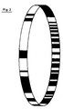
- the code strips are shown projected into the plane, in the device according to the invention the strips are then in a ring as can be seen in FIGS. 2, 3 and 4.
- FIG. 3b A projection into the side view is shown in FIG. 3b.
- h denotes the height of the ring.
- the attachment of the device with a ring is adapted to the particular circumstances of the steering wheel and the installation space and is not shown here.
- FIG. 4 shows schematically a fork light barrier 1 through which the ring 2 provided with a bar code runs.
- Transmitter 4 and receiver 6 of the light beams are housed in a common housing 8.
- the required number of sensors of this type is evenly distributed in the fixed part of the steering and arranged so that the ring bearing the bar code can engage in the forks of the sensors.
- the height of the strips ensures reliable reading even when the installation tolerances are used.
- the fork light barrier 1 is with an evaluation unit 16 connected to calculate the angle of rotation.
- FIG. 5 shows the device 10 according to the invention installed in a steering wheel 12 with a steering column 14. It can be seen that the ring 2 with the bar code is arranged parallel to the steering column 14. The required sensors can be arranged outside of the ring 2 and, given the installation conditions, also inside the ring 2.
- the device according to the invention enables absolute detection of the angle of rotation without counting errors.
- the evaluation system is immediately ready for operation and there is no angular error after the operating voltage fails. It is also possible to carry out a plausibility check of the determined angles by means of a microprocessor.
- the angular coding on one track enables installation in the existing installation space, whereby large tolerances in the axial direction are tolerated.
- Faulty sensors can be detected by software using a microprocessor and, if necessary, the incorrectly determined value can be corrected. If an increase in measuring accuracy is required, in contrast to the known gray code methods, no further code track is required, but only a change in the bit serial code on the ring and possibly an increase in the number of sensor elements.
Description
Die Erfindung betrifft eine Vorrichtung zur Bestimmung des Drehwinkels eines Fahrzeuglenkrades mit einem lenkradseitig angeordneten Ring, welcher eine einspurige Streifenstruktur mit zur Lenksäule parallelen Streifen aufweist, sowie mit einer außerhalb bzw. innerhalb des Ringes angeordneten stationären Sensoranordnung, die mit dem Streifen zur Drehwinkelbestimmung zusammenwirkt.The invention relates to a device for determining the angle of rotation of a vehicle steering wheel with a ring arranged on the steering wheel side, which has a single-lane strip structure with strips parallel to the steering column, and with a stationary sensor arrangement arranged outside or inside the ring, which interacts with the strip for determining the angle of rotation.
Bei einer aus der GB-A 2024122 bekannten derartigen Vorrichtung ist das Lenkrad antriebsmäßig mit einem zur Lenkwelle konzentrischen Teller od.dgl. verbunden, an dem ein Stirnverzahnungsring angeordnet ist, der seinerseits mit einer stationären Sensoranordnung zusammenwirkt. Die Zähne des Stellverzahnungsringes bilden zusammen mit den Zahnlücken eine Streifenstruktur mit zur Lenksäule parallelen Streifen. Bei Drehung des Lenkrades laufen die Zähne des Stirnverzahnungsringes (bzw. die Lücken zwischen den Zähnen) an der Sensoranordnung vorbei, welche als Lichtschrankensensor ausgebildet sein kann. Je nachdem, ob sich einer der Zähne oder eine Zahnlücke im Lichtweg befindet, wird der Lichtweg freigegeben oder unterbrochen. Damit kann aus der Zahl der bei einer Lenkraddrehung an der Sensoranordnung vorbeilaufenden Zähne auf die Größe der Winkelverzahnung des Lenkrades geschlossen werden.In a device of this type known from GB-A 2024122, the steering wheel is drive-like or similar with a plate concentric with the steering shaft. connected, on which a spur gear ring is arranged, which in turn interacts with a stationary sensor arrangement. The teeth of the adjusting toothing ring, together with the tooth gaps, form a strip structure with strips parallel to the steering column. When the steering wheel rotates, the teeth of the spur gear ring (or the gaps between the teeth) run past the sensor arrangement, which can be designed as a light barrier sensor. Depending on whether one of the teeth or a tooth gap is in the light path, the light path is released or interrupted. This can be done from the number of the sensor arrangement during a steering wheel rotation passing teeth can be concluded on the size of the angular toothing of the steering wheel.
Bei dieser bekannten Vorrichtung erfolgt also die Drehwinkelbestimmung durch die Zählung von Streifen (Zähne oder Zahnlücken des Stirnverzahnungsrades). Dies hat zur Folge, daß der jeweils ermittelte Wert des Drehwinkels "vergessen" werden kann, wenn die Energieversorgung der Vorrichtung eine Störung aufweist bzw. von der Vorrichtung abgekoppelt wird.In this known device, the rotation angle is determined by counting strips (teeth or tooth gaps of the spur gear). The result of this is that the respectively determined value of the angle of rotation can be "forgotten" if the energy supply to the device has a fault or is decoupled from the device.
Im übrigen ist bei der bekannten Vorrichtung notwendig, daß der Stirnverzahnungsring bezüglich der Sensoranordnung relativ genau justiert angeordnet wird, um eine fehlerfreie Zählung der Zähne bzw. Zahnlücken durch die Sensoranordnung zu ermöglichen.For the rest, it is necessary in the known device that the spur gear ring is arranged relatively precisely adjusted with respect to the sensor arrangement in order to enable error-free counting of the teeth or tooth gaps by the sensor arrangement.
Aufgabe der Erfindung ist es nun, zur Bestimmung des Drehwinkels eines Fahrzeuglenkrades eine Vorrichtung zu schaffen, welche sich durch besonders hohe Betriebssicherheit auszeichnet, wobei insbesondere gewährleistet sein soll, daß Unterbrechungen einer elektrischen Betriebsspannung sowie eventuelle Toleranzen bei der Montage zu keinerlei Fehlern bei der Drehwinkelermittlung führen können.The object of the invention is to provide a device for determining the angle of rotation of a vehicle steering wheel, which is characterized by particularly high operational reliability, with particular care being taken to ensure that interruptions in an electrical operating voltage and any tolerances during assembly do not lead to any errors in determining the angle of rotation can.
Diese Aufgabe wird erfindungsgemäß dadurch gelöst, daß die Sensoranordnung mehrfach, in Winkelabständen angeordnete Sensoren aufweist und die Streifenstruktur einen solchen Code bildet, der im Zusammenwirken mit den Sensoren eine Absolutwerterkennung ermöglicht, und daß die Streifen ― in Parallelrichtung zur Lenksäule ― eine solche Höhe besitzen, daß auch bei Ausnutzung von Einbautoleranzen ein sicheres Zusammenwirken mit den Sensoren gewährleistet ist. Die Erfindung läßt sich in einfacher Weise konstruktiv verwirklichen, wie nachfolgend beispielhaft erläutert wird.This object is achieved in that the sensor arrangement has multiple, angularly spaced sensors and the stripe structure forms such a code that, in cooperation with the sensors, enables absolute value detection, and that the stripes have such a height - in parallel to the steering column. that a safe interaction with the sensors is guaranteed even when using installation tolerances. The invention can be implemented constructively in a simple manner, as will be explained below by way of example.
Am vorgegebenen Lenkrad wird eine Vorrichtung mit umlaufenden Ring vorgesehen und befestigt, wobei der Ring parallel zur Lenksäule ausgebildet ist. In diesen Ring ist der auf die Auflösung angepasste Streifencode vorzugsweise durch Aussparungen in vorgegebener Breite eingearbeitet. So ist dort eine Aussparung vorgesehen, wo der digitale Code eine "0" vorsieht und bei einer "1" ist der Ring erhalten geblieben.A device with a circumferential ring is provided and fastened to the specified steering wheel, the ring being designed parallel to the steering column. The strip code adapted to the resolution is preferably incorporated into this ring by cutouts of a predetermined width. A recess is provided where the digital code is Provides "0" and the ring is retained at "1".
Bei einer Auflösung kleiner als 1 Grad ist eine Mindestanzahl von neun Sensoren erforderlich. Um beispielsweise auf eine Winkelauflösung von 0,8 Grad zu kommen, ergibt sich eine Unterteilung des Kreises in 450 Teilstücke. Die Sensoren sind bei der Verwendung eines Streifencodes mit Hilfe von Aussparungen als Gabellichtschranken ausgebildet, wobei der Lichtspalt kleiner als die gewünschte Auflösung ist. Diese Sensoren sind auf dem festen Teil der Lenkung in gleichen Winkelabständen so angeordnet, dass der Ring mit den Aussparungen in die Lichtschrankengabeln eingreifen kann.If the resolution is less than 1 degree, a minimum number of nine sensors is required. To get an angular resolution of 0.8 degrees, for example, the circle is divided into 450 sections. When using a bar code, the sensors are designed as fork light barriers with the aid of cutouts, the light gap being smaller than the desired resolution. These sensors are arranged on the fixed part of the steering at equal angular intervals so that the ring with the cutouts can engage in the light barrier forks.
Ein Verschmutzen der Aussparungen tritt nicht auf und durch die Länge der Aussparung parallel zur Lenksäule ist gewährleistet, dass auch bei Ausnutzung der Einbautoleranzen des Lenkrades immer eine sichere Anzeige möglich ist. Neben de vorzugsweise vorgeschlagenen Ausgestaltung des Streifencodes mit Hilfe von Aussparungen lassen sich die Streifencodes auch mit einem Reflexkoppler erkennen. Dabei werden statt der Aussparungen reflektierende Streifen entsprechender Breite auf dem Ring vorgesehen. Auf diese Streifen werden Lichtstrahlen gerichtet und durch die Reflexion des Lichts auf das Vorhandensein einer "1" oder "0" geschlossen.Soiling of the recesses does not occur and the length of the recess parallel to the steering column ensures that a reliable display is always possible even when the installation tolerances of the steering wheel are used. In addition to the preferably proposed configuration of the bar code with the aid of cutouts, the bar codes can also be recognized with a reflex coupler. Instead of the cutouts, reflective strips of corresponding width are provided on the ring. Light rays are directed onto these strips and the presence of a "1" or "0" is inferred from the reflection of the light.
Denkbar und besonders vorteilhaft, da sehr hoch auflösend, ist die Verwendung von CCD-Zeilenkameras. Mit ihnen lassen sich auf dem Ring der am Lenkrad angebrachten Vorrichtung Streifencodes mit einer sehr hohen Auflösung erkennen. Optische Erkennungsverfahren sind gegenüber induktiv, kapazitiv oder mit Ultraschall arbeitenden Systemen dahingehend vorteilhaft, dass sie mit einer höheren Genauigkeit arbeiten und damit eine feinere Unterteilung und Auflösung gewährleisten. Die von den Sensoren gewonnenen Signale werden einer Auswerteschaltung zugeführt, die den Lenkwinkel errechnet.The use of CCD line scan cameras is conceivable and particularly advantageous, since it has a very high resolution. They can be used to recognize bar codes with a very high resolution on the ring of the device attached to the steering wheel. Optical detection methods are advantageous compared to inductive, capacitive or ultrasound systems in that they are more accurate work and thus ensure a finer subdivision and resolution. The signals obtained from the sensors are fed to an evaluation circuit that calculates the steering angle.
Mit der zuvor beschriebenen Vorrichtung lässt sich der Drehwinkel einer Lenkradumdrehung sehr genau bestimmen. In Kraftfahrzeugen ist jedoch regelmäßig ein Lenkraddrehwinkel von bis zu ± 600 Grad vorgesehen. Das Lenkrad muß mehrfach gedreht werden, um vom maximalen linken zum maximalen rechten Lenkanschlag zu gelangen. Zur Detektion der Umdrehungsanzahl sind verschiedene Lösungen möglich. Vorzugsweise wird ein zusätzlicher, induktiv arbeitender Sensor "hinter" dem Lenkgetriebe angeordnet, der die Anzahl der Lenkradumdrehungen erkennt. Er muß einen Zusammenhang zwischen dem Lenkraddrehwinkel und dem Lenkwinkel erzeugen, damit erkannt wird, in welcher Lenkradumdrehung der Lenkraddrehwinkel gerade entsteht.With the device described above, the angle of rotation of a steering wheel revolution can be determined very precisely. In motor vehicles, however, a steering wheel rotation angle of up to ± 600 degrees is regularly provided. The steering wheel must be turned several times to get from the maximum left to the maximum right steering stop. Various solutions are possible for the detection of the number of revolutions. An additional, inductively operating sensor is preferably arranged "behind" the steering gear, which detects the number of turns of the steering wheel. He must create a relationship between the steering wheel rotation angle and the steering angle, so that it can be recognized in which steering wheel rotation the steering wheel rotation angle is currently occurring.
Eine andere Lösung besteht darin, mit Hilfe der Auswerteeinrichtung für den Lenkraddrehwinkel auch die Anzal der Umdrehungen des Lenkrades mitzuzählen. Bei einem Versorgungsspannungsausfall muß die Lenkwinkelmittelstellung wieder neu einjustiert werden, was sich aber über statistische Verfahren errechnen lässt oder die Lenkradextremeinstellungen links und rechts werden mit je einem Taster der Auswerteeinheit mitgeteilt.Another solution is to count the number of revolutions of the steering wheel with the aid of the evaluation device for the steering wheel rotation angle. In the event of a supply voltage failure, the steering angle middle position must be readjusted, but this can be calculated using statistical methods or the extreme steering wheel settings on the left and right are communicated to the evaluation unit with one button each.
Die Erfindung wird anhand von Figuren näher erläutert.The invention is explained in more detail with reference to figures.
Es zeigen:
Figur 1- eine Codescheibe mit einspurigem Code,
Figur 2- den Streifencode als Ring,
- Figur 3a
- den Ring der Vorrichtung am Lenkrad in Draufsicht,
- Figur 3b
- den Ring in Seitenansicht,
Figur 4- schematisch den Ring in einer Gabellichtschranke und
Figur 5- die eingebaute Vorrichtung am Lenkrad.
Show it:
- Figure 1
- a code disk with single-track code,
- Figure 2
- the bar code as a ring,
- Figure 3a
- the ring of the device on the steering wheel in top view,
- Figure 3b
- the ring in side view,
- Figure 4
- schematically the ring in a fork light barrier and
- Figure 5
- the built-in device on the steering wheel.
Die Figur 1 zeigt eine Codescheibe für eine Auflösung von 0,8 Grad und eine Unterteilung in 450 Schritte. Für die Ablesung der Codestreifen sind neun Sensoren erforderlich, die im Winkel von 40 Grad angeordnet sind. Hier sind die Codestreifen in die Ebene projiziert dargestellt, in der erfindungsgemässen Vorrichtung befinden sich die Streifen dann in einem Ring wie in den Figuren 2, 3 und 4 erkennbar.FIG. 1 shows a code disk for a resolution of 0.8 degrees and a division into 450 steps. To read the code strips, nine sensors are required, which are arranged at an angle of 40 degrees. Here the code strips are shown projected into the plane, in the device according to the invention the strips are then in a ring as can be seen in FIGS. 2, 3 and 4.
In Figur 3a ist der Ring in Draufsicht mit Aussendurchmesser D und Innendurchmesser d dargestellt.In Figure 3a, the ring is shown in plan view with outer diameter D and inner diameter d.
Eine Projektion in die Seitenansicht stellt Figur 3b dar. Dabei kennzeichnet h die Höhe des Ringes.A projection into the side view is shown in FIG. 3b. Here, h denotes the height of the ring.
Die Befestigung der Vorrichtung mit Ring ist den jeweiligen Gegebenheiten des Lenkrades und des Einbauraumes angepasst und hier nicht gezeigt.The attachment of the device with a ring is adapted to the particular circumstances of the steering wheel and the installation space and is not shown here.
Figur 4 zeigt schematisch eine Gabellichtschranke 1, durch die der mit Streifencode versehene Ring 2 läuft. Sender 4 und Empfänger 6 der Lichtstrahlen sind in einem gemeinsamen Gehäuse 8 untergebracht. Die erforderliche Anzahl an Sensoren dieser Art ist im feststehenden Teil der Lenkung gleichmässig verteilt und so angeordnet, dass der den Streifencode tragende Ring in die Gabeln der Sensoren eingreifen kann. Durch die Höhe der Streifen ist ein sicheres Ablesen auch bei Ausnutzung der Einbautoleranzen gewährleistet. Die Gabellichtschranke 1 ist mit einer Auswerteeinheit 16 zur Berechnung der Drehwinkel verbunden.FIG. 4 shows schematically a fork
Figur 5 zeigt die erfindungsgemässe Vorrichtung 10 in einem Lenkrad 12 mit Lenksäule 14 eingebaut. Dabei ist zu erkennen, dass der Ring 2 mit dem Streifencode parallel zur Lenksäule 14 angeordnet ist. Die erforderliche Sensoren können ausserhalb des Ringes 2, bei gegebenen Einbauverhältnissen auch innerhalb des Ringes 2 angeordnet sein.FIG. 5 shows the
Die erfindungsgemässe Vorrichtung ermöglicht eine Absoluterkennung des Drehwinkels ohne Zählfehler. Das Auswertesystem ist sofort betriebsbereit und es bleibt kein Winkelfehler nach Ausfall der Betriebsspannung. Möglich ist auch, eine Plausibilitätskontrolle der ermittelten Winkel durch einen Mikroprozessor vorzunehmen. Die Winkelcodierung auf einer Spur ermöglicht den Einbau in den vorhandenen Bauraum, wobei grosse Toleranzen in axialer Richtung toleriert werden.The device according to the invention enables absolute detection of the angle of rotation without counting errors. The evaluation system is immediately ready for operation and there is no angular error after the operating voltage fails. It is also possible to carry out a plausibility check of the determined angles by means of a microprocessor. The angular coding on one track enables installation in the existing installation space, whereby large tolerances in the axial direction are tolerated.
Fehlerhafte Sensoren können durch einen Mikroprozessor softwaremässig erkannt und gegebenenfalls der fehlerhaft ermittelte Wert korrigiert werden. Wird eine Erhöhung der Meßgenauigkeit gefordert, so ist im Gegensatz zu den bekannten Graycode-Verfahren keine weitere Codespur, sondern nur eine Veränderung des bitseriellen Codes auf dem Ring und eventuell eine Erhöhung der Anzahl der Sensorelemente erforderlich.Faulty sensors can be detected by software using a microprocessor and, if necessary, the incorrectly determined value can be corrected. If an increase in measuring accuracy is required, in contrast to the known gray code methods, no further code track is required, but only a change in the bit serial code on the ring and possibly an increase in the number of sensor elements.
Claims (13)
Applications Claiming Priority (2)
| Application Number | Priority Date | Filing Date | Title |
|---|---|---|---|
| DE3837111 | 1988-11-02 | ||
| DE3837111 | 1988-11-02 |
Publications (2)
| Publication Number | Publication Date |
|---|---|
| EP0377097A1 EP0377097A1 (en) | 1990-07-11 |
| EP0377097B1 true EP0377097B1 (en) | 1992-01-29 |
Family
ID=6366278
Family Applications (1)
| Application Number | Title | Priority Date | Filing Date |
|---|---|---|---|
| EP89120231A Expired - Lifetime EP0377097B1 (en) | 1988-11-02 | 1989-11-01 | Steering angle sensor for a motor vehicle |
Country Status (3)
| Country | Link |
|---|---|
| EP (1) | EP0377097B1 (en) |
| DE (1) | DE58900804D1 (en) |
| ES (1) | ES2030254T3 (en) |
Cited By (11)
| Publication number | Priority date | Publication date | Assignee | Title |
|---|---|---|---|---|
| DE19506019A1 (en) * | 1995-02-22 | 1996-09-05 | Telefunken Microelectron | Operating optical steering angle stationary sensor with several optical elements |
| DE19638911A1 (en) * | 1996-09-23 | 1998-03-26 | Teves Gmbh Alfred | Rotation angle sensor for motor vehicle |
| DE19638912A1 (en) * | 1996-09-23 | 1998-03-26 | Teves Gmbh Alfred | Position sensor arrangement for rotation angle sensor in motor vehicle |
| DE19647705A1 (en) * | 1996-11-11 | 1998-05-20 | Petri Ag | Device for determining the angular position of the steering wheel in a motor vehicle |
| DE19712869A1 (en) * | 1997-03-27 | 1998-10-01 | Itt Mfg Enterprises Inc | Steering angle sensor system with increased redundancy |
| DE19716321C1 (en) * | 1997-04-18 | 1998-10-15 | Kostal Leopold Gmbh & Co Kg | Sensor for indexing angle of rotation e.g. of steering column |
| DE19812842A1 (en) * | 1998-03-24 | 1999-09-30 | Bosch Gmbh Robert | System for determining steering wheel revolutions with transmitting elements arranged at steering wheel reflecting or self transmitting several IR or electromagnetic beams |
| DE19836666C1 (en) * | 1998-08-13 | 2000-02-17 | Kostal Leopold Gmbh & Co Kg | Steering angle sensor, e.g. for automobile stability control; has sensor unit for limited angular range and sensor unit for full rotation range positioned on opposite sides of common circuit board |
| DE19926278C1 (en) * | 1999-06-09 | 2001-02-15 | Kostal Leopold Gmbh & Co Kg | Device for transmitting energy |
| DE102010016684A1 (en) * | 2010-04-29 | 2011-11-03 | Sartorius Ag | Fork light barrier, device and method for determining position by means of a fork light barrier |
| WO2017069642A1 (en) | 2015-10-23 | 2017-04-27 | Boba Bartlomiej | Method and system for determining the position of steering wheel in mechanical vehicles |
Families Citing this family (18)
| Publication number | Priority date | Publication date | Assignee | Title |
|---|---|---|---|---|
| DE4228719A1 (en) * | 1992-08-28 | 1994-03-03 | Schaeffler Waelzlager Kg | Capacitive steering angle sensor for motor vehicle - forms first capacitor group from electronics transmitter electrodes and scale receiver electrodes, and second capacitor group from scale transmitter electrodes and electronics receiver electrodes |
| SE502358C2 (en) * | 1993-09-24 | 1995-10-09 | Nira Automotive Ab | Steering angle sensor for a motor vehicle |
| US5471202A (en) * | 1994-02-25 | 1995-11-28 | Samsung Heavy Ind. Co. Ltd. | Rotation sensing device for detecting a fine displacement of a handle and control system in electrical power steering device |
| DE4409892A1 (en) * | 1994-03-23 | 1995-09-28 | Bosch Gmbh Robert | Steering angle sensor |
| DE4431238A1 (en) * | 1994-09-02 | 1996-03-14 | Moto Meter Gmbh | Stepper motor with position sensor |
| DE19532903A1 (en) * | 1995-09-07 | 1997-03-13 | Teves Gmbh Alfred | Steering angle sensor with absolute value measurement |
| EP0774648B1 (en) * | 1995-11-17 | 2000-07-12 | Leopold Kostal GmbH & Co. KG | Angle sensor |
| DE19601676A1 (en) * | 1996-01-18 | 1997-07-24 | Teves Gmbh Alfred | Steering angle sensor with evaluation of the incremental track for absolute value determination |
| US6483104B1 (en) | 1996-09-23 | 2002-11-19 | Valeo Schalter Und Sensoren Gmbh | Rotational angle sensor using a CCD line with enhanced measuring precision |
| AUPP482598A0 (en) * | 1998-07-24 | 1998-08-13 | Bishop Innovation Pty Limited | Angle encoder |
| DE19739104C2 (en) * | 1997-09-06 | 2000-12-21 | Trw Automotive Safety Sys Gmbh | Steering device with transmitter |
| DE59803570D1 (en) * | 1997-12-18 | 2002-05-02 | Takata Petri Ag | ADAPTIVE ABSOLUTE STEERING ANGLE SENSOR |
| DE10040372A1 (en) * | 2000-08-18 | 2002-02-28 | Valeo Schalter & Sensoren Gmbh | Method, computer program and device for determining the steering angle of a vehicle steering system |
| DE102005055906A1 (en) * | 2005-11-22 | 2007-05-31 | Borg Instruments Ag | Ring display instrument for e.g. car, has bright/dark indication and sensor e.g. radiation sensor, that are arranged on ring, where position of pointer within instrument is detected using bright/dark indication |
| IL183471A0 (en) | 2007-05-28 | 2007-09-20 | Yaskawa Europ Technology Ltd | Absolute encoder |
| DE102009009788B4 (en) | 2009-02-20 | 2019-12-19 | Phoenix Contact Gmbh & Co. Kg | Device and method for the contactless determination of a rotational angle position and / or a standstill of a rotatable object |
| DE102012023479B4 (en) * | 2012-11-29 | 2019-06-06 | Audi Ag | Device for marking the steering wheel center position on a steering shaft and method for installing steering shaft and steering wheel in a motor vehicle |
| CN110375776B (en) * | 2019-07-25 | 2021-05-11 | 广东工业大学 | Rotary encoder |
Family Cites Families (6)
| Publication number | Priority date | Publication date | Assignee | Title |
|---|---|---|---|---|
| DE1928613A1 (en) * | 1969-01-27 | 1970-07-30 | Radebeul Rapido Waegetechnik | Method and device for digital distance and angle measurement |
| GB2024122B (en) * | 1978-06-30 | 1982-09-22 | Towmotor Corp | Steering wheel assembly |
| DE3119414C2 (en) * | 1981-05-15 | 1983-04-07 | Audi Nsu Auto Union Ag, 7107 Neckarsulm | Electromagnetic signal generator for measuring the angular position of a rotating component |
| JPS59117911U (en) * | 1983-01-29 | 1984-08-09 | トヨタ自動車株式会社 | car steering column |
| DE3423664A1 (en) * | 1984-06-27 | 1986-01-09 | Robert Bosch Gmbh, 7000 Stuttgart | DEVICE FOR ANGULAR POSITION DETECTION OF A ROTATING PART |
| FR2595461B1 (en) * | 1986-03-04 | 1991-08-16 | Peugeot | METHOD FOR ANGULAR MARKING OF A ROTATING MACHINE |
-
1989
- 1989-11-01 ES ES198989120231T patent/ES2030254T3/en not_active Expired - Lifetime
- 1989-11-01 DE DE8989120231T patent/DE58900804D1/en not_active Revoked
- 1989-11-01 EP EP89120231A patent/EP0377097B1/en not_active Expired - Lifetime
Cited By (17)
| Publication number | Priority date | Publication date | Assignee | Title |
|---|---|---|---|---|
| DE19506019C2 (en) * | 1995-02-22 | 2000-04-13 | Telefunken Microelectron | Method for operating an optical steering angle sensor |
| DE19506019A1 (en) * | 1995-02-22 | 1996-09-05 | Telefunken Microelectron | Operating optical steering angle stationary sensor with several optical elements |
| DE19638911A1 (en) * | 1996-09-23 | 1998-03-26 | Teves Gmbh Alfred | Rotation angle sensor for motor vehicle |
| DE19638912A1 (en) * | 1996-09-23 | 1998-03-26 | Teves Gmbh Alfred | Position sensor arrangement for rotation angle sensor in motor vehicle |
| DE19638911B4 (en) * | 1996-09-23 | 2006-10-05 | Valeo Schalter Und Sensoren Gmbh | Angle of rotation sensor with integrated revolution detection |
| DE19647705A1 (en) * | 1996-11-11 | 1998-05-20 | Petri Ag | Device for determining the angular position of the steering wheel in a motor vehicle |
| DE19647705C2 (en) * | 1996-11-11 | 1998-10-08 | Petri Ag | Device for determining the angular position of the steering wheel in a motor vehicle |
| US6236119B1 (en) | 1996-11-11 | 2001-05-22 | Petri Ag | Device for determining the angular position of the steering wheel in a motor vehicle |
| DE19712869A1 (en) * | 1997-03-27 | 1998-10-01 | Itt Mfg Enterprises Inc | Steering angle sensor system with increased redundancy |
| DE19716321C1 (en) * | 1997-04-18 | 1998-10-15 | Kostal Leopold Gmbh & Co Kg | Sensor for indexing angle of rotation e.g. of steering column |
| DE19812842C2 (en) * | 1998-03-24 | 2000-06-29 | Bosch Gmbh Robert | Device for detecting steering wheel rotations |
| DE19812842A1 (en) * | 1998-03-24 | 1999-09-30 | Bosch Gmbh Robert | System for determining steering wheel revolutions with transmitting elements arranged at steering wheel reflecting or self transmitting several IR or electromagnetic beams |
| DE19836666C1 (en) * | 1998-08-13 | 2000-02-17 | Kostal Leopold Gmbh & Co Kg | Steering angle sensor, e.g. for automobile stability control; has sensor unit for limited angular range and sensor unit for full rotation range positioned on opposite sides of common circuit board |
| DE19926278C1 (en) * | 1999-06-09 | 2001-02-15 | Kostal Leopold Gmbh & Co Kg | Device for transmitting energy |
| DE102010016684A1 (en) * | 2010-04-29 | 2011-11-03 | Sartorius Ag | Fork light barrier, device and method for determining position by means of a fork light barrier |
| WO2011134560A1 (en) | 2010-04-29 | 2011-11-03 | Sartorius Weighing Technology Gmbh | Fork light barrier, and device and method for determining position by means of a fork light barrier |
| WO2017069642A1 (en) | 2015-10-23 | 2017-04-27 | Boba Bartlomiej | Method and system for determining the position of steering wheel in mechanical vehicles |
Also Published As
| Publication number | Publication date |
|---|---|
| EP0377097A1 (en) | 1990-07-11 |
| ES2030254T3 (en) | 1992-10-16 |
| DE58900804D1 (en) | 1992-03-12 |
Similar Documents
| Publication | Publication Date | Title |
|---|---|---|
| EP0377097B1 (en) | Steering angle sensor for a motor vehicle | |
| EP0970000B1 (en) | Steering angle sensor system with enhanced redundancy | |
| DE4009007C2 (en) | Method for detecting the absolute steering angle of a steering angle sensor for a vehicle | |
| EP0953494B1 (en) | Apparatus for sensing the amount of torsion between two parts | |
| DE3908854C2 (en) | ||
| EP1157256B1 (en) | Length measurement system with at least one magnetic measuring rod | |
| EP0699151A1 (en) | Steering angle detection sensor | |
| DE102004002722B4 (en) | Absolute encoder based on an incremental encoder | |
| WO2005068962A1 (en) | Device for determining a steering angle and a torque that is exerted on a steering shaft | |
| EP0848804A1 (en) | Steering-angle sensor giving absolute values | |
| EP1982147A1 (en) | Rotation angle sensor and method for determining the absolute angular position of a body that undergoes several revolutions | |
| EP3350545A1 (en) | Steering angle sensor with functional security | |
| EP1180665A2 (en) | Steering angle sensor for motor vehicles | |
| DE4008106A1 (en) | METHOD AND DEVICE FOR DETERMINING FAULTS OF A VEHICLE STEERING SENSOR DEVICE | |
| DE3605654C2 (en) | ||
| DE19746115A1 (en) | clockwork | |
| EP0902255B1 (en) | Angle sensor | |
| DE4115244C2 (en) | Angle sensor for determining the rotational position of a steering shaft of a motor vehicle | |
| EP1770375B1 (en) | Position measuring device with two scales whose coded tracks overlap one another | |
| EP1312534A2 (en) | Steering wheel steering angle determination apparatus | |
| DE102012023980B4 (en) | Method and device for verifying a first relative position by means of a second relative position | |
| DE19860504B4 (en) | Absolute-angle sensor of a vehicle steering system | |
| DE102020108981A1 (en) | Sensor arrangement for detecting the absolute angular position of a steering element | |
| EP0941454B1 (en) | Absolute value sensor, in particular rotation sensor for sensing the steering angle of a motor vehicle | |
| DE202018106310U1 (en) | Optoelectronic sensor |
Legal Events
| Date | Code | Title | Description |
|---|---|---|---|
| PUAI | Public reference made under article 153(3) epc to a published international application that has entered the european phase |
Free format text: ORIGINAL CODE: 0009012 |
|
| AK | Designated contracting states |
Kind code of ref document: A1 Designated state(s): DE ES FR GB IT SE |
|
| RIN1 | Information on inventor provided before grant (corrected) |
Inventor name: ULKE, WALTER, DIPL.-ING. Inventor name: LUETHIN, UWE Inventor name: ADOMAT, ROLF, DIPL.-ING. Inventor name: SCHNELL, JOSEF Inventor name: SCHMITFRANZ, BERND-HEINRICH, DIPL.-ING. (FH) Inventor name: KAMINSKI, DETLEF, DIPL.-ING. |
|
| 17P | Request for examination filed |
Effective date: 19910108 |
|
| 17Q | First examination report despatched |
Effective date: 19910417 |
|
| GRAA | (expected) grant |
Free format text: ORIGINAL CODE: 0009210 |
|
| AK | Designated contracting states |
Kind code of ref document: B1 Designated state(s): DE ES FR GB IT SE |
|
| ITF | It: translation for a ep patent filed |
Owner name: BARZANO' E ZANARDO ROMA S.P.A. |
|
| GBT | Gb: translation of ep patent filed (gb section 77(6)(a)/1977) | ||
| REF | Corresponds to: |
Ref document number: 58900804 Country of ref document: DE Date of ref document: 19920312 |
|
| ET | Fr: translation filed | ||
| PLBI | Opposition filed |
Free format text: ORIGINAL CODE: 0009260 |
|
| REG | Reference to a national code |
Ref country code: ES Ref legal event code: FG2A Ref document number: 2030254 Country of ref document: ES Kind code of ref document: T3 |
|
| 26 | Opposition filed |
Opponent name: ROBERT BOSCH GMBH Effective date: 19920929 |
|
| PGFP | Annual fee paid to national office [announced via postgrant information from national office to epo] |
Ref country code: ES Payment date: 19931122 Year of fee payment: 5 |
|
| PGFP | Annual fee paid to national office [announced via postgrant information from national office to epo] |
Ref country code: SE Payment date: 19931220 Year of fee payment: 5 |
|
| PGFP | Annual fee paid to national office [announced via postgrant information from national office to epo] |
Ref country code: GB Payment date: 19931223 Year of fee payment: 5 |
|
| PGFP | Annual fee paid to national office [announced via postgrant information from national office to epo] |
Ref country code: DE Payment date: 19931224 Year of fee payment: 5 |
|
| PGFP | Annual fee paid to national office [announced via postgrant information from national office to epo] |
Ref country code: FR Payment date: 19931230 Year of fee payment: 5 |
|
| RDAG | Patent revoked |
Free format text: ORIGINAL CODE: 0009271 |
|
| STAA | Information on the status of an ep patent application or granted ep patent |
Free format text: STATUS: PATENT REVOKED |
|
| 27W | Patent revoked |
Effective date: 19931206 |
|
| GBPR | Gb: patent revoked under art. 102 of the ep convention designating the uk as contracting state |
Free format text: 931206 |
|
| EUG | Se: european patent has lapsed |
Ref document number: 89120231.9 Effective date: 19940518 |