EP0376703A2 - Engine control system - Google Patents
Engine control system Download PDFInfo
- Publication number
- EP0376703A2 EP0376703A2 EP89313622A EP89313622A EP0376703A2 EP 0376703 A2 EP0376703 A2 EP 0376703A2 EP 89313622 A EP89313622 A EP 89313622A EP 89313622 A EP89313622 A EP 89313622A EP 0376703 A2 EP0376703 A2 EP 0376703A2
- Authority
- EP
- European Patent Office
- Prior art keywords
- engine
- capacity
- supercharge
- condition
- control
- Prior art date
- Legal status (The legal status is an assumption and is not a legal conclusion. Google has not performed a legal analysis and makes no representation as to the accuracy of the status listed.)
- Granted
Links
Images


Classifications
-
- F—MECHANICAL ENGINEERING; LIGHTING; HEATING; WEAPONS; BLASTING
- F02—COMBUSTION ENGINES; HOT-GAS OR COMBUSTION-PRODUCT ENGINE PLANTS
- F02B—INTERNAL-COMBUSTION PISTON ENGINES; COMBUSTION ENGINES IN GENERAL
- F02B37/00—Engines characterised by provision of pumps driven at least for part of the time by exhaust
- F02B37/12—Control of the pumps
- F02B37/24—Control of the pumps by using pumps or turbines with adjustable guide vanes
-
- F—MECHANICAL ENGINEERING; LIGHTING; HEATING; WEAPONS; BLASTING
- F01—MACHINES OR ENGINES IN GENERAL; ENGINE PLANTS IN GENERAL; STEAM ENGINES
- F01L—CYCLICALLY OPERATING VALVES FOR MACHINES OR ENGINES
- F01L1/00—Valve-gear or valve arrangements, e.g. lift-valve gear
- F01L1/26—Valve-gear or valve arrangements, e.g. lift-valve gear characterised by the provision of two or more valves operated simultaneously by same transmitting-gear; peculiar to machines or engines with more than two lift-valves per cylinder
- F01L1/267—Valve-gear or valve arrangements, e.g. lift-valve gear characterised by the provision of two or more valves operated simultaneously by same transmitting-gear; peculiar to machines or engines with more than two lift-valves per cylinder with means for varying the timing or the lift of the valves
-
- F—MECHANICAL ENGINEERING; LIGHTING; HEATING; WEAPONS; BLASTING
- F02—COMBUSTION ENGINES; HOT-GAS OR COMBUSTION-PRODUCT ENGINE PLANTS
- F02D—CONTROLLING COMBUSTION ENGINES
- F02D13/00—Controlling the engine output power by varying inlet or exhaust valve operating characteristics, e.g. timing
- F02D13/02—Controlling the engine output power by varying inlet or exhaust valve operating characteristics, e.g. timing during engine operation
- F02D13/0203—Variable control of intake and exhaust valves
- F02D13/0207—Variable control of intake and exhaust valves changing valve lift or valve lift and timing
-
- F—MECHANICAL ENGINEERING; LIGHTING; HEATING; WEAPONS; BLASTING
- F02—COMBUSTION ENGINES; HOT-GAS OR COMBUSTION-PRODUCT ENGINE PLANTS
- F02B—INTERNAL-COMBUSTION PISTON ENGINES; COMBUSTION ENGINES IN GENERAL
- F02B2275/00—Other engines, components or details, not provided for in other groups of this subclass
- F02B2275/18—DOHC [Double overhead camshaft]
-
- F—MECHANICAL ENGINEERING; LIGHTING; HEATING; WEAPONS; BLASTING
- F02—COMBUSTION ENGINES; HOT-GAS OR COMBUSTION-PRODUCT ENGINE PLANTS
- F02D—CONTROLLING COMBUSTION ENGINES
- F02D41/00—Electrical control of supply of combustible mixture or its constituents
- F02D41/0002—Controlling intake air
- F02D2041/001—Controlling intake air for engines with variable valve actuation
-
- F—MECHANICAL ENGINEERING; LIGHTING; HEATING; WEAPONS; BLASTING
- F02—COMBUSTION ENGINES; HOT-GAS OR COMBUSTION-PRODUCT ENGINE PLANTS
- F02D—CONTROLLING COMBUSTION ENGINES
- F02D2200/00—Input parameters for engine control
- F02D2200/50—Input parameters for engine control said parameters being related to the vehicle or its components
- F02D2200/501—Vehicle speed
-
- Y—GENERAL TAGGING OF NEW TECHNOLOGICAL DEVELOPMENTS; GENERAL TAGGING OF CROSS-SECTIONAL TECHNOLOGIES SPANNING OVER SEVERAL SECTIONS OF THE IPC; TECHNICAL SUBJECTS COVERED BY FORMER USPC CROSS-REFERENCE ART COLLECTIONS [XRACs] AND DIGESTS
- Y02—TECHNOLOGIES OR APPLICATIONS FOR MITIGATION OR ADAPTATION AGAINST CLIMATE CHANGE
- Y02T—CLIMATE CHANGE MITIGATION TECHNOLOGIES RELATED TO TRANSPORTATION
- Y02T10/00—Road transport of goods or passengers
- Y02T10/10—Internal combustion engine [ICE] based vehicles
- Y02T10/12—Improving ICE efficiencies
Definitions
- the present invention relates to an engine control system for an engine equipped with a variable valve actuating mechanism, such as a variable valve timing system, and a variable capacity supercharger, such as a turbocharger having moveable vanes to vary the cross sectional area of the exhaust gas passage leading to a turbine wheel, and provides an engine control system which permits the advantages of both a variable valve actuating mechanism and a variable capacity supercharger to be fully utilized by harmonious combination of the two variable elements.
- a variable valve actuating mechanism such as a variable valve timing system
- a variable capacity supercharger such as a turbocharger having moveable vanes to vary the cross sectional area of the exhaust gas passage leading to a turbine wheel
- a valve operation switching unit for improving the volume efficiency of the combustion chambers over a wide operation range by changing at least either the angular interval of opening the intake valves and/or exhaust valves for each cylinder or the lift of the valves is proposed for instance in Japanese patent laid open publication No. 63-16111.
- variable capacity supercharger offering an optimum supercharge pressure over a wide operating range with a high responsiveness by varying the A/R ratio of an exhaust passage leading to a turbine wheel by means of a flap or a plurality of vanes is proposed in Japanese patent laid open publication No. 62-282128.
- variable capacity supercharger since a supercharge pressure which is suitable for each operating condition can be arbitrarily and accurately obtained, an even further improvement can be achieved particularly by combining a valve operating condition switching unit and a variable capacity supercharger.
- a primary object of the present invention is to provide an engine control system which can achieve a maximum improvement in the performance of an engine which incorporates both a variable capacity supercharger and a variable valve actuating unit.
- a second object of the present invention is to provide such an engine control system which combines a fast response and a stable control action.
- a third object of the present invention is to provide such an engine control system which can eliminate the occurrence of a torque dip which may occur if the valve actuating mechanism is varied in step-wise fashion and the rotational speed is increased close to a point of a step-wise varying action.
- a fourth object of the present invention is to provide such an engine control system which is protected from operating in any undesirable fashion even in case of a system failure.
- an engine control system comprising: valve actuating condition varying means for varying a state of a valve actuating mechanism of an engine; capacity varying means for varying a supercharge capacity of a variable capacity supercharger; and control means for controlling a valve actuating condition varying operation of the valve actuating condition varying means and a capacity varying operation of the capacity varying means according to an operating condition including at least a rotational speed of the engine; the control means carrying out the capacity varying operation in dependence upon an operating condition of the valve actuating mechanism.
- an optimum control of supercharge pressure can be accomplished in response to an operating condition of valves.
- the control means increases the supercharge pressure in case of high speed operation of the engine, the high speed performance of the engine can be improved.
- supercharge pressure is decreased according to the increase in the torque output of the engine owing to the switching of the valve operating condition, strain on the engine can be reduced in its high speed operating condition.
- the control means carries out the capacity varying operation of the supercharger by an open loop control process at least when the valve actuating means is adapted for a low speed operating condition of the engine, and by a closed loop control process at least when the valve actuating means is adapted for a high speed operating condition of the engine.
- the open loop control process consists of a map control which determines the supercharge capacity according to a rotational speed of the engine and an opening angle of a throttle valve or an intake negative pressure.
- the control means may change the supercharge pressure of the supercharger at least in a low speed range from a normally controlled level to a boosted level according to a change rate of a level of supercharge pressure, and/or a change rate of a rotational speed of the engine.
- the supercharge pressure output of the supercharger should be increased when a decline in the supercharge pressure is detected as the rotational speed of the engine is increased because such decline in the supercharge pressure means a decline in the volume efficiency of the engine intake, and, in order to remove a torque dip resulting therefrom, the supercharge pressure output of the supercharger should be increased to compensate for the reduction in the volume efficiency.
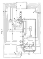
- FIG. 1 shows an overall structure of the intake and exhaust system of an engine to which the present invention is applied.
- this engine main body for instance consisting of an in-line four-cylinder engine
- an intake manifold 3 leading to the intake port 2 of each cylinder is connected to an intake tube 4, a throttle body 5, an intercooler 6, a compressor unit 8 of a variable capacity supercharger 7, and an air cleaner 9, in that order.
- An exhaust manifold 11 leading to the exhaust port 10 of each cylinder is connected to a turbine unit 12 of the variable capacity supercharger 7, and a catalytic converter 13.
- a valve mechanism 14 provided for controlling the intake of mixture and the exhaust of combustion gas into and out of the combustion chamber of each cylinder can change valve timing in a stepwise fashion by controlling hydraulic pressure produced from an oil pump 15 actuated by the engine main body 1, by way of a solenoid valve 16 and a switching control valve 17.
- variable capacity supercharger 7 can continually vary a cross sectional area of a passage for exhaust gas leading to its turbine unit 12 by way of an actuator 18 which is actuated by supercharge pressure P2 immediately downstream of the compressor unit 8 or intake negative pressure immediately downstream of the throttle valve 5 to vary the supercharging capacity of its compressor unit 8.
- This turbocharger 7, along with the intercooler 6, is cooled by cooling water which is circulated by a water pump 19 actuated by the engine main body 1 through a cooling water system including a radiator 20, which is separate from the cooling water system for the engine main body 1.
- the engine 1 is equipped with an electronic control circuit 21 for controlling the amount of fuel injection, valve timing and supercharge pressure for the engine 1.
- the electronic control circuit 21 receives an oil pressure signal O P from an oil pressure switch 22 of a normally closed type provided in the switching control valve 17, an O2 signal from an oxygen concentration sensor 23 provided in the exhaust manifold 11, a rotational speed signal N E from an engine rotational speed sensor 24, a water temperature signal T W from a cooling water temperature sensor 25 provided in the water packet of the engine main body 1, a parking/neutral signal PN indicating the shift position of the automatic transmission system 26 to be either in a parking or neutral range, an intake temperature signal T A and an intake pressure signal P B from an intake temperature sensor 27 and an intake pressure sensor 28, respectively, provided in a part of the intake passage 4a downstream of the throttle body 5, a throttle valve opening angle signal ⁇ TH from a throttle opening angle sensor 29, a supercharge pressure signal P2 from a supercharge pressure sensor 30 provided in a part of the intake passage 4b downstream of the compressor unit 8, an atmospheric pressure signal P A from an atmospheric pressure sensor 31 provided in a part of the intake passage 4c extending between the air cleaner 9 and the compressor unit 8
- Output signals from this electronic control circuit 21 control the operations of solenoid valves for switching over valve timing, fuel injection valves 33 for injecting fuel into the intake ports 2, and solenoid valves 34 and 35 for controlling the supercharge pressure P2 and the intake negative pressure P B for actuating the actuator 18 for varying the supercharger capacity.
- valve actuating mechanism 14 is now described in the following with reference to Figure 2.
- the engine to which the present invention is applied consists of a so-called DOHC engine in which intake valves and exhaust valves are actuated by separate camshafts, and each cylinder is equipped with two intake valves and two exhaust valves. Since the intake valves and the exhaust valves have substantially the same structure, only the part of the valve actutating mechanism 14 related to the intake valve mechanism is described in the following.
- rocker arms 41, 42 and 43 are pivotally supported on a rocker arm shaft 40, which is secured to a cylinder head, adjacent to each other and so as to be rotatable in mutually independent manner.
- a camshaft 45 is rotatably supported by cam journals 44 formed in the cylinder head above the rocker arms 41, 42 and 43.
- the camshaft 45 is provided, for each cylinder, with a pair of low speed cams 46a and 46b having a relatively small angular interval of opening the valves and a relatively small valve lift, and a single high speed cam 47 having a relatively large open valve angular interval and a relatively large valve lift.
- a pair of oil supply tubes 48 and 49 are disposed above the camshaft 45 to lubricate the camshaft 45 and the sliding surfaces between the cams and the rocker arms.
- the free ends of the first and second rocker arms 41 and 42 which engage with the low speed cams 46a and 46b abut the upper ends of the valve stems of a pair of intake valves 50a and 50b which are elastically urged towards their closed positions.
- the third rocker arm 43 disposed between the first and second rocker arms 41 and 42 and engaged with the high speed cam 47 is engaged, at its lower end, with a lost motion spring not shown in the drawing so as to be normally urged upwards.
- the first through third rocker arms 41 through 43 which are disposed one next to the other are internally provided with a coupling switch over unit 51 which consists of a guide bore passed through the rocker arms and switching pins slidably received therein.
- the first rocker arm 41 is provided with a first guide bore 52 having an open end facing the third rocker arm 43 and a closed bottom end and extending in parallel with the rocker arm shaft 40.
- the first guide bore 52 slidably receives a first switching pin 53 therein.
- the bottom end of the first guide bore 52 defines an oil pressure chamber 54 which is communicated with an oil supply passage 57 defined in the hollow rocker arm shaft 40 via an oil passage 55 defined in the first rocker arm 41 and an oil supply opening 56 opening on an outer periphery of the rocker arm shaft 40.
- the third rocker arm 43 is provided with a second guide bore 58 which extends in parallel with the rocker arm shaft 40 and aligns with the first guide bore 52 in a conformal and coaxial manner at its rest position in which its cam slipper engages with a base circle of the high speed cam 47, and a second switching pin 59 is received therein with its one end abutting the first switching pin 53.
- the second rocker arm 42 is likewise provided with a third guide bore 60 having a closed bottom end, and receives a stopper pin 61 therein with its one end abutting the other end of the second switching pin 59.
- the stopper pin 61 has a stem portion 63 which is received in a guide sleeve 62 fitted into the bottom end of the third guide bore 60, and is normally elastically urged towards the third rocker arm 43 by a return spring 64.
- the downstream end of the oil supply passage 57 internally provided in the rocker shaft 40 is connected to one of the aforementioned oil passages or, more specifically, the high speed oil supply tube 49.
- This high speed oil supply tube 49 is provided with a nozzle 65 for spraying lubricating oil onto a position corresponding to the high speed cam 47.
- the other oil supply tube or the low speed oil supply tube 48 is connected to a lubrication oil passage 66 branched off from an oil gallery.
- This low speed oil supply tube 48 is provided with nozzles 67 for spraying lubricating oil onto positions corresponding to the cams 46a, 46b and 47, and, additionally, supplies lubricating oil to the cam journals 44 via oil passages 68.
- the switching control valve 17, mounted on the cylinder head, is actuated by oil pressure which is supplied from the solenoid valve 16 controlled by the aforementioned control signal,and is internally provided with a spool valve 70 which is normally urged towards its closed position by a return spring 69.
- the inflow port 72 communicates with the outflow port 73 via an annular groove 77 of the spool valve 70 and the outflow port 73 is disconnected from the drain port 75 so that oil under pressure is supplied from the lubrication oil passage 66 to the oil supply passage 57.
- the first and second switching pins 53 and 59 are forced into the second guide bore 58 and the third guide bore 60, respectively, against the biasing force of the return spring 64, and the rocker arms 41 through 43 are integrally coupled with one another.
- the pressurized oil which is supplied to the oil supply passage 57 to actuate the coupling switch over unit 51 is then supplied to the high speed lubrication oil supply tube 49 via the downstream end of the oil supply passage 57 to lubricate the sliding surface between the high speed cam 47 and the third rocker arm 43.
- the spool valve 70 is switched over to its open position, against the biasing force of the return spring 69, by a pilot pressure which is applied to the upper end of the spool valve 70 from a pilot oil passage 78 branched off from the inflow port 72.
- the normally closed solenoid valve 16 is interposed in this pilot oil passage 78 and the solenoid of this solenoid valve 16 is controlled by an output signal from the electronic control circuit 21 in such a manner that the spool valve 70 is brought to its open position by opening of the solenoid valve 16 to thereby achieve a high speed valve timing and the spool valve 70 is brought to its closed position by closing of the solenoid valve 16 to thereby achieve a low speed valve timing.
- the switching action of the spool valve 70 is monitored by the oil pressure switch 22 provided in the housing of the switching control valve 17 to be turned on and off depending on the detection of a low pressure and a high pressure, respectively, in the oil pressure of the outflow port 73.
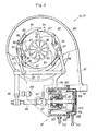
- variable capacity turbocharger 7 is now described in the following with reference to Figure 3. As this turbocharger 7 is conventional as far as its compressor unit 8 is concerned, only its turbine unit 12 is described in the following.
- a turbine casing 80 of the turbocharger 7 is provided with a scroll passage 81 whose cross sectional area gradually diminishes towards its downstream end, and an exhaust outlet 82 opens out from this scroll passage 81 along its tangential direction.
- a turbine wheel 83 which is integrally attached to an end of a turbine shaft coaxial to the compressor shaft.
- the scroll passage 81 Inside the scroll passage 81 are provided four arcuate fixed vanes 84 which are integral with the turbine casing 80 and arranged on a common circle at an equal interval and an equal width. Thus, the scroll passage 81 is separated into an outer passage 85 and an inner passage 86 by these fixed vanes 84.
- Each of the moveable vanes 87 is pivotally supported at one of its circumferential ends so as to be pivotable only into the interior of the aforementioned common circle and define a continual aerofoil in cooperation with the adjacent fixed vane 84.
- the inclination angle of each of the moveable vanes 87 is continually controlled by a moveable vane actuation control unit which will be described hereinafter.
- the moveable vane actuation control unit comprises lever members 89 each projecting integrally from a pivot shaft 88 of each of the moveable vanes 87, a pair of see-saw members 91 each pivotally supported and provided with slots 90 on either end thereof for engagement with two of the lever members 89, a pair of link arms 94 each of which is coupled with the pivot shaft 92 of one of the see-saw members 91 at its one end and to a link rod 93 at its other end, and the actuator 18 serving as a drive source for the moveable vanes 87.
- This actuator 18 is provided with a drive shaft 95 which is adapted to move axially back and forth by fluid pressure and coupled with the link rod 93 via a coupling rod 96.
- the drive shaft 95 and the coupling rod 96 are coupled with each other by a ball joint 97, and the coupling rod 96 and the link rod 93 are coupled with each other by a crevice joint 98 in such a manner that the actuating force from the actuator 18 may be smoothly transmitted to the link arm 94.
- the coupling rod 96 is integrally provided with a stopper 101 which abuts an adjusting bolt 100 threaded with a bracket 99 integrally mounted on the turbine casing 80.
- the actuator 18 comprises a cup-shaped casing 102, and a diaphragm 104 secured to the open end of the casing 102 by crimping a cover 103 thereon, and this diaphragm 103 defines a negative pressure chamber 105 and a positive pressure chamber 106 in the actuator 18.
- a base end of the drive shaft 95 is attached to a central part of the diaphragm 104 via retainers 107 and 108.
- a compression coil spring 109 is interposed between the retainer 107 facing the negative pressure chamber 105 and the bottom wall of the casing 102 to normally urge the diaphragm 104 along with the drive shaft 95 towards the cover 103 or rightward as seen in Figure 3.
- the drive shaft 95 is slidably supported by a central part of the bottom wall of the casing 102.
- the part of the drive shaft 95 projecting out of the bottom wall of the casing 102 is enclosed, in an air-tight fashion, by a soft and frictionless bellows 110 which is made by cutting a cylindrical fluoride resin member in an annular fashion from both inside and outside in an alternating fashion at small interval.
- the interiors of the negative pressure chamber 105 and the bellows 1 10 are communicated with each other by a through hole 111.
- the casing 102 is provided with a negative pressure introduction inlet 112 for communicating the negative pressure chamber 105 with the outside and the cover 103 is provided with a positive pressure introduction inlet 113 for communicating the positive pressure chamber 106 with the outside.
- the link rod 93 is thereby moved leftward as seen in Figure 3, and this in turn causes the link arms 94 to turn in clockwise direction around the pivot shaft 92 with the result that the moveable vanes 87 are turned inwards around the pivot shafts 88 by being actuated by the lever members 89 which are each engaged with the slots 90 on either end of each of the see-saw members 91.
- By thus opening the moveable vanes 87 one can obtain a maximum capacity condition in which the nozzle gaps G N defined between the leading edges of the fixed vanes 84 and the trailing edges of the moveable vanes 87 are maximized (as shown by the double-dot lines in Figure 3).
- the solenoid valve 34 for positive pressure control is controlled and a supercharge pressure P2 is introduced into the positive pressure chamber 106.
- the actuator 18 is thereby actuated in the direction to push out the drive shaft 95, and the see-saw members 91 are turned in clockwise direction by turning the link arms 94 in opposite direction so that the moveable vanes 81 may be turned inward by way of the lever members 89.
- the opening amount of the moveable vanes 87 was controlled primarily by the solenoid valve 34 for positive pressure control in the present embodiment, but it is also possible to use the solenoid valve 35 for negative pressure control in combination.
- the first step 201 it is determined whether an initial mode has been started or, in other words, the engine is being cranked or not. If the engine is being cranked, an elapsed time T DST (for instance 5 seconds) after starting of the engine is set up and the measurement of time after starting of the engine is set ready in the second step 202. Then in the third step 203, a valve close command is issued to the solenoid valve 16, and the engine is operated at low speed valve timing. In the fourth step 204, an elapsed time T DHVT (for instance 0.1 second) after switching over to a high speed valve timing is set and the measurement of delay time after a switch-over to a high speed valve timing is set ready.
- T DST for instance 5 seconds
- T DHVT for instance 0.1 second
- maps T IL and ⁇ IGL corresponding to a low speed valve timing operation is selected as a basic fuel injection amount determining map and ignition timing map which are to be used in a fuel injection control routine, and in the sixth step 206 a revolution limit value N HFC for cutting off fuel supply is set to a value N HFCL which corresponds to low speed valve timing operation.
- T OUT K1 T I + K2
- T I is a basic amount of fuel injection
- K1 is a correction factor
- K2 is a correction term
- K1 accounts for an intake temperature correction factor K TA for increasing fuel supply when the intake temperature T A is low, a cooling water temperature correction factor K TW for increasing fuel supply when the cooling water temperature T W is low, a high load fuel boosting factor K WOT which increases fuel supply in a high speed range determined by the engine rotational sped N E , the intake negative pressure P B and the throttle opening angle ⁇ TH , and a feedback correction factor for correcting the deviation of the air/fuel ratio from a theoretical ratio in an O2 feedback region of a relatively low speed range (for instance 4,000 rpm), while K2 accounts for an acceleration fuel boosting factor which increases fuel supply during acceleration of the engine.
- the basic amount of fuel injection T I is experimentally determined so that intake mixture achieves a target air/fuel ratio which is close to an ideal air/fuel ratio according to the amount of air introduced into the cylinder in each particular operating condition of the engine as determined by the rotational speed of the engine N E and the intake negative pressure P B , and the electronic control circuit 21 stores a T IL map for low speed valve timing operation and a T IH map for high speed valve timing operation, as a T I map.
- the revolution limiter value N HFCL is set to a relatively low value (for instance 7,500 rpm) during low speed valve timing operation and to a relatively high value (for instance 8,100 rpm) during high speed valve timing operation.
- step 201 If it is determined in the first step 201 that the engine is not being cranked or, in other words, the engine is already running, it is then determined in the seventh step 207 whether signals from various sensors are being normally supplied to the electronic control circuit 21 or not, or, in other words, a determination is made whether a fail-safe condition exists or not.
- a predetermined temperature T W1 for instance 60 degrees C
- the system flow advances to the third step 203, and if the cooling water temperature T W is found to be equal to or higher than the predetermined temperature T W1 it is determined in the tenth step 210 whether the vehicle speed V is lower than a certain extremely low speed level V1 (which may contain hysteresis and range from 5 to 8 km/h) or not. If the vehicle speed V is lower than the extremely low speed level V1 the system flow advances to the third step 203, and if the vehicle speed V is equal to or higher than the extremely low speed level V1 it is determined if the vehicle is equipped with a manual transmission system MT or not in the eleventh step 211.
- a certain extremely low speed level V1 which may contain hysteresis and range from 5 to 8 km/h
- a low speed valve timing condition is produced and, at the same time, a corresponding mode of fuel injection control is selected before starting, during cranking, immediately after starting, before engine warm-up, while stopped or while running slowly. This measure is taken in order to prevent occurrence of faulty operation of the coupling switch-over unit 51 due to the viscosity of lubricating oil and occurrence of abnormal combustion.
- the vehicle is not equipped with a manual transmission system MT or it is equipped with an automatic transmission AT, it is determined in the twelfth step 212 if a parking range P or a neutral range N is selected for its shift position or not. If either P or N range is selected, it is determined in the thirteenth step 313 whether a T IH map for high speed valve timing was selected in the previous cycle or not. If not, the system flow returns to the third step 203.
- a comparison is made, in the fourteenth step 214, between a rotational speed lower limit N E1 (which may range between 4,800 and 4,600 rpm including hysteresis), below which the engine output in low speed valve timing condition is always higher than that in high speed valve timing condition, and the current rotational speed N E of the engine. If N E is less than N E1 , it is determined in the fifteenth step 215 if the T IH map for high speed valve timing was used in the previous cycle or not in the same way as in the thirteenth step 213. If not, the system flow advances to the third step 203.
- N E1 which may range between 4,800 and 4,600 rpm including hysteresis
- low speed valve timing is selected either when the vehicle may be stationary even though the rotational speed N E of the engine is high or when, even though the vehicle may be running, its speed is slow or the rotational speed of the engine is low, and a high speed running condition has not been experienced yet.
- a T IL map and the T IH map are searched in the sixteenth step 216 according to the subroutine shown in Figure 4c to find the values of T IL and T IH which correspond to the rotational speed N E and the intake negative pressure P B of the engine at the current stage. Then, in the seventeenth step 217, a T VT value corresponding to the current value of N E is obtained, according to the subroutine given in Figure 4d, from a high load determination value table T VT which is experimentally determined as such according to the amount of fuel injection.
- the T IL value which is to be used in the sixteenth step 216 consists of a value searched from the T IL map when a command to open the solenoid value 16 was not present in the previous cycle, and of a value obtained from the T IL map less a prescribed amount of hysteresis ⁇ T I when a command to open the solenoid value 16 was present in the previous cycle.
- a similar process is executed in regards to the arithmetic process in the seventeenth step 217 for determining a T VT value.
- the T VT value which is to be used in the seventeenth step 217 consists of a value searched from a T VT table when a command to open the solenoid value 16 was not present in the previous cycle, and of a value obtained from the T VT table less a prescribed amount of hysteresis ⁇ T VT when a command to open the solenoid value 16 was present in the previous cycle, whereby a hysteresis is given to the switching property of the amount of fuel injection at the point of valve timing switch over.
- a comparison is made between this T VT value and the amount of fuel injection T OUT in the previous cycle. If the T OUT is found to be less than T VT , a comparison is made in the nineteenth step 219 between a rotational speed upper limit N E2 (which may range between 5,900 and 5,700 rpm including hysteresis) above which the engine output in high speed valve timing condition is always higher than that in low speed valve timing condition, and the current rotational speed N E of the engine.
- N E2 which may range between 5,900 and 5,700 rpm including hysteresis
- N E is less than N E2
- a comparison is made in the twentieth step 220 between the T IL value and the T IH value obtained in the sixteenth step 216, and, if T IL is found to be larger than T IH , a valve close command is supplied to the solenoid valve 16 in the twentyfirst step 221 or, in other words, low speed valve timing is selected.
- the system flow advances to the twentyfirst step 221.
- a valve open command is issued to the solenoid valve 16 or, in other words, a high speed valve timing condition is selected.
- An adjustment is made so as to have a relatively rich mixture in high load range, and a high speed valve timing operation is more desired for increasing the engine output in high load range.
- a point of switching over valve timing is determined in a definite fashion, a hunting may occur in a boundary region and a shock may be produced due to an abrupt change in the torque output at the point of switch over. Therefore, according to the present embodiment, an optimum switch over control action is obtained by carrying out the composite steps of the eighteenth through twentieth steps 218 through 220.
- the system flow advances to the third step 203. Otherwise, the system detects a signal from the oil pressure switch 22 in order to monitor the operating condition of the switch over control valve 17. If it is found that the oil pressure switch 22 is off or that oil pressure is acting upon the coupling switch over unit 51, the remaining time of the delay time T DHVT following the activation of the coupling switch over unit, which was previously set up in the fourth step 204, is determined in the twentyfifth step 225.
- T DHVT 0, in the twentysixth step 226, a preparation for actuation of a delay timer is made following the setting up of a timer for the elapsed time T DLVT (for instance 0.2 seconds) following a switch over to low speed valve timing operation. Then, a fuel injection amount map T IH and an ignition timing ⁇ IGH corresponding to high speed valve timing operation are selected in the twentyseventh step 227, and a revolution limiter value N HFC is changed to a value N HFCH for high speed valve timing in the twentyeighth step 218.
- the system flow advances to the thirtieth step 230 and the low speed valve timing operation is maintained until the oil pressure switch signal O P is turned off.
- the system flow advances to the twentyfifth step 225 and the high speed valve timing operation is maintained until the oil pressure switch signal O P is turned off.
- the time periods T DHVT and T DLVT which were set on the two delay timers in the fourth and the twentysixth steps 204 and 226, respectively, are determined according to the response time required from the time when the solenoid 16 is activated to move the spool valve 70 of the switch over control valve 17 until the time when the oil pressure of the supply oil passage 57 is changed and the switch over action of all the switch over pins is completed for all the cylinders.
- low speed valve timing operation is selected without determining the state of the oil pressure switch signal O P . This measure is taken to prevent the problems which may arise if the signal is kept in its turned-off state due to a failure in the oil pressure switch 22. If the turbocharger end demanded low speed valve timing operation in the twentythird step 223, fuel injection control is immediately switched over so as to adapt itself to low speed valve timing operation. This measure is taken to prevent the occurrence of abnormal combustion due to over-supercharging.
- the solenoid 34 used in the present system for positive pressure control consists of a duty ratio controlled solenoid valve.
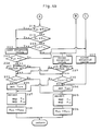
- This supercharge pressure control combines an open loop control which carries out supercharge pressure control according to a basic supercharge pressure control variable (which is referred to as basic duty D M hereinafter), and a feedback control which carries out supercharge pressure control by modifying the basic duty D M according to the deviation of the actual supercharge pressure from a predetermined target supercharge pressure.
- D OUT 100 means a 0% duty ratio condition in which the moveable vanes 87 are displaced to their most outward positions or the cross sectional area of the air passages is minimized.
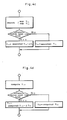
- the feedback delay timer T DFB in the third step 303 is selected according to the subroutine given in Figure 6.
- the main routine shown in Figures 5a through 5d obtains a difference in the values of supercharge pressure over six cycles to accurately determine the behavior of supercharge pressure or the change rate of supercharge pressure because only too small a change is produced in the change rate in supercharge pressure ⁇ P2 for each single TDC signal which renews the main routine given in Figures 5a through 5d.
- a low change rate ⁇ P 2PL and a high change rate ⁇ P 2PH are values determined according to the engine rotational speed N E .
- T DFB1 is set up
- T DFB2 is set up
- ⁇ P2 is larger than ⁇ P 2PL and equal to or less than ⁇ P 2PH
- T DFB2 is set up
- ⁇ P2 is greater than ⁇ P 2PH
- T DFB3 is set up.
- the relationship T DFB1 ⁇ T DFB2 ⁇ T DFB3 holds, and if the supercharge pressure change rate ⁇ P2 is found to be small or if the supercharge pressure P2 changes gradually the delay time T DFB is selected to be small whereas if the supercharge pressure change rate ⁇ P2 is found to be large or if the supercharge pressure P2 changes rapidly the delay time T DFB is selected to be large. In this way, it is made possible to prevent the occurrence of hunting when there is a transition from open loop control to feedback control by selecting a suitable delay time T DFB which is not too large or too small for the change rate in the load.
- step 306 If it is determined in the first step 301 that no start mode is found, it is then determined in the sixth step 306 if a fail-safe condition exists or not. This is carried out by monitoring the results of self-diagnosis by the ECU and the CPU, and input signals from various sensors including the oil pressure switch signal O P , indicating the operating condition of the coupling switch over device 51 for valve timing control, and, in case an abnormal condition should exist, the system flow advances to the second step 302. Otherwise, the system flow advances to the seventh step 307. A comparison is made in the seventh step 307 between an intake temperature T A and a prescribed low intake temperature T AL .
- T A is lower than T AL the system flow advances to the second step 302, but if T A is equal to or higher than T AL the system flow advances to the eighth step 308.
- a comparison is made in the eighth step 308 between a cooling water temperature T W and a prescribed low cooling water temperature T WL . If T W is lower than T WL the system flow advances to the second step 302, but if T W is equal to or higher than T WL the system flow advances to the ninth step 309.
- a comparison is made in the ninth step 309 between an intake temperature T A and a prescribed high intake temperature T AH . If T A is higher than T AH the system flow advances to the second step 302, but if T A is equal to or lower than T AH the system flow advances to the tenth step 310.
- the above described flow may be summarized by that the cross sectional area of the flow passages between the fixed vanes 84 and the moveable vanes 87 is controlled to a maximum value without regard to any other factors in a certain special operating condition where the vehicle is not running, the intake temperature T A or the the cooling water temperature T W is outside a prescribed range or any abnormal condition exists in the control system.
- This measure is taken because in any of such cases it is obvious that the conditions for a stable operation of the engine are not met and introducing a supercharge pressure P2 under such a circumstance will undoubtedly promote instability.
- the basic duty D M is searched from a map as described hereinafter, and a subtraction operation on this D M is carried out in the fifteenth step 315 according to the subroutine shown in Figure 7.
- a discrimination zone is defined in the operating condition of the engine as determined by the rotational speed of the engine N E and intake negative pressure P B as a zone in which a subtraction from the D M value is required, and it is determined whether a subtraction from the D M value should be carried out or not depending on whether the operating condition is located in this discrimination zone or not.
- the process described above produces a low speed valve timing condition and a relatively low supercharge pressure in order to prevent excessive torque output, for instance, in case of an abrupt start up in the first gear.
- the fourteenth step 314 it is determined whether the coupling switch over unit 51 is in the high speed valve timing condition or not. If the high speed valve timing condition is detected, the system flow advances to the seventeenth step 317 where a table P 2HGH adapted for high speed valve timing is selected for determining a high supercharge pressure guard value P 2HG . If not, the system flow advances to the eighteenth step 318 where a table P 2HGL adapted for low speed valve timing is selected for determining a high supercharge pressure guard value P 2HG .
- the high supercharge guard value P 2HG is determined according to the rotational speed of the engine N E so as to obtain a maximum engine output while the durability of the engine is taken into consideration.
- the discrimination whether the current valve timing is adapted for high speed or low speed operation is made according to the presence of a magnetization signal for the solenoid valve 16 in the control unit.
- a comparison is made between the current supercharge pressure P2 and the high supercharge pressure guard value P 2HG obtained from the table selected according to the current valve timing condition. If P2 is found to be higher than P 2HG or a condition of excessive supercharging is detected, a demand is made to the valve timing switch over control program to switch to low speed valve timing in the second step 302 and a control action is taken so as to reduce the supercharge pressure. Conversely, if P2 is found to be lower than P 2HG , the system flow advances to the twentieth step 320 and it is determined again whether the high speed valve timing condition exists or not.
- a basic duty D MH is searched from a map corresponding to high speed valve timing in the twentyfirst step 321, and this value is defined as the D M value in the twentysecond step 322. If no high speed valve timing condition is detected, a basic duty D ML is searched from a map corresponding to low speed valve timing in the twentythird step 323, and this value is defined as the D M value in the twentyfourth step 324.
- the basic duty D M is determined from the rotational speed of the engine N E and the opening angle ⁇ TH of the throttle valve, and is searched from the entries of a table or a map corresponding to the current load condition.
- a throttle opening angle ⁇ TH was used as a parameter for indicating the load condition of the engine, but it may be replaced by intake negative pressure P B or the amount of fuel injection.
- a duty correction factor K MOD a duty correction factor K MOD , an atmospheric pressure duty correction factor K PAD (0.8 to 1.0), and an intake temperature duty correction factor K TAD (0.8 to 1.3) are searched.
- the duty correction factor K MOD is searched from a map of the rotational speed of the engine N E and the intake temperature T A , and is updated by a studying process which is done when an optimum supercharge pressure P2 has fallen within a certain range of deviation.
- the atmospheric pressure duty correction factor K PAD is determined according to the intake pressure P A
- the intake temperature duty correction factor K TAD is determined according to the intake temperature T A .
- the control process is thus adapted to external factors as required.
- a correction factor K DN is searched according to the subroutine given in Figure 8. This subroutine is executed by interrupting the main routine shown in Figures 5a through 5d every time a TDC signal is produced. A timer T DN is reset when the duty D OUT is zero, and the correction factor K DN is set to an initial value K DN0 (for instance 0.5) in response to the first TDC signal after the duty D OUT has ceased to be zero.
- ⁇ K DN (for instance 0.01) is added to K DN every time a TDC signal is received so as to produce a new correction factor K DN each time, and the correction factor K DN is fixed to 1.0 after it has reached the value 1.0.
- the correction factor K DN thus obtained is used in the correction formula for the duty D OUT which is described hereinafter so that the duty D OUT may be forced to zero in case of a special operating condition of the engine where the intake temperature T A is abnormally high or low, the cooling water temperature is abnormally high or low or the supercharge pressure P2 is abnormally high, or, in other words, so that the duty D OUT may be controlled in a stable fashion when the condition in which the gaps between the fixed vanes and the moveable vanes are maximized is removed.
- the correction factor K DN is incremented, for instance, by 0.1 every time a TDC signal is received, to gradually restore the duty D OUT to its normal value so that the occurrence of such an irregular control action may be avoided.
- a comparison is made between the current throttle opening angle ⁇ TH and a predetermined reference throttle opening angle ⁇ THFB .
- This reference throttle opening angle ⁇ THFB corresponds to a medium to high load operating condition of the engine, and is defined so as to permit a judgment of the need for a switch over from open loop control to feedback control.
- ⁇ TH is equal to or less than ⁇ THFB or open loop control is to be continued, after resetting the feedback delay timer T DFB mentioned in conjunction with Figure 6 (the third step) in the twentyeighth step 328, the system flow advances to the twentyninth step 329. If ⁇ TH is determined to be larger than ⁇ THFB in the twentyseventh step 327, it is then determined in the thirtieth step 330 whether the coupling switch over unit 51 is in low speed valve timing condition or not. If a low speed valve timing condition is detected, the system flow advances to the twentyeighth step 328 because open loop control is to be continued. This measure is taken because of a need to depend on open loop control and achieve a higher tracking capability in view of the fact that, in low speed valve timing condition, transient conditions are normal and, furthermore, torque output is relatively small in absolute value.
- a set-up subtraction duty D T and a set-up addition duty D TRB are searched.
- the set-up subtraction duty D T corresponds to the change rate ⁇ P2 of supercharge pressure P2, and is determined by the subroutine given in Figure 9. If ⁇ TH is larger than ⁇ THFB or in case of a medium to high load operating condition in which a transition from open loop control to feedback control takes place, the set-up subtraction duty D T which is set up according to a relationship between the supercharge pressure change rate ⁇ P2 and the rotational speed of the engine N E is selected. If ⁇ TH is equal to or less than ⁇ THFB , no correction of the basic duty D M is made.
- the set-up subtraction duty D T increases in a step-wise manner with an increase in the supercharge pressure change rate ⁇ P2, and can also change, for instance, in three steps, depending on the rotational speed of the engine N E .
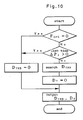
- the set-up addition duty D TRB is determined according to the subroutine given in Figure 10.
- F OPC 1
- F OPC 1
- a set-up addition duty D TRB which is determined by - ⁇ P2 and the rotational speed of the engine N E is selected, and the set-up subtraction duty D T is made zero.
- F OPC 0
- the set-up addition duty D TRB is made zero.
- This set-up addition duty D TRB is also changed depending on the values of the negative supercharge pressure change rate - ⁇ P2 and the rotational speed of the engine N E , and becomes larger as the rotational speed N E of the engine is increased and the negative supercharge pressure change rate - ⁇ P2 is increased.
- reaction from the set-up subtraction duty D T is compensated for, and a stable supercharge pressure control is made possible.
- the duty D OUT is corrected in the thirtyfirst step 331.
- D OUT K MOD x K PAD x K TAD x K DN x (D M + D TRB - D T )
- the output duty D OUT produced in the fifth step 305 reflects the overall operating condition of the engine by taking into account the above mentioned items and other external factors, and allows an optimum supercharge control to be automatically carried out according to the load condition.
- the flag F OPC is set to 1 in the thirtysecond step 332 in order to indicate the existence of an open loop control condition, and the system flow advances to the thirtythird step 333. It is then determined in this step if the D OUT has not exceeded a certain limit value which is determined in advance according to the rotational speed of the engine N E or not, and if it is within the limit value, a duty D OUT is produced in the fifth step 305.
- P2 is found to be larger than P 2ST in the thirtyfifth step 335, a comparison is made in the thirtysixth step 336 between the current supercharge pressure P2 and the feedback control start discrimination supercharge pressure P 2FB .
- P2 is found to be larger than P 2FB , it is determined in the thirtyseventh step 337 whether the time set up on the feedback delay timer T DFB has run out or not, and if so the system flow advances to the thityeighth step 338.
- the system flow advances to the thirtyeighth step 338. If P2 is found to be equal to or less than P 2ST in the thirtyfifth step, the system flow advances to the thirtyninth step 339. If P2 is found to be equal to or less than P 2FB in the thirtysixth step 336, the system flow advances to the twentyeighth step 328. If the time set on the feedback delay timer T DFB has not run out in the thirtyseventh step 337, the system flow advances to the twentyninth step 329.
- the process leading to the fortieth step 340 is intended as a measure to obtain a stable supercharge pressure control in the operating range in which the supercharge pressure P2 rises towards the target supercharge pressure P 2R , and occurrence of overshoots can be avoided irrespective of the supercharge pressure change rate ⁇ P2 by determining the output duty D OUT according to the duty D S which was predetermined according to the rotational speed of the engine N E .
- a comparison is made between the absolute value of the supercharge pressure change rate ⁇ P2 and the feedback control discrimination supercharge pressure difference G ⁇ P2 .
- This G ⁇ P2 is set, for instance, at 30 mmHg, and if the absolute value of the supercharge pressure change rate ⁇ P2 is larger than G ⁇ P2 the system flow advances to the twentyninth step 329. If the absolute value of the supercharge pressure change rate ⁇ P2 is equal to or less than G ⁇ P2 the system flow advances to the fortysecond step 342.
- the system flow returns to the twentyninth step 329 to carry out an open loop control.
- a target supercharge pressure P 2RH for high speed valve timing is searched in the fortyfourth step 344 according to the rotational speed of the engine N E and the intake temperature T A , and this P 2RH is set as a target supercharge pressure P 2R .
- a target supercharge pressure P 2RL for low speed valve timing is searched in the fortyfifth step 345, and this P 2RL is set as a target supercharge pressure P 2R .
- a proportional control term D P K P x (P 2R - P2)
- K P is the proportional control term in a feedback factor, and is determined according to the subroutine given in Figure 11.
- a feedback coefficient K I1 related to an integration control term which is described hereinafter is selected along with K P1 . If the rotational speed of the engine N E is higher than the first switch over rotational speed N FB1 but equal to or lower than a second switch over rotational speed N FB2 , K P2 and K I2 are selected. If the rotational speed of the engine N E is higher than the second switch over rotational speed N FB2 , K P13 and K I3 are selected.
- D I(N) D I(N-1) + K1 + (P 2R - P2)
- the sixtieth step 360 it is determined whether the atmospheric pressure P A is higher than a predetermined reference atmospheric pressure P AM (for instance 650 mmHg) or not.
- a predetermined reference atmospheric pressure P AM for instance 650 mmHg
- the sixtyfirst step 361 it is determined whether the water temperature T W is within a certain predetermined range or not.
- the sixtysecond step 362 it is determined whether the amount of retardation T 2R is non-zero or if a knock condition is being avoided or not.
- the sixtythird step 363 it is determined whether the shift position is other than the first speed range or not. If all these conditions are met the system flow advances to the sixtyfourth step 364 but if any of the conditions is not met the system flow advances to the fiftyseventh step 357.
- K R (K TAD x D M + D IN )/(K TAD x D M )
- K MOD (C MOD x K R )/65536 + (65536 - C MOD ) x K MOD /65536
- the correction factor K MOD is stored in a back-up RAM and the system flow advances to the fiftyseventh step 357.
- the sixtysecond through sixtyseventh steps 362 through 367 are included for the purpose of avoiding any possible ill effects on the operating condition of the engine by prohibiting the storage of the K MOD in case of special operating conditions in storing the results of the studying process during the time the supercharge pressure P2 is controlled in a stable fashion by virtue of the dead zone G P2 .
- a blow-back of intake can be controlled and a relatively high volume efficiency can be obtained in a low speed operating range of an engine if at least either the angular interval of opening the valves or the valve lift is selected to be small.
- the output property of the engine in relation with its rotational speed is dictated by the profiles of the cams. Therefore, two sets of different output properties can be combined into a single engine if the valves actuated by the engine are provided with two interchangeable different cam profiles.
- a supercharged engine increases its output by pressurizing the intake above the atmospheric pressure as it is introduced into the combustion chambers and by thus increasing the effective volume which is displaced by the pistons.
- the upper limit of the supercharge pressure of any particular engine is determined typically according to the design considerations on combustion efficiency and mechanical durability of the particular engine. Therefore, in such an engine as described above which combines a valve operating condition switch over unit and a variable capacity supercharger, it is necessary to carry out supercharge pressure control in two different modes for two different output properties of the engine.
- a set-up addition duty D TRB searched in the twentyninth step 329 is automatically added to the basic duty D M to compensate for such a dip.
Abstract
Description
- The present invention relates to an engine control system for an engine equipped with a variable valve actuating mechanism, such as a variable valve timing system, and a variable capacity supercharger, such as a turbocharger having moveable vanes to vary the cross sectional area of the exhaust gas passage leading to a turbine wheel, and provides an engine control system which permits the advantages of both a variable valve actuating mechanism and a variable capacity supercharger to be fully utilized by harmonious combination of the two variable elements.
- A valve operation switching unit for improving the volume efficiency of the combustion chambers over a wide operation range by changing at least either the angular interval of opening the intake valves and/or exhaust valves for each cylinder or the lift of the valves is proposed for instance in Japanese patent laid open publication No. 63-16111.
- A variable capacity supercharger offering an optimum supercharge pressure over a wide operating range with a high responsiveness by varying the A/R ratio of an exhaust passage leading to a turbine wheel by means of a flap or a plurality of vanes is proposed in Japanese patent laid open publication No. 62-282128.
- According to such a variable capacity supercharger, since a supercharge pressure which is suitable for each operating condition can be arbitrarily and accurately obtained, an even further improvement can be achieved particularly by combining a valve operating condition switching unit and a variable capacity supercharger.
- In a low speed range it is possible to increase the speed of intake flow directed to the combustion chambers by reducing the angular interval of opening the valves and/or the valve lift, but this tends to limit the intake flow rate as the rotational speed of the engine increases. Conversely, by increasing the angular interval of opening the valves and/or the valve lift in high speed range, the volume efficiency of the engine intake improves as the rotational speed of the engine increases. Therefore, if a variable capacity supercharger used in conjunction with a valve operating condition switching unit is controlled in the same way as if it were used for an engine without any such valve operating condition switching unit, it would not be possible to obtain an optimum performance of the engine in all of its operating range.
- In particular, since the change in the movement of the valves during each cycle of engine operation will affect conditions of the intake passages (such as the resonance frequency of the intake passage, the volume efficiency of engine intake, etc.), it is advantageous to adapt the mode of controlling the supercharger to such changes. For instance, in an engine using a valve timing adjusting system which switches over valve timing in step-wise fashion according to the change in the rotational speed of the engine, as the rotational speed of the engine is increased, the torque output reaches a peak value and then gradually diminishes before the valve timing is switched over from a low speed mode to a high speed mode. This decline in the torque output between the point of the torque peak and the point of valve timing switch over may be felt by the operator as a torque dip, and it is desired to remove such a torque dip.
- As an additional consideration, such a complex control action should not involve any undue delay as such a delay will seriously impair the commercial value of the vehicle on which the engine is mounted. However, a high responsiveness of an engine must be accompanied by a sufficient control stability.
- Further, in view of the complexity of the overall control system, it is desired to have a fail safe feature to be incorporated into the system.
- Based upon such and other recognitions, a primary object of the present invention is to provide an engine control system which can achieve a maximum improvement in the performance of an engine which incorporates both a variable capacity supercharger and a variable valve actuating unit.
- A second object of the present invention is to provide such an engine control system which combines a fast response and a stable control action.
- A third object of the present invention is to provide such an engine control system which can eliminate the occurrence of a torque dip which may occur if the valve actuating mechanism is varied in step-wise fashion and the rotational speed is increased close to a point of a step-wise varying action.
- A fourth object of the present invention is to provide such an engine control system which is protected from operating in any undesirable fashion even in case of a system failure.
- These and other objects of the present invention can be accomplished by providing an engine control system, comprising: valve actuating condition varying means for varying a state of a valve actuating mechanism of an engine; capacity varying means for varying a supercharge capacity of a variable capacity supercharger; and control means for controlling a valve actuating condition varying operation of the valve actuating condition varying means and a capacity varying operation of the capacity varying means according to an operating condition including at least a rotational speed of the engine; the control means carrying out the capacity varying operation in dependence upon an operating condition of the valve actuating mechanism.
- Thus, an optimum control of supercharge pressure can be accomplished in response to an operating condition of valves. In particular, if the control means increases the supercharge pressure in case of high speed operation of the engine, the high speed performance of the engine can be improved. Conversely, if supercharge pressure is decreased according to the increase in the torque output of the engine owing to the switching of the valve operating condition, strain on the engine can be reduced in its high speed operating condition.
- According to a preferred embodiment of the present invention, the control means carries out the capacity varying operation of the supercharger by an open loop control process at least when the valve actuating means is adapted for a low speed operating condition of the engine, and by a closed loop control process at least when the valve actuating means is adapted for a high speed operating condition of the engine. Typically, the open loop control process consists of a map control which determines the supercharge capacity according to a rotational speed of the engine and an opening angle of a throttle valve or an intake negative pressure.
- According to the preferred embodiment of the present invention, in order that an undesirable dip in the output property of the engine due to the changes in the intake conditions of the engine due to the activation of the valve actuating condition varying means may be avoided, the control means may change the supercharge pressure of the supercharger at least in a low speed range from a normally controlled level to a boosted level according to a change rate of a level of supercharge pressure, and/or a change rate of a rotational speed of the engine. Normally, the supercharge pressure output of the supercharger should be increased when a decline in the supercharge pressure is detected as the rotational speed of the engine is increased because such decline in the supercharge pressure means a decline in the volume efficiency of the engine intake, and, in order to remove a torque dip resulting therefrom, the supercharge pressure output of the supercharger should be increased to compensate for the reduction in the volume efficiency.
- Now the present invention is described in terms of a specific embodiment by way of example with reference to the appended drawings, in which:
- Figure 1 is an overall structural diagram of the control system for an engine according to the present invention;
- Figure 2 is a structural view of a part surrounding a valve actuating mechanism;
- Figure 3 is a view illustrating the mechanism of the variable capacity turbocharger;
- Figures 4a through 4d are flow charts of the control program which is related to the switch over of valve timing;
- Figures 5a and 5d are flow charts of the control program which is related to the adjustment of supercharge pressure; and
- Figures 6 through 11 are flow charts of the subroutines which are related to the above mentioned programs.
- Figure 1 shows an overall structure of the intake and exhaust system of an engine to which the present invention is applied. In this engine
main body 1, for instance consisting of an in-line four-cylinder engine, anintake manifold 3 leading to theintake port 2 of each cylinder is connected to an intake tube 4, a throttle body 5, an intercooler 6, a compressor unit 8 of a variable capacity supercharger 7, and anair cleaner 9, in that order. Anexhaust manifold 11 leading to theexhaust port 10 of each cylinder is connected to aturbine unit 12 of the variable capacity supercharger 7, and acatalytic converter 13. - A
valve mechanism 14 provided for controlling the intake of mixture and the exhaust of combustion gas into and out of the combustion chamber of each cylinder can change valve timing in a stepwise fashion by controlling hydraulic pressure produced from anoil pump 15 actuated by the enginemain body 1, by way of asolenoid valve 16 and aswitching control valve 17. - The variable capacity supercharger 7 can continually vary a cross sectional area of a passage for exhaust gas leading to its
turbine unit 12 by way of anactuator 18 which is actuated by supercharge pressure P₂ immediately downstream of the compressor unit 8 or intake negative pressure immediately downstream of the throttle valve 5 to vary the supercharging capacity of its compressor unit 8. This turbocharger 7, along with the intercooler 6, is cooled by cooling water which is circulated by awater pump 19 actuated by the enginemain body 1 through a cooling water system including aradiator 20, which is separate from the cooling water system for the enginemain body 1. - The
engine 1 is equipped with anelectronic control circuit 21 for controlling the amount of fuel injection, valve timing and supercharge pressure for theengine 1. - The
electronic control circuit 21 receives an oil pressure signal OP from anoil pressure switch 22 of a normally closed type provided in theswitching control valve 17, an O₂ signal from anoxygen concentration sensor 23 provided in theexhaust manifold 11, a rotational speed signal NE from an enginerotational speed sensor 24, a water temperature signal TW from a coolingwater temperature sensor 25 provided in the water packet of the enginemain body 1, a parking/neutral signal PN indicating the shift position of theautomatic transmission system 26 to be either in a parking or neutral range, an intake temperature signal TA and an intake pressure signal PB from anintake temperature sensor 27 and anintake pressure sensor 28, respectively, provided in a part of the intake passage 4a downstream of the throttle body 5, a throttle valve opening angle signal ϑTH from a throttleopening angle sensor 29, a supercharge pressure signal P₂ from asupercharge pressure sensor 30 provided in a part of theintake passage 4b downstream of the compressor unit 8, an atmospheric pressure signal PA from anatmospheric pressure sensor 31 provided in a part of the intake passage 4c extending between theair cleaner 9 and the compressor unit 8 of the turbocharger 7, and a vehicle speed signal V from avehicle speed sensor 32. Output signals from thiselectronic control circuit 21 control the operations of solenoid valves for switching over valve timing,fuel injection valves 33 for injecting fuel into theintake ports 2, andsolenoid valves actuator 18 for varying the supercharger capacity. - The
valve actuating mechanism 14 is now described in the following with reference to Figure 2. - The engine to which the present invention is applied consists of a so-called DOHC engine in which intake valves and exhaust valves are actuated by separate camshafts, and each cylinder is equipped with two intake valves and two exhaust valves. Since the intake valves and the exhaust valves have substantially the same structure, only the part of the
valve actutating mechanism 14 related to the intake valve mechanism is described in the following. - For each cylinder, three
rocker arms rocker arm shaft 40, which is secured to a cylinder head, adjacent to each other and so as to be rotatable in mutually independent manner. Acamshaft 45 is rotatably supported bycam journals 44 formed in the cylinder head above therocker arms - The
camshaft 45 is provided, for each cylinder, with a pair oflow speed cams high speed cam 47 having a relatively large open valve angular interval and a relatively large valve lift. A pair ofoil supply tubes camshaft 45 to lubricate thecamshaft 45 and the sliding surfaces between the cams and the rocker arms. The free ends of the first andsecond rocker arms low speed cams intake valves third rocker arm 43 disposed between the first andsecond rocker arms high speed cam 47 is engaged, at its lower end, with a lost motion spring not shown in the drawing so as to be normally urged upwards. - The first through
third rocker arms 41 through 43 which are disposed one next to the other are internally provided with a coupling switch overunit 51 which consists of a guide bore passed through the rocker arms and switching pins slidably received therein. - The
first rocker arm 41 is provided with a first guide bore 52 having an open end facing thethird rocker arm 43 and a closed bottom end and extending in parallel with therocker arm shaft 40. The first guide bore 52 slidably receives a first switchingpin 53 therein. The bottom end of thefirst guide bore 52 defines anoil pressure chamber 54 which is communicated with anoil supply passage 57 defined in the hollowrocker arm shaft 40 via anoil passage 55 defined in thefirst rocker arm 41 and an oil supply opening 56 opening on an outer periphery of therocker arm shaft 40. - The
third rocker arm 43 is provided with asecond guide bore 58 which extends in parallel with therocker arm shaft 40 and aligns with the first guide bore 52 in a conformal and coaxial manner at its rest position in which its cam slipper engages with a base circle of thehigh speed cam 47, and asecond switching pin 59 is received therein with its one end abutting thefirst switching pin 53. - The
second rocker arm 42 is likewise provided with a third guide bore 60 having a closed bottom end, and receives astopper pin 61 therein with its one end abutting the other end of thesecond switching pin 59. - The
stopper pin 61 has astem portion 63 which is received in aguide sleeve 62 fitted into the bottom end of the third guide bore 60, and is normally elastically urged towards thethird rocker arm 43 by areturn spring 64. - By displacing the first and
second switching pins oil pressure chamber 54 and the biasing force of thereturn spring 64, one can selectively obtain either a state in which therocker arms 41 through 43 can move independently as shown in Figure 2 and another state in which therocker arms 41 through 43 are integrally coupled with one another by the switchingpins intake valves - The downstream end of the
oil supply passage 57 internally provided in therocker shaft 40 is connected to one of the aforementioned oil passages or, more specifically, the high speedoil supply tube 49. This high speedoil supply tube 49 is provided with anozzle 65 for spraying lubricating oil onto a position corresponding to thehigh speed cam 47. - The other oil supply tube or the low speed
oil supply tube 48 is connected to alubrication oil passage 66 branched off from an oil gallery. This low speedoil supply tube 48 is provided withnozzles 67 for spraying lubricating oil onto positions corresponding to thecams cam journals 44 viaoil passages 68. - The
switching control valve 17, mounted on the cylinder head, is actuated by oil pressure which is supplied from thesolenoid valve 16 controlled by the aforementioned control signal,and is internally provided with aspool valve 70 which is normally urged towards its closed position by areturn spring 69. - When this
spool valve 70 is at its upper closed position (as shown in Figure 2), aninflow port 72 leading to thelubrication oil passage 66 is communicated, via an oil filter 71, with anoutflow port 73 leading to theoil passage 57 in therocker arm shaft 40 solely through anorifice 74. At the same time, theoutflow port 73 is communicated with adrain port 75 opening into an upper space of the cylinder head, and the oil pressure in theoil supply passage 57 thereby drops. Therefore, no oil pressure is supplied to theoil supply passage 57, and thepins oil pressure chamber 54 under the spring force of thereturn spring 64 so that the rocker arms are independently actuated by the associated cams and undergo independent angular displacements. In this case, the oil supplied by theoil pump 15 from anoil pan 76 to the oil gallery is supplied to the low speed lubricatingoil supply tube 48 via the lubricatingoil passage 66, and lubricates the sliding surfaces between the cams and the rocker arm as well as thecam journals 44. - When the
spool valve 70 is switched over to its lower open position, theinflow port 72 communicates with theoutflow port 73 via an annular groove 77 of thespool valve 70 and theoutflow port 73 is disconnected from thedrain port 75 so that oil under pressure is supplied from thelubrication oil passage 66 to theoil supply passage 57. As pressurized oil is thereby supplied to theoil pressure chamber 54 of thefirst rocker arm 41, the first and second switching pins 53 and 59 are forced into the second guide bore 58 and the third guide bore 60, respectively, against the biasing force of thereturn spring 64, and therocker arms 41 through 43 are integrally coupled with one another. The pressurized oil which is supplied to theoil supply passage 57 to actuate the coupling switch overunit 51 is then supplied to the high speed lubricationoil supply tube 49 via the downstream end of theoil supply passage 57 to lubricate the sliding surface between thehigh speed cam 47 and thethird rocker arm 43. - The
spool valve 70 is switched over to its open position, against the biasing force of thereturn spring 69, by a pilot pressure which is applied to the upper end of thespool valve 70 from apilot oil passage 78 branched off from theinflow port 72. The normally closedsolenoid valve 16 is interposed in thispilot oil passage 78 and the solenoid of thissolenoid valve 16 is controlled by an output signal from theelectronic control circuit 21 in such a manner that thespool valve 70 is brought to its open position by opening of thesolenoid valve 16 to thereby achieve a high speed valve timing and thespool valve 70 is brought to its closed position by closing of thesolenoid valve 16 to thereby achieve a low speed valve timing. - The switching action of the
spool valve 70 is monitored by theoil pressure switch 22 provided in the housing of the switchingcontrol valve 17 to be turned on and off depending on the detection of a low pressure and a high pressure, respectively, in the oil pressure of theoutflow port 73. - The variable capacity turbocharger 7 is now described in the following with reference to Figure 3. As this turbocharger 7 is conventional as far as its compressor unit 8 is concerned, only its
turbine unit 12 is described in the following. - A
turbine casing 80 of the turbocharger 7 is provided with ascroll passage 81 whose cross sectional area gradually diminishes towards its downstream end, and anexhaust outlet 82 opens out from thisscroll passage 81 along its tangential direction. In a central part of thescroll passage 81 is located aturbine wheel 83 which is integrally attached to an end of a turbine shaft coaxial to the compressor shaft. - Inside the
scroll passage 81 are provided four arcuate fixedvanes 84 which are integral with theturbine casing 80 and arranged on a common circle at an equal interval and an equal width. Thus, thescroll passage 81 is separated into anouter passage 85 and aninner passage 86 by these fixedvanes 84. - Four
moveable vanes 87, each having a substantially same curvature as the fixedvanes 84, are disposed between the fixedvanes 84 on the same common circle as the fixedvanes 84. Each of themoveable vanes 87 is pivotally supported at one of its circumferential ends so as to be pivotable only into the interior of the aforementioned common circle and define a continual aerofoil in cooperation with the adjacent fixedvane 84. The inclination angle of each of themoveable vanes 87 is continually controlled by a moveable vane actuation control unit which will be described hereinafter. - The moveable vane actuation control unit comprises
lever members 89 each projecting integrally from apivot shaft 88 of each of themoveable vanes 87, a pair of see-saw members 91 each pivotally supported and provided withslots 90 on either end thereof for engagement with two of thelever members 89, a pair oflink arms 94 each of which is coupled with thepivot shaft 92 of one of the see-saw members 91 at its one end and to alink rod 93 at its other end, and theactuator 18 serving as a drive source for themoveable vanes 87. Thisactuator 18 is provided with adrive shaft 95 which is adapted to move axially back and forth by fluid pressure and coupled with thelink rod 93 via acoupling rod 96. - In the above described link mechanism, the
drive shaft 95 and thecoupling rod 96 are coupled with each other by a ball joint 97, and thecoupling rod 96 and thelink rod 93 are coupled with each other by a crevice joint 98 in such a manner that the actuating force from theactuator 18 may be smoothly transmitted to thelink arm 94. Also, in order to define fully open positions of themoveable vanes 87 by restricting the stroke of thedrive shaft 95, thecoupling rod 96 is integrally provided with astopper 101 which abuts an adjustingbolt 100 threaded with abracket 99 integrally mounted on theturbine casing 80. - The
actuator 18 comprises a cup-shapedcasing 102, and adiaphragm 104 secured to the open end of thecasing 102 by crimping acover 103 thereon, and thisdiaphragm 103 defines anegative pressure chamber 105 and apositive pressure chamber 106 in theactuator 18. - A base end of the
drive shaft 95 is attached to a central part of thediaphragm 104 viaretainers compression coil spring 109 is interposed between theretainer 107 facing thenegative pressure chamber 105 and the bottom wall of thecasing 102 to normally urge thediaphragm 104 along with thedrive shaft 95 towards thecover 103 or rightward as seen in Figure 3. - The
drive shaft 95 is slidably supported by a central part of the bottom wall of thecasing 102. The part of thedrive shaft 95 projecting out of the bottom wall of thecasing 102 is enclosed, in an air-tight fashion, by a soft andfrictionless bellows 110 which is made by cutting a cylindrical fluoride resin member in an annular fashion from both inside and outside in an alternating fashion at small interval. The interiors of thenegative pressure chamber 105 and thebellows 1 10 are communicated with each other by a throughhole 111. - The
casing 102 is provided with a negativepressure introduction inlet 112 for communicating thenegative pressure chamber 105 with the outside and thecover 103 is provided with a positivepressure introduction inlet 113 for communicating thepositive pressure chamber 106 with the outside. - In this
actuator 18, when a positive pressure is introduced into thepositive pressure chamber 106 from the positivepressure introduction inlet 113, thediaphragm 104 is pushed leftward as seen in Figure 3 against the biasing force of thecompression coil spring 109, and thedrive shaft 95 is driven leftward. When a negative pressure is introduced into thenegative pressure chamber 105 from the negativepressure introduction inlet 112, thedrive shaft 95 is likewise driven leftward by thediaphragm 104. In other words, in a low opening angle range of the throttle valve where the intake negative pressure PB is high, theactuator 18 is actuated so as to push out thedrive shaft 95. Thelink rod 93 is thereby moved leftward as seen in Figure 3, and this in turn causes thelink arms 94 to turn in clockwise direction around thepivot shaft 92 with the result that themoveable vanes 87 are turned inwards around thepivot shafts 88 by being actuated by thelever members 89 which are each engaged with theslots 90 on either end of each of the see-saw members 91. By thus opening themoveable vanes 87, one can obtain a maximum capacity condition in which the nozzle gaps GN defined between the leading edges of the fixedvanes 84 and the trailing edges of themoveable vanes 87 are maximized (as shown by the double-dot lines in Figure 3). - When the supply of a negative pressure PB to the
negative pressure chamber 105 is discontinued by controlling theaforementioned solenoid 35 for controlling negative pressure, the negative pressure in thenegative pressure chamber 105 is reduced and thedrive shaft 95 is pulled in by the spring force of thecoil spring 109. As a result, thelink rod 93 is moved rightward as seen in Figure 3, and the see-saw members 91 are turned by thelink arms 94 in counter-clockwise direction so that themoveable vanes 87 are moved outward around thepivot shafts 88 by way of thelever members 89 each engaged with theslots 90 on either end of each of the see-saw member 91 (as shown by the solid and broken lines in figure 3). By thus closing themoveable vanes 87, one can obtain a minimum capacity condition in which the nozzle gaps GN defined between the leading edges of the fixedvanes 84 and the trailing edges of themoveable vanes 87 are minimized. Therefore, the exhaust gas flow is narrowed and accelerated to the maximum extent and drives theturbine wheel 83 as a circular flow flowing through the innercircumferential passage 86 so as to maximize the effect of supercharging in low speed range of the engine. - As the rotational speed of the engine is increased and a sufficient supercharge effect is obtained, the
solenoid valve 34 for positive pressure control is controlled and a supercharge pressure P₂ is introduced into thepositive pressure chamber 106. Theactuator 18 is thereby actuated in the direction to push out thedrive shaft 95, and the see-saw members 91 are turned in clockwise direction by turning thelink arms 94 in opposite direction so that themoveable vanes 81 may be turned inward by way of thelever members 89. By thus expanding the nozzle gaps GN, no acceleration is effected on exhaust gas and the exhaust gas encounters little flow resistance whereby the engine is subjected to less back pressure. - The opening amount of the
moveable vanes 87 was controlled primarily by thesolenoid valve 34 for positive pressure control in the present embodiment, but it is also possible to use thesolenoid valve 35 for negative pressure control in combination. - A control program incorporated in the
electronic circuit 21 to control thesolenoid valve 16 for valve timing switch-over is now described in the following with reference to Figures 4a and 4b. - In the
first step 201 it is determined whether an initial mode has been started or, in other words, the engine is being cranked or not. If the engine is being cranked, an elapsed time TDST (for instance 5 seconds) after starting of the engine is set up and the measurement of time after starting of the engine is set ready in thesecond step 202. Then in thethird step 203, a valve close command is issued to thesolenoid valve 16, and the engine is operated at low speed valve timing. In thefourth step 204, an elapsed time TDHVT (for instance 0.1 second) after switching over to a high speed valve timing is set and the measurement of delay time after a switch-over to a high speed valve timing is set ready. In thefifth step 205, maps TIL and ϑIGL corresponding to a low speed valve timing operation is selected as a basic fuel injection amount determining map and ignition timing map which are to be used in a fuel injection control routine, and in the sixth step 206 a revolution limit value NHFC for cutting off fuel supply is set to a value NHFCL which corresponds to low speed valve timing operation. - Now, the amount of fuel injection TOUT is given by the following formula:
TOUT = K1 TI + K2
where TI is a basic amount of fuel injection, K1 is a correction factor, and K2 is a correction term. - K1 accounts for an intake temperature correction factor KTA for increasing fuel supply when the intake temperature TA is low, a cooling water temperature correction factor KTW for increasing fuel supply when the cooling water temperature TW is low, a high load fuel boosting factor KWOT which increases fuel supply in a high speed range determined by the engine rotational sped NE, the intake negative pressure PB and the throttle opening angle ϑTH, and a feedback correction factor for correcting the deviation of the air/fuel ratio from a theoretical ratio in an O₂ feedback region of a relatively low speed range (for instance 4,000 rpm), while K2 accounts for an acceleration fuel boosting factor which increases fuel supply during acceleration of the engine.
- The basic amount of fuel injection TI is experimentally determined so that intake mixture achieves a target air/fuel ratio which is close to an ideal air/fuel ratio according to the amount of air introduced into the cylinder in each particular operating condition of the engine as determined by the rotational speed of the engine NE and the intake negative pressure PB, and the
electronic control circuit 21 stores a TIL map for low speed valve timing operation and a TIH map for high speed valve timing operation, as a TI map. - The shorter the angular interval of opening the valves, the greater the valve acceleration becomes during the opening phase of the valves. At the same time, as the valve acceleration increases, the rotational speed NE of the engine at which the valves start jumping becomes lower. Therefore, the permissible maximum rotational speed of the engine differs depending on whether a high speed valve timing condition or a low speed valve timing condition is being selected as they have different intervals of opening the valves. According to the present embodiment, the revolution limiter value NHFCL is set to a relatively low value (for instance 7,500 rpm) during low speed valve timing operation and to a relatively high value (for instance 8,100 rpm) during high speed valve timing operation.
- If it is determined in the
first step 201 that the engine is not being cranked or, in other words, the engine is already running, it is then determined in theseventh step 207 whether signals from various sensors are being normally supplied to theelectronic control circuit 21 or not, or, in other words, a determination is made whether a fail-safe condition exists or not. - If it is judged that no fail-safe situation exists or, in other words, a normal condition exists, the time remaining from the time interval TDST after starting the engine, which was set up in the
second step 202, is evaluated in theeighth step 208. If the remaining time is not zero, the system flow advances to thethird step 203. If there is no remaining time, the system flow advances to theninth step 209 where it is determined whether the cooling water temperature TW is less than a predetermined temperature TW1 (forinstance 60 degrees C) or not, or, in other words, whether the engine has been warmed up or not. If the cooling water temperature TW is found to be less than the predetermined temperature TW1, the system flow advances to thethird step 203, and if the cooling water temperature TW is found to be equal to or higher than the predetermined temperature TW1 it is determined in thetenth step 210 whether the vehicle speed V is lower than a certain extremely low speed level V₁ (which may contain hysteresis and range from 5 to 8 km/h) or not. If the vehicle speed V is lower than the extremely low speed level V₁ the system flow advances to thethird step 203, and if the vehicle speed V is equal to or higher than the extremely low speed level V₁ it is determined if the vehicle is equipped with a manual transmission system MT or not in theeleventh step 211. - Thus, a low speed valve timing condition is produced and, at the same time, a corresponding mode of fuel injection control is selected before starting, during cranking, immediately after starting, before engine warm-up, while stopped or while running slowly. This measure is taken in order to prevent occurrence of faulty operation of the coupling switch-over
unit 51 due to the viscosity of lubricating oil and occurrence of abnormal combustion. - If it is determined in the
eleventh step 211 that the vehicle is not equipped with a manual transmission system MT or it is equipped with an automatic transmission AT, it is determined in thetwelfth step 212 if a parking range P or a neutral range N is selected for its shift position or not. If either P or N range is selected, it is determined in thethirteenth step 313 whether a T IH map for high speed valve timing was selected in the previous cycle or not. If not, the system flow returns to thethird step 203. If the vehicle is equipped with a manual transmission system, a comparison is made, in thefourteenth step 214, between a rotational speed lower limit NE1 (which may range between 4,800 and 4,600 rpm including hysteresis), below which the engine output in low speed valve timing condition is always higher than that in high speed valve timing condition, and the current rotational speed NE of the engine. If NE is less than NE1, it is determined in thefifteenth step 215 if the TIH map for high speed valve timing was used in the previous cycle or not in the same way as in thethirteenth step 213. If not, the system flow advances to thethird step 203. - It can be seen in the preceding steps that low speed valve timing is selected either when the vehicle may be stationary even though the rotational speed NE of the engine is high or when, even though the vehicle may be running, its speed is slow or the rotational speed of the engine is low, and a high speed running condition has not been experienced yet.
- On the other hand, if it is found in the
fourteenth step 214 that NE is equal to or higher than NE1, a TIL map and the TIH map are searched in thesixteenth step 216 according to the subroutine shown in Figure 4c to find the values of TIL and TIH which correspond to the rotational speed NE and the intake negative pressure PB of the engine at the current stage. Then, in theseventeenth step 217, a TVT value corresponding to the current value of NE is obtained, according to the subroutine given in Figure 4d, from a high load determination value table TVT which is experimentally determined as such according to the amount of fuel injection. - As for values from the TIL and TIH maps, the TIL value which is to be used in the
sixteenth step 216 consists of a value searched from the TIL map when a command to open thesolenoid value 16 was not present in the previous cycle, and of a value obtained from the TIL map less a prescribed amount of hysteresis ΔTI when a command to open thesolenoid value 16 was present in the previous cycle. A similar process is executed in regards to the arithmetic process in theseventeenth step 217 for determining a TVT value. The TVT value which is to be used in theseventeenth step 217 consists of a value searched from a TVT table when a command to open thesolenoid value 16 was not present in the previous cycle, and of a value obtained from the TVT table less a prescribed amount of hysteresis ΔTVT when a command to open thesolenoid value 16 was present in the previous cycle, whereby a hysteresis is given to the switching property of the amount of fuel injection at the point of valve timing switch over. - In the subsequent
eighteenth step 218, a comparison is made between this TVT value and the amount of fuel injection TOUT in the previous cycle. If the TOUT is found to be less than TVT, a comparison is made in thenineteenth step 219 between a rotational speed upper limit NE2 (which may range between 5,900 and 5,700 rpm including hysteresis) above which the engine output in high speed valve timing condition is always higher than that in low speed valve timing condition, and the current rotational speed NE of the engine. If NE is less than NE2, a comparison is made in thetwentieth step 220 between the TIL value and the TIH value obtained in thesixteenth step 216, and, if TIL is found to be larger than TIH, a valve close command is supplied to thesolenoid valve 16 in thetwentyfirst step 221 or, in other words, low speed valve timing is selected. - If it was found in the
thirteenth step 213 or in thefifteenth step 215 that the T IH map was selected in the previous cycle or a low load and low rotational speed condition is produced after experiencing a high speed running condition, the system flow advances to thetwentyfirst step 221. - On the other hand, if it was found in the
eighteenth step 218 that TOUT is equal to or larger than TVT, if it was found in thenineteenth step 219 that NE is equal to or larger than NE2, or if it was found in thetwentieth step 220 that TIL is equal to or less than TIH, a valve open command is issued to thesolenoid valve 16 or, in other words, a high speed valve timing condition is selected. Thus, it can be seen that a point of switch over between high speed valve timing and low speed valve timing is determined from the rotational speed of the engine and the demanded amount of fuel injection. - An adjustment is made so as to have a relatively rich mixture in high load range, and a high speed valve timing operation is more desired for increasing the engine output in high load range. However, if the point of switching over valve timing is determined in a definite fashion, a hunting may occur in a boundary region and a shock may be produced due to an abrupt change in the torque output at the point of switch over. Therefore, according to the present embodiment, an optimum switch over control action is obtained by carrying out the composite steps of the eighteenth through
twentieth steps 218 through 220. - Following selection of high speed valve timing operation, it is determined in the twentythird step if zero value is placed in a flag FLVT to indicate that low speed valve timing operation is not selected in the turbocharger control routine which will be described hereinafter. If it is determined that the turbocharger end presupposes low speed valve timing operation, the system flow advances to the
third step 203. Otherwise, the system detects a signal from theoil pressure switch 22 in order to monitor the operating condition of the switch overcontrol valve 17. If it is found that theoil pressure switch 22 is off or that oil pressure is acting upon the coupling switch overunit 51, the remaining time of the delay time TDHVT following the activation of the coupling switch over unit, which was previously set up in thefourth step 204, is determined in thetwentyfifth step 225. If TDHVT = 0, in thetwentysixth step 226, a preparation for actuation of a delay timer is made following the setting up of a timer for the elapsed time TDLVT (for instance 0.2 seconds) following a switch over to low speed valve timing operation. Then, a fuel injection amount map TIH and an ignition timing ϑIGH corresponding to high speed valve timing operation are selected in the
twentyseventh step 227, and a revolution limiter value NHFC is changed to a value NHFCH for high speed valve timing in thetwentyeighth step 218. - Following the issuing of a valve close command to the
solenoid valve 16 in thetwentyfirst step 221, presence of an oil pressure switch signal OP is detected in thetwentyninth step 229. If theoil pressure switch 22 is turned on or no oil pressure is being applied to the coupling switch overunit 51, the time remaining from TDLVT which was set in thetwentysixth step 226 is read out, and, if TDLVT=0 the system flow returns to thefourth step 204. - If the oil pressure switch signal OP is not turned off in the
twentyfourth step 224 even though a switch over from low speed valve timing operation to a high speed valve timing operation is effected, the system flow advances to thethirtieth step 230 and the low speed valve timing operation is maintained until the oil pressure switch signal OP is turned off. Conversely, if the oil pressure switch signal OP is not turned on in thetwentyninth step 229 even though a switch over from high speed valve timing operation to low speed valve timing operation is effected, the system flow advances to thetwentyfifth step 225 and the high speed valve timing operation is maintained until the oil pressure switch signal OP is turned off. - The time periods TDHVT and TDLVT which were set on the two delay timers in the fourth and the
twentysixth steps solenoid 16 is activated to move thespool valve 70 of the switch overcontrol valve 17 until the time when the oil pressure of thesupply oil passage 57 is changed and the switch over action of all the switch over pins is completed for all the cylinders. Even when the beginning of a switch over action is detected from the oil pressure switch signal OP, it is supposed that the change of valve timing for all the cylinders is not completed until TDLVT=0 in case of a switch over from high speed to low speed or TDHVT=0 in case of a switch over from low speed to high speed, and the engine is continued to be controlled according to the mode of fuel injection amount control preceding the command for a valve timing switch over. - If the TIH map was not selected in the
thirteenth step 213 or thefifteenth step 215 in the previous cycle or if the vehicle has just started moving or is accelerating, low speed valve timing operation is selected without determining the state of the oil pressure switch signal OP. This measure is taken to prevent the problems which may arise if the signal is kept in its turned-off state due to a failure in theoil pressure switch 22. If the turbocharger end demanded low speed valve timing operation in thetwentythird step 223, fuel injection control is immediately switched over so as to adapt itself to low speed valve timing operation. This measure is taken to prevent the occurrence of abnormal combustion due to over-supercharging. - The control program for the
solenoid 34 in varying the supercharge capacity of the turbocharger 7 or supercharge pressure is now described in the following with reference to Figures 5a through 5d. It should be noted that thesolenoid 34 used in the present system for positive pressure control consists of a duty ratio controlled solenoid valve. This supercharge pressure control combines an open loop control which carries out supercharge pressure control according to a basic supercharge pressure control variable (which is referred to as basic duty DM hereinafter), and a feedback control which carries out supercharge pressure control by modifying the basic duty DM according to the deviation of the actual supercharge pressure from a predetermined target supercharge pressure. - It is determined in the
first step 301 whether a start mode has been produced or not, or, in other words, whether the engine is being cranked or not. If a start mode has been detected, it is indicated by a flag FLVT=1 that valve timing is going to be fixed to low speed valve timing in thesecond step 302. Then, after resetting a timer TDFB for delaying the onset of a feedback control in thethird step 303, the duty DOUT for thesolenoid 34 is set to zero in thefourth step 304 before it is outputted in thefifth step 305. Here, it should be noted that the duty ratio of the solenoid of thesolenoid valve 34 diminishes as the duty DOUT in the main routine becomes larger, and that DOUT=0 means a 100% duty ratio condition in which themoveable vanes 87 are displaced to their most inward positions or in which thesolenoid valve 34 is fully opened to maximize the cross sectional area of the air passages between the fixedvanes 84 and themoveable vanes 87. On the other hand, DOUT=100 means a 0% duty ratio condition in which themoveable vanes 87 are displaced to their most outward positions or the cross sectional area of the air passages is minimized. - The feedback delay timer TDFB in the
third step 303 is selected according to the subroutine given in Figure 6. One of three timers TDFB1, TDFB2 and TDFB3 is selected according to the change rate ΔP₂ of the supercharge pressure P₂ which is given as a difference between the current supercharge pressure P2N and the supercharge pressure P2N-6 of six cycles ago (ΔP₂ = P2N - P2N-6). In other words, the main routine shown in Figures 5a through 5d obtains a difference in the values of supercharge pressure over six cycles to accurately determine the behavior of supercharge pressure or the change rate of supercharge pressure because only too small a change is produced in the change rate in supercharge pressure ΔP₂ for each single TDC signal which renews the main routine given in Figures 5a through 5d. A low change rate ΔP2PL and a high change rate ΔP2PH are values determined according to the engine rotational speed NE. If ΔP₂ is equal to or less than ΔP2PL the TDFB1 is set up, if ΔP₂ is larger than ΔP2PL and equal to or less than ΔP2PH the TDFB2 is set up, and if ΔP₂ is greater than ΔP2PH the TDFB3 is set up. Further, the relationship TDFB1 < TDFB2 < TDFB3 holds, and if the supercharge pressure change rate ΔP₂ is found to be small or if the supercharge pressure P₂ changes gradually the delay time TDFB is selected to be small whereas if the supercharge pressure change rate ΔP₂ is found to be large or if the supercharge pressure P₂ changes rapidly the delay time TDFB is selected to be large. In this way, it is made possible to prevent the occurrence of hunting when there is a transition from open loop control to feedback control by selecting a suitable delay time TDFB which is not too large or too small for the change rate in the load. - If it is determined in the
first step 301 that no start mode is found, it is then determined in thesixth step 306 if a fail-safe condition exists or not. This is carried out by monitoring the results of self-diagnosis by the ECU and the CPU, and input signals from various sensors including the oil pressure switch signal OP, indicating the operating condition of the coupling switch overdevice 51 for valve timing control, and, in case an abnormal condition should exist, the system flow advances to thesecond step 302. Otherwise, the system flow advances to theseventh step 307. A comparison is made in theseventh step 307 between an intake temperature TA and a prescribed low intake temperature TAL. If TA is lower than TAL the system flow advances to thesecond step 302, but if TA is equal to or higher than TAL the system flow advances to theeighth step 308. A comparison is made in theeighth step 308 between a cooling water temperature TW and a prescribed low cooling water temperature TWL. If TW is lower than TWL the system flow advances to thesecond step 302, but if TW is equal to or higher than TWL the system flow advances to theninth step 309. A comparison is made in theninth step 309 between an intake temperature TA and a prescribed high intake temperature TAH. If TA is higher than TAH the system flow advances to thesecond step 302, but if TA is equal to or lower than TAH the system flow advances to thetenth step 310. A comparison is made in thetenth step 310 between the cooling water temperature TW and a prescribed high cooling water temperature TWH. If TW is higher than TWH the system flow advances to thesecond step 302, but if TW is equal to or lower than TWH the system flow advances to theeleventh step 311. The current shift position of the transmission system is detected in theeleventh step 311, and the system flow advances to thesecond step 302 if a parking range P or a neutral range N is selected and otherwise advances to thetwelfth step 312. - The above described flow may be summarized by that the cross sectional area of the flow passages between the fixed
vanes 84 and themoveable vanes 87 is controlled to a maximum value without regard to any other factors in a certain special operating condition where the vehicle is not running, the intake temperature TA or the the cooling water temperature TW is outside a prescribed range or any abnormal condition exists in the control system. This measure is taken because in any of such cases it is obvious that the conditions for a stable operation of the engine are not met and introducing a supercharge pressure P₂ under such a circumstance will undoubtedly promote instability. At the same time, the valve timing switch over control program is executed in such a manner that valve timing control is fixed to low speed valve timing control by setting the flag FLVT=1 and the coupling switch overunit 51 is fixed to a condition for low speed valve timing. - If it is determined in the preceding steps that the engine is in a stable operating condition and the vehicle is running, it is determined in the
twelfth step 312 if the shift position is in a first speed range or not. If not, the system flow advances to thefourteenth step 314 after setting the flag FLVT=0 to indicate that an override condition for low speed valve timing operation is released in thethirteenth step 313. If the shift position is found to be in a first speed range, the system flow advances to thefourteenth step 314 after a subtraction process is carried out on the basic duty DM serving as a basic supercharge control variable in thefifteenth step 315 and, at the same time, the flag FLVT=1 is set in thesixteenth step 316 to indicate the existence of an override condition for low speed valve timing operation. - The basic duty DM is searched from a map as described hereinafter, and a subtraction operation on this DM is carried out in the
fifteenth step 315 according to the subroutine shown in Figure 7. In other words, a discrimination zone is defined in the operating condition of the engine as determined by the rotational speed of the engine NE and intake negative pressure PB as a zone in which a subtraction from the DM value is required, and it is determined whether a subtraction from the DM value should be carried out or not depending on whether the operating condition is located in this discrimination zone or not. The output torque of the engine can be determined from the rotational speed of the engine NE and the intake negative pressure PB, but the boundary of the discrimination zone represents a permissible torque of the gear shafts in the first speed range, and this measure is taken in order to ensure that the force acting upon the gear shafts may not be excessive. If the operating condition is located outside of the discrimination zone or the permissible torque is not exceeded, the system flow advances to the next step without modifying the searched DM value. However, if the operating condition falls within the discrimination zone or the permissible torque has been exceeded, it is determined whether the flag indicating the condition of feedback control is zero or FOPC=0 or not. If the condition of open loop control exists, a subtraction is carried out as given in the following to somewhat reduce the duty DOUT for the solenoid valve 34:
DM = searched DM - DF
where DF is a predetermined subtraction constant. If the condition of feedback control exists, a subtraction is carried out as given in the following to somewhat reduce the target supercharge pressure P2R:
P2R = searched P2R - ΔP2R
where P2R is a target supercharge pressure under the feedback control condition as determined by the rotational speed of the engine NE and the intake temperature TA and ΔP2R is a predetermined subtraction constant. - The process described above produces a low speed valve timing condition and a relatively low supercharge pressure in order to prevent excessive torque output, for instance, in case of an abrupt start up in the first gear.
- In the
fourteenth step 314 it is determined whether the coupling switch overunit 51 is in the high speed valve timing condition or not. If the high speed valve timing condition is detected, the system flow advances to theseventeenth step 317 where a table P2HGH adapted for high speed valve timing is selected for determining a high supercharge pressure guard value P2HG. If not, the system flow advances to theeighteenth step 318 where a table P2HGL adapted for low speed valve timing is selected for determining a high supercharge pressure guard value P2HG. The high supercharge guard value P2HG is determined according to the rotational speed of the engine NE so as to obtain a maximum engine output while the durability of the engine is taken into consideration. - The discrimination whether the current valve timing is adapted for high speed or low speed operation is made according to the presence of a magnetization signal for the
solenoid valve 16 in the control unit. - In the
nineteenth step 319, a comparison is made between the current supercharge pressure P₂ and the high supercharge pressure guard value P2HG obtained from the table selected according to the current valve timing condition. If P₂ is found to be higher than P2HG or a condition of excessive supercharging is detected, a demand is made to the valve timing switch over control program to switch to low speed valve timing in thesecond step 302 and a control action is taken so as to reduce the supercharge pressure. Conversely, if P₂ is found to be lower than P2HG, the system flow advances to thetwentieth step 320 and it is determined again whether the high speed valve timing condition exists or not. - If the presence of the high speed valve timing condition is detected in the
twentieth step 320, a basic duty DMH is searched from a map corresponding to high speed valve timing in thetwentyfirst step 321, and this value is defined as the DM value in thetwentysecond step 322. If no high speed valve timing condition is detected, a basic duty DML is searched from a map corresponding to low speed valve timing in thetwentythird step 323, and this value is defined as the DM value in thetwentyfourth step 324. The basic duty DM is determined from the rotational speed of the engine NE and the opening angle ϑTH of the throttle valve, and is searched from the entries of a table or a map corresponding to the current load condition. - It is thus possible to adapt the engine to various operating conditions including deceleration and transient operation conditions by preparing separate maps defined by engine rotational speed NE and throttle opening angle ϑTH for high speed valve timing and low speed valve timing and changing the mode of supercharge pressure control according to the condition of valve timing. Here, a throttle opening angle ϑTH was used as a parameter for indicating the load condition of the engine, but it may be replaced by intake negative pressure PB or the amount of fuel injection.
- In the
twentyfifth step 325, a duty correction factor KMOD, an atmospheric pressure duty correction factor KPAD (0.8 to 1.0), and an intake temperature duty correction factor KTAD (0.8 to 1.3) are searched. The duty correction factor KMOD is searched from a map of the rotational speed of the engine NE and the intake temperature TA, and is updated by a studying process which is done when an optimum supercharge pressure P₂ has fallen within a certain range of deviation. The atmospheric pressure duty correction factor KPAD is determined according to the intake pressure PA, and the intake temperature duty correction factor KTAD is determined according to the intake temperature TA. The control process is thus adapted to external factors as required. - In the
twentysixth step 326, a correction factor KDN is searched according to the subroutine given in Figure 8. This subroutine is executed by interrupting the main routine shown in Figures 5a through 5d every time a TDC signal is produced. A timer TDN is reset when the duty DOUT is zero, and the correction factor KDN is set to an initial value KDN0 (for instance 0.5) in response to the first TDC signal after the duty DOUT has ceased to be zero. After a certain time interval TDN0 (for instance 5 seconds) set on the timer TDN has run out, ΔKDN (for instance 0.01) is added to KDN every time a TDC signal is received so as to produce a new correction factor KDN each time, and the correction factor KDN is fixed to 1.0 after it has reached the value 1.0. - The correction factor KDN thus obtained is used in the correction formula for the duty DOUT which is described hereinafter so that the duty DOUT may be forced to zero in case of a special operating condition of the engine where the intake temperature TA is abnormally high or low, the cooling water temperature is abnormally high or low or the supercharge pressure P₂ is abnormally high, or, in other words, so that the duty DOUT may be controlled in a stable fashion when the condition in which the gaps between the fixed vanes and the moveable vanes are maximized is removed. When the operating condition has returned from a special condition in which DOUT=0 to a normal operation condition, if the duty immediately returned to a normal value, an irregular control action might take place on the boundary between the special operating condition and the normal operating condition. Therefore, upon elapsing of, for instance, 5 seconds after the normal operating condition is restored, the correction factor KDN is incremented, for instance, by 0.1 every time a TDC signal is received, to gradually restore the duty DOUT to its normal value so that the occurrence of such an irregular control action may be avoided.
- Then, in the
twentyseventh step 327, a comparison is made between the current throttle opening angle ϑTH and a predetermined reference throttle opening angle ϑTHFB. This reference throttle opening angle ϑTHFB corresponds to a medium to high load operating condition of the engine, and is defined so as to permit a judgment of the need for a switch over from open loop control to feedback control. By using a throttle opening angle ϑTH as a judgment parameter, it becomes possible to make an accurate judgment on the need for supercharging under each particular operating condition. If ϑTH is equal to or less than ϑTHFB or open loop control is to be continued, after resetting the feedback delay timer TDFB mentioned in conjunction with Figure 6 (the third step) in thetwentyeighth step 328, the system flow advances to thetwentyninth step 329. If ϑTH is determined to be larger than ϑTHFB in thetwentyseventh step 327, it is then determined in thethirtieth step 330 whether the coupling switch overunit 51 is in low speed valve timing condition or not. If a low speed valve timing condition is detected, the system flow advances to thetwentyeighth step 328 because open loop control is to be continued. This measure is taken because of a need to depend on open loop control and achieve a higher tracking capability in view of the fact that, in low speed valve timing condition, transient conditions are normal and, furthermore, torque output is relatively small in absolute value. - In the
twentyninth step 329, a set-up subtraction duty DT and a set-up addition duty DTRB are searched. The set-up subtraction duty DT corresponds to the change rate ΔP₂ of supercharge pressure P₂, and is determined by the subroutine given in Figure 9. If ϑTHis larger than ϑTHFB or in case of a medium to high load operating condition in which a transition from open loop control to feedback control takes place, the set-up subtraction duty DT which is set up according to a relationship between the supercharge pressure change rate ΔP₂ and the rotational speed of the engine NE is selected. If ϑTH is equal to or less than ϑTHFB, no correction of the basic duty DM is made. - The set-up subtraction duty DT increases in a step-wise manner with an increase in the supercharge pressure change rate ΔP₂, and can also change, for instance, in three steps, depending on the rotational speed of the engine NE. Thus, the higher the rotational speed of the engine is, the larger the subtraction value becomes. This process is started immediately before the actual supercharge pressure reaches a target supercharge pressure P2R so that the transition from open loop control to feedback control may be carried out in a smooth fashion.
- The set-up addition duty DTRB is determined according to the subroutine given in Figure 10. When an open loop control condition exists (FOPC=1) and the supercharge pressure change rate ΔP₂ is negative, a set-up addition duty DTRB which is determined by -ΔP₂ and the rotational speed of the engine NE is selected, and the set-up subtraction duty DT is made zero. When a feedback control condition exists (FOPC=0) or the supercharge pressure change rate ΔP₂ is positive, the set-up addition duty DTRB is made zero. This set-up addition duty DTRB is also changed depending on the values of the negative supercharge pressure change rate - ΔP₂ and the rotational speed of the engine NE, and becomes larger as the rotational speed NE of the engine is increased and the negative supercharge pressure change rate - ΔP₂ is increased. Thus, reaction from the set-up subtraction duty DT is compensated for, and a stable supercharge pressure control is made possible.
- After the various correction factors KMOD, KPAD, KTAD and KDN, the set-up subtraction duty DT and the set-up addition duty DTRB are determined, the duty DOUT is corrected in the
thirtyfirst step 331.
DOUT = KMOD x KPAD x KTAD x KDN x (DM + DTRB - DT) - Therefore, the output duty DOUT produced in the
fifth step 305 reflects the overall operating condition of the engine by taking into account the above mentioned items and other external factors, and allows an optimum supercharge control to be automatically carried out according to the load condition. - Then, the flag FOPC is set to 1 in the
thirtysecond step 332 in order to indicate the existence of an open loop control condition, and the system flow advances to thethirtythird step 333. It is then determined in this step if the DOUT has not exceeded a certain limit value which is determined in advance according to the rotational speed of the engine NE or not, and if it is within the limit value, a duty DOUT is produced in thefifth step 305. - Meanwhile, if it is determined in the
thirtieth step 330 that no low speed valve timing condition exists, the system flow advances to the thirtyfourth step 334 (Figure 5c). - The flag of the previous cycle is determined in the
thirtyfourth step 334. If FOPC=1 or an open loop control condition existed in the previous cycle, a comparison is made in thethirtyfifth step 335 between the current supercharge pressure P₂ and the duty control start discrimination supercharge pressure P2ST. This duty control start discrimination supercharge pressure P2ST is given from the following equation:
P2ST = P2R - ΔP2ST
where ΔP2ST is a subtraction value which is determined in advance according to the supercharge pressure change rate ΔP₂ and the rotational speed of the engine NE, and becomes larger as the engine rotational speed increases and as the supercharge pressure change rate ΔP₂ becomes larger. - If P₂ is found to be larger than P2ST in the
thirtyfifth step 335, a comparison is made in thethirtysixth step 336 between the current supercharge pressure P₂ and the feedback control start discrimination supercharge pressure P2FB. This feedback control start discrimination supercharge pressure P2FB is given from the following equation:
P2FB = P2R - ΔP2FB
where ΔP2FB is also a subtraction value which is determined in advance according to the supercharge pressure change rate ΔP₂ and the rotational speed of the engine NE. - If P₂ is found to be larger than P2FB, it is determined in the
thirtyseventh step 337 whether the time set up on the feedback delay timer TDFB has run out or not, and if so the system flow advances to thethityeighth step 338. - If the flag FOPC=0 in the
thirtyfourth step 334 or a feedback control condition existed in the previous cycle, the system flow advances to thethirtyeighth step 338. If P₂ is found to be equal to or less than P2ST in the thirtyfifth step, the system flow advances to thethirtyninth step 339. If P₂ is found to be equal to or less than P2FB in thethirtysixth step 336, the system flow advances to thetwentyeighth step 328. If the time set on the feedback delay timer TDFB has not run out in thethirtyseventh step 337, the system flow advances to thetwentyninth step 329. - A set-up duty DS is searched in the
thirtyninth step 339, as an auxiliary basic supercharge pressure control variable which is predetermined according to the rotational speed of the engine NE, and the duty DOUT is computed in thefortieth step 340 according to the following formula:
DOUT = DS x KTAD x KPAD - Then, after resetting the feedback delay timer TDFB in the
fortyfirst step 341, the system flow advances to thethirtythird step 333. - The process leading to the
fortieth step 340 is intended as a measure to obtain a stable supercharge pressure control in the operating range in which the supercharge pressure P₂ rises towards the target supercharge pressure P2R, and occurrence of overshoots can be avoided irrespective of the supercharge pressure change rate ΔP₂ by determining the output duty DOUT according to the duty DS which was predetermined according to the rotational speed of the engine NE. - In the
thirtyeighth step 338, a comparison is made between the absolute value of the supercharge pressure change rate ΔP₂ and the feedback control discrimination supercharge pressure difference GΔP2. This GΔP2 is set, for instance, at 30 mmHg, and if the absolute value of the supercharge pressure change rate ΔP₂ is larger than GΔP2 the system flow advances to thetwentyninth step 329. If the absolute value of the supercharge pressure change rate ΔP₂ is equal to or less than GΔP2 the system flow advances to thefortysecond step 342. Thus, if the absolute value of the supercharge pressure change rate ΔP₂ is larger than GΔP₂ or, in other words, if the supercharge rate ΔP₂ is sharper than a prescribed limit when a feedback control is about to be started, as hunting could occur, the system flow returns to thetwentyninth step 329 to carry out an open loop control. - It is determined in the
fortysecond step 342 whether the coupling switch overunit 51 is adapted for high speed valve timing or not. If a high speed valve timing condition is detected, a target supercharge pressure P2RH for high speed valve timing is searched in thefortyfourth step 344 according to the rotational speed of the engine NE and the intake temperature TA, and this P2RH is set as a target supercharge pressure P2R. If absence of a high speed vale timing condition is detected, a target supercharge pressure P2RL for low speed valve timing is searched in thefortyfifth step 345, and this P2RL is set as a target supercharge pressure P2R. This measure is taken in view of the fact that the intake volume efficiency changes according to valve timing or the amount of valve opening in order to maximize the engine output in a most efficient manner by changing the setting of the target supercharge pressure P2R according to the selected valve timing. - It is then determined in the
fortyseventh step 347 if the first speed range is selected on the automatic transmission system or not. If the first speed range is detected and if it is found that the operating condition falls within a prescribed discrimination zone in thefortyeighth step 348 according to the subroutine shown in Figure 7, the system flow advances to thefortyninth step 349 after carrying out the following subtraction:
P2R = searched P2R - ΔP2R
where ΔP2R is a subtraction value which is set up in response to the first range condition of the automatic transmission system. If the shift position is found to be other than the first speed range in the fortyseventh step, the system flow advances to thefortyninth step 349 without carrying out any subtraction from the target supercharge pressure P2R. - A prescribed supercharge atmospheric pressure correction factor KPAP2 is searched in the
fortyninth step 349 according to the atmospheric pressure PA, and correction of the target supercharge pressure P2R is made by carrying out the following arithmetic operation in the fiftieth step 350:
corrected P2R = searched P2R x KPAP2 x KRTB
where KRTB is a correction factor to account for a knock condition of the engine. - It is determined in the
fiftyfirst step 351 whether the absolute value of the difference between the target supercharge pressure P2R and the current supercharge pressure P₂ is equal to or larger than a predetermined value GP2 which is given as a dead zone in the feedback control and may be selected at 20 mmHg, for instance. If the absolute value of the difference between the target supercharge pressure P2R and the current supercharge pressure P₂ is equal to or larger than the predetermined value GP2, the system flow advances to thefiftysecond step 352 where a proportional control term DP is computed according to the following formula:
DP = KP x (P2R - P₂) - In the above formula, KP is the proportional control term in a feedback factor, and is determined according to the subroutine given in Figure 11. In Figure 11, if the rotational speed of the engine NE is equal to or lower than a first switch over rotational speed NFB1, a feedback coefficient KI1 related to an integration control term which is described hereinafter is selected along with KP1. If the rotational speed of the engine NE is higher than the first switch over rotational speed NFB1 but equal to or lower than a second switch over rotational speed NFB2, KP2 and KI2 are selected. If the rotational speed of the engine NE is higher than the second switch over rotational speed NFB2, KP13 and KI3 are selected.
- In the
fiftythird step 353, a correction coefficient KMOD associated with the current rotational speed of the engine NE and intake temperature TA is searched, and it is determined in thefiftyfourth step 354 if the flag FOPC was equal to 1 in the previous cycle or not, or, in other words, if the current feedback condition was produced for the first time or not. If FOPC=1 or if an open loop control condition existed in the previous cycle, the integration control term DI(N-1) of the previous cycle is computed in thefiftyfifth step 355 according to the following formula:
DI(N-1) = KTAD x KPAD x DM x (KMOD - 1) - Upon completion of this computing process, the system flow advances to the
fiftysixth step 356. However, if FOPC=0 or if no open loop control condition was detected in thefiftyfourth step 354, after circumventing thefiftyfifth step 355, the system flow advances to thefiftysixth step 356 and a current integration control term DIN is computed according to the following formula:
DI(N) = DI(N-1) + K₁ + (P2R - P₂) - Thereafter, in the
fiftyseventh step 357, the duty DOUT is computed or the following arithmetic operation is carried out:
DOUT = KTAD x KPAD x KDM x DM + DP + DIN
Then, after setting the flag FOPC=0 in thefiftyeighth step 358, the system flow advances to thefiftythird step 333. - On the other hand, if the absolute value of P₂ error is determined to be less than GP2, the proportional control term DP=0 and the integration control term DIN=DI(N-1) are set up in the
fiftyninth step 359. In thesixtieth step 360, it is determined whether the atmospheric pressure PA is higher than a predetermined reference atmospheric pressure PAM (for instance 650 mmHg) or not. In thesixtyfirst step 361, it is determined whether the water temperature TW is within a certain predetermined range or not. In thesixtysecond step 362, it is determined whether the amount of retardation T2R is non-zero or if a knock condition is being avoided or not. In thesixtythird step 363, it is determined whether the shift position is other than the first speed range or not. If all these conditions are met the system flow advances to thesixtyfourth step 364 but if any of the conditions is not met the system flow advances to thefiftyseventh step 357. - A coefficient KR for a studying process related to the duty correction factor KMOD is computed in the
sixtyfourth step 364 according to the following formula:
KR = (KTAD x DM + DIN)/(KTAD x DM) - Then, in the
sixtyfifth step 365, to search for the correction factor KMOD and carry out a studying process, the following arithmetic operation is carried out:
KMOD = (CMOD x KR)/65536 + (65536 - CMOD) x KMOD/65536
After checking the limit of this KMOD in thesixtysixth step 366, the correction factor KMOD is stored in a back-up RAM and the system flow advances to thefiftyseventh step 357. - The sixtysecond through
sixtyseventh steps 362 through 367 are included for the purpose of avoiding any possible ill effects on the operating condition of the engine by prohibiting the storage of the KMOD in case of special operating conditions in storing the results of the studying process during the time the supercharge pressure P₂ is controlled in a stable fashion by virtue of the dead zone GP2. - It is thus advantageous to rely on open loop control which offers a fast response in low to medium speed range where operating conditions tend to change rapidly and transient conditions are frequently produced. On the other hand, in high speed range, since a fast response is not so crucial, a stable and accurate feedback control may be used without any ill effects.
- A blow-back of intake can be controlled and a relatively high volume efficiency can be obtained in a low speed operating range of an engine if at least either the angular interval of opening the valves or the valve lift is selected to be small. On the other hand, it is desirable to increase at least one of the valve opening angular interval and the valve lift in a high speed operating range of an engine in view of obtaining a required amount of intake. In other words, the output property of the engine in relation with its rotational speed is dictated by the profiles of the cams. Therefore, two sets of different output properties can be combined into a single engine if the valves actuated by the engine are provided with two interchangeable different cam profiles.
- Meanwhile, as opposed to a natural aspiration engine in which intake is drawn into its combustion chambers solely by the negative pressure produced by the reciprocating movement of its pistons, a supercharged engine increases its output by pressurizing the intake above the atmospheric pressure as it is introduced into the combustion chambers and by thus increasing the effective volume which is displaced by the pistons. The upper limit of the supercharge pressure of any particular engine is determined typically according to the design considerations on combustion efficiency and mechanical durability of the particular engine. Therefore, in such an engine as described above which combines a valve operating condition switch over unit and a variable capacity supercharger, it is necessary to carry out supercharge pressure control in two different modes for two different output properties of the engine.
- Therefore, according to the present invention, by preparing a plurality of sets of maps for searching a basic supercharge pressure control variable DM for carrying out duty control and a target supercharge pressure set up value P2R for feedback control depending on the differences in the operating conditions of the intake valves and the exhaust valves, and by switching over these maps in response to the switch over signals for the operation of the valves, an optimum control performance adapted to each particular operating condition can be achieved.
- In particular, if supercharge pressure is required to be boosted in a high speed range, supercharge efficiency is even further improved due to the increase in the amount of valve opening. If the supercharge pressure may be reduced in a high speed range by virtue of the gain in the output due to the change in valve timing, the compression ratio can be reduced while a sufficient output can be obtained.
- Thus, according to the present invention, since supercharge pressure control can be carried out in response to the switch over in valve timing, engine output can be increased over an even broader operating range. Particularly since the supercharge pressure in a high speed range can be reduced without reducing engine output, the knock limit can be raised through lower combustion temperature and the burden on the engine can be reduced with the result that the improvements in both engine output and engine durability can be achieved at the same time.
- To eliminate the dip in the engine output resulting from the change in the conditions of the intake passage due to the existence of regions near a point of step-wise switch over of the valve actuating mechanism, upon detection of a negative supercharge pressure change rate ΔP₂ or any dip in engine output torque, a set-up addition duty DTRB searched in the
twentyninth step 329 is automatically added to the basic duty DM to compensate for such a dip. - In the
steps - 1. When the engine is being cranked, the rotational speed of the engine is inevitably unstable, and adjusting valve timing or a supercharge capacity under such a circumstance will lead to an unstable operation of the engine. Therefore, it is preferable to fix valve timing to low speed condition which reduces the possibility of intake blow-back and a supercharge capacity to a large capacity level which presents less flow resistance to intake.
- 2. Should any abnormal condition arise in the control system, there is a good chance that the valve timing switch over and the capacity varying action for the supercharger is not carried out as desired. In such a case, low speed condition and a large capacity condition should be selected for the valve actuating mechanism and the supercharger as a fail-safe measure.
- 3. When the intake or the cooling water is excessively cold, the density of the intake becomes high and the resulting tendency for over-supercharging may be detrimental to the durability of the engine. Also, a high viscosity of lubricating oil may prevent satisfactory switch over action of the valve actuating mechanism. Therefore, in this case also, low speed condition and a large capacity condition are desirable for the valve actuating mechanism and the supercharger, respectively.
- 4. When the intake or the cooling water is excessively high, the magnetic property of the solenoids of the solenoid valves may be adversely affected by the high temperature, and the control accuracy may be doubtful. At the same time, a high temperature tends to cause detonation and other irregular combustions and lower the knock limit. Therefore, in this case also, low speed condition and a large capacity condition are desirable in view of the durability of the engine.
- 5. When supercharging is carried out and/or a high speed valve timing condition is selected in the first speed range of the transmission system, an excessive large torque may be transmitted through the transmission system of the vehicle. Therefore, again, low speed condition and a large capacity condition are desirable in view of the durability of the engine.
Claims (10)
valve actuating condition varying means for varying a state of a valve actuating mechanism of an engine;
capacity varying means for varying a supercharge capacity of a variable capacity supercharger; and
control means for controlling a valve actuating condition varying operation of said valve actuating condition varying means and a capacity varying operation of said capacity varying means according to an operating condition including at least a rotational speed of said engine;
said control means carrying out said capacity varying operation in dependence upon an operating condition of said valve actuating mechanism.
Applications Claiming Priority (2)
| Application Number | Priority Date | Filing Date | Title |
|---|---|---|---|
| JP63328551A JP2662277B2 (en) | 1988-12-26 | 1988-12-26 | Engine control device |
| JP328551/88 | 1988-12-26 |
Publications (3)
| Publication Number | Publication Date |
|---|---|
| EP0376703A2 true EP0376703A2 (en) | 1990-07-04 |
| EP0376703A3 EP0376703A3 (en) | 1990-10-10 |
| EP0376703B1 EP0376703B1 (en) | 1993-12-22 |
Family
ID=18211543
Family Applications (1)
| Application Number | Title | Priority Date | Filing Date |
|---|---|---|---|
| EP89313622A Expired - Lifetime EP0376703B1 (en) | 1988-12-26 | 1989-12-27 | Engine control system |
Country Status (3)
| Country | Link |
|---|---|
| EP (1) | EP0376703B1 (en) |
| JP (1) | JP2662277B2 (en) |
| DE (1) | DE68911664T2 (en) |
Cited By (10)
| Publication number | Priority date | Publication date | Assignee | Title |
|---|---|---|---|---|
| EP0786589A1 (en) * | 1996-01-26 | 1997-07-30 | C.R.F. Società Consortile per Azioni | Method and unit for controlling the supercharge pressure of a turbodiesel engine with a variable-geometry turbine |
| FR2771137A1 (en) * | 1997-11-14 | 1999-05-21 | Daimler Benz Ag | Control procedure for variable geometry turbine used to supercharge internal combustion engine |
| GB2355497A (en) * | 1999-10-18 | 2001-04-25 | Ford Global Tech Inc | Controlling a supercharged i.c. engine with variable valve timing |
| US6467442B2 (en) | 1999-10-18 | 2002-10-22 | Ford Global Technologies, Inc. | Direct injection variable valve timing engine control system and method |
| EP1300569A1 (en) * | 2001-10-05 | 2003-04-09 | Peugeot Citroen Automobiles SA | Method and device for controlling an internal combustion engine |
| US6560527B1 (en) | 1999-10-18 | 2003-05-06 | Ford Global Technologies, Inc. | Speed control method |
| US6634328B2 (en) | 1999-10-18 | 2003-10-21 | Ford Global Technologies, Llc | Engine method |
| US7367316B2 (en) | 1999-10-18 | 2008-05-06 | Ford Global Technologies, Llc | Vehicle control system |
| US7398762B2 (en) | 2001-12-18 | 2008-07-15 | Ford Global Technologies, Llc | Vehicle control system |
| CN101449042B (en) * | 2006-05-23 | 2012-03-28 | 丰田自动车株式会社 | Vehicle, and its control method |
Families Citing this family (5)
| Publication number | Priority date | Publication date | Assignee | Title |
|---|---|---|---|---|
| DE10231143B4 (en) | 2002-07-10 | 2004-08-12 | Siemens Ag | Method for controlling the valve lift of discretely adjustable intake valves of a multi-cylinder internal combustion engine |
| DE102004031231B4 (en) * | 2004-06-29 | 2007-11-08 | Audi Ag | Method for operating an internal combustion engine with an adjusting device for changing the valve opening during operation |
| DE102004031227B4 (en) * | 2004-06-29 | 2008-08-07 | Audi Ag | Method for carrying out adjusting operations with adjustable camshafts of internal combustion engines |
| DE102004031295B4 (en) * | 2004-06-29 | 2008-03-13 | Audi Ag | Method for carrying out adjusting operations for valves in internal combustion engines with multiple combustion chambers and internal combustion engine for carrying out the procedure |
| DE102005006491B4 (en) * | 2005-02-12 | 2008-09-04 | Audi Ag | Method and device for controlling cam profiles of a camshaft of a multi-cylinder internal combustion engine |
Citations (5)
| Publication number | Priority date | Publication date | Assignee | Title |
|---|---|---|---|---|
| JPS60145420A (en) * | 1984-01-07 | 1985-07-31 | Nissan Motor Co Ltd | Intake mechanism for internal-combustion engine with supercharger |
| GB2160260A (en) * | 1984-04-25 | 1985-12-18 | Nissan Motor | Supercharging pressure control for turbocharged i c engines |
| US4660382A (en) * | 1984-02-29 | 1987-04-28 | Nissan Motor Co., Ltd. | Device for controlling the supercharging pressure of a turbocharger |
| US4698972A (en) * | 1984-12-07 | 1987-10-13 | Nissan Motor Co., Ltd. | Method of and apparatus for controlling supercharge pressure for a turbocharger |
| JPH01113519A (en) * | 1987-10-27 | 1989-05-02 | Hino Motors Ltd | Turbo-supercharger |
Family Cites Families (2)
| Publication number | Priority date | Publication date | Assignee | Title |
|---|---|---|---|---|
| JPS60116823A (en) * | 1983-11-29 | 1985-06-24 | Nissan Motor Co Ltd | Actuating device of suction valve of internal-combustion engine with supercharger |
| JPH065017B2 (en) * | 1985-04-30 | 1994-01-19 | マツダ株式会社 | Valve timing controller for engine with supercharger |
-
1988
- 1988-12-26 JP JP63328551A patent/JP2662277B2/en not_active Expired - Fee Related
-
1989
- 1989-12-27 EP EP89313622A patent/EP0376703B1/en not_active Expired - Lifetime
- 1989-12-27 DE DE89313622T patent/DE68911664T2/en not_active Expired - Lifetime
Patent Citations (5)
| Publication number | Priority date | Publication date | Assignee | Title |
|---|---|---|---|---|
| JPS60145420A (en) * | 1984-01-07 | 1985-07-31 | Nissan Motor Co Ltd | Intake mechanism for internal-combustion engine with supercharger |
| US4660382A (en) * | 1984-02-29 | 1987-04-28 | Nissan Motor Co., Ltd. | Device for controlling the supercharging pressure of a turbocharger |
| GB2160260A (en) * | 1984-04-25 | 1985-12-18 | Nissan Motor | Supercharging pressure control for turbocharged i c engines |
| US4698972A (en) * | 1984-12-07 | 1987-10-13 | Nissan Motor Co., Ltd. | Method of and apparatus for controlling supercharge pressure for a turbocharger |
| JPH01113519A (en) * | 1987-10-27 | 1989-05-02 | Hino Motors Ltd | Turbo-supercharger |
Non-Patent Citations (2)
| Title |
|---|
| PATENT ABSTRACTS OF JAPAN, vol. 009, no. 311 (M-436), 7th December 1985; & JP-A-60 145 420 (NISSAN JIDOSHA K.K.) 31-07-1985 * |
| PATENT ABSTRACTS OF JAPAN, vol. 013, no. 335 (M-856), 27th July 1989; & JP-A-01 113 519 (HINO MOTORS LTD) 02-05-1989 * |
Cited By (30)
| Publication number | Priority date | Publication date | Assignee | Title |
|---|---|---|---|---|
| EP0786589A1 (en) * | 1996-01-26 | 1997-07-30 | C.R.F. Società Consortile per Azioni | Method and unit for controlling the supercharge pressure of a turbodiesel engine with a variable-geometry turbine |
| US5867986A (en) * | 1996-01-26 | 1999-02-09 | C.R.F. Societa Consortile Per Azioni | Method and unit for controlling the supercharge pressure of a turbodiesel engine with a variable-geometry turbine |
| FR2771137A1 (en) * | 1997-11-14 | 1999-05-21 | Daimler Benz Ag | Control procedure for variable geometry turbine used to supercharge internal combustion engine |
| US8671909B2 (en) | 1999-07-14 | 2014-03-18 | Ford Global Technologies, Llc | Vehicle control system |
| US8371264B2 (en) | 1999-07-14 | 2013-02-12 | Ford Global Technologies, Llc | Vehicle control system |
| US7290527B2 (en) | 1999-07-14 | 2007-11-06 | Ford Global Technologies Llc | Vehicle control system |
| US7117847B2 (en) | 1999-10-18 | 2006-10-10 | Ford Global Technologies, Llc | Vehicle control system |
| US6945225B2 (en) | 1999-10-18 | 2005-09-20 | Ford Global Technologies, Llc | Speed control method |
| GB2355497A (en) * | 1999-10-18 | 2001-04-25 | Ford Global Tech Inc | Controlling a supercharged i.c. engine with variable valve timing |
| US6560527B1 (en) | 1999-10-18 | 2003-05-06 | Ford Global Technologies, Inc. | Speed control method |
| US6626147B2 (en) | 1999-10-18 | 2003-09-30 | Ford Global Technologies, Llc | Control method for a vehicle having an engine |
| US6634328B2 (en) | 1999-10-18 | 2003-10-21 | Ford Global Technologies, Llc | Engine method |
| US6651620B2 (en) | 1999-10-18 | 2003-11-25 | Ford Global Technologies, Llc | Engine method |
| US6705284B2 (en) | 1999-10-18 | 2004-03-16 | Ford Global Technologies, Llc | Engine method |
| US6712041B1 (en) | 1999-10-18 | 2004-03-30 | Ford Global Technologies, Inc. | Engine method |
| GB2355497B (en) * | 1999-10-18 | 2004-04-28 | Ford Global Tech Inc | Control method for a vehicle having an engine |
| US6945227B2 (en) | 1999-10-18 | 2005-09-20 | Ford Global Technologies, Llc | Direct injection variable valve timing engine control system and method |
| US6467442B2 (en) | 1999-10-18 | 2002-10-22 | Ford Global Technologies, Inc. | Direct injection variable valve timing engine control system and method |
| US6962139B2 (en) | 1999-10-18 | 2005-11-08 | Ford Global Technologies, Llc | Speed control method |
| US6978764B1 (en) | 1999-10-18 | 2005-12-27 | Ford Global Technologies, Inc. | Control method for a vehicle having an engine |
| US7000588B2 (en) | 1999-10-18 | 2006-02-21 | Ford Global Technologies, Llc | Engine method |
| US6490643B2 (en) | 1999-10-18 | 2002-12-03 | Ford Global Technologies, Inc. | Control method for a vehicle having an engine |
| US6470869B1 (en) | 1999-10-18 | 2002-10-29 | Ford Global Technologies, Inc. | Direct injection variable valve timing engine control system and method |
| US7367316B2 (en) | 1999-10-18 | 2008-05-06 | Ford Global Technologies, Llc | Vehicle control system |
| US7703439B2 (en) | 1999-10-18 | 2010-04-27 | Ford Global Technologies, Llc | Vehicle control system |
| EP1300569A1 (en) * | 2001-10-05 | 2003-04-09 | Peugeot Citroen Automobiles SA | Method and device for controlling an internal combustion engine |
| FR2830568A1 (en) * | 2001-10-05 | 2003-04-11 | Peugeot Citroen Automobiles Sa | METHOD AND DEVICE FOR CONTROLLING AN INTERNAL COMBUSTION ENGINE |
| US7398762B2 (en) | 2001-12-18 | 2008-07-15 | Ford Global Technologies, Llc | Vehicle control system |
| US8251044B2 (en) | 2001-12-18 | 2012-08-28 | Ford Global Technologies, Llc | Vehicle control system |
| CN101449042B (en) * | 2006-05-23 | 2012-03-28 | 丰田自动车株式会社 | Vehicle, and its control method |
Also Published As
| Publication number | Publication date |
|---|---|
| DE68911664D1 (en) | 1994-02-03 |
| JPH02173319A (en) | 1990-07-04 |
| EP0376703B1 (en) | 1993-12-22 |
| DE68911664T2 (en) | 1994-04-07 |
| EP0376703A3 (en) | 1990-10-10 |
| JP2662277B2 (en) | 1997-10-08 |
Similar Documents
| Publication | Publication Date | Title |
|---|---|---|
| US5187935A (en) | Engine control device | |
| EP0376703B1 (en) | Engine control system | |
| US5678515A (en) | Valve timing control apparatus with a disallowing means | |
| US5009203A (en) | Control method for valve-timing changeover in engine | |
| JP3290422B2 (en) | Valve timing control device for internal combustion engine | |
| US6435149B2 (en) | Variable performance valve train having three-dimensional cam | |
| US6216655B1 (en) | Valve operating control system for internal combustion engine | |
| US4960095A (en) | Knocking control system for internal combustion engines | |
| US5143037A (en) | Variable cam engine | |
| US4960094A (en) | Knocking control system for internal combustion engines | |
| US5195470A (en) | Variable cam engine | |
| US4938188A (en) | Engine control apparatus | |
| US5694912A (en) | Fuel injection amount control apparatus for engine | |
| JPH10176557A (en) | Valve timing controller for internal combustion engine | |
| EP0915245B1 (en) | Idle speed control apparatus for engine | |
| JP2662278B2 (en) | Engine control device | |
| JP2656099B2 (en) | Engine control device | |
| JP2935238B2 (en) | Knocking control device for internal combustion engine | |
| JP2679835B2 (en) | Engine control device | |
| JPH02176114A (en) | Control device for engine | |
| JP2824583B2 (en) | Engine valve timing control device | |
| JP2861476B2 (en) | Diesel engine idle rotation control device | |
| JP2920808B2 (en) | Fuel control device for internal combustion engine | |
| JP2935239B2 (en) | Knocking control device for internal combustion engine | |
| JPH02173321A (en) | Controller for engine |
Legal Events
| Date | Code | Title | Description |
|---|---|---|---|
| PUAI | Public reference made under article 153(3) epc to a published international application that has entered the european phase |
Free format text: ORIGINAL CODE: 0009012 |
|
| AK | Designated contracting states |
Kind code of ref document: A2 Designated state(s): DE GB |
|
| PUAL | Search report despatched |
Free format text: ORIGINAL CODE: 0009013 |
|
| AK | Designated contracting states |
Kind code of ref document: A3 Designated state(s): DE GB |
|
| 17P | Request for examination filed |
Effective date: 19901122 |
|
| 17Q | First examination report despatched |
Effective date: 19920224 |
|
| GRAA | (expected) grant |
Free format text: ORIGINAL CODE: 0009210 |
|
| AK | Designated contracting states |
Kind code of ref document: B1 Designated state(s): DE GB |
|
| REF | Corresponds to: |
Ref document number: 68911664 Country of ref document: DE Date of ref document: 19940203 |
|
| PLBE | No opposition filed within time limit |
Free format text: ORIGINAL CODE: 0009261 |
|
| STAA | Information on the status of an ep patent application or granted ep patent |
Free format text: STATUS: NO OPPOSITION FILED WITHIN TIME LIMIT |
|
| 26N | No opposition filed | ||
| PGFP | Annual fee paid to national office [announced via postgrant information from national office to epo] |
Ref country code: GB Payment date: 19961218 Year of fee payment: 8 |
|
| PG25 | Lapsed in a contracting state [announced via postgrant information from national office to epo] |
Ref country code: GB Free format text: LAPSE BECAUSE OF NON-PAYMENT OF DUE FEES Effective date: 19971227 |
|
| GBPC | Gb: european patent ceased through non-payment of renewal fee |
Effective date: 19971227 |
|
| PGFP | Annual fee paid to national office [announced via postgrant information from national office to epo] |
Ref country code: DE Payment date: 20040108 Year of fee payment: 15 |
|
| PG25 | Lapsed in a contracting state [announced via postgrant information from national office to epo] |
Ref country code: DE Free format text: LAPSE BECAUSE OF NON-PAYMENT OF DUE FEES Effective date: 20050701 |