EP0372840B1 - Adaptive in-vehicle route guidance system - Google Patents
Adaptive in-vehicle route guidance system Download PDFInfo
- Publication number
- EP0372840B1 EP0372840B1 EP89312522A EP89312522A EP0372840B1 EP 0372840 B1 EP0372840 B1 EP 0372840B1 EP 89312522 A EP89312522 A EP 89312522A EP 89312522 A EP89312522 A EP 89312522A EP 0372840 B1 EP0372840 B1 EP 0372840B1
- Authority
- EP
- European Patent Office
- Prior art keywords
- route
- vehicle
- map
- node
- destination
- Prior art date
- Legal status (The legal status is an assumption and is not a legal conclusion. Google has not performed a legal analysis and makes no representation as to the accuracy of the status listed.)
- Expired - Lifetime
Links
Images


Classifications
-
- G—PHYSICS
- G01—MEASURING; TESTING
- G01C—MEASURING DISTANCES, LEVELS OR BEARINGS; SURVEYING; NAVIGATION; GYROSCOPIC INSTRUMENTS; PHOTOGRAMMETRY OR VIDEOGRAMMETRY
- G01C21/00—Navigation; Navigational instruments not provided for in groups G01C1/00 - G01C19/00
- G01C21/26—Navigation; Navigational instruments not provided for in groups G01C1/00 - G01C19/00 specially adapted for navigation in a road network
- G01C21/34—Route searching; Route guidance
- G01C21/36—Input/output arrangements for on-board computers
- G01C21/3667—Display of a road map
- G01C21/367—Details, e.g. road map scale, orientation, zooming, illumination, level of detail, scrolling of road map or positioning of current position marker
-
- G—PHYSICS
- G01—MEASURING; TESTING
- G01C—MEASURING DISTANCES, LEVELS OR BEARINGS; SURVEYING; NAVIGATION; GYROSCOPIC INSTRUMENTS; PHOTOGRAMMETRY OR VIDEOGRAMMETRY
- G01C21/00—Navigation; Navigational instruments not provided for in groups G01C1/00 - G01C19/00
- G01C21/26—Navigation; Navigational instruments not provided for in groups G01C1/00 - G01C19/00 specially adapted for navigation in a road network
- G01C21/34—Route searching; Route guidance
- G01C21/36—Input/output arrangements for on-board computers
- G01C21/3679—Retrieval, searching and output of POI information, e.g. hotels, restaurants, shops, filling stations, parking facilities
- G01C21/3682—Retrieval, searching and output of POI information, e.g. hotels, restaurants, shops, filling stations, parking facilities output of POI information on a road map
Definitions
- the present invention relates in general to an autonomous in-vehicle navigator, and in particular to such a navigator wherein, according to the setting of a destination by a vehicle operator, road map data containing the vehicle's current location and that destination is read from a map memory, and based on the road map data, a recommended route leading from the current location to the destination is calculated, and the vehicle is guided along the recommended route.
- the dead reckoning navigation is one wherein a display, direction sensor, distance sensor, map memory, computer and the like are mounted in a vehicle, the coordinate location of the vehicle is calculated based on the direction change data inputted from the direction sensor and the travel distance data inputted from the distance sensor, and this calculated coordinate location is displayed on the road map that is displayed on the picture screen of the display.
- the map matching navigation is one which further improves the navigator by the above dead reckoning navigation and wherein a vehicle location on the road is detected by matching the coordinate location of the vehicle with the road stored in the map memory, and this vehicle location is displayed on the road displayed on the picture screen.
- a navigator which guides a vehicle, by entering a destination and a desired route mode (for example, shortest distance route, shortest time route and so on) by the driver before travel, calculating a route from the current location to the destination by using a trip time or trip distance as a parameter, and displaying this calculated route on the road map that is picture displayed.
- a desired route mode for example, shortest distance route, shortest time route and so on
- a vehicle guidance method there are one method which guides a vehicle along a recommended route displayed a road map on a predetermined scale, and another method which guides a vehicle by displaying the vehicle direction only with an arrow having 8 to 16 directions.
- the method of displaying the travelling direction of a vehicle only with an arrow having 8 to 16 directions has a better visibility and can grasp momentary a route to be travelled, since it displays the vehicle direction with simple patterns.
- the method has its advantage in that it has a small number of map data that are stored in the map memory, since the display form is simple. However, it cannot display junctions and the like wherein elevated roads and the like are combined complicatedly.
- a road map is not displayed, the vehicle location on the road map cannot be judged.
- searching in a strange area for a destination there is the problem that the destination cannot be searched for in the display of the forms of junctions.
- both the method wherein a recommended route is displayed on a road map on a predetermined scale and the method wherein the travelling direction of a vehicle is displayed only with an arrow having 8 to 16 directions, have merits and demerits.
- different displays are needed depending upon attributes of different roads (major artery or not), attributes of different junctions (complicated shape or not), area unfamiliarities of vehicle operators, and the like.
- Examples of known navigator systems are disclosed e.g. In GB-A-2 079 453, GB-A-2 100 001 and EP-A-0 246 452.
- Another object of the present invention is to provide an improved in-vehicle navigator which makes it possible to alleviate traffic jam.
- Still another object is to provide an improved in-vehicle navigator which makes it possible to reduce the time required for route computation.
- Yet another object of the present invention is to provide an improved in-vehicle navigator which is capable of different displays in accordance with attributes of roads, attributes of junctions, and area unfamiliarities of vehicle operators.
- the aforesaid vehicle guidance means (F) may display on the road map a starting point of said recommended route calculated by said route calculation means (D) and said vehicle location until the vehicle reaches said starting point, displays said recommended route, said vehicle location and form of said junction on the whole of a picture screen or a window of said picture screen during travel of said recommended route, and displays on the road map said destination and said vehicle location during travel from an end point of said recommended route to said destination.
- the aforesaid vehicle guidance means (F) may perform a display of road map and vehicle location or a display of recommended route, vehicle location and junction form or a display of the combination of road map, recommended route, vehicle location and junction form, depending upon attributes of road, attributes of junctions and unfamiliarities of areas of said vehicle operator.
- FIG. 2 there is shown a preferred embodiment of an in-vehicle navigator in accordance with the present invention.
- the in-vehicle navigator comprises a video display 1, a console 2, a map memory 3, a memory drive 4, a touch panel 5, an initialization part 6, a route calculation part 7, a main memory 8, a distance sensor 9, a direction sensor 10, a locator 11, an output controller 12, and an input/output interface 13.
- Reference numeral 14 indicates a communication device for receiving road information transmitted from a control station, and 15 indicates an audio output device for informing a vehicle operator that the vehicle is approaching an intersection.
- the video display 1 displays textual and line graphic information such as initialization menus, road maps, vehicle location, recommended routes and the like, at the predetermined dot positions.
- a CRT (Cathode Ray Tube) display, crystalline panel display or the like can be employed as this video display 1.
- the console 2 has a keyboard (not shown) which allows a vehicle operator to start and stop this device, and to move a cursor on the picture screen of the display 1 and to scroll the road map displayed on the picture screen.
- the map memory 3 divides Japanese road map into mesh blocks, and stores road map data consisting of road data comprised of the combination of nodes and links, and background data such as buildings and the like. This road map data are used for graphic display and route calculation.
- a mass storage medium memory such as a CD-ROM, magnetic tape and the like can be employed.
- the map memory 3 divides Japanese road map on a scale of 1/2500 or 1/10000 with a longitude difference of 1 degree and a latitude difference of 40 minutes, and is comprised of a first mesh (FIG. 5C) having longitudinal and lateral distances of about 80 Km x 80 Km, a second mesh (FIG. 5D) that is 1/64 of the first mesh and thus has longitudinal and lateral distances of about 10 Km x 10 Km, and a third mesh (FIG. 5E) that is 1/100 of the second mesh and thus has longitudinal and lateral distances of about 1 Km x 1 Km.
- the road net data of the first mesh through the third mesh are grouped into three classes of a first layer through a third layer.
- the roads of the first layer are comprised of freeways and major arteries.
- the roads of the second layer are comprised of the roads of the first layer and minor arteries.
- the roads of the third layer are comprised of all streets including alleyways.
- the nodes comprise junction nodes and auxiliary nodes disposed between the junction nodes.
- As node data there are a node number, address of the node of the high class or low class mesh corresponding to the node number or addresses of the nodes of the surrounding meshes corresponding to the node number, addresses of the surrounding nodes, addresses of links connected to nodes, and so on.
- the link data are a link number, addresses of link starting point and link end point nodes, link distance, time data needed for travelling a link, road classification (freeways, arteries, streets), road width, traffic restrictions such as one-way streets, turn restrictions, toll roads, and so on.
- the background data contain railways, rivers, place-names, famous facilities, spots prestored by a vehicle operator, contours and the like.
- the contours are generally not displayed, but employed as data at the time of a route mode initialization. It is noted that the spacing between the nodes can be set to a further reduced spacing, depending upon the capacity of the map memory 3 or the processing speed of the route calculation part 7.
- the touch panel 5 is attached on the picture screen of the display 1, has transference electrodes arranged with identical patterns in the form of a matrix, and outputs the position touched by a vehicle operator to the initialization part 6.
- the initialization part 6 causes the display 1 to display a road map for inputting a destination, a plurality of route modes based on an evaluation function Fi defined by the following equation (I), and numerals for varying the value of a weighted ratio ⁇ m of the evaluation function Fi, and causes a vehicle operator to touch the display position to input a destination and a desired route mode.
- the aforesaid destination may also be inputted through the keyboard of the console 2.
- the destination may also be inputted by selecting it from the spot data such as the place name list, famous facility list, and spots prestored by the vehicle operator.
- spot data such as the place name list, famous facility list, and spots prestored by the vehicle operator.
- a vehicle operator himself or herself designates progress spots on the route.
- the route calculation part 7 reads from the map memory 3 a predetermined range of road map data containing a node on an artery nearest to the vehicle current location detected by the locator 11 (hereinafter referred to as a starting point node) and a node on an artery nearest to the destination (hereinafter referred to as an end point node). The route calculation part 7 then calculates a recommended route leading from the starting node to the end point node, under the condition of the evaluation function Fi corresponding to the route mode inputted by the vehicle operator and according to the aforesaid "Dijkstra" method.
- the route calculation part 7 varies the content of the evaluation function Fi according to the value of the weighted ratio ⁇ m inputted by the vehicle operator, and based on this varied evaluation function, calculates a recommended route leading from the starting point node to the end point node.
- the calculation of this recommended route is performed by, based on the node addresses of the high class mesh respectively connected to the starting point and end point nodes, searching for the nodes of the high class mesh, and by using the road map data of the high class mesh.
- the main memory 8 temporarily stores the recommended route calculated by the route calculation part 7. Concretely, it stores the junction nodes.
- the locator 11 has a map memory 11a for location detection and a microcomputer 11b.
- the map memory 11a for location detection stores the addresses of divided nodes that divide all the roads in a predetermined range (for example, road map on a scale of 1/500) at intervals of a predetermined distance, addresses of junction nodes, and addresses of the surrounding nodes related to each node. The position of the nodes is determined corresponding to paths that a vehicle actually travels.
- the microcomputer 11b of the locator 11 calculates travel track data by integrating the distance data detected by the distance sensor 9 and integrating the direction change data detected by the direction sensor 10, and detects the vehicle location, based on the similarity of this calculated travel track data and the road patterns stored in the location-detection map memory 11a.
- the direction sensor detects changes in the direction of a vehicle during travel, and may comprise a terrestrial magnetism sensor, gyro, vehicle wheel speed sensors for detecting an angle of turn from the difference between the number of rotations of left and right vehicle wheels, or the like.
- the distance sensor 9 detects the distance that a vehicle has travelled, from the vehicle speed or the number of rotations of the vehicle wheel and may comprise vehicle wheel speed sensors, vehicle speed sensors or the like. It is also possible that the map memory 11a for location detection and the map memory 3 are employed in common.
- FIG. 3 shows the hardware structure of the aforesaid route calculation part 7, main memory 8 and output controller 12.
- a bus line 16 are connected the main memory 8, a first read-only memory (first ROM) 17 that stores programs for route calculation, a second ROM 18 that stores programs for route guidance, a first central processing unit (first CPU) 19 that executes the recommended route calculation and the route guidance on the basis of the route calculation programs and the route guidance programs, the input/output interface 13, and a second CPU 20 for display.
- To the second CPU 20 for display is connected a frame memory 21.
- the second CPU 20, and the output controller 12 comprised of the frame memory 21 display road maps and the like with a predetermined form.
- the first CPU 19 determines the evaluation function Fi according to the selected or varied route mode from the initialization part 6. In addition, in accordance with the destination selected by the vehicle operator, the first CPU 19 reads the road net data containing the starting point and end point nodes from the map memory 3 (the first layer or second layer is used). Thereafter, based on the determined evaluation function Fi, the first CPU 19 calculates a recommended route leading from the starting point node to the end point node. Based on information on traffic jam and the like inputted from the communication device 14, the first CPU 19 also calculates a new recommended route.
- the recommended route calculated by the first CPU 19 is stored temporarily in the main memory 8, and each time the vehicle approaches the starting point node, end point node or junctions that have been stored in the main memory 8, the road map data containing junctions are read from the map memory 3.
- This road map data is format converted to the rotation display data that is used in the rotation mode which fixes the travelling direction of a vehicle and rotates the surrounding map on the vehicle location, and also format converted to a display form of better visibility, and then transmitted to the output controller 12.
- the first CPU 19 outputs a warning signal to the audio output device 15, which then produces a warning audio chime that the vehicle is approaching junctions.
- the second CPU 20 writes the road map data, which has been format converted by the first CPU 19, to the frame memory 21, and causes the display 1 to display that road map data.
- FIGS. 4A and 4B are diagrams which serve to explain the display form as above described.
- FIG. 4A is a diagram showing a display form before a vehicle approaches the starting node (a)
- FIG. 4B is a diagram showing a display form at the time a vehicle has approached the starting node (a). That is, when the vehicle is in a position spaced apart a predetermined distance from the starting point node (a), a wide range of a road map is displayed, while if the vehicle comes close to the starting point node (a), a road map containing the starting point node (a), vehicle location (e), and recommended route (f) are displayed with an enlarged scale, as shown in FIG. 4B. It is noted that, by providing a window in the picture screen of the display 1, a display form of better visibility may also be displayed inside the window, and a wide range of a road map displayed outside the window.
- the initialization operation will be as follows.
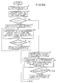
- FIGS. 6A and 6B are block diagrams showing the major process steps used for route calculation
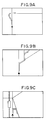
- FIG. 7A is a diagram which serves to explain the setting of a route retrieval area when the straight distance between the current location and the destination is short
- FIG. 7B is a schematic view which serves to explain the setting of route retrieval areas when that distance is long.
- step 1 of FIG. 6A the vehicle location detected by the locator 11 and the aforesaid destination are entered.
- step 2 when the current location or destination is in an alleyway, an automatic retrieve is not performed, and a node on the nearest artery from the current location is defined as the aforesaid starting end node (a), and a node on the nearest artery from the destination is defined as the aforesaid end point node (b).
- step 3 it is determined whether the straight distance L leading from the current location to the destination is longer than a predetermined distance x. This distance x is approximately 20 Km for metropolitan areas and approximately 30 Km for suburban areas.
- a rectangular area of the second layer containing the current location and the destination is set in step 4, as shown in FIG. 7A.
- a recommended route is calculated based on the evaluation function Fmi corresponding the route mode previously set.
- step 6 it is determined whether a recommended route to the end point node (b) is calculated or not.
- the rectangular area set in the step 4 is magnified, and the steps 5 and 6 are repeated. In this case, the number of magnifications of the area is limited in order to avoid an external loop.
- step 6 when it is determined that the recommended route has been calculated, the step 6 proceeds to the step 8 of FIG. 6B to complete the processing of the recommended route calculation.
- step 3 when it is determined that the straight distance L is longer than the predetermined distance x, the step 3 proceeds to step 9, and in the step 9 an square area containing the current location is set within the second layer, as shown in FIG. 7B.
- step 10 a node of the second mesh and a node of the first mesh that are connected with the starting point node (a) (hereinafter referred to as a starting-point-side interlayer connection node (c)) are searched for, and a recommended route from the starting point node (a) to the starting-point-side interlayer connection node (c) is calculated based on the evaluation function Fi.
- step 11 it is determined whether the recommended route to the starting-point-side interlayer connection node (c) has been calculated or not.
- step 9 When it is determined that the starting-point-side interlayer connection node (c) has not been calculated, the square area set in the step 9 is magnified in step 12 and the steps 10 and 11 are repeated. Also in this case, the number of magnifications of the square area is limited to avoid an external loop.
- step 11 determines that the recommended route to the starting-point-side interlayer connection node (c) has been calculated.
- the step 11 proceeds to the step 13 of FIG. 6B, and a rectangular area is set in the first layer, as shown in FIG. 7B.
- step 14 a recommended route from the starting-point-side interlayer connection node (c) to the end-point-side square area containing the destination is calculated based on the evaluation function Fmi set by the vehicle operator.
- step 15 it is determined whether or not the end-point-side square area has been reached (i.e., whether the recommended route has been calculated or not). When it is determined that the recommended route has not been calculated, the steps 13 and 14 are repeated.
- step 14 When the recommended route has been calculated in the aforesaid step 14, a node connected within the square area with the end-point node (b) (hereinafter referred to a end-point-side interlayer connection node (d)) is searched for in step 16, as shown in FIG. 7B.
- step 17 a recommended route from the end-point-side interlayer connection node (d) to the end point node (b) is calculated based on the evaluation function Fi set by the vehicle operator.
- step 18 it is determined whether a recommended route from the end-point-side interlayer connection node (d) to the second layer has been calculated or not. When the recommended route has not been calculated, the square area is magnified in step 19, and the steps 17 and 18 are repeated.
- the step 18 proceeds to the step 8 to complete the recommended route calculation.
- the area of the second mesh is defined to a rectangular area for a short distance route computation or an square area for a long distance route computation. Since only road net data within the aforesaid rectangular area are read in the case of the short distance route computation, the time needed for reading road net data can be reduced. In addition, since the recommended route is calculated by adding road segments in the defined area, the time needed for calculating the route leading from the starting point node (a) to the end point node (b) can be greatly reduced.
- the route between the starting point node (a) and the starting-point-side interlayer connection node (c) and the route between the end point node (b) and the end-point-side interlayer node (d) are calculated in the square area of the second mesh, and between the starting-point-side interlayer connection node (c) and the end-point-side interlayer node (d), the route is calculated in the high class layer (first layer) comprised of freeways and major arteries. Therefore, even if a route to be calculated is a long distance route, time needed for route computation can be greatly reduced.
- the route calculation device as above described can perform the following processes, in addition to the processes presented above. That is,
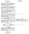
- FIG. 8 is a block diagram showing the major process steps used for route guidance.
- step 1 until a vehicle comes close to the starting point node (a), the vehicle location (e), the starting point node (a) and the road map containing the location (e) and the node (a) are displayed as shown in FIG. 4A.
- step 2 the approach of the vehicle to the starting point node (a) is monitored and detected.
- step 3 the road map containing the starting point node (a) is read from the map memory 3.
- step 4 the road map data read is converted to an enlarged display format which displays the road map containing the starting node (a), the vehicle location (e) and the recommended route (f) on the whole of the picture screen, as shown in FIG. 4B.
- step 5 the data converted to the enlarged display format is supplied to the second CPU 19.
- the second CPU 19 then writes the data converted to the enlarged display format to the frame memory 21, and causes the display 1 to display the road map containing the starting node (a), the vehicle location (e) and the recommended route (f) with the enlarged display format.
- step 6 the approach of the vehicle to a node to which the vehicle is to be guided next is monitored and detected.
- step 7 it is determined whether or not the node (n) that the vehicle is approaching is the end point node (b). If not the end point node (b), the step 7 proceeds to step 8, in which a road map containing the node (n) is read from the map memory 3, and the steps 4 and 5 are again performed. That is, the step 6 is repeated until the node (n) becomes the end point node (b).
- step 7 When, on the other hand, it is determined in the step 7 that the node (n) is the end point node (b), the end point node (b) is displayed in step 9 on a wide range of a road map, together with the destination.
- the step 9 proceeds to step 10 to complete the route guidance program.
- the route guidance system is adaptable to the case that a vehicle travels alleyways at relatively lower speeds or the case that a vehicle travels streets which are completely unknown to the vehicle operator.
- the route guidance system according to the present invention is also adaptable to roads such as arteries wherein it is necessary to judge the form of junctions momentarily while travelling at high speeds.
- roads such as arteries wherein it is necessary to judge the form of junctions momentarily while travelling at high speeds.
- the vehicle operator is able to know in a moment which road to select, because an optimum route is displayed with an enlarged display, together with the road map. Accordingly, the vehicle can be guided safe.
- the route guidance system according to the present invention is easy to confirm the directions of other roads relative to the travelling direction of the vehicle, and convenient in selecting a route.
- FIGS. 9A to 9C illustrate sophisticated junctions that are displayed in accordance with the route guidance system as above described.
- the vehicle operator can visually know that it is necessary to take the left vehicle lane in advance to turn to the right, as shown in FIG. 9A.
- the vehicle operator can easily follow the recommended route, since after the first intersection has been passed, the direction to which the vehicle travel at the next intersection is displayed, as shown in FIG. 9B.
- the vehicle can know in advance the roads around the station, and the distraction of worrying about becoming lost can be alleviated since the recommended route is displayed. It is also possible that, in a junction of simple form, the direction along the recommended route is displayed only.
- the present invention can provide a route desired by the vehicle operator, by allowing the vehicle operator to input a destination and desired route calculation conditions through the initialization means, and calculating a recommended route by the route calculation means on the basis of on the route calculation conditions inputted with the initialization means.
- the vehicle guidance means reads road map data containing that junction from the map memory means, and enlarges and displays the road map containing the junction, the vehicle location and the recommended route. Accordingly, the vehicle operator is able to easily know the travelling direction of the vehicle visually and drive the vehicle safe.
Description
- The present invention relates in general to an autonomous in-vehicle navigator, and in particular to such a navigator wherein, according to the setting of a destination by a vehicle operator, road map data containing the vehicle's current location and that destination is read from a map memory, and based on the road map data, a recommended route leading from the current location to the destination is calculated, and the vehicle is guided along the recommended route.
- There are known in-vehicle navigators that display routes, etc. on the picture screen of the display in order to meet the convenience of travel on unfamiliar areas, at night and the like. As conventional in-vehicle navigators, there are dead reckoning navigation and map matching navigation. The dead reckoning navigation is one wherein a display, direction sensor, distance sensor, map memory, computer and the like are mounted in a vehicle, the coordinate location of the vehicle is calculated based on the direction change data inputted from the direction sensor and the travel distance data inputted from the distance sensor, and this calculated coordinate location is displayed on the road map that is displayed on the picture screen of the display. The map matching navigation is one which further improves the navigator by the above dead reckoning navigation and wherein a vehicle location on the road is detected by matching the coordinate location of the vehicle with the road stored in the map memory, and this vehicle location is displayed on the road displayed on the picture screen.
- However, in both the above navigations, in order to guide a vehicle to a destination, the position of the destination is displayed on the road map that is picture displayed, and the route from the current location to the destination is judged by the vehicle operator.
- In very recent years, there has been proposed a navigator which guides a vehicle, by entering a destination and a desired route mode (for example, shortest distance route, shortest time route and so on) by the driver before travel, calculating a route from the current location to the destination by using a trip time or trip distance as a parameter, and displaying this calculated route on the road map that is picture displayed.
- As the above calculation method of the route from the current location to the destination, a so-called "Dijkstra" method has been adopted. This method assumes a net work leading from a starting point node to an end point node, successively adds all of the segments branching off from each node, and calculates a route that reaches the destination. If this method is used for route computation, the route leading from the current location to the destination will be obtained surely, as long as that route exists.
- As a vehicle guidance method, there are one method which guides a vehicle along a recommended route displayed a road map on a predetermined scale, and another method which guides a vehicle by displaying the vehicle direction only with an arrow having 8 to 16 directions.
- However, the above conventional methods have the following problems, since if the parameters of the route selection are time and distance only, a route is calculated based on either of two parameters that is selected by the vehicle operator.
- (1) If a route is calculated using the same parameter, a great number of vehicles are to travel the same route, and traffic jam (so-called hunting phenomenon) is rather incurred.
- (2) Since the amount of traffic varies depending upon environmental conditions such as time zone, traffic accident, road construction and the like, the shortest time route does not always become the shortest time route. As to the shortest distance route, the change of a route is unavoidable due to the unexpected conditions as above described. It is therefore little significant to set a parameter with one meaning.
- (3) It is often desired that a route mode be changed according to different preferences, ages and feelings of different vehicle operators. In the case that a parameter is set with one meaning, there is the problem that the route mode cannot be changed.
- In addition, if a route is calculated by the aforesaid "Dijkstra" method, and assuming each node has two branch paths relative to the travelling direction, the number of road segments is then increased exponentially. Therefore, in the case of a large number of nodes, there is the problem that a substantial time is required until the computation of a route is completed.
- Moreover, although, in the method for displaying a recommend route on a road map on a predetermined scale, it is possible to schematically grasp a vehicle location from the road map because the recommended route is displayed on the road map on a scale of about 1/10000, there is the problem that it is difficult to judge in a moment which direction to travel, when the vehicle is approaching a junction.
- Conversely, the method of displaying the travelling direction of a vehicle only with an arrow having 8 to 16 directions has a better visibility and can grasp momentary a route to be travelled, since it displays the vehicle direction with simple patterns. Further, the method has its advantage in that it has a small number of map data that are stored in the map memory, since the display form is simple. However, it cannot display junctions and the like wherein elevated roads and the like are combined complicatedly. In addition, since a road map is not displayed, the vehicle location on the road map cannot be judged. Furthermore, in the case of searching in a strange area for a destination, there is the problem that the destination cannot be searched for in the display of the forms of junctions.
- As previously described, both the method wherein a recommended route is displayed on a road map on a predetermined scale and the method wherein the travelling direction of a vehicle is displayed only with an arrow having 8 to 16 directions, have merits and demerits. In addition, there is the problem that different displays are needed depending upon attributes of different roads (major artery or not), attributes of different junctions (complicated shape or not), area unfamiliarities of vehicle operators, and the like.
- Examples of known navigator systems are disclosed e.g. In GB-A-2 079 453, GB-A-2 100 001 and EP-A-0 246 452.
- Accordingly, it is an object of the present invention to provide an improved in-vehicle navigator which makes it possible to vary the parameters requested for route computation in accordance with the preferences of a vehicle operator.
- Another object of the present invention is to provide an improved in-vehicle navigator which makes it possible to alleviate traffic jam.
- Still another object is to provide an improved in-vehicle navigator which makes it possible to reduce the time required for route computation.
- Yet another object of the present invention is to provide an improved in-vehicle navigator which is capable of different displays in accordance with attributes of roads, attributes of junctions, and area unfamiliarities of vehicle operators.
- In order to achieve the above objects, as shown in FIG. 1, the in-vehicle navigation of this invention comprises:
map memory means (A) for memorizing road map data consisting of road data comprised of the combination of nodes and links, and background data such as buildings;
location detection means (B) for detecting a vehicle location;
initialization means (C) for inputting a destination and a route calculation condition, said initialisation means being arranged such that the calculation condition can either be selected by a vehicle operator from a plurality of pre-stored route calculation conditions determined based on an evaluation function Fi = Σ (ami x Am) where i is a route mode number,
Σ (am) = 1, am (m = 1, 2..... 5) is a weighted ratio of Am which is - A1: total trip time of route,
- A2: total trip distance of route ÷ speed coefficient,
- A3: total trip cost of route ÷ unit time cost coefficient,
- A4: (total number of left turns of route x left turn time coefficient) + (total number of right turns of route x right turn time coefficient), and
- A5: number of passings of signal x passing time, or can be input by the vehicle operator as a varied route calculation condition, which is obtained by varying a weighted ratio am of said evaluation function to a desired value of said vehicle operator;
route calculation means (D) for reading road map data containing a current location and said destination from said map memory means (A), and for calculating a recommended route, based on said read road map data and said selected pre-stored or varied route calculation condition imputed by said initialization means (C);
memory means (E) for storing said recommended route; and
vehicle guidance means (F) for detecting an approach to a junction on said recommended route, based on said vehicle location detected by said location detection means (B), and for reading road map data containing said junction from said map memory means (A), and for enlarging and displaying the road map containing said junction, together with said vehicle location and said recommended route;
wherein said road map data stored in said map memory means (A) is classified in accordance with road classification from a highest class map wherein spacing between said nodes of said road data is widest to a lowest class map wherein spacing between said nodes of said road data is narrowest, and wherein said route calculation means (E) defines a route retrieval area, based on a straight distance leading from said current location to said destination, and if said route retrieval area is in the same class map, calculates a recommended route by adding within the same class map the links leading from a node (a) nearest to said current location to a node (b) nearest to said destination, and if said route retrieval area is not in the same class, retrieves from said road data a current-location-side connection node (c) connecting a lower class map and a higher class map and a destination-side connection node (d) connecting said lower class map and said higher class map, and
calculates a recommended route leading from a node (a) nearest to said current location to a node (b) nearest to said destination by the sum of a route of said lower class map from said node (a) nearest to said current location to said current-location-side connection node (c), a route of said lower class map from said node (b) nearest to said destination to said destination-side connecting node (d) and a route of said higher class map from said current-location-side connection node (c) to said destination-side connection node (d). - The aforesaid vehicle guidance means (F) may display on the road map a starting point of said recommended route calculated by said route calculation means (D) and said vehicle location until the vehicle reaches said starting point, displays said recommended route, said vehicle location and form of said junction on the whole of a picture screen or a window of said picture screen during travel of said recommended route, and displays on the road map said destination and said vehicle location during travel from an end point of said recommended route to said destination.
- The aforesaid vehicle guidance means (F) may perform a display of road map and vehicle location or a display of recommended route, vehicle location and junction form or a display of the combination of road map, recommended route, vehicle location and junction form, depending upon attributes of road, attributes of junctions and unfamiliarities of areas of said vehicle operator.
- The above and other objects and advantages will become apparent from the following detailed description when read in conjunction with the accompanying drawings wherein:
- Fig 1 is a block diagram illustrating schematically the principle of an in-vehicle navigator according to the present invention;
- Fig 2 is a block diagram illustrating schematically an embodiment of the in-vehicle navigator according to the present invention;
- Fig 3 illustrates the hardware of the route calculation part, main memory and output controller of Fig 2;
- Fig 4a shows a display form before the vehicle approaches the starting point node of the recommended route;
- Fig 4b shows another display form at the time the vehicle has approached the starting point node;
- Figs 5a and 5b show initialisation menus displayed on the picture screen of the video display of Fig 2, respectively;
- Fig 5c shows a first layer road map comprised of freeways and major arteries;
- Fig 5d shows a second layer road map comprised of freeways, major arteries and minor arteries;
- Fig 5e shows a third layer road map comprised of all streets containing alleyways;
- FIG. 5F shows a display of a vehicle current location after the initialization has been inputted;
- FIGS. 6A and 6B are block diagrams showing the major process steps used for route calculation;
- FIG. 7A is a diagram which serves to explain the setting of a route retrieval area when the straight distance between the current location and the destination is short;
- FIG. 7B is a schematic view which serves to explain the setting of route retrieval areas when the straight distance between the current location and the destination is long;
- FIG. 8 is a block diagram showing the major process steps used for route guidance; and
- FIGS. 9A through 9C show graphic displays of sophisticated junctions that are displayed on the picture screen in accordance with the embodiment of the in-vehicle navigator according to the present invention.
- Referring now in greater detail to the drawings and initially to FIG. 2, there is shown a preferred embodiment of an in-vehicle navigator in accordance with the present invention.
- The in-vehicle navigator comprises a
video display 1, aconsole 2, amap memory 3, amemory drive 4, atouch panel 5, aninitialization part 6, aroute calculation part 7, amain memory 8, adistance sensor 9, adirection sensor 10, alocator 11, anoutput controller 12, and an input/output interface 13.Reference numeral 14 indicates a communication device for receiving road information transmitted from a control station, and 15 indicates an audio output device for informing a vehicle operator that the vehicle is approaching an intersection. - The
video display 1 displays textual and line graphic information such as initialization menus, road maps, vehicle location, recommended routes and the like, at the predetermined dot positions. As thisvideo display 1, a CRT (Cathode Ray Tube) display, crystalline panel display or the like can be employed. - The
console 2 has a keyboard (not shown) which allows a vehicle operator to start and stop this device, and to move a cursor on the picture screen of thedisplay 1 and to scroll the road map displayed on the picture screen. - The
map memory 3 divides Japanese road map into mesh blocks, and stores road map data consisting of road data comprised of the combination of nodes and links, and background data such as buildings and the like. This road map data are used for graphic display and route calculation. As thismap memory 3, a mass storage medium memory such as a CD-ROM, magnetic tape and the like can be employed. - A more detailed description of the
above map memory 3 will be given hereinafter. - The
map memory 3 divides Japanese road map on a scale of 1/2500 or 1/10000 with a longitude difference of 1 degree and a latitude difference of 40 minutes, and is comprised of a first mesh (FIG. 5C) having longitudinal and lateral distances of about 80 Km x 80 Km, a second mesh (FIG. 5D) that is 1/64 of the first mesh and thus has longitudinal and lateral distances of about 10 Km x 10 Km, and a third mesh (FIG. 5E) that is 1/100 of the second mesh and thus has longitudinal and lateral distances of about 1 Km x 1 Km. The road net data of the first mesh through the third mesh are grouped into three classes of a first layer through a third layer. The roads of the first layer are comprised of freeways and major arteries. The roads of the second layer are comprised of the roads of the first layer and minor arteries. The roads of the third layer are comprised of all streets including alleyways. - The nodes comprise junction nodes and auxiliary nodes disposed between the junction nodes. As node data, there are a node number, address of the node of the high class or low class mesh corresponding to the node number or addresses of the nodes of the surrounding meshes corresponding to the node number, addresses of the surrounding nodes, addresses of links connected to nodes, and so on.
- The link data are a link number, addresses of link starting point and link end point nodes, link distance, time data needed for travelling a link, road classification (freeways, arteries, streets), road width, traffic restrictions such as one-way streets, turn restrictions, toll roads, and so on.
- The background data contain railways, rivers, place-names, famous facilities, spots prestored by a vehicle operator, contours and the like. The contours are generally not displayed, but employed as data at the time of a route mode initialization. It is noted that the spacing between the nodes can be set to a further reduced spacing, depending upon the capacity of the
map memory 3 or the processing speed of theroute calculation part 7. - The
touch panel 5 is attached on the picture screen of thedisplay 1, has transference electrodes arranged with identical patterns in the form of a matrix, and outputs the position touched by a vehicle operator to theinitialization part 6. - The
initialization part 6 causes thedisplay 1 to display a road map for inputting a destination, a plurality of route modes based on an evaluation function Fi defined by the following equation (I), and numerals for varying the value of a weighted ratio αm of the evaluation function Fi, and causes a vehicle operator to touch the display position to input a destination and a desired route mode.
where i is a route mode number, Σ (αm) = 1, αm (m =1, 2, ... n) is a weighted ratio of Am, and Am is - A1: total trip time of route,
- A2: total trip distance of route ÷ speed coefficient,
- A3: total trip cost of route ÷ unit time cost coefficient,
- A4: (total number of left turns of route x left turn time coefficient) + (total number of right turns of route x right turn time coefficient), and
- A5: number of passings of signal x signal passing time.
- More particularly, the setting and the like of the aforesaid destination and evaluation function Fi are performed according to initialization menus displayed on the
display 1. As these initialization menus, there are - (1) Spot setting menu: It displays a road map, and causes a vehicle operator to touch the position of a destination on the displayed road map and also the positions of progress points on the route.
- (2) Route mode setting menu: It displays multiple sorts of route modes corresponding to the evaluation function Fi whose weighted ratio αm has been prestored by the vehicle operator, and causes the vehicle operator to touch the position of a desired route mode. As the route modes, there are a mode that has a preference to a shortest time route wherein the weighted ratio α1 of the time parameter A1 of the evaluation function Fi has been rendered greatest, a mode that has a preference to a shortest distance route wherein the weighted ratio α2 of the distance parameter A2 has been rendered greatest, a mode that has a preference to a minimum cost route wherein the weighted ratio α3 of the trip cost parameter A3 has been rendered greatest, and a mode that has a preference to a least right and left turn route wherein the weighted ratio α4 of the number of right and left turns has been rendered greatest. In addition to the above route modes, there are a route mode having a preference to sightseeing resorts, a route mode having a preference to roads familiar to a vehicle operator, a route mode having a preference to roads along mountains, a route mode having a preference to roads along coast lines, and a route mode having a preference to wider roads. The route modes as above described can be inputted in accordance with the link data (type, distance, trip time, etc.) and the background data (place-name, famous facility, contour, etc.).
- (3) Ratio setting menu: It displays the values of the weighted ratios for varying the content of the evaluation function Fi, and causes the vehicle operator to touch the value of a desired weighted ratio. If, for example, 1 is selected for the weighted ratio α1, the evaluation function Fi becomes Fi = A1, and a route calculated becomes a shortest time route.
- (4) Other setting menus: There is a menu that displays the sort of a display form such as a rotation mode which fixes the travelling direction of a vehicle and rotates the surrounding map on the vehicle, a fixed mode which fixes a map in the north direction, and the like. The vehicle operator touches the position of a desired display mode to input that mode.
- It is noted that the aforesaid destination may also be inputted through the keyboard of the
console 2. In this case, the destination may also be inputted by selecting it from the spot data such as the place name list, famous facility list, and spots prestored by the vehicle operator. In addition, it is possible that a vehicle operator himself or herself designates progress spots on the route. - In accordance with the destination setting by the vehicle operator, the
route calculation part 7 reads from the map memory 3 a predetermined range of road map data containing a node on an artery nearest to the vehicle current location detected by the locator 11 (hereinafter referred to as a starting point node) and a node on an artery nearest to the destination (hereinafter referred to as an end point node). Theroute calculation part 7 then calculates a recommended route leading from the starting node to the end point node, under the condition of the evaluation function Fi corresponding to the route mode inputted by the vehicle operator and according to the aforesaid "Dijkstra" method. In addition, theroute calculation part 7 varies the content of the evaluation function Fi according to the value of the weighted ratio αm inputted by the vehicle operator, and based on this varied evaluation function, calculates a recommended route leading from the starting point node to the end point node. The calculation of this recommended route is performed by, based on the node addresses of the high class mesh respectively connected to the starting point and end point nodes, searching for the nodes of the high class mesh, and by using the road map data of the high class mesh. - The
main memory 8 temporarily stores the recommended route calculated by theroute calculation part 7. Concretely, it stores the junction nodes. - The
locator 11 has a map memory 11a for location detection and a microcomputer 11b. The map memory 11a for location detection stores the addresses of divided nodes that divide all the roads in a predetermined range (for example, road map on a scale of 1/500) at intervals of a predetermined distance, addresses of junction nodes, and addresses of the surrounding nodes related to each node. The position of the nodes is determined corresponding to paths that a vehicle actually travels. The microcomputer 11b of thelocator 11 calculates travel track data by integrating the distance data detected by thedistance sensor 9 and integrating the direction change data detected by thedirection sensor 10, and detects the vehicle location, based on the similarity of this calculated travel track data and the road patterns stored in the location-detection map memory 11a. The direction sensor detects changes in the direction of a vehicle during travel, and may comprise a terrestrial magnetism sensor, gyro, vehicle wheel speed sensors for detecting an angle of turn from the difference between the number of rotations of left and right vehicle wheels, or the like. Thedistance sensor 9 detects the distance that a vehicle has travelled, from the vehicle speed or the number of rotations of the vehicle wheel and may comprise vehicle wheel speed sensors, vehicle speed sensors or the like. It is also possible that the map memory 11a for location detection and themap memory 3 are employed in common. - FIG. 3 shows the hardware structure of the aforesaid
route calculation part 7,main memory 8 andoutput controller 12. To abus line 16 are connected themain memory 8, a first read-only memory (first ROM) 17 that stores programs for route calculation, asecond ROM 18 that stores programs for route guidance, a first central processing unit (first CPU) 19 that executes the recommended route calculation and the route guidance on the basis of the route calculation programs and the route guidance programs, the input/output interface 13, and asecond CPU 20 for display. To thesecond CPU 20 for display is connected aframe memory 21. To the input/output interface 13 is connected thecommunication device 14 and theaudio output device 15. That is, thefirst ROM 17,second ROM 18 andfirst CPU 19 perform the route calculation and the route guidance. Thesecond CPU 20, and theoutput controller 12 comprised of theframe memory 21 display road maps and the like with a predetermined form. - The
first CPU 19 determines the evaluation function Fi according to the selected or varied route mode from theinitialization part 6. In addition, in accordance with the destination selected by the vehicle operator, thefirst CPU 19 reads the road net data containing the starting point and end point nodes from the map memory 3 (the first layer or second layer is used). Thereafter, based on the determined evaluation function Fi, thefirst CPU 19 calculates a recommended route leading from the starting point node to the end point node. Based on information on traffic jam and the like inputted from thecommunication device 14, thefirst CPU 19 also calculates a new recommended route. The recommended route calculated by thefirst CPU 19 is stored temporarily in themain memory 8, and each time the vehicle approaches the starting point node, end point node or junctions that have been stored in themain memory 8, the road map data containing junctions are read from themap memory 3. This road map data is format converted to the rotation display data that is used in the rotation mode which fixes the travelling direction of a vehicle and rotates the surrounding map on the vehicle location, and also format converted to a display form of better visibility, and then transmitted to theoutput controller 12. In addition, thefirst CPU 19 outputs a warning signal to theaudio output device 15, which then produces a warning audio chime that the vehicle is approaching junctions. - The
second CPU 20 writes the road map data, which has been format converted by thefirst CPU 19, to theframe memory 21, and causes thedisplay 1 to display that road map data. - FIGS. 4A and 4B are diagrams which serve to explain the display form as above described. FIG. 4A is a diagram showing a display form before a vehicle approaches the starting node (a), while FIG. 4B is a diagram showing a display form at the time a vehicle has approached the starting node (a). That is, when the vehicle is in a position spaced apart a predetermined distance from the starting point node (a), a wide range of a road map is displayed, while if the vehicle comes close to the starting point node (a), a road map containing the starting point node (a), vehicle location (e), and recommended route (f) are displayed with an enlarged scale, as shown in FIG. 4B. It is noted that, by providing a window in the picture screen of the
display 1, a display form of better visibility may also be displayed inside the window, and a wide range of a road map displayed outside the window. - The operation of the in-vehicle navigator constructed as described above will hereinafter be described in detail, making reference to FIGS. 5 through 8.
- The initialization operation will be as follows.
- (1) As shown in FIG. 5A, there are listed a mode having a preference to a shortest time route, a mode having a preference to a shortest distance route, a mode having a preference to a minimum cost route, and the like. The vehicle operator touches the position of a desired mode to select a mode for route calculation from the list displayed by the
display 1. - (2) After the selection of the desired mode, the vehicle operator determines whether a weighted ratio is varied or not, as shown in FIG. 5B. If the answer of the vehicle operator is "NO", a recommended route is selected with the previous mode. If "YES", the weighted ratio αm and numerals for setting that ratio αm are displayed. The vehicle operator touches the position of a desired numeral.
- (3) The weighted ratio αm of the evaluation function Fi is then varied according to the numeral selected by the vehicle operator.
- (4) Thereafter, the road map of the first layer is displayed as shown if FIG. 5C. In the case that the above input processes (1) to (3) are omitted and this input process (4) is performed, a route mode that has been selected from the route modes of the input process (1) by the vehicle operator is selected.
- (5) The vehicle operator touches the position of the mesh of the first layer containing the destination to select the mesh of the second layer containing that destination. The road map of the second layer selected is then displayed, as shown in FIG. 5D.
- (6) The position of the mesh of the second layer containing the destination is touched to select the mesh of the third layer containing the destination. That position of the mesh of the selected third layer may be selected as a destination. Then, the central portion of the road map of the selected third layer is displayed, as shown in FIG. 5E.
- (7) The position of the destination is searched for and touched by scrolling the road map of the third layer, as shown in FIG. 5E.
- (8) After the initialization has been performed in the way as above described, the display of FIG. 5E is returned back to the display of the current location of the vehicle, as shown in FIG. 5F and the calculation of the recommend route is performed.
- FIGS. 6A and 6B are block diagrams showing the major process steps used for route calculation, FIG. 7A is a diagram which serves to explain the setting of a route retrieval area when the straight distance between the current location and the destination is short, and FIG. 7B is a schematic view which serves to explain the setting of route retrieval areas when that distance is long.
- In
step 1 of FIG. 6A, the vehicle location detected by thelocator 11 and the aforesaid destination are entered. Instep 2, when the current location or destination is in an alleyway, an automatic retrieve is not performed, and a node on the nearest artery from the current location is defined as the aforesaid starting end node (a), and a node on the nearest artery from the destination is defined as the aforesaid end point node (b). Instep 3, it is determined whether the straight distance L leading from the current location to the destination is longer than a predetermined distance x. This distance x is approximately 20 Km for metropolitan areas and approximately 30 Km for suburban areas. When it is determined that the straight distance L is shorter than the predetermined distance x, a rectangular area of the second layer containing the current location and the destination is set instep 4, as shown in FIG. 7A. Instep 5, a recommended route is calculated based on the evaluation function Fmi corresponding the route mode previously set. Instep 6, it is determined whether a recommended route to the end point node (b) is calculated or not. When it is determined that the recommended route to the end point node (b) has not been calculated, the rectangular area set in thestep 4 is magnified, and thesteps - In the
above step 6, when it is determined that the recommended route has been calculated, thestep 6 proceeds to thestep 8 of FIG. 6B to complete the processing of the recommended route calculation. - In the
above step 3, when it is determined that the straight distance L is longer than the predetermined distance x, thestep 3 proceeds to step 9, and in thestep 9 an square area containing the current location is set within the second layer, as shown in FIG. 7B. Instep 10, a node of the second mesh and a node of the first mesh that are connected with the starting point node (a) (hereinafter referred to as a starting-point-side interlayer connection node (c)) are searched for, and a recommended route from the starting point node (a) to the starting-point-side interlayer connection node (c) is calculated based on the evaluation function Fi. Instep 11, it is determined whether the recommended route to the starting-point-side interlayer connection node (c) has been calculated or not. When it is determined that the starting-point-side interlayer connection node (c) has not been calculated, the square area set in thestep 9 is magnified instep 12 and thesteps aforesaid step 11 it is determined that the recommended route to the starting-point-side interlayer connection node (c) has been calculated, thestep 11 proceeds to thestep 13 of FIG. 6B, and a rectangular area is set in the first layer, as shown in FIG. 7B. Instep 14, a recommended route from the starting-point-side interlayer connection node (c) to the end-point-side square area containing the destination is calculated based on the evaluation function Fmi set by the vehicle operator. Instep 15, it is determined whether or not the end-point-side square area has been reached (i.e., whether the recommended route has been calculated or not). When it is determined that the recommended route has not been calculated, thesteps - When the recommended route has been calculated in the
aforesaid step 14, a node connected within the square area with the end-point node (b) (hereinafter referred to a end-point-side interlayer connection node (d)) is searched for instep 16, as shown in FIG. 7B. Instep 17, a recommended route from the end-point-side interlayer connection node (d) to the end point node (b) is calculated based on the evaluation function Fi set by the vehicle operator. Instep 18, it is determined whether a recommended route from the end-point-side interlayer connection node (d) to the second layer has been calculated or not. When the recommended route has not been calculated, the square area is magnified instep 19, and thesteps step 18 it is determined that the recommended route has been calculated, thestep 18 proceeds to thestep 8 to complete the recommended route calculation. - As previously described, in the recommended route calculation according to the present invention, based on the straight distance leading from the current location to the destination, the area of the second mesh is defined to a rectangular area for a short distance route computation or an square area for a long distance route computation. Since only road net data within the aforesaid rectangular area are read in the case of the short distance route computation, the time needed for reading road net data can be reduced. In addition, since the recommended route is calculated by adding road segments in the defined area, the time needed for calculating the route leading from the starting point node (a) to the end point node (b) can be greatly reduced. In the case of the long distance route computation, the route between the starting point node (a) and the starting-point-side interlayer connection node (c) and the route between the end point node (b) and the end-point-side interlayer node (d) are calculated in the square area of the second mesh, and between the starting-point-side interlayer connection node (c) and the end-point-side interlayer node (d), the route is calculated in the high class layer (first layer) comprised of freeways and major arteries. Therefore, even if a route to be calculated is a long distance route, time needed for route computation can be greatly reduced.
- The route calculation device as above described can perform the following processes, in addition to the processes presented above. That is,
- (1) It is also possible that the starting point node (a) and the end point node (b) are set on any road segment of alleyways and the like. However, if these nodes are set on alleyways, a traffic jam will be rather incurred because vehicles take a long way around the alleyways. Therefore, the starting point node (a) and the end point node (b) are set in general on arteries.
- (2) If a vehicle current location and a destination are on arteries, the current location is set as the starting point node (a) and the destination set as the end point node (b).
- (3) The recommended route between the starting point node (a) and the starting-point-side interlayer connection node (c), and the recommended route between the end point node (b) and the end-point-side interlayer connection node (d) are first calculated. Thereafter, the route between the starting-point-side interlayer connection node (c) and the end-point-side interlayer node (d) is calculated.
- (4) Recalculation is performed while travelling.
- (5) A vehicle operator specifies junctions on alleyways, based on a road map, and then sets a route from the current location to the starting point node (a) or a route from the destination to the end point node (b).
- (6) When traffic information such as traffic jam, accidents, road construction and the like are obtained from a control station, a recommended route to which bypasses and the like are added is calculated, taking such information into account.
- FIG. 8 is a block diagram showing the major process steps used for route guidance.
- In
step 1, until a vehicle comes close to the starting point node (a), the vehicle location (e), the starting point node (a) and the road map containing the location (e) and the node (a) are displayed as shown in FIG. 4A. Instep 2, the approach of the vehicle to the starting point node (a) is monitored and detected. Instep 3, the road map containing the starting point node (a) is read from themap memory 3. Instep 4, the road map data read is converted to an enlarged display format which displays the road map containing the starting node (a), the vehicle location (e) and the recommended route (f) on the whole of the picture screen, as shown in FIG. 4B. Instep 5, the data converted to the enlarged display format is supplied to thesecond CPU 19. Thesecond CPU 19 then writes the data converted to the enlarged display format to theframe memory 21, and causes thedisplay 1 to display the road map containing the starting node (a), the vehicle location (e) and the recommended route (f) with the enlarged display format. Instep 6, the approach of the vehicle to a node to which the vehicle is to be guided next is monitored and detected. Instep 7, it is determined whether or not the node (n) that the vehicle is approaching is the end point node (b). If not the end point node (b), thestep 7 proceeds to step 8, in which a road map containing the node (n) is read from themap memory 3, and thesteps step 6 is repeated until the node (n) becomes the end point node (b). When, on the other hand, it is determined in thestep 7 that the node (n) is the end point node (b), the end point node (b) is displayed instep 9 on a wide range of a road map, together with the destination. Thestep 9 proceeds to step 10 to complete the route guidance program. - According to the route guidance as above described, between the current location and the starting point node (a) of the recommended route, the vehicle location and the starting point node (a) are displayed together with the road map, and between the end point node (b) of the recommended route and the destination, the vehicle location and the destination are displayed be together with the road map. Therefore, since the vehicle location is grasped in a wider region, the route guidance system according to the present invention is adaptable to the case that a vehicle travels alleyways at relatively lower speeds or the case that a vehicle travels streets which are completely unknown to the vehicle operator. In addition, since each junction is displayed with a better visibility form between the starting point node (a) of the recommended route and the end point node (b) of the recommended route, the route guidance system according to the present invention is also adaptable to roads such as arteries wherein it is necessary to judge the form of junctions momentarily while travelling at high speeds. Particularly, in the intersection having a plurality of branch paths as shown in FIG. 4B, the vehicle operator is able to know in a moment which road to select, because an optimum route is displayed with an enlarged display, together with the road map. Accordingly, the vehicle can be guided safe. Moreover, since the road map or recommended route is rotated on the vehicle location and displayed, the route guidance system according to the present invention is easy to confirm the directions of other roads relative to the travelling direction of the vehicle, and convenient in selecting a route.
- FIGS. 9A to 9C illustrate sophisticated junctions that are displayed in accordance with the route guidance system as above described. In an elevated junction wherein a vehicle is required to travel a left vehicle lane in order to turn to the right, the vehicle operator can visually know that it is necessary to take the left vehicle lane in advance to turn to the right, as shown in FIG. 9A. Even in the case a plurality of junctions continue, the vehicle operator can easily follow the recommended route, since after the first intersection has been passed, the direction to which the vehicle travel at the next intersection is displayed, as shown in FIG. 9B. In the sophisticated intersection around a railway station as shown in FIG. 9C, the vehicle can know in advance the roads around the station, and the distraction of worrying about becoming lost can be alleviated since the recommended route is displayed. It is also possible that, in a junction of simple form, the direction along the recommended route is displayed only.
- From the foregoing description, it will be seen that the present invention can provide a route desired by the vehicle operator, by allowing the vehicle operator to input a destination and desired route calculation conditions through the initialization means, and calculating a recommended route by the route calculation means on the basis of on the route calculation conditions inputted with the initialization means. Each time the vehicle approaches the junction of the recommended route stored in the memory means, the vehicle guidance means reads road map data containing that junction from the map memory means, and enlarges and displays the road map containing the junction, the vehicle location and the recommended route. Accordingly, the vehicle operator is able to easily know the travelling direction of the vehicle visually and drive the vehicle safe.
- The invention has been described with reference to the preferred embodiment. Obviously modifications and alternations will occur to others upon a reading and understanding of this application. It is intended to include all such modifications and alternations insofar as they come within the scope of the appended claims.
Claims (3)
- An in-vehicle navigator comprising: map memory means (A) for storing road map data consisting of road data comprised of the combination of nodes and links, and background data such as buildings;
location detections means (B) for detecting a vehicle location;
initialization means (C) for inputting a destination and a route calculation condition, said initialisation means being arranged such that the calculation condition can either be selected by a vehicle operator from a plurality of pre-stored route calculation conditions determined based on an evaluation function Fi = Σ (ami x Am) where i is a route mode number, Σ (am) = 1, am (m = 1, 2..... 5) is a weighted ratio of Am which isA1: total trip time of route,A2: total trip distance of route ÷ speed coefficient,A3: total trip cost of route ÷ unit time cost coefficient,A4: (total number of left turns of route x left turn time coefficient) + (total number of right turns of route x right turn time coefficient), andA5: number of passings of signal x passing time, or can be input by the vehicle operator as a varied route calculation condition, which is obtained by varying a weighted ratio am of said evaluation function to a desired value of said vehicle operator;route calculation means (D) for reading road map data containing a current location and said destination from said map memory means (A), and for calculating a recommended route, based on said read road map data and said selected pre-stored or varied route calculation condition imputed by said initialization means (C);
memory means (E) for storing said recommended route; and
vehicle guidance means (F) for detecting an approach to a junction on said recommended route, based on said vehicle location detected by said location detection means (B), and for reading road map data containing said junction from said map memory means (A), and for enlarging and displaying the road map containing said junction, together with said vehicle location and said recommended route;
wherein said road map data stored in said map memory means (A) is classified in accordance with road classification from a highest class map wherein spacing between said nodes of said road data is widest to a lowest class map wherein spacing between said nodes of said road data is narrowest, and wherein said route calculation means (E) defines a route retrieval area, based on a straight distance leading from said current location to said destination, and if said route retrieval area is in the same class map, calculates a recommended route by adding within the same class map the links leading from a node (a) nearest to said current location to a node (b) nearest to said destination, and if said route retrieval area is not in the same class, retrieves from said road data a current-location-side connection node (c) connecting a lower class map and a higher class map and a destination-side connection node (d) connecting said lower class map and said higher class map, and calculates a recommended route leading from a node (a) nearest to said current location to a node (b) nearest to said destination by the sum of a route of said lower class map from said node (a) nearest to said current location to said current-location-side connection node (c), a route of said lower class map from said node (b) nearest to said destination to said destination-side connecting node (d) and a route of said higher class map from said current-location-side connection node (c) to said destination-side connection node (d). - An in-vehicle navigator as set forth in claim 1, wherein said vehicle guidance means (F) displays on the road map a starting point of said recommended route calculated by said route calculation means (D) and said vehicle location until the vehicle reaches said starting point, displays said recommended route, said vehicle location and form of said junction on the whole of a picture screen or a window of said picture screen during travel of said recommended route, and displays on the road map said destination and said vehicle location during travel from an end point of said recommended route to said destination.
- An in-vehicle navigator as set forth in claim 1, wherein said vehicle guidance means (F) performs a display of road map and vehicle location or a display of recommended route, vehicle location and junction form or a display of the combination of road map, recommended route, vehicle location and junction form, depending upon attributes of road, attributes of junctions and unfamiliarities of areas of said vehicle operator.
Applications Claiming Priority (6)
| Application Number | Priority Date | Filing Date | Title |
|---|---|---|---|
| JP30756388 | 1988-12-05 | ||
| JP307564/88 | 1988-12-05 | ||
| JP30756488 | 1988-12-05 | ||
| JP307563/88 | 1988-12-05 | ||
| JP88441/89 | 1989-04-07 | ||
| JP1088441A JP2716058B2 (en) | 1988-12-05 | 1989-04-07 | In-vehicle navigator |
Publications (3)
| Publication Number | Publication Date |
|---|---|
| EP0372840A2 EP0372840A2 (en) | 1990-06-13 |
| EP0372840A3 EP0372840A3 (en) | 1992-04-15 |
| EP0372840B1 true EP0372840B1 (en) | 1995-11-02 |
Family
ID=27305808
Family Applications (1)
| Application Number | Title | Priority Date | Filing Date |
|---|---|---|---|
| EP89312522A Expired - Lifetime EP0372840B1 (en) | 1988-12-05 | 1989-11-30 | Adaptive in-vehicle route guidance system |
Country Status (3)
| Country | Link |
|---|---|
| US (1) | US5031104A (en) |
| EP (1) | EP0372840B1 (en) |
| DE (1) | DE68924697T2 (en) |
Cited By (1)
| Publication number | Priority date | Publication date | Assignee | Title |
|---|---|---|---|---|
| DE102005004202B4 (en) * | 2005-01-29 | 2013-07-25 | Volkswagen Ag | Display device for a data processing device in a vehicle |
Families Citing this family (206)
| Publication number | Priority date | Publication date | Assignee | Title |
|---|---|---|---|---|
| GB2237905A (en) * | 1989-10-13 | 1991-05-15 | Plessey Co Plc | Road network navigation systems |
| DE4008460A1 (en) * | 1990-03-16 | 1991-09-19 | Bosch Gmbh Robert | NAVIGATION SYSTEM |
| US5293163A (en) * | 1990-06-06 | 1994-03-08 | Mazda Motor Corporation | Navigation apparatus for vehicles |
| US5428544A (en) * | 1990-11-05 | 1995-06-27 | Norm Pacific Automation Corporation | Traffic information inter-vehicle transference and navigation system |
| US5416477A (en) * | 1990-11-06 | 1995-05-16 | Matsushita Electric Industrial Co., Ltd. | Navigation system mounted on vehicle |
| EP0485120B1 (en) * | 1990-11-09 | 1998-07-29 | Sumitomo Electric Industries, Limited | Optimum route determination apparatus |
| US5274560A (en) * | 1990-12-03 | 1993-12-28 | Audio Navigation Systems, Inc. | Sensor free vehicle navigation system utilizing a voice input/output interface for routing a driver from his source point to his destination point |
| US5748840A (en) * | 1990-12-03 | 1998-05-05 | Audio Navigation Systems, Inc. | Methods and apparatus for improving the reliability of recognizing words in a large database when the words are spelled or spoken |
| US5454062A (en) * | 1991-03-27 | 1995-09-26 | Audio Navigation Systems, Inc. | Method for recognizing spoken words |
| US5592389A (en) * | 1990-12-03 | 1997-01-07 | Ans, Llp | Navigation system utilizing audio CD player for data storage |
| WO1992014215A1 (en) * | 1991-02-01 | 1992-08-20 | Peterson Thomas D | Method and apparatus for providing shortest elapsed time route information to users |
| US5394332A (en) * | 1991-03-18 | 1995-02-28 | Pioneer Electronic Corporation | On-board navigation system having audible tone indicating remaining distance or time in a trip |
| JP2874397B2 (en) * | 1991-03-19 | 1999-03-24 | 松下電器産業株式会社 | Route selection device |
| JP2891793B2 (en) * | 1991-04-12 | 1999-05-17 | パイオニア株式会社 | In-vehicle navigation device |
| JPH04319619A (en) * | 1991-04-19 | 1992-11-10 | Mitsubishi Electric Corp | Vehicle-borne navigation system |
| US5272638A (en) * | 1991-05-31 | 1993-12-21 | Texas Instruments Incorporated | Systems and methods for planning the scheduling travel routes |
| US5467276A (en) * | 1991-06-05 | 1995-11-14 | Tsuyuki; Toshio | Navigation apparatus and method |
| FR2677756B1 (en) * | 1991-06-13 | 1995-04-28 | Peugeot | METHOD AND DEVICE FOR CALCULATING A NAVIGATION ROUTE, IN PARTICULAR FOR A MOTOR VEHICLE. |
| US5442557A (en) * | 1991-07-26 | 1995-08-15 | Pioneer Electronic Corporation | Navigation device |
| JP2955073B2 (en) * | 1991-08-05 | 1999-10-04 | ビステオン・テクノロジーズ,エル・エル・シー | Vehicle navigation system |
| EP0534533B1 (en) * | 1991-09-25 | 1997-02-05 | Koninklijke Philips Electronics N.V. | Device and method for displaying cartographic information in vehicular navigation |
| JP2554567B2 (en) * | 1991-10-02 | 1996-11-13 | スタンレー電気株式会社 | How to display road information |
| US5544060A (en) * | 1991-10-16 | 1996-08-06 | Zexel Usa Corporation | Vehicle mounted navigation system with preview function |
| US5654892A (en) * | 1991-10-18 | 1997-08-05 | Zexel Usa Corporation | Navigation system displaying forthcoming turns |
| JPH05113343A (en) * | 1991-10-22 | 1993-05-07 | Pioneer Electron Corp | Navigation system |
| WO1993009511A1 (en) * | 1991-11-01 | 1993-05-13 | Motorola, Inc. | A vehicle route planning system |
| EP0577782B1 (en) * | 1991-11-01 | 2000-06-28 | Motorola, Inc. | A vehicle route guidance system |
| JP2611592B2 (en) * | 1991-12-09 | 1997-05-21 | 三菱電機株式会社 | Navigation apparatus for mobile object and display method thereof |
| JP2782135B2 (en) * | 1991-12-18 | 1998-07-30 | 本田技研工業株式会社 | Vehicle travel guidance device |
| EP0576641A1 (en) * | 1991-12-23 | 1994-01-05 | Motorola, Inc. | Vehicle navigation apparatus |
| US10361802B1 (en) | 1999-02-01 | 2019-07-23 | Blanding Hovenweep, Llc | Adaptive pattern recognition based control system and method |
| US8352400B2 (en) | 1991-12-23 | 2013-01-08 | Hoffberg Steven M | Adaptive pattern recognition based controller apparatus and method and human-factored interface therefore |
| JP2679505B2 (en) * | 1992-01-22 | 1997-11-19 | 三菱電機株式会社 | Navigation system for moving objects |
| US5450325A (en) * | 1992-03-09 | 1995-09-12 | Rodriguez; Angel L. | Route directions display system |
| US5262775A (en) * | 1992-04-07 | 1993-11-16 | Zexel Corporation | Navigation system with off-route detection and route recalculation |
| US5303159A (en) * | 1992-04-14 | 1994-04-12 | Zexel Corporation Daihatsu-Nissan | Navigation system with off-route detection and route recalculation |
| JP2673403B2 (en) * | 1992-06-23 | 1997-11-05 | 本田技研工業株式会社 | Route search device |
| JPH0634384A (en) * | 1992-07-16 | 1994-02-08 | Zexel Corp | Vehicular navigation device |
| FR2699311B1 (en) * | 1992-12-11 | 1995-03-03 | Peugeot | Method and device for calculating a navigation route, in particular of a motor vehicle in a given geographical area. |
| US5406491A (en) * | 1993-03-26 | 1995-04-11 | Trimble Navigation Limited | Navigational system for trip routing |
| JPH06309595A (en) * | 1993-04-26 | 1994-11-04 | Pioneer Electron Corp | Navigator |
| JP3027899B2 (en) * | 1993-05-12 | 2000-04-04 | 松下電器産業株式会社 | Recommended route guidance device |
| US5412573A (en) * | 1993-05-20 | 1995-05-02 | Motorola Inc. | Multi-mode route guidance system and method therefor |
| US6282489B1 (en) | 1993-05-28 | 2001-08-28 | Mapquest.Com, Inc. | Methods and apparatus for displaying a travel route and generating a list of places of interest located near the travel route |
| JPH0727568A (en) * | 1993-07-09 | 1995-01-27 | Zanabui Informatics:Kk | Path guiding device and path searching method |
| JP2868393B2 (en) * | 1993-07-27 | 1999-03-10 | アイシン・エィ・ダブリュ株式会社 | Navigation device |
| JP3385657B2 (en) * | 1993-08-10 | 2003-03-10 | トヨタ自動車株式会社 | Car navigation system |
| DE69425234T2 (en) * | 1993-12-27 | 2000-11-30 | Nissan Motor | Vehicle route guidance device and method using a display unit |
| EP0660289B1 (en) * | 1993-12-27 | 2001-10-04 | Aisin Aw Co., Ltd. | Map display system |
| US5793310A (en) * | 1994-02-04 | 1998-08-11 | Nissan Motor Co., Ltd. | Portable or vehicular navigating apparatus and method capable of displaying bird's eye view |
| US5638280A (en) * | 1994-03-30 | 1997-06-10 | Sumitomo Electric Industries, Ltd. | Vehicle navigation apparatus and method |
| JPH0886662A (en) * | 1994-07-18 | 1996-04-02 | Sumitomo Electric Ind Ltd | Traveling route indicator on vehicle, road information transmitter, route guide system and display method for navigation system |
| EP0722559B1 (en) * | 1994-08-08 | 2001-07-18 | Mannesmann VDO Aktiengesellschaft | A navigation device for a land vehicle with means for generating a multi-element anticipatory speech message, and a vehicle comprising such device |
| EP1202028A1 (en) * | 1994-09-08 | 2002-05-02 | Matsushita Electric Industrial Co., Ltd. | Method and system of route selection |
| JP3045013B2 (en) * | 1994-09-16 | 2000-05-22 | 住友電気工業株式会社 | Navigation device |
| US5931888A (en) * | 1994-09-22 | 1999-08-03 | Aisin Aw Co., Ltd. | Navigation system for vehicles with alternative route searching capabilities |
| DE69420731T2 (en) * | 1994-10-05 | 2000-04-27 | Zanavy Informatics Kk | Navigation system and route search method |
| DE19544921C2 (en) * | 1994-12-02 | 1998-10-29 | Nissan Motor | Device and method for navigating a mobile body using a road map displayed from a bird's eye view |
| US5648768A (en) * | 1994-12-30 | 1997-07-15 | Mapsys, Inc. | System and method for identifying, tabulating and presenting information of interest along a travel route |
| US5682525A (en) | 1995-01-11 | 1997-10-28 | Civix Corporation | System and methods for remotely accessing a selected group of items of interest from a database |
| JP3781795B2 (en) * | 1995-01-20 | 2006-05-31 | 三菱電機株式会社 | Mobile navigation device |
| JP3753753B2 (en) * | 1995-01-20 | 2006-03-08 | 三菱電機株式会社 | Mobile information map information display device |
| JPH08201088A (en) * | 1995-01-24 | 1996-08-09 | Pioneer Electron Corp | Car navigation system having route searching function |
| JP3351650B2 (en) * | 1995-03-28 | 2002-12-03 | アルパイン株式会社 | Demonstration method of navigation device |
| DE19516476A1 (en) * | 1995-05-05 | 1996-11-07 | Bosch Gmbh Robert | Device for informing a driver |
| JPH08327380A (en) * | 1995-05-29 | 1996-12-13 | Sony Corp | Navigation device and display method |
| JP3381459B2 (en) * | 1995-05-30 | 2003-02-24 | 株式会社デンソー | Travel guide device for vehicles |
| EP0785537A4 (en) * | 1995-08-09 | 2000-04-19 | Toyota Motor Co Ltd | Travel plan preparing device |
| US5774824A (en) * | 1995-08-24 | 1998-06-30 | The Penn State Research Foundation | Map-matching navigation system |
| JP3448134B2 (en) * | 1995-08-25 | 2003-09-16 | アイシン・エィ・ダブリュ株式会社 | Vehicle navigation system |
| US5983158A (en) * | 1995-09-08 | 1999-11-09 | Aisin Aw Co., Ltd. | Navigation system for vehicles |
| JP2765814B2 (en) * | 1995-11-24 | 1998-06-18 | コナミ株式会社 | Video game device and play character growth control method for video game |
| JP3173983B2 (en) * | 1995-12-28 | 2001-06-04 | 松下電器産業株式会社 | Route selection method and system |
| US5729458A (en) * | 1995-12-29 | 1998-03-17 | Etak, Inc. | Cost zones |
| JPH09198439A (en) * | 1996-01-22 | 1997-07-31 | Toyota Motor Corp | Travel plan preparation system |
| JP3125669B2 (en) * | 1996-01-31 | 2001-01-22 | トヨタ自動車株式会社 | Travel planning equipment |
| US6098015A (en) * | 1996-04-23 | 2000-08-01 | Aisin Aw Co., Ltd. | Navigation system for vehicles and storage medium |
| US5878368A (en) * | 1996-09-13 | 1999-03-02 | Magellan Dis, Inc. | Navigation system with user definable cost values |
| JP3665436B2 (en) * | 1996-10-22 | 2005-06-29 | 株式会社ザナヴィ・インフォマティクス | Navigation device |
| US5982298A (en) | 1996-11-14 | 1999-11-09 | Microsoft Corporation | Interactive traffic display and trip planner |
| US6405130B1 (en) * | 1996-12-11 | 2002-06-11 | Magellan Dis, Inc. | Navigation system using forward-looking origin selection for route re-calculation |
| US5798733A (en) * | 1997-01-21 | 1998-08-25 | Northrop Grumman Corporation | Interactive position guidance apparatus and method for guiding a user to reach a predetermined target position |
| US5978730A (en) * | 1997-02-20 | 1999-11-02 | Sony Corporation | Caching for pathfinding computation |
| FR2767407B1 (en) * | 1997-08-12 | 2000-04-14 | Siemens Automotive Sa | AUTOMOTIVE NAVIGATION SYSTEM |
| US5982368A (en) * | 1997-08-26 | 1999-11-09 | Lear Automotive Dearborn, Inc. | Vehicle display using icons |
| EP1018081A4 (en) * | 1997-09-17 | 2001-02-28 | Magellan Dis Inc | Navigation system with user definable cost values |
| US7268700B1 (en) | 1998-01-27 | 2007-09-11 | Hoffberg Steven M | Mobile communication device |
| US6473770B1 (en) | 1998-03-16 | 2002-10-29 | Navigation Technologies Corp. | Segment aggregation and interleaving of data types in a geographic database and methods for use thereof in a navigation application |
| US6112200A (en) * | 1998-03-16 | 2000-08-29 | Navigation Technologies Corporation | Interleaving of data types in a geographic database and methods for application |
| US6038559A (en) | 1998-03-16 | 2000-03-14 | Navigation Technologies Corporation | Segment aggregation in a geographic database and methods for use thereof in a navigation application |
| US6192314B1 (en) | 1998-03-25 | 2001-02-20 | Navigation Technologies Corp. | Method and system for route calculation in a navigation application |
| JP3771044B2 (en) * | 1998-04-20 | 2006-04-26 | アイシン・エィ・ダブリュ株式会社 | Navigation device |
| US6362751B1 (en) | 1998-06-11 | 2002-03-26 | Magellan Dis, Inc. | Navigation system with a route exclusion list system |
| WO1999064821A1 (en) * | 1998-06-12 | 1999-12-16 | Mitsubishi Denki Kabushiki Kaisha | Navigation device |
| US6259989B1 (en) * | 1998-06-12 | 2001-07-10 | Mitsubishi Denki K.K. | Navigation device |
| US6122591A (en) * | 1998-08-18 | 2000-09-19 | Pomerantz; David | Taxi trip meter system with indication of fare and distance violations |
| DE19859078A1 (en) | 1998-12-21 | 2000-06-29 | Bosch Gmbh Robert | Method for guiding a driver of a vehicle from at least one starting point to at least one target point |
| US7904187B2 (en) | 1999-02-01 | 2011-03-08 | Hoffberg Steven M | Internet appliance system and method |
| EP1115101A4 (en) * | 1999-05-25 | 2006-05-17 | Mitsubishi Electric Corp | Map making device |
| JP4080649B2 (en) | 1999-09-20 | 2008-04-23 | パイオニア株式会社 | Human navigation system |
| JP2001124568A (en) * | 1999-10-29 | 2001-05-11 | Pioneer Electronic Corp | Apparatus and method for displaying map |
| US6393360B1 (en) | 1999-11-17 | 2002-05-21 | Erjian Ma | System for automatically locating and directing a vehicle |
| DE10005878B4 (en) * | 2000-02-10 | 2004-07-08 | Harman Becker Automotive Systems (Xsys Division) Gmbh | navigation device |
| US6324470B1 (en) * | 2000-03-07 | 2001-11-27 | Navigation Technologies Corporation | Method and system for representing restricted driving maneuvers |
| US6456234B1 (en) | 2000-06-07 | 2002-09-24 | William J. Johnson | System and method for proactive content delivery by situation location |
| US8489669B2 (en) | 2000-06-07 | 2013-07-16 | Apple Inc. | Mobile data processing system moving interest radius |
| US8060389B2 (en) | 2000-06-07 | 2011-11-15 | Apple Inc. | System and method for anonymous location based services |
| DE10037827B4 (en) * | 2000-08-03 | 2008-01-10 | Daimlerchrysler Ag | Vehicle autonomous traffic information system |
| US6263277B1 (en) | 2000-08-07 | 2001-07-17 | Alpine Electronics, Inc. | Route searching method |
| US6587781B2 (en) | 2000-08-28 | 2003-07-01 | Estimotion, Inc. | Method and system for modeling and processing vehicular traffic data and information and applying thereof |
| JP4414076B2 (en) * | 2000-08-30 | 2010-02-10 | 本田技研工業株式会社 | Mobile navigation system |
| US6539302B1 (en) * | 2000-09-06 | 2003-03-25 | Navigation Technologies Corporation | Method, system, and article of manufacture for providing notification of traffic conditions |
| US6574549B2 (en) | 2001-03-09 | 2003-06-03 | International Business Machines Corporation | Method and system for the visually impaired to navigate a route through a facility |
| DE10124237C2 (en) * | 2001-05-18 | 2003-06-05 | Caa Ag | Vehicle computer system and method for controlling a selection mark in a vehicle computer system |
| US6629034B1 (en) * | 2001-06-06 | 2003-09-30 | Navigation Technologies Corp. | Driving profile method and system |
| JP3642514B2 (en) * | 2001-09-13 | 2005-04-27 | 松下電器産業株式会社 | Simple traffic information generation method and device |
| JPWO2003093766A1 (en) * | 2002-04-30 | 2005-09-08 | 株式会社日立製作所 | Communication navigation system and navigation method |
| US7827507B2 (en) * | 2002-05-03 | 2010-11-02 | Pixearth Corporation | System to navigate within images spatially referenced to a computed space |
| US6748211B1 (en) | 2002-05-22 | 2004-06-08 | Motorola, Inc. | Device and method for transmitting a message from a client device to a service center |
| GB0220062D0 (en) * | 2002-08-29 | 2002-10-09 | Itis Holdings Plc | Traffic scheduling system |
| CA2496870C (en) * | 2002-08-29 | 2016-06-07 | Itis Holdings Plc | Apparatus and method for providing traffic information |
| US9818136B1 (en) | 2003-02-05 | 2017-11-14 | Steven M. Hoffberg | System and method for determining contingent relevance |
| TW588292B (en) * | 2003-02-21 | 2004-05-21 | Sin Etke Technology Co Ltd | Simplified navigation guidance method and system thereof |
| GB2400175B (en) * | 2003-02-26 | 2007-11-28 | Tomtom Bv | Navigation device and method for exchanging data between resident applications |
| JP4165700B2 (en) * | 2003-04-25 | 2008-10-15 | パイオニア株式会社 | Route search system and method, navigation system, and computer program |
| US8825356B2 (en) | 2003-05-09 | 2014-09-02 | Dimitri Vorona | System for transmitting, processing, receiving, and displaying traffic information |
| US7440842B1 (en) | 2003-05-09 | 2008-10-21 | Dimitri Vorona | System for transmitting, processing, receiving, and displaying traffic information |
| EP1505370B1 (en) * | 2003-08-05 | 2007-10-17 | Harman Becker Automotive Systems GmbH | Method for processing digital map data |
| GB0318480D0 (en) * | 2003-08-07 | 2003-09-10 | Koninkl Philips Electronics Nv | Method of and system for assessing the nature of movement of articles along a path of movement |
| US8453065B2 (en) | 2004-06-25 | 2013-05-28 | Apple Inc. | Preview and installation of user interface elements in a display environment |
| US7620402B2 (en) | 2004-07-09 | 2009-11-17 | Itis Uk Limited | System and method for geographically locating a mobile device |
| US7729708B2 (en) * | 2005-01-31 | 2010-06-01 | The Invention Science Fund I, Llc | Method and system for interactive mapping to provide goal-oriented instructions |
| US20080215435A1 (en) * | 2005-03-22 | 2008-09-04 | Searete Llc, A Limited Liability Corporation Of The State Of Delaware | Map-based guide system and method |
| US9188454B2 (en) * | 2005-03-22 | 2015-11-17 | Invention Science Fund I, Llc | Map-based guide system and method |
| US9702713B2 (en) | 2005-01-31 | 2017-07-11 | Searete Llc | Map-based guide system and method |
| US9214033B2 (en) | 2005-06-01 | 2015-12-15 | Invention Science Fund I, Llc | Map display system and method |
| US7756300B2 (en) | 2005-02-25 | 2010-07-13 | The Invention Science Fund I, Llc | Image mapping to provide visual geographic path |
| US7522996B2 (en) * | 2005-04-30 | 2009-04-21 | Searete Llc | Map display system and method |
| US7734073B2 (en) | 2005-02-25 | 2010-06-08 | The Invention Science Fund I, Llc | Image mapping to provide visual geographic path |
| US9286729B2 (en) | 2005-02-25 | 2016-03-15 | The Invention Science Fund I, Llc | Image mapping to provide visual geographic path |
| US8635014B2 (en) * | 2005-03-22 | 2014-01-21 | The Invention Science Fund I, Llc | Map-based guide system and method |
| DE102005004635A1 (en) * | 2005-02-01 | 2006-08-10 | Siemens Ag | Route determining system for e.g. motor vehicle, has route segments lying with its predominant optical path length within route areas, and arithmetic unit calculating segments in consideration of parameters relevant to assigned areas |
| US8396001B2 (en) * | 2005-02-03 | 2013-03-12 | The Invention Science Fund I, Llc | Interactive queued mapping method and system |
| US8311733B2 (en) * | 2005-02-15 | 2012-11-13 | The Invention Science Fund I, Llc | Interactive key frame image mapping system and method |
| US7353034B2 (en) | 2005-04-04 | 2008-04-01 | X One, Inc. | Location sharing and tracking using mobile phones or other wireless devices |
| FI119006B (en) * | 2006-01-03 | 2008-06-13 | Navicore Oy | Two-step road selection procedure |
| US7743056B2 (en) | 2006-03-31 | 2010-06-22 | Aol Inc. | Identifying a result responsive to a current location of a client device |
| US7941753B2 (en) * | 2006-03-31 | 2011-05-10 | Aol Inc. | Communicating appointment and/or mapping information among a calendar application and a navigation application |
| DE102006018880A1 (en) * | 2006-04-24 | 2007-10-31 | Siemens Ag | Method for determining minimum costs |
| DE102006018877A1 (en) * | 2006-04-24 | 2007-10-31 | Siemens Ag | Method and apparatus for determining minimum costs from a starting location to a destination |
| DE102006018879A1 (en) * | 2006-04-24 | 2007-10-31 | Siemens Ag | Method and apparatus for determining minimum costs from a starting location to a destination for planning a route |
| WO2008005454A2 (en) * | 2006-07-05 | 2008-01-10 | Primordial | Method and system for providing off-road guidance |
| EP1890110A3 (en) | 2006-08-18 | 2013-04-24 | Volkswagen Aktiengesellschaft | Method for determining the optimum driving strategy for a motor vehicle and correspondingly equipped device and corresponding display and corresponding vehicle |
| US7869941B2 (en) | 2006-12-29 | 2011-01-11 | Aol Inc. | Meeting notification and modification service |
| US8712810B2 (en) * | 2006-12-29 | 2014-04-29 | Facebook, Inc. | Reserving a time block in a calendar application to account for a travel time between geographic locations of appointments |
| US8175802B2 (en) | 2007-06-28 | 2012-05-08 | Apple Inc. | Adaptive route guidance based on preferences |
| US8108144B2 (en) | 2007-06-28 | 2012-01-31 | Apple Inc. | Location based tracking |
| US8180379B2 (en) | 2007-06-28 | 2012-05-15 | Apple Inc. | Synchronizing mobile and vehicle devices |
| US8332402B2 (en) | 2007-06-28 | 2012-12-11 | Apple Inc. | Location based media items |
| US8762056B2 (en) | 2007-06-28 | 2014-06-24 | Apple Inc. | Route reference |
| US8290513B2 (en) | 2007-06-28 | 2012-10-16 | Apple Inc. | Location-based services |
| US9109904B2 (en) | 2007-06-28 | 2015-08-18 | Apple Inc. | Integration of map services and user applications in a mobile device |
| US8275352B2 (en) | 2007-06-28 | 2012-09-25 | Apple Inc. | Location-based emergency information |
| US8774825B2 (en) | 2007-06-28 | 2014-07-08 | Apple Inc. | Integration of map services with user applications in a mobile device |
| US8311526B2 (en) | 2007-06-28 | 2012-11-13 | Apple Inc. | Location-based categorical information services |
| US8385946B2 (en) | 2007-06-28 | 2013-02-26 | Apple Inc. | Disfavored route progressions or locations |
| US9066199B2 (en) | 2007-06-28 | 2015-06-23 | Apple Inc. | Location-aware mobile device |
| US8463238B2 (en) | 2007-06-28 | 2013-06-11 | Apple Inc. | Mobile device base station |
| US8204684B2 (en) | 2007-06-28 | 2012-06-19 | Apple Inc. | Adaptive mobile device navigation |
| US8127246B2 (en) | 2007-10-01 | 2012-02-28 | Apple Inc. | Varying user interface element based on movement |
| US8554475B2 (en) * | 2007-10-01 | 2013-10-08 | Mitac International Corporation | Static and dynamic contours |
| US8977294B2 (en) | 2007-10-10 | 2015-03-10 | Apple Inc. | Securely locating a device |
| US7418342B1 (en) | 2007-12-03 | 2008-08-26 | International Business Machines Corporation | Autonomous destination determination |
| US7925428B2 (en) * | 2007-12-06 | 2011-04-12 | Alpine Electronics, Inc. | Method and apparatus for efficiently storing map data regarding calculated route for navigation system |
| US8355862B2 (en) | 2008-01-06 | 2013-01-15 | Apple Inc. | Graphical user interface for presenting location information |
| US8452529B2 (en) | 2008-01-10 | 2013-05-28 | Apple Inc. | Adaptive navigation system for estimating travel times |
| JP5357898B2 (en) * | 2008-01-14 | 2013-12-04 | トムソン ライセンシング | Method and apparatus for artifact removal filtering using multi-grid sparsity-based filtering |
| US8588814B2 (en) * | 2008-02-05 | 2013-11-19 | Madhavi Jayanthi | Client in mobile device for sending and receiving navigational coordinates and notifications |
| US9250092B2 (en) | 2008-05-12 | 2016-02-02 | Apple Inc. | Map service with network-based query for search |
| US7483786B1 (en) | 2008-05-15 | 2009-01-27 | International Business Machines Corporation | Method and system for selective route search on satellite navigators |
| US8644843B2 (en) | 2008-05-16 | 2014-02-04 | Apple Inc. | Location determination |
| US8369867B2 (en) | 2008-06-30 | 2013-02-05 | Apple Inc. | Location sharing |
| US8359643B2 (en) | 2008-09-18 | 2013-01-22 | Apple Inc. | Group formation using anonymous broadcast information |
| US8219316B2 (en) * | 2008-11-14 | 2012-07-10 | Google Inc. | System and method for storing and providing routes |
| GB0901588D0 (en) | 2009-02-02 | 2009-03-11 | Itis Holdings Plc | Apparatus and methods for providing journey information |
| US8666367B2 (en) | 2009-05-01 | 2014-03-04 | Apple Inc. | Remotely locating and commanding a mobile device |
| US8670748B2 (en) | 2009-05-01 | 2014-03-11 | Apple Inc. | Remotely locating and commanding a mobile device |
| US8660530B2 (en) | 2009-05-01 | 2014-02-25 | Apple Inc. | Remotely receiving and communicating commands to a mobile device for execution by the mobile device |
| JP5306475B2 (en) | 2009-09-24 | 2013-10-02 | 三菱電機株式会社 | Travel pattern generator |
| JP5590950B2 (en) * | 2010-04-12 | 2014-09-17 | アルパイン株式会社 | Navigation device and guided route search method |
| US8374792B2 (en) * | 2010-07-30 | 2013-02-12 | Primordial Inc. | System and method for multi-resolution routing |
| JP5761556B2 (en) * | 2011-03-22 | 2015-08-12 | ソニー株式会社 | Information processing terminal, information processing method, and program |
| GB2492369B (en) | 2011-06-29 | 2014-04-02 | Itis Holdings Plc | Method and system for collecting traffic data |
| US9886794B2 (en) | 2012-06-05 | 2018-02-06 | Apple Inc. | Problem reporting in maps |
| US9230556B2 (en) | 2012-06-05 | 2016-01-05 | Apple Inc. | Voice instructions during navigation |
| US8965696B2 (en) | 2012-06-05 | 2015-02-24 | Apple Inc. | Providing navigation instructions while operating navigation application in background |
| JP5911400B2 (en) * | 2012-08-23 | 2016-04-27 | アルパイン株式会社 | Navigation device and detour display control method |
| FR2997199B1 (en) * | 2012-10-18 | 2015-10-16 | Peugeot Citroen Automobiles Sa | DEVICE AND PROCESSING METHOD FOR DISPLAYING A SELECTED AREA IN A CARD IMAGE ACCORDING TO AN ENLARGED FORMAT |
| US10139243B2 (en) * | 2016-04-30 | 2018-11-27 | Toyota Motor Engineering & Manufacturing North America, Inc. | High level instruction for navigational routing systems |
| US10515543B2 (en) | 2016-08-29 | 2019-12-24 | Allstate Insurance Company | Electrical data processing system for determining status of traffic device and vehicle movement |
| CA3034441C (en) * | 2016-08-29 | 2023-10-03 | Allstate Insurance Company | Electrical data processing system for determining a navigation route based on the location of a vehicle and generating a recommendation for a vehicle maneuver |
| US10127812B2 (en) | 2016-08-29 | 2018-11-13 | Allstate Insurance Company | Electrical data processing system for monitoring or affecting movement of a vehicle using a traffic device |
| US10417904B2 (en) | 2016-08-29 | 2019-09-17 | Allstate Insurance Company | Electrical data processing system for determining a navigation route based on the location of a vehicle and generating a recommendation for a vehicle maneuver |
| US10274331B2 (en) | 2016-09-16 | 2019-04-30 | Polaris Industries Inc. | Device and method for improving route planning computing devices |
| US10969230B2 (en) * | 2017-04-13 | 2021-04-06 | Micware Co., Ltd. | Information processing device and recording medium |
| US10488202B1 (en) | 2019-01-08 | 2019-11-26 | Adam Benjamin Tannenbaum | System and method of use for self-contained vehicular navigation system |
Citations (1)
| Publication number | Priority date | Publication date | Assignee | Title |
|---|---|---|---|---|
| EP0246452A2 (en) * | 1986-04-24 | 1987-11-25 | NORDA S.p.A. | Computerized trip planner and automotive navigator |
Family Cites Families (12)
| Publication number | Priority date | Publication date | Assignee | Title |
|---|---|---|---|---|
| GB2079453B (en) * | 1980-07-01 | 1984-11-21 | Wootton Harold John | Route selection and guidance apparatus and method |
| JPS57169785A (en) * | 1981-04-13 | 1982-10-19 | Nissan Motor | Travelling guidance system for car |
| DE3272852D1 (en) * | 1981-05-15 | 1986-10-02 | Nippon Denso Co | Navigational apparatus for use in automotive vehicles |
| JPS57201808A (en) * | 1981-06-08 | 1982-12-10 | Nippon Denso Co Ltd | Navigator to be mounted on car |
| JPH0619276B2 (en) * | 1981-08-17 | 1994-03-16 | 工業技術院長 | Portable map display device assembly |
| EP0118886B1 (en) * | 1983-03-09 | 1988-10-12 | Nippondenso Co., Ltd. | Map display system |
| DE3322195A1 (en) * | 1983-06-21 | 1985-01-10 | Robert Bosch Gmbh, 7000 Stuttgart | DIRECTION INDICATOR |
| JPS61205975A (en) * | 1985-03-08 | 1986-09-12 | 日産自動車株式会社 | Navigator for vehicle |
| JPS61216098A (en) * | 1985-03-20 | 1986-09-25 | 日産自動車株式会社 | Course guidance unit for vehicle |
| JPH0643899B2 (en) * | 1985-03-20 | 1994-06-08 | 日産自動車株式会社 | Vehicle route guidance device |
| JP2680318B2 (en) * | 1987-12-28 | 1997-11-19 | アイシン・エィ・ダブリュ株式会社 | Navigation device |
| JP2637446B2 (en) * | 1987-12-28 | 1997-08-06 | アイシン・エィ・ダブリュ株式会社 | Navigation device |
-
1989
- 1989-11-29 US US07/442,782 patent/US5031104A/en not_active Expired - Lifetime
- 1989-11-30 DE DE68924697T patent/DE68924697T2/en not_active Expired - Fee Related
- 1989-11-30 EP EP89312522A patent/EP0372840B1/en not_active Expired - Lifetime
Patent Citations (1)
| Publication number | Priority date | Publication date | Assignee | Title |
|---|---|---|---|---|
| EP0246452A2 (en) * | 1986-04-24 | 1987-11-25 | NORDA S.p.A. | Computerized trip planner and automotive navigator |
Cited By (1)
| Publication number | Priority date | Publication date | Assignee | Title |
|---|---|---|---|---|
| DE102005004202B4 (en) * | 2005-01-29 | 2013-07-25 | Volkswagen Ag | Display device for a data processing device in a vehicle |
Also Published As
| Publication number | Publication date |
|---|---|
| EP0372840A2 (en) | 1990-06-13 |
| DE68924697D1 (en) | 1995-12-07 |
| US5031104A (en) | 1991-07-09 |
| EP0372840A3 (en) | 1992-04-15 |
| DE68924697T2 (en) | 1996-06-13 |
Similar Documents
| Publication | Publication Date | Title |
|---|---|---|
| EP0372840B1 (en) | Adaptive in-vehicle route guidance system | |
| US5291413A (en) | Navigation system for guiding a vehicle along a precomputed optimal route | |
| US6119066A (en) | Vehicle navigation system and method for setting direction labels for connecting roads | |
| US6266613B1 (en) | Navigation apparatus for a vehicle | |
| EP0588082B1 (en) | Navigation system for vehicle | |
| US5486822A (en) | Optimum route determination | |
| US6084543A (en) | Route guide apparatus | |
| US7398155B2 (en) | Car navigation system | |
| KR940008401B1 (en) | Navigation system for vehicle | |
| US6223124B1 (en) | Route consideration apparatus | |
| EP0355232A2 (en) | Road drawing system for a navigation apparatus | |
| JP2927277B2 (en) | In-vehicle navigator | |
| JP2544855B2 (en) | Vehicle guidance device | |
| JPH112538A (en) | Navigation system | |
| EP0346483A1 (en) | Navigation unit | |
| JP2716058B2 (en) | In-vehicle navigator | |
| JPH07332993A (en) | Navigation device | |
| JP3510964B2 (en) | Guidance route search method for car navigation system | |
| JP3594673B2 (en) | Traffic information display | |
| JP2964832B2 (en) | Road map display device | |
| JP3212048B2 (en) | Car navigation system | |
| JPH06117868A (en) | Car navigating device | |
| JPH07113652A (en) | Guidance apparatus for traveling path | |
| JP3025802B2 (en) | Route guidance device | |
| JP2795206B2 (en) | Route guidance device |
Legal Events
| Date | Code | Title | Description |
|---|---|---|---|
| PUAI | Public reference made under article 153(3) epc to a published international application that has entered the european phase |
Free format text: ORIGINAL CODE: 0009012 |
|
| AK | Designated contracting states |
Kind code of ref document: A2 Designated state(s): DE FR GB |
|
| PUAL | Search report despatched |
Free format text: ORIGINAL CODE: 0009013 |
|
| AK | Designated contracting states |
Kind code of ref document: A3 Designated state(s): DE FR GB |
|
| 17P | Request for examination filed |
Effective date: 19920519 |
|
| 17Q | First examination report despatched |
Effective date: 19930121 |
|
| GRAA | (expected) grant |
Free format text: ORIGINAL CODE: 0009210 |
|
| AK | Designated contracting states |
Kind code of ref document: B1 Designated state(s): DE FR GB |
|
| REF | Corresponds to: |
Ref document number: 68924697 Country of ref document: DE Date of ref document: 19951207 |
|
| ET | Fr: translation filed | ||
| REG | Reference to a national code |
Ref country code: GB Ref legal event code: 746 Effective date: 19960319 |
|
| PLBE | No opposition filed within time limit |
Free format text: ORIGINAL CODE: 0009261 |
|
| STAA | Information on the status of an ep patent application or granted ep patent |
Free format text: STATUS: NO OPPOSITION FILED WITHIN TIME LIMIT |
|
| 26N | No opposition filed | ||
| REG | Reference to a national code |
Ref country code: FR Ref legal event code: D9 Free format text: CORRECTION |
|
| REG | Reference to a national code |
Ref country code: GB Ref legal event code: IF02 |
|
| PGFP | Annual fee paid to national office [announced via postgrant information from national office to epo] |
Ref country code: FR Payment date: 20021108 Year of fee payment: 14 |
|
| PGFP | Annual fee paid to national office [announced via postgrant information from national office to epo] |
Ref country code: GB Payment date: 20021127 Year of fee payment: 14 |
|
| PGFP | Annual fee paid to national office [announced via postgrant information from national office to epo] |
Ref country code: DE Payment date: 20021205 Year of fee payment: 14 |
|
| PG25 | Lapsed in a contracting state [announced via postgrant information from national office to epo] |
Ref country code: GB Free format text: LAPSE BECAUSE OF NON-PAYMENT OF DUE FEES Effective date: 20031130 |
|
| PG25 | Lapsed in a contracting state [announced via postgrant information from national office to epo] |
Ref country code: DE Free format text: LAPSE BECAUSE OF NON-PAYMENT OF DUE FEES Effective date: 20040602 |
|
| GBPC | Gb: european patent ceased through non-payment of renewal fee |
Effective date: 20031130 |
|
| PG25 | Lapsed in a contracting state [announced via postgrant information from national office to epo] |
Ref country code: FR Free format text: LAPSE BECAUSE OF NON-PAYMENT OF DUE FEES Effective date: 20040730 |
|
| REG | Reference to a national code |
Ref country code: FR Ref legal event code: ST |