EP0370089B2 - Mammographic apparatuses - Google Patents
Mammographic apparatuses Download PDFInfo
- Publication number
- EP0370089B2 EP0370089B2 EP89905117A EP89905117A EP0370089B2 EP 0370089 B2 EP0370089 B2 EP 0370089B2 EP 89905117 A EP89905117 A EP 89905117A EP 89905117 A EP89905117 A EP 89905117A EP 0370089 B2 EP0370089 B2 EP 0370089B2
- Authority
- EP
- European Patent Office
- Prior art keywords
- frame part
- breast
- holders
- photographed
- radiation
- Prior art date
- Legal status (The legal status is an assumption and is not a legal conclusion. Google has not performed a legal analysis and makes no representation as to the accuracy of the status listed.)
- Expired - Lifetime
Links
Images


Classifications
-
- A—HUMAN NECESSITIES
- A61—MEDICAL OR VETERINARY SCIENCE; HYGIENE
- A61B—DIAGNOSIS; SURGERY; IDENTIFICATION
- A61B6/00—Apparatus for radiation diagnosis, e.g. combined with radiation therapy equipment
- A61B6/50—Clinical applications
- A61B6/502—Clinical applications involving diagnosis of breast, i.e. mammography
-
- A—HUMAN NECESSITIES
- A61—MEDICAL OR VETERINARY SCIENCE; HYGIENE
- A61B—DIAGNOSIS; SURGERY; IDENTIFICATION
- A61B6/00—Apparatus for radiation diagnosis, e.g. combined with radiation therapy equipment
- A61B6/04—Positioning of patients; Tiltable beds or the like
- A61B6/0407—Supports, e.g. tables or beds, for the body or parts of the body
- A61B6/0414—Supports, e.g. tables or beds, for the body or parts of the body with compression means
-
- A—HUMAN NECESSITIES
- A61—MEDICAL OR VETERINARY SCIENCE; HYGIENE
- A61B—DIAGNOSIS; SURGERY; IDENTIFICATION
- A61B6/00—Apparatus for radiation diagnosis, e.g. combined with radiation therapy equipment
- A61B6/56—Details of data transmission or power supply, e.g. use of slip rings
-
- A—HUMAN NECESSITIES
- A61—MEDICAL OR VETERINARY SCIENCE; HYGIENE
- A61B—DIAGNOSIS; SURGERY; IDENTIFICATION
- A61B6/00—Apparatus for radiation diagnosis, e.g. combined with radiation therapy equipment
- A61B6/10—Application or adaptation of safety means
- A61B6/107—Protection against radiation, e.g. shielding
Definitions
- the invention starts out from a mammographic apparatus as disclosed in the document US-A-3,609,355 which forms the closest prior art.
- mammography means a method of radioscopy of breasts, wherein a roentgenogram is taken of the breasts.
- the breast is pressed and spread in a way known in prior art between the holders in the photographing apparatus.
- the anode voltage of the X-ray tube being about 20...28 kV. This results in problems of scattering, which are the more important, the thicker the tissue to be photographed is. In mammography, it would, however, be important also to depict so-called microcalcifications, whose diameters are of an order of 0.1 mm.
- Biopsy photography means a method wherein the breast is photographed by using a so-called biopsy plate so that the openings in the biopsy plate become visible in the roentgenogram.
- biopsy photography the film is developed while the breast to be photographed is kept in its holders, and the finding, if any, is located with the aid of the holes in the biopsy plate, and with their aid a sample is taken from a suspected location.
- an object of the invention is to provide a mammographic apparatus in which the various roentgenograms can be taken without having to shift the patient or to adjust the level of the apparatus when moving from one projection or mode of photography to the other.
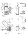
- Figures A and B show a known solution of mammographic apparatus, which illustrates the prior art.
- Figures A and B show a prior-art solution of mammographic apparatus, wherein the part 3 that supports the tube head 2 and the depicting means is mounted at its centre P of gravity on the vertical frame 4 of the apparatus 1.
- the apparatus 1 requires a locking device.
- the apparatus of this prior-art solution causes a necessity both to adjust the height and to shift the patient laterally on moving from one projection C, D, E to the other, which makes the photographing slower and more difficult and prevents automation of the apparatus on moving from one projection to the other.
- the apparatus comprises a vertically displaceable vertical frame 4, to which a part turnable around a horizontal axis b-b is attached, said part comprising the tube head 2 and the press plates 6 and 7 as well as the film holder 3.
- the vertical frame 4 is arranged displaceable in the vertical direction on the frame part 54, said frame part 54 comprising a vertical guide or guides 57.
- a motor 51 is fixed, by means of which the transfer screw 52 is rotated.
- a gas spring 58 is fitted between the frame 4 and the pedescal 55, said gas spring 58 being attached from one of its ends to the displaceable frame 4 by means of a projection part 59, the displaceable frame 4 by means of a projection part 59.
- the part 3 that supports the tube head 2 and the depicting means is mounted on the vertical frame 4 of the apparatus 1 at the central axis a-a of the breast M 1 that is pressed between the upper press member 6 and the lower press member 7.
- the apparatus in accordance with the invention eliminates any necessity to readjust the apparatus or the position of the patient when moving from one projection f,g,h (different positions M 1 , M 2 , and M 3 of the breasts) to the other.
- the apparatus in accordance with the present invention requires particular operations to counterbalance the apparatus (will be described in more detail in relation to Fig. 3), but said particular operations are reasonable in view of the advantage that is achieved.
- the operation of the apparatus is motorized, so that complete counterbalancing is not indispensable or even needed.
- the upper press member 6 is mounted on the rod 10 by means of a linear journalling 9.
- the tip 6' of the downwardly inclined upper press member 6 grasps the breast M 1 at its root J.
- the upper press member 6 is pivoted around its tip 6' at the same time as the upper press member 6 moves in its linear journalling 9 along the guide bar 10 and is pivoted around its articulation point 8.
- the articulation point 8 is provided with an adjustable spring loading, which permits pivoting of the upper press member 6 until it reaches its normal position 6a, i.e. the position parallel to the lower press plate, whereupon the pressing of the breast M 1 can be increased further if necessary while the press member 6a retains its orientation.
- FIG. 3 the apparatus 1 in accordance with the invention is shown in the position after biopsy photography, corresponding to the removal of the film cassette. Thereat the breast M 1 is still pressed between the upper press member 6 and the lower press member 7, but the cassette rack 22 and the tube head 2 have been run slightly downwards by means of the motor 12 and the screw 13 for removal of the cassette 21.
- a revolving part 25 is supported on the vertical frame 4 of the apparatus 1 by means of bearings 30, said part 25 being provided with a stationary lower press plate 7.
- the film holder 22 itself and the tube head 2 are attached to a common frame part 10, which is mounted by means of a linear journalling 23 on the part 25 revolving around the horizontal axis b-b.
- the upper press member 6 moves relative the frame part 10 in its journalling 9, and the lower press member 7 is stationary.
- the vertical frame part 10 is displaced by means of the motor 12 and the screw 13.
- the revolving part 25 comprises a spiral gear 14, to which a spiral screw 15 as well as a primary gear 16 and a rotating motor 17 are connected.
- the movement of rotation is counterbalanced by means of a balancing gas spring 18, one of whose ends is connected to the wheel 14 by means of a lever, while the other end is connected to the vertical frame 4 of the apparatus 1 by means of an arm 18a.
- the rotation of the part 25 also takes place around the central axis a-a of the breast M, because the central axis a-a substantially coincides with the axis b-b of rotation of the part 25.
- the apparatus 1 in accordance with the invention includes readiness for biopsy photography, so that separate installation of an additional part is not necessary when moving over to biopsy photography; only the upper press plate 6 must be exchanged.
- the upper press plate 6 is chosen in accordance with the film size used. The film sizes may be, e.g., 18 x 24 cm or 24 x 30 cm. Different types of upper press plates 6 of different sizes are needed for the apparatus 1 in accordance with the invention, for both film sizes, the plates needed for biopsy photography, as well as the spot photography plates.
- the upper press plates 6 are made of a material readily penetrable by X-radiation most appropriately, e.g., so that the transparent part is made of polycarbonate or acrylic and connected to the width-adjustment unit shown in Fig. 9. In this way the press plates can be made simple and inexpensive.
- Fig. 4 shows the shields used in the device 1 in accordance with the invention.
- the upper shield 26 is linked 27 with the upper press member 6 and attached by means of its guide groove 28 to the tube head 2.
- the lower shield curtain 29 is attached to the part 3 that supports the depicting means and to the lower press member 7.
- the upper shield 26 protects the head and jaw and the shoulders of the person to be photographed as well as, in the case of fat persons, any extra fatty tissue from the radiation beam R.
- the lower shield curtain is needed mainly only in enlarged photography to prevent access of fatty tissue of the person to be photographed between the lower press member 6 and the part 3 that supports the depicting means.
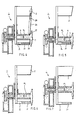
- Fig. 5 shows the apparatus 1 in accordance with the invention in the normal photographing position.
- the lower press plate 7 has been run into contact with the part 3 that supports the depicting means 21. From normal photography it is possible to move over to enlarged photography and to biopsy photography without removing the breast M 1 (from between the upper press member 6 and the lower press member 7).
- Fig. 6 shows the apparatus in accordance with the invention in the biopsy photography position.
- Fig. 7 shows the apparatus 1 in accordance with the invention in enlarged photography.
- the ratio of enlargement can be chosen freely.
- the ratio of enlargement in enlarged photography is 1.5:1, but in the solution in accordance with the invention the ratio of enlargement can be chosen and adjusted continuously.
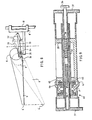
- Fig. 8 is a schematical illustration of the mechanism of articulation of the upper press member 6, which said mechanism permits the upper press member 6 to grasp the breast M at its root in accordance with what is explained in connection with Fig. 2, thereby leaving space for the hands of the nurse to "stretch" the breast at the initial stage of the pressing.
- the pressing can be continued in the same way as in prior-art solutions.
- its tip 6' remains on the vertical line denoted with a dotted-dashed line in Fig. 8.
- the part denoted with the reference numeral 9' is a sledge that can move in the direction of pressing and that belongs to the mechanism.
- the parts of the articulation mechanism of the press member 6 also include a lever 32, which is connected to the casing 34 of the linear bearing by the intermediate of the rod 33, said casing being, e.g., a cross-piece, whose articulation pins are, in Fig. 8, denoted with the reference numeral 35.
- an adjustable spring 31 the force is determined that is opposed to the pivoting of the press member to the horizontal position, i.e. the force with which the tip 6' of the press member presses the breast.
- Fig. 9 illustrates the width-adjustment mechanism of the exchangeable press plates 6, which said mechanism is provided with an emergency-release torque switch.
- the width-adjustment wheel 36 is in direct contact with the holders, e.g. brackets 37, to which the press plates 6 are attached. Between the shaft 42 and the brackets 37, there are parts 38 which permit only axial movement.
- the frame 39 of the width-adjustment mechanism is attached to the rods 33 shown in Fig. 8.
- the shaft 42 is locked non-revolving in the frame part by means of the torque switch 40, which is provided, e.g., with such a torque-adjustment wheel as is provided with recesses 46 in which the pins 45 provided on the frame part are locked when the wheel is tightened.
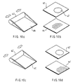
- Figures 10a...10d show different press plates.
- Fig. 10a shows a press plate 6A, e.g., for a photographing press member of a size of 30 x 24 cm.
- the press plate can be placed into a regulating mechanism 42 which can be adjusted for different widths.
- the "spot" photographing press plate 6B which is provided with an opening 47, is denoted with the numeral 43, and the biopsy press plate with the numeral 44.
- Figs. 10c and 10d with reference numerals 42', 43',44', reference is made to the same parts as in Figs. 10a and 10b, but for smaller, e.g. 24 x 18 cm, photographing press members 6C.
Abstract
Description
- The invention starts out from a mammographic apparatus as disclosed in the document US-A-3,609,355 which forms the closest prior art.
- In general mammography means a method of radioscopy of breasts, wherein a roentgenogram is taken of the breasts. In connection with the photographing, the breast is pressed and spread in a way known in prior art between the holders in the photographing apparatus.
- Owing to the nature of the tissue to be photographed, in the photography a soft radiation is used, the anode voltage of the X-ray tube being about 20...28 kV. This results in problems of scattering, which are the more important, the thicker the tissue to be photographed is. In mammography, it would, however, be important also to depict so-called microcalcifications, whose diameters are of an order of 0.1 mm.
- As is known in prior art, in complete mammographic photography, three different projections are used. In mass photography, only one, as a rule vertical, projection is used.
- In addition to the roentgenograms taken in different projections, if necessary, enlarged photographs are taken of suspected locations.
- Prior-art apparatuses can also be used for so-called biopsy photographing. Biopsy photography means a method wherein the breast is photographed by using a so-called biopsy plate so that the openings in the biopsy plate become visible in the roentgenogram. In biopsy photography, the film is developed while the breast to be photographed is kept in its holders, and the finding, if any, is located with the aid of the holes in the biopsy plate, and with their aid a sample is taken from a suspected location.
- By means of prior-art mammographic apparatuses, it is also possible to take enlarged roentgenograms, which takes place so that a particular stand is placed on the normal breast holder, by means of which said stand the breast to be photographed is placed closer to the focus of the source of radiation. The use of such a separate stand is inconvenient, and, thus, one object of the present invention is to provide a new apparatus, wherein said separate stand becomes unnecessary.
- In mammography, attempts are made to press the breast as flat as possible, because soft secondary radiation is scattered. The thinner the breast can be made, the less secondary radiation can be scattered. To prevent scattering, lattice solutions of various types are also used.
- In respect of further prior art related to the present invention, reference is made by way of example to the mammographic apparatuses known from the following US Patents: 3,824,297, 3,971,950, 4,097,748, 4,599,738, and 4,613,982.
- The prior-art mammographic apparatuses have involved several drawbacks, which are supposed to be eliminated in certain respects by means of the new solutions of the present invention.
- One of the most important drawbacks has consisted of the difficulties in the operation of the prior-art apparatuses, said difficulties including the necessity of the patient to move and to change her place when the projection or mode of photographing is changed, and it has been necessary to adjust the level of the breast holders in the apparatus between different processes of photography. This has increased the time taken by the photography, which is a considerable drawback in particular in the case of mass photography.
- In the prior-art apparatuses, difficulties have also occurred in how to be able to press and to attach the breast to be photographed between the holders in the apparatus in a favourable way. The stage of pressing the breast, which is included in mammography, is often experienced by the patients as quite disagreeable, and as this stage has, in the prior-art apparatuses, often been associated with a necessity to readjust the breast to be photographed in a more advantageous position, said drawback has been experienced as quite embarrassing.
- Thus, an object of the invention is to provide a mammographic apparatus in which the various roentgenograms can be taken without having to shift the patient or to adjust the level of the apparatus when moving from one projection or mode of photography to the other.
- This object is solved by an apparatus comprising the features of the
patent claim 1. - In the following, the invention will be described in detail with reference to the figures in the accompanying drawing while starting from a prior-art solution.
- Figures A and B show a known solution of mammographic apparatus, which illustrates the prior art.
- Figure 1 is a schematical side view of an apparatus in accordance with the invention as a whole.
- Figures 1a and 1b are schematical illustrations of a solution of mammographic equipment from two different projections.
- Figure 2 is a schematical illustration of the shifting of the upper press member into its position in accordance with the invention.
- Figure 3 is a schematical illustration of a mammographic apparatus in accordance with the invention in the situation of removal of the cassette after biopsy photography.
- Figure 4 illustrates the shields used in a mammographic apparatus in accordance with the invention.
- Figure 5 is a schematical illustration of a mammographic apparatus in accordance with the invention in its position of normal photography.
- Figure 6 is a schematical illustration of an apparatus in accordance with the invention in the biopsy photography position.
- Figure 7 shows a mammographic apparatus in accordance with the invention in the position of enlarged photography.
- Figure 8 is a schematical illustration of the tilting mechanism of the upper press member.
- Figure 9 illustrates the width adjustment mechanism of the apparatus.
- Figures 10a..10d illustrate different exchangeable upper press plates.
-
- Figures A and B show a prior-art solution of mammographic apparatus, wherein the
part 3 that supports thetube head 2 and the depicting means is mounted at its centre P of gravity on thevertical frame 4 of theapparatus 1. By means of such an apparatus, the advantage is obtained that theapparatus 1 can be balanced by and large. However, a drawback is that theapparatus 1 requires a locking device. Also, the apparatus of this prior-art solution causes a necessity both to adjust the height and to shift the patient laterally on moving from one projection C, D, E to the other, which makes the photographing slower and more difficult and prevents automation of the apparatus on moving from one projection to the other. - To start with, referring to Fig. 1, the basic construction of the
apparatus 1 in accordance with the invention will be described. The apparatus comprises a vertically displaceablevertical frame 4, to which a part turnable around a horizontal axis b-b is attached, said part comprising thetube head 2 and thepress plates film holder 3. Thevertical frame 4 is arranged displaceable in the vertical direction on theframe part 54, saidframe part 54 comprising a vertical guide orguides 57. In connection with thevertical guides 57 there areglide casings 56a and 56b, which are fitted around thevertical guides 57. In connection with thepedestal 55 of the apparatus, amotor 51 is fixed, by means of which thetransfer screw 52 is rotated. In connection with the threading of thetransfer screw 52 there is a threadedpart 53, by whose means theframe 4 is displaced vertically. In view of compensating for the weight of thedisplaceable frame 4 and of the other parts attached to same, agas spring 58 is fitted between theframe 4 and thepedescal 55, saidgas spring 58 being attached from one of its ends to thedisplaceable frame 4 by means of a projection part 59, thedisplaceable frame 4 by means of a projection part 59. - In the
apparatus 1 in accordance with Figures 1a and 1b, thepart 3 that supports thetube head 2 and the depicting means is mounted on thevertical frame 4 of theapparatus 1 at the central axis a-a of the breast M1 that is pressed between theupper press member 6 and thelower press member 7. Thereby the apparatus in accordance with the invention eliminates any necessity to readjust the apparatus or the position of the patient when moving from one projection f,g,h (different positions M1, M2, and M3 of the breasts) to the other. The apparatus in accordance with the present invention, however, requires particular operations to counterbalance the apparatus (will be described in more detail in relation to Fig. 3), but said particular operations are reasonable in view of the advantage that is achieved. Moreover, the operation of the apparatus is motorized, so that complete counterbalancing is not indispensable or even needed. Thus, by means of the apparatus of the invention, it is possible to increase the degree of automation. - In mammography, it is critical that the commonest location of cancer is in the outer upper quarter of the breast close to the body. Thus, it is important that the tissue at the root of the breast is included in the picture. When prior-art apparatuses are used, the nurse spreads the breast from the rear at the initial stage of the pressing of the breast, and thereat, when the upper press member approaches the breast, there remains no space for the hands of the nurse, and she must release her grasp before the press member locks the breast. On the contrary, in the upper press-member solution in accordance with the invention, which is shown in Fig. 2, there remains space for the hands of the nurse to spread the breast on the
lower press member 7 at the initial stage of the pressing, the tip 6' of thepress member 6 locking the press at the end of said initial stage. Theupper press member 6 is mounted on therod 10 by means of alinear journalling 9. Thus, the tip 6' of the downwardly inclinedupper press member 6 grasps the breast M1 at its root J. whereinafter theupper press member 6 is pivoted around its tip 6' at the same time as theupper press member 6 moves in itslinear journalling 9 along theguide bar 10 and is pivoted around itsarticulation point 8. Thearticulation point 8 is provided with an adjustable spring loading, which permits pivoting of theupper press member 6 until it reaches itsnormal position 6a, i.e. the position parallel to the lower press plate, whereupon the pressing of the breast M1 can be increased further if necessary while thepress member 6a retains its orientation. - In Fig. 3, the
apparatus 1 in accordance with the invention is shown in the position after biopsy photography, corresponding to the removal of the film cassette. Thereat the breast M1 is still pressed between theupper press member 6 and thelower press member 7, but thecassette rack 22 and thetube head 2 have been run slightly downwards by means of themotor 12 and thescrew 13 for removal of thecassette 21. - In Figures 2 and 3, a revolving
part 25 is supported on thevertical frame 4 of theapparatus 1 by means ofbearings 30, saidpart 25 being provided with a stationarylower press plate 7. The film holder 22 itself and thetube head 2 are attached to acommon frame part 10, which is mounted by means of alinear journalling 23 on thepart 25 revolving around the horizontal axis b-b. In Fig. 3, theupper press member 6 moves relative theframe part 10 in itsjournalling 9, and thelower press member 7 is stationary. Thus, without any separate additional part, it is possible to move over to enlarged photography, even without releasing the pressing. Moreover, by means of the solution in accordance with the invention, it is possible to substitute for a biopsy cassette rack. - The
vertical frame part 10 is displaced by means of themotor 12 and thescrew 13. The revolvingpart 25 comprises aspiral gear 14, to which a spiral screw 15 as well as a primary gear 16 and a rotating motor 17 are connected. The movement of rotation is counterbalanced by means of a balancinggas spring 18, one of whose ends is connected to thewheel 14 by means of a lever, while the other end is connected to thevertical frame 4 of theapparatus 1 by means of anarm 18a. When moving over to a new projection g,h of photography, the rotation of thepart 25 also takes place around the central axis a-a of the breast M, because the central axis a-a substantially coincides with the axis b-b of rotation of thepart 25. Thus, when the projection of photography is being changed, the necessity of height adjustment of theapparatus 1 is eliminated. - The
apparatus 1 in accordance with the invention includes readiness for biopsy photography, so that separate installation of an additional part is not necessary when moving over to biopsy photography; only theupper press plate 6 must be exchanged. Theupper press plate 6 is chosen in accordance with the film size used. The film sizes may be, e.g., 18 x 24 cm or 24 x 30 cm. Different types ofupper press plates 6 of different sizes are needed for theapparatus 1 in accordance with the invention, for both film sizes, the plates needed for biopsy photography, as well as the spot photography plates. Theupper press plates 6 are made of a material readily penetrable by X-radiation most appropriately, e.g., so that the transparent part is made of polycarbonate or acrylic and connected to the width-adjustment unit shown in Fig. 9. In this way the press plates can be made simple and inexpensive. - Fig. 4 shows the shields used in the
device 1 in accordance with the invention. Theupper shield 26 is linked 27 with theupper press member 6 and attached by means of itsguide groove 28 to thetube head 2. Thelower shield curtain 29 is attached to thepart 3 that supports the depicting means and to thelower press member 7. Theupper shield 26 protects the head and jaw and the shoulders of the person to be photographed as well as, in the case of fat persons, any extra fatty tissue from the radiation beam R. The lower shield curtain is needed mainly only in enlarged photography to prevent access of fatty tissue of the person to be photographed between thelower press member 6 and thepart 3 that supports the depicting means. - Fig. 5 shows the
apparatus 1 in accordance with the invention in the normal photographing position. In such a case, thelower press plate 7 has been run into contact with thepart 3 that supports the depictingmeans 21. From normal photography it is possible to move over to enlarged photography and to biopsy photography without removing the breast M1 (from between theupper press member 6 and the lower press member 7). - Fig. 6 shows the apparatus in accordance with the invention in the biopsy photography position.
- Fig. 7 shows the
apparatus 1 in accordance with the invention in enlarged photography. In theapparatus 1 of the invention, the ratio of enlargement can be chosen freely. Typically, the ratio of enlargement in enlarged photography is 1.5:1, but in the solution in accordance with the invention the ratio of enlargement can be chosen and adjusted continuously. - Fig. 8 is a schematical illustration of the mechanism of articulation of the
upper press member 6, which said mechanism permits theupper press member 6 to grasp the breast M at its root in accordance with what is explained in connection with Fig. 2, thereby leaving space for the hands of the nurse to "stretch" the breast at the initial stage of the pressing. After theupper press member 6 has pivoted against the load of theadjustable spring 31 to the normal position, i.e. substantially parallel to the lower press plate, the pressing can be continued in the same way as in prior-art solutions. During the pivoting movement of thepress member 6, its tip 6' remains on the vertical line denoted with a dotted-dashed line in Fig. 8. The part denoted with the reference numeral 9' is a sledge that can move in the direction of pressing and that belongs to the mechanism. The parts of the articulation mechanism of thepress member 6 also include alever 32, which is connected to thecasing 34 of the linear bearing by the intermediate of therod 33, said casing being, e.g., a cross-piece, whose articulation pins are, in Fig. 8, denoted with thereference numeral 35. By means of anadjustable spring 31, the force is determined that is opposed to the pivoting of the press member to the horizontal position, i.e. the force with which the tip 6' of the press member presses the breast. - Fig. 9 illustrates the width-adjustment mechanism of the
exchangeable press plates 6, which said mechanism is provided with an emergency-release torque switch. The width-adjustment wheel 36 is in direct contact with the holders,e.g. brackets 37, to which thepress plates 6 are attached. Between theshaft 42 and thebrackets 37, there areparts 38 which permit only axial movement. Theframe 39 of the width-adjustment mechanism is attached to therods 33 shown in Fig. 8. Theshaft 42 is locked non-revolving in the frame part by means of thetorque switch 40, which is provided, e.g., with such a torque-adjustment wheel as is provided withrecesses 46 in which thepins 45 provided on the frame part are locked when the wheel is tightened. Figures 10a...10d show different press plates. Fig. 10a shows apress plate 6A, e.g., for a photographing press member of a size of 30 x 24 cm. The press plate can be placed into aregulating mechanism 42 which can be adjusted for different widths. In Fig. 10b, the "spot" photographing press plate 6B, which is provided with anopening 47, is denoted with the numeral 43, and the biopsy press plate with the numeral 44. In Figs. 10c and 10d, with reference numerals 42', 43',44', reference is made to the same parts as in Figs. 10a and 10b, but for smaller, e.g. 24 x 18 cm, photographingpress members 6C. - As has come out above, in the invention it is possible to use simple and inexpensive press plates in connection with a
common mechanism 42 adjustable for different widths. Thereby substantial economies are obtained as compared with the fact that in prior art, as a rule, six different upper press members were required. - It is to be emphasized strongly that above only some exemplifying embodiments of the invention have been described, and the scope of the invention also includes numerous modifications of the apparatuses of the invention which are obvious for a person skilled in the art, of which only the following should be mentioned in this connection. The apparatuses of the invention can also be applied in such mammography in which no X-ray film is used but in which the picture is reproduced by means of detectors which are sensitive to radiation and in themselves known, e.g. by means of electric detectors, from which an electric signal is obtained, on whose basis the picture is stored on storage media in themselves known. The definition 'film cassette or equivalent' used in the application includes such means for reproduction and storage of a picture. The scope of the invention also includes such modifications of the apparatus as have no separate lower breast holder at all but in which the film cassette or parts placed in its connection or any other, corresponding picture reproduction means referred to above act as the lower holder.
Claims (5)
- Mammographic apparatus, comprising a frame part (4), on which a turnable frame part (25) is mounted (30), most approximately as turnable around a horizontal axis (b-b), and in which said frame part (25) a source (2) of radiation and means for holding the film cassette (21) as well as holders (6, 7) for the breast to be photographed, to be placed between the source (2) of radiation and said cassette supporting means, are fitted, which said breast holders comprise a lower holder (7) and an upper holder (6), which are displaceable relative one another so as to press the breast (M) to be photographed between said holders (6, 7), characterized in that the lower holder (7) of the breast is fitted in connection with said turnable frame part (25), most appropriately as fixed, and that said lower holder (7) is placed in such a position relative the axis (b-b) of rotation of the turnable frame part (25) that, when the breast (M) to be photographed is pressed from above by means of the displaceable upper holder (6), the central axis (a-a) of the breast substantially coincides with the axis (b-b) of rotation of the turnable frame part (25) wherein the rotation of the turnable frame part (25) of the apparatus is motorized for counterbalancing the apparatus.
- Mammographic apparatus as claimed in claim 1, characterized in that the upper holder (6) is attached non-pivotably to a guide part (9), which is fitted in such a guide in which the source (2) of radiation is fitted as stationary at one side of the press members (6, 7) and in which the part (3) that supports the depicting means is fitted as stationary at the other side of the press members (6, 7), and that between the lower holder (7), which is attached stationarily to the rotatable frame part (25), and the upper holder (6), which is placed facing the lower holder, a transfer device is provided, most appropriately a transfer screw (20) driven by a motor (19), by means of which said transfer screw (20) the upper holder (6) can be displaced in its guide (9, 10) relative said lower holder (7) so as to press the breast (M) to be photographed between said holders (6, 7).
- Mammographic apparatus as claimed in any of the claims 1 and 2, characterized in that said rotatable frame part (25) comprises a vertical part, which is provided with guides (23), in connection with which there is a guide-frame part (10), the source (2) of radiation being attached to one end of said guide-frame part (10) and the support-frame part (3) for the depicting means (21) being attached to the other end of said guide-frame part (10), and that between said guide-frame part (10) and the rotatable frame part (25), transfer means are provided, preferably a motor and a transfer screw (13), by means of which the source (2) of radiation and the part (3) that supports the depicting means (21) can be shifted as one unit relative said frame part (25) and relative the press member (7) or press members (6, 7) that press the breast (M) to be photographed.
- Mammographic apparatus as claimed in any of the claims 1 to 3, characterized in that said rotatable frame part (25) comprises a horizontal shaft which is supported by bearings (30) on the vertical frame part (4) of the apparatus, that said shaft is provided with a drive wheel (14), which is driven by a motor, most appropriately a screw motor, by the intermediate of the toothing on its outer rim, and that to said wheel (14) a gas spring device (18) is attached that substantially balances the rotatable frame part (25) and the various parts attached to same during change of projection of photography.
- Mammographic apparatus as claimed in any of the claims 1 to 4, characterized in that the apparatus comprises a frame part (25) turnable around a substantially horizontal axis and mounted on a vertically displaceable frame (4), that said displaceable frame (4) is arranged to be displaceable by a motor, most appropriately a screw motor (51, 52), in the vertical direction on guider (56a, 56b, 57), and that, to compensate for the weight of the displaceable frame (4) and of the other parts attached to said frame, a gas spring (58) or an equivalent compensation member is provided (Fig. 1).
Priority Applications (2)
| Application Number | Priority Date | Filing Date | Title |
|---|---|---|---|
| AT89905117T ATE102461T1 (en) | 1988-05-26 | 1989-05-04 | MAMMOGRAPHIC METHODS AND DEVICES. |
| EP93102302A EP0543801B1 (en) | 1988-05-26 | 1989-05-04 | Mammographic apparatuses |
Applications Claiming Priority (3)
| Application Number | Priority Date | Filing Date | Title |
|---|---|---|---|
| FI882490A FI80996C (en) | 1988-05-26 | 1988-05-26 | Mammography method and apparatus |
| FI882490 | 1988-05-26 | ||
| PCT/FI1989/000082 WO1989011248A1 (en) | 1988-05-26 | 1989-05-04 | Mammographic methods and apparatuses |
Related Child Applications (2)
| Application Number | Title | Priority Date | Filing Date |
|---|---|---|---|
| EP93102302A Division EP0543801B1 (en) | 1988-05-26 | 1989-05-04 | Mammographic apparatuses |
| EP93102302.2 Division-Into | 1993-02-13 |
Publications (3)
| Publication Number | Publication Date |
|---|---|
| EP0370089A1 EP0370089A1 (en) | 1990-05-30 |
| EP0370089B1 EP0370089B1 (en) | 1994-03-09 |
| EP0370089B2 true EP0370089B2 (en) | 2004-04-14 |
Family
ID=8526526
Family Applications (2)
| Application Number | Title | Priority Date | Filing Date |
|---|---|---|---|
| EP89905117A Expired - Lifetime EP0370089B2 (en) | 1988-05-26 | 1989-05-04 | Mammographic apparatuses |
| EP93102302A Expired - Lifetime EP0543801B1 (en) | 1988-05-26 | 1989-05-04 | Mammographic apparatuses |
Family Applications After (1)
| Application Number | Title | Priority Date | Filing Date |
|---|---|---|---|
| EP93102302A Expired - Lifetime EP0543801B1 (en) | 1988-05-26 | 1989-05-04 | Mammographic apparatuses |
Country Status (7)
| Country | Link |
|---|---|
| US (1) | US5050197A (en) |
| EP (2) | EP0370089B2 (en) |
| JP (1) | JP2672383B2 (en) |
| AT (1) | ATE169201T1 (en) |
| DE (2) | DE68913662T3 (en) |
| FI (1) | FI80996C (en) |
| WO (1) | WO1989011248A1 (en) |
Families Citing this family (36)
| Publication number | Priority date | Publication date | Assignee | Title |
|---|---|---|---|---|
| FI85803C (en) * | 1989-11-23 | 1992-06-10 | Planmed Oy | FOERFARANDE OCH ANORDNING FOER STYRNING AV FUNKTIONER AV EN MAMMOGRAFIROENTGENANORDNING. |
| US6031892A (en) | 1989-12-05 | 2000-02-29 | University Of Massachusetts Medical Center | System for quantitative radiographic imaging |
| SE9100362L (en) * | 1991-02-05 | 1992-02-03 | Siemens Elema Ab | RADIO SURVEY APPARATUS FOR BROEST SURVEYS |
| US5289520A (en) * | 1991-11-27 | 1994-02-22 | Lorad Corporation | Stereotactic mammography imaging system with prone position examination table and CCD camera |
| US5594769A (en) * | 1991-11-27 | 1997-01-14 | Thermotrex Corporation | Method and apparatus for obtaining stereotactic mammographic guided needle breast biopsies |
| FR2697741B1 (en) * | 1992-11-10 | 1995-02-03 | Gen Electric Cgr | Compression device for radiological device. |
| DE4300796A1 (en) * | 1993-01-14 | 1994-07-21 | Philips Patentverwaltung | X-ray device with a device part that can be pivoted about a horizontal swivel axis |
| JPH07303633A (en) | 1994-05-11 | 1995-11-21 | Mitsubishi Electric Corp | X-ray breasts imaging device |
| US5506877A (en) * | 1994-11-23 | 1996-04-09 | The General Hospital Corporation | Mammography breast compression device and method |
| US5706327A (en) * | 1996-02-09 | 1998-01-06 | Trex Medical Corporation | Method and apparatus for mammographic compression |
| US6142667A (en) * | 1998-09-21 | 2000-11-07 | Oec Medical Systems, Inc. | Gas-spring assisted, counter-balanced L-arm assembly for fluoroscopic imaging |
| US6675037B1 (en) * | 1999-09-29 | 2004-01-06 | Regents Of The University Of Minnesota | MRI-guided interventional mammary procedures |
| US6507748B2 (en) * | 1999-12-30 | 2003-01-14 | The Brigham And Women's Hospital, Inc. | Compression apparatus for diagnostically examining breast tissue |
| SE0103474D0 (en) * | 2001-10-18 | 2001-10-18 | Siemens Elema Ab | X-ray diagnostic apparatus for mammography examinations |
| SE0201211D0 (en) | 2002-04-23 | 2002-04-23 | Siemens Elema Ab | X-ray diagnostic apparatus for mammography examinations |
| SE0201806D0 (en) * | 2002-06-13 | 2002-06-13 | Siemens Elema Ab | X-ray diagnostic apparatus for mammography examinations |
| FR2842722B1 (en) * | 2002-07-29 | 2005-03-25 | Ge Med Sys Global Tech Co Llc | SIMPLIFIED COMPRESSION MAMMOGRAPHY |
| US6999553B2 (en) * | 2003-03-04 | 2006-02-14 | Livingston Products, Inc. | Method and apparatus for x-ray mammography imaging |
| DE10353611B4 (en) | 2003-11-17 | 2013-01-17 | Siemens Aktiengesellschaft | X-ray diagnostic device for mammography examinations |
| CN101612047B (en) * | 2004-08-03 | 2013-03-06 | 株式会社东芝 | Image displaying apparatus |
| DE102004052614B3 (en) * | 2004-10-29 | 2006-01-05 | Siemens Ag | Compression plate, in particular for a mammography device |
| US7245694B2 (en) * | 2005-08-15 | 2007-07-17 | Hologic, Inc. | X-ray mammography/tomosynthesis of patient's breast |
| JP4598135B2 (en) * | 2005-10-06 | 2010-12-15 | 富士フイルム株式会社 | Breast imaging device |
| JP4769097B2 (en) * | 2006-03-01 | 2011-09-07 | 富士フイルム株式会社 | Mammography device and breast compression plate used in the mammography device |
| JP4950612B2 (en) | 2006-09-29 | 2012-06-13 | 富士フイルム株式会社 | Mammography apparatus, breast pressing plate, and breast fixing method |
| FI123261B (en) | 2008-11-28 | 2013-01-15 | Planmed Oy | 3D mammography |
| WO2012048000A2 (en) | 2010-10-05 | 2012-04-12 | Hologic, Inc. | Upright x-ray breast imaging with a ct mode, multiple tomosynthesis modes, and a mammography mode |
| JP2012176122A (en) * | 2011-02-25 | 2012-09-13 | Canon Inc | Radiation imaging apparatus and radiation detection system |
| JP5355619B2 (en) * | 2011-04-27 | 2013-11-27 | 富士フイルム株式会社 | Radiation imaging equipment |
| KR102080176B1 (en) * | 2012-03-29 | 2020-02-21 | 제네럴 일렉트릭 컴퍼니 | Mammography apparatus |
| DE102012212136A1 (en) | 2012-07-11 | 2014-01-16 | Siemens Aktiengesellschaft | Device and method for a diagnostic device |
| CN105228526B (en) * | 2013-03-29 | 2018-06-08 | 通用电气公司 | Mammography apparatus |
| WO2014157793A1 (en) * | 2013-03-29 | 2014-10-02 | 주식회사 레이언스 | Mammography device and location arrangement control method thereof |
| ES2954561T3 (en) | 2013-10-09 | 2023-11-23 | Hologic Inc | X-ray breast tomosynthesis that enhances spatial resolution, even in the thickness direction of a flattened breast |
| CN109171779A (en) * | 2018-10-08 | 2019-01-11 | 北京万东医疗科技股份有限公司 | The control method and device of equal centers control arm non-to mammary machine |
| KR102314303B1 (en) | 2019-04-16 | 2021-10-20 | 주식회사 디알텍 | Radiographic apparatus and radiographic method |
Citations (2)
| Publication number | Priority date | Publication date | Assignee | Title |
|---|---|---|---|---|
| US4433690A (en) † | 1981-07-20 | 1984-02-28 | Siemens Ag | Compact ultrasound apparatus for medical examination |
| US4727565A (en) † | 1983-11-14 | 1988-02-23 | Ericson Bjoern E | Method of localization |
Family Cites Families (9)
| Publication number | Priority date | Publication date | Assignee | Title |
|---|---|---|---|---|
| US3609355A (en) * | 1968-05-31 | 1971-09-28 | Schick X Ray Co Inc | X-ray mammograph in which the x-ray source and film cassette are rotatable about the subject being photograph |
| JPS5564265A (en) * | 1978-11-08 | 1980-05-14 | Hitachi Ltd | Recording state judging device |
| DE3319622A1 (en) * | 1983-05-30 | 1984-12-06 | Siemens AG, 1000 Berlin und 8000 München | X-RAY DIAGNOSTICS DEVICE FOR MAMMOGRAPHY IMAGES |
| US4768516A (en) * | 1983-10-14 | 1988-09-06 | Somanetics Corporation | Method and apparatus for in vivo evaluation of tissue composition |
| DE3339775A1 (en) * | 1983-11-03 | 1985-05-15 | Siemens AG, 1000 Berlin und 8000 München | X-RAY DIAGNOSTIC DEVICE WITH RADIATION FILTERS |
| DE8332063U1 (en) * | 1983-11-08 | 1984-01-05 | Siemens AG, 1000 Berlin und 8000 München | X-ray diagnostic device with a compression trolley |
| US4599738A (en) * | 1984-04-17 | 1986-07-08 | Patrick Panetta | Universal mammography compression system |
| JPH074354B2 (en) * | 1984-10-29 | 1995-01-25 | 富士写真フイルム株式会社 | Radiation image information recording / reading device |
| JPS61170441A (en) * | 1985-01-23 | 1986-08-01 | 横河メディカルシステム株式会社 | Gantry of radiation tomographic apparatus |
-
1988
- 1988-05-26 FI FI882490A patent/FI80996C/en not_active IP Right Cessation
-
1989
- 1989-05-04 EP EP89905117A patent/EP0370089B2/en not_active Expired - Lifetime
- 1989-05-04 AT AT93102302T patent/ATE169201T1/en not_active IP Right Cessation
- 1989-05-04 US US07/438,460 patent/US5050197A/en not_active Expired - Lifetime
- 1989-05-04 DE DE68913662T patent/DE68913662T3/en not_active Expired - Lifetime
- 1989-05-04 WO PCT/FI1989/000082 patent/WO1989011248A1/en active IP Right Grant
- 1989-05-04 EP EP93102302A patent/EP0543801B1/en not_active Expired - Lifetime
- 1989-05-04 JP JP1504518A patent/JP2672383B2/en not_active Expired - Lifetime
- 1989-05-04 DE DE68928770T patent/DE68928770T2/en not_active Expired - Fee Related
Patent Citations (2)
| Publication number | Priority date | Publication date | Assignee | Title |
|---|---|---|---|---|
| US4433690A (en) † | 1981-07-20 | 1984-02-28 | Siemens Ag | Compact ultrasound apparatus for medical examination |
| US4727565A (en) † | 1983-11-14 | 1988-02-23 | Ericson Bjoern E | Method of localization |
Also Published As
| Publication number | Publication date |
|---|---|
| FI882490A (en) | 1989-11-27 |
| EP0543801A2 (en) | 1993-05-26 |
| FI80996B (en) | 1990-05-31 |
| WO1989011248A1 (en) | 1989-11-30 |
| DE68913662T3 (en) | 2004-10-07 |
| EP0370089B1 (en) | 1994-03-09 |
| EP0543801B1 (en) | 1998-08-05 |
| JP2672383B2 (en) | 1997-11-05 |
| DE68928770D1 (en) | 1998-09-10 |
| FI80996C (en) | 1991-10-25 |
| DE68928770T2 (en) | 1998-12-10 |
| EP0543801A3 (en) | 1993-08-11 |
| JPH02504353A (en) | 1990-12-13 |
| ATE169201T1 (en) | 1998-08-15 |
| DE68913662D1 (en) | 1994-04-14 |
| US5050197A (en) | 1991-09-17 |
| FI882490A0 (en) | 1988-05-26 |
| EP0370089A1 (en) | 1990-05-30 |
| DE68913662T2 (en) | 1994-07-07 |
Similar Documents
| Publication | Publication Date | Title |
|---|---|---|
| EP0370089B2 (en) | Mammographic apparatuses | |
| JP3946832B2 (en) | Inspection table | |
| CA1058334A (en) | Independent compression and positioning device for use in mammography | |
| US20090245460A1 (en) | Mammography System And Method Employing Offset Compression Paddles, Automatic Collimation, And Retractable Anti-scatter Grid | |
| US4979196A (en) | Mammograph | |
| US3908126A (en) | X-ray apparatus for providing panoramic radiographic projections | |
| JP2006231054A (en) | Imaging apparatus having protection screen | |
| WO1988004518A1 (en) | Mobile radiography alignment device | |
| JP3028330U (en) | Dental x-ray diagnostic device | |
| US3708664A (en) | Diagnostic x-ray system | |
| US5224140A (en) | Method and apparatus for panoramic radiography | |
| EP0734641B1 (en) | Portable medical panoramic radiographic device | |
| US4339825A (en) | Bi-plane angiographic apparatus | |
| US3030508A (en) | X-ray apparatus | |
| JPH07275240A (en) | Radiographing device for medical treatment | |
| SE9101216D0 (en) | X-ray diagnostic apparatus for mammogram examinations | |
| JPS59151945A (en) | X-ray table apparatus for tomography having false fulcrum point arm pivot shaft | |
| US4455671A (en) | X-Ray cassette holder | |
| FI82368B (en) | Mammography method and equipment | |
| US3930164A (en) | Device for use with X-ray machines | |
| SE455568B (en) | SET AND PLANT FOR X-ray PHOTOGRAPHY OR EQUIVALENT USING AN EXCELLENT PATIENT TABLE | |
| US4321472A (en) | Panoramic dental X-ray machine with camera detached therefrom | |
| JPH07275239A (en) | Patient head fixing device | |
| US2679442A (en) | Serialographic attachment for X-ray examination tables | |
| CN215297837U (en) | Piece device is read with adjustable image to surgery |
Legal Events
| Date | Code | Title | Description |
|---|---|---|---|
| PUAI | Public reference made under article 153(3) epc to a published international application that has entered the european phase |
Free format text: ORIGINAL CODE: 0009012 |
|
| 17P | Request for examination filed |
Effective date: 19891221 |
|
| AK | Designated contracting states |
Kind code of ref document: A1 Designated state(s): AT BE CH DE FR GB IT LI LU NL SE |
|
| 17Q | First examination report despatched |
Effective date: 19921029 |
|
| GRAA | (expected) grant |
Free format text: ORIGINAL CODE: 0009210 |
|
| AK | Designated contracting states |
Kind code of ref document: B1 Designated state(s): AT BE CH DE FR GB IT LI LU NL SE |
|
| PG25 | Lapsed in a contracting state [announced via postgrant information from national office to epo] |
Ref country code: BE Effective date: 19940309 Ref country code: AT Effective date: 19940309 Ref country code: LI Effective date: 19940309 Ref country code: CH Effective date: 19940309 Ref country code: SE Free format text: LAPSE BECAUSE OF FAILURE TO SUBMIT A TRANSLATION OF THE DESCRIPTION OR TO PAY THE FEE WITHIN THE PRESCRIBED TIME-LIMIT Effective date: 19940309 Ref country code: NL Effective date: 19940309 |
|
| REF | Corresponds to: |
Ref document number: 102461 Country of ref document: AT Date of ref document: 19940315 Kind code of ref document: T |
|
| REF | Corresponds to: |
Ref document number: 68913662 Country of ref document: DE Date of ref document: 19940414 |
|
| ITF | It: translation for a ep patent filed |
Owner name: ST. CONSUL.BREVETTUALE S.R.L. |
|
| PG25 | Lapsed in a contracting state [announced via postgrant information from national office to epo] |
Ref country code: LU Free format text: LAPSE BECAUSE OF NON-PAYMENT OF DUE FEES Effective date: 19940531 |
|
| REG | Reference to a national code |
Ref country code: CH Ref legal event code: PL |
|
| ET | Fr: translation filed | ||
| NLV1 | Nl: lapsed or annulled due to failure to fulfill the requirements of art. 29p and 29m of the patents act | ||
| PLBI | Opposition filed |
Free format text: ORIGINAL CODE: 0009260 |
|
| 26 | Opposition filed |
Opponent name: SIEMENS - ELEMA AB Effective date: 19941115 Opponent name: INSTRUMENTARIUM IMAGING Effective date: 19941111 |
|
| PGFP | Annual fee paid to national office [announced via postgrant information from national office to epo] |
Ref country code: GB Payment date: 19980427 Year of fee payment: 10 |
|
| PG25 | Lapsed in a contracting state [announced via postgrant information from national office to epo] |
Ref country code: GB Free format text: LAPSE BECAUSE OF NON-PAYMENT OF DUE FEES Effective date: 19990504 |
|
| GBPC | Gb: european patent ceased through non-payment of renewal fee |
Effective date: 19990504 |
|
| RDAH | Patent revoked |
Free format text: ORIGINAL CODE: EPIDOS REVO |
|
| APAC | Appeal dossier modified |
Free format text: ORIGINAL CODE: EPIDOS NOAPO |
|
| APAE | Appeal reference modified |
Free format text: ORIGINAL CODE: EPIDOS REFNO |
|
| APAC | Appeal dossier modified |
Free format text: ORIGINAL CODE: EPIDOS NOAPO |
|
| PLBQ | Unpublished change to opponent data |
Free format text: ORIGINAL CODE: EPIDOS OPPO |
|
| RAP2 | Party data changed (patent owner data changed or rights of a patent transferred) |
Owner name: PLANMED OY |
|
| PLAB | Opposition data, opponent's data or that of the opponent's representative modified |
Free format text: ORIGINAL CODE: 0009299OPPO |
|
| R26 | Opposition filed (corrected) |
Opponent name: INSTRUMENTARIUM IMAGING * 19941115 SIEMENS - ELEMA Effective date: 19941111 |
|
| PLBQ | Unpublished change to opponent data |
Free format text: ORIGINAL CODE: EPIDOS OPPO |
|
| PLAB | Opposition data, opponent's data or that of the opponent's representative modified |
Free format text: ORIGINAL CODE: 0009299OPPO |
|
| APBU | Appeal procedure closed |
Free format text: ORIGINAL CODE: EPIDOSNNOA9O |
|
| R26 | Opposition filed (corrected) |
Opponent name: INSTRUMENTARIUM IMAGING Effective date: 19941111 Opponent name: SIEMENS - ELEMA AB Effective date: 19941115 |
|
| RTI2 | Title (correction) |
Free format text: MAMMOGRAPHIC APPARATUSES |
|
| PUAH | Patent maintained in amended form |
Free format text: ORIGINAL CODE: 0009272 |
|
| STAA | Information on the status of an ep patent application or granted ep patent |
Free format text: STATUS: PATENT MAINTAINED AS AMENDED |
|
| 27A | Patent maintained in amended form |
Effective date: 20040414 |
|
| AK | Designated contracting states |
Kind code of ref document: B2 Designated state(s): AT BE CH DE FR GB IT LI LU NL SE |
|
| ET3 | Fr: translation filed ** decision concerning opposition | ||
| APAH | Appeal reference modified |
Free format text: ORIGINAL CODE: EPIDOSCREFNO |
|
| PGFP | Annual fee paid to national office [announced via postgrant information from national office to epo] |
Ref country code: DE Payment date: 20080514 Year of fee payment: 20 |
|
| PGFP | Annual fee paid to national office [announced via postgrant information from national office to epo] |
Ref country code: IT Payment date: 20080520 Year of fee payment: 20 |
|
| PGFP | Annual fee paid to national office [announced via postgrant information from national office to epo] |
Ref country code: FR Payment date: 20080430 Year of fee payment: 20 |