EP0361314A2 - Guiding catheter with controllable distal tip - Google Patents
Guiding catheter with controllable distal tip Download PDFInfo
- Publication number
- EP0361314A2 EP0361314A2 EP89117474A EP89117474A EP0361314A2 EP 0361314 A2 EP0361314 A2 EP 0361314A2 EP 89117474 A EP89117474 A EP 89117474A EP 89117474 A EP89117474 A EP 89117474A EP 0361314 A2 EP0361314 A2 EP 0361314A2
- Authority
- EP
- European Patent Office
- Prior art keywords
- catheter
- lumen
- guiding catheter
- wire
- distal
- Prior art date
- Legal status (The legal status is an assumption and is not a legal conclusion. Google has not performed a legal analysis and makes no representation as to the accuracy of the status listed.)
- Granted
Links
Images

Classifications
-
- A—HUMAN NECESSITIES
- A61—MEDICAL OR VETERINARY SCIENCE; HYGIENE
- A61M—DEVICES FOR INTRODUCING MEDIA INTO, OR ONTO, THE BODY; DEVICES FOR TRANSDUCING BODY MEDIA OR FOR TAKING MEDIA FROM THE BODY; DEVICES FOR PRODUCING OR ENDING SLEEP OR STUPOR
- A61M25/00—Catheters; Hollow probes
- A61M25/01—Introducing, guiding, advancing, emplacing or holding catheters
- A61M25/0105—Steering means as part of the catheter or advancing means; Markers for positioning
- A61M25/0133—Tip steering devices
- A61M25/0147—Tip steering devices with movable mechanical means, e.g. pull wires
-
- A—HUMAN NECESSITIES
- A61—MEDICAL OR VETERINARY SCIENCE; HYGIENE
- A61M—DEVICES FOR INTRODUCING MEDIA INTO, OR ONTO, THE BODY; DEVICES FOR TRANSDUCING BODY MEDIA OR FOR TAKING MEDIA FROM THE BODY; DEVICES FOR PRODUCING OR ENDING SLEEP OR STUPOR
- A61M25/00—Catheters; Hollow probes
- A61M25/01—Introducing, guiding, advancing, emplacing or holding catheters
- A61M25/0105—Steering means as part of the catheter or advancing means; Markers for positioning
- A61M25/0133—Tip steering devices
- A61M25/0152—Tip steering devices with pre-shaped mechanisms, e.g. pre-shaped stylets or pre-shaped outer tubes
-
- A—HUMAN NECESSITIES
- A61—MEDICAL OR VETERINARY SCIENCE; HYGIENE
- A61M—DEVICES FOR INTRODUCING MEDIA INTO, OR ONTO, THE BODY; DEVICES FOR TRANSDUCING BODY MEDIA OR FOR TAKING MEDIA FROM THE BODY; DEVICES FOR PRODUCING OR ENDING SLEEP OR STUPOR
- A61M25/00—Catheters; Hollow probes
- A61M25/01—Introducing, guiding, advancing, emplacing or holding catheters
- A61M25/0105—Steering means as part of the catheter or advancing means; Markers for positioning
- A61M25/0133—Tip steering devices
- A61M2025/0161—Tip steering devices wherein the distal tips have two or more deflection regions
-
- A—HUMAN NECESSITIES
- A61—MEDICAL OR VETERINARY SCIENCE; HYGIENE
- A61M—DEVICES FOR INTRODUCING MEDIA INTO, OR ONTO, THE BODY; DEVICES FOR TRANSDUCING BODY MEDIA OR FOR TAKING MEDIA FROM THE BODY; DEVICES FOR PRODUCING OR ENDING SLEEP OR STUPOR
- A61M25/00—Catheters; Hollow probes
- A61M25/0043—Catheters; Hollow probes characterised by structural features
- A61M25/005—Catheters; Hollow probes characterised by structural features with embedded materials for reinforcement, e.g. wires, coils, braids
Definitions
- This invention generally relates to vascular catheters and particularly to guiding catheters for the placement of intracoronary devices within a patient's vascular system such as dilatation catheters in procedures such as percutaneous transluminal coronary angioplasty (PTCA).
- PTCA percutaneous transluminal coronary angioplasty
- a guiding catheter having a preformed distal tip is percutaneously introduced into the cardiovascular system of a patient and advanced therein until the distal tip thereof is in the ostium of the desired artery.
- a guidewire and a dilatation catheter having a balloon on the distal end thereof are introduced through the guiding catheter with the guidewire slidably disposed within an inner lumen of the dilatation catheter.
- the guidewire is first advanced into the patient's coronary vasculature until the distal end of the guidewire crosses the lesion to be dilated, then the dilatation catheter is advanced over the previously introduced guidewire until the dilatation balloon is properly positioned across the lesion.
- the balloon is inflated to a predetermined size with radiopaque liquid at relatively high pressures (e.g., generally 4-12 atmospheres) to compress and split the atherosclerotic plaque of the lesion against the inside of the artery wall to thereby dilate the lumen of the diseased artery.
- relatively high pressures e.g., generally 4-12 atmospheres
- the balloon is then deflated so that the dilatation catheter can be removed and blood flow resumed through the dilated artery.
- Steerable dilatation catheters with built-in or fixed guidewires or guiding elements are used with greater frequency because their deflated profiles are generally smaller than conventional dilatation catheters with movable guidewires having the same inflated balloon size.
- the fixed guiding elements in the steerable dilatation catheters provide greater pushability which allows them to cross much tighter lesions than dilatation catheters with movable guidewires.
- Further details of steerable dilatation catheters may be found in U. S. Patent 4,582,181 (Samson), U. S. Patent 4,619,263 (Frisbie et al.), U. S. Patent 4,641,654 (Samson et al.), and U. S. Patent 4,664,113 (Frisbie et al.) which are hereby incorporated in their entirety by reference thereto.
- tubular members forming the catheter body utilizing a movable guidewire could be made from stiffer material or thicker walled tubing to increase the pushability of the catheter, such added stiffness would reduce the flexibility of the distal end of the catheter which allows the catheter to pass through the tortuous passageways of a patient's vascular system.
- intracoronary catheters such as those used for mechanical and laser based atherectomy procedures and angioscopic catheters generally have much stiffer shafts than balloon dilatation catheters.
- the guiding catheter frequently is not sufficiently strong to maintain its preformed distal shape when these stiffer catheters are disposed within the guiding catheter and advanced into and through coronary stenoses. This makes the placement of such stiffer catheters much more difficult.
- the preformed distal curvature of the guiding catheters may not be the exact curvature needed for the placement of the distal tip in the desired location within the patient's cardiovascular system.
- a guiding catheter which has a distal portion or segment, the shape and stiffness of which can be changed from the proximal end after it has been inserted into the patient and which can aid in providing support to a dilatation catheter when the balloon thereof is being advanced across a tight lesion.
- the present invention satisfies this need.
- the present invention is directed to an improved guiding catheter with a deflectable distal segment which is operable from the proximal end thereof and which has sufficient stiffness or strength to support dilatation catheters and other type catheters for their proper placement within a patient's coronary vasculature.
- the guiding catheter in accordance with the invention generally comprises a tubular member having a proximal portion, a main portion, and a distal portion, the distal portion having at least one section which is preformed at an angle with respect to the main portion; a first lumen of relatively large diameter disposed within the tubular member which extends along the length thereof and which is adapted to receive catheters or guidewires therethrough; a second lumen of relatively small diameter disposed within the tubular member, extending along the length thereof; a control line which is disposed within the second lumen and which is secured at the distal tip thereof to the distal tip of the tubular member; and means at the proximal end of the control line to axially move the control line within the second lumen to thereby change the shape of the distal portion of the catheter from its preformed shape.
- the articulated, relatively stiff distal sections allow the shape of the distal portion of the guiding catheter to be changed from the proximal end to a more desirable configuration or to be returned to the preformed shape should the tip be deformed once the catheter is disposed within a patient. Moreover, this deflectability, which strengthens and stiffens the guiding catheter, can also be used to add an axial force to a dilatation catheter disposed therein when pushing the dilatation catheter across a tight lesion.
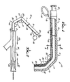
- FIG. 1 illustrates a guiding catheter 10 embodying features of the invention which generally comprises an elongated tubular member 11 with a proximal portion 12 and a distal portion 13.
- a first relatively large diameter longitudinally extending lumen 14 and a second relatively small diameter longitudinally extending lumen 15 are provided in tubular member 11.
- the diameter of lumen 14 is of relatively large diameter to facilitate the passage of guidewires, dilatation catheters and the like therethrough.
- Lumen 15 is of smaller diameter than lumen 14 and has disposed therein a control line 16 which is fixed to the distal tip 17 by adhesive 18.
- a Luer fitting 20 is provided at the proximal end of the tubular member 11 and is in communication with lumen 14 for connecting the catheter to an adapter (not shown).
- the distal portion 13 of the tubular member 11 has two articulated sections 21 and 22 which are relatively stiff and preformed into a desired shape with included angles A and B therebetween.
- the material at the junctions between sections 21 and 22 and section 21 and the main section 23 can be made more flexible to facilitate the bending of sections 21 and 22.
- the entire catheter can be formed from suitable plastic materials as a unitary structure with the junctions between the sections being irradiated or otherwise treated to make them more flexible when the distal sections are preformed into the desired shape.
- the main section 23 and the distal tip sections 21 and 22 and the joints therebetween can be formed separately and joined together by suitable means such as heat sealing or adhesive bonding. While the guiding catheter 10 is shown in the drawings in a classic Judkins left configuration, it should be apparent that other preformed configurations can be made with various numbers of articulated sections.
- a control line 16 extends through lumen 15. It is secured at the distal end thereof to the distal tip 17 by adhesive 18 and a ring 24 is connected to the proximal end of the control line 16 to facilitate applying tension thereto when deflecting the distal sections 21 and 22.
- the control line 16 may be fabricated of any suitable material such as a metal or plastic and may be in the form of a flexible wire or cable.
- the guiding catheter 10 can be fabricated of a variety of suitable materials, and it can be formed by any suitable process such as extrusion.
- the tubular member 11 comprises a tubular sheath 25 of generally circular cross section which is formed of braided or wound aramid fibers, such as DuPont's Kevlar fibers, impregnated with a plastic material, such as polyurethane or epoxy resin.
- the large lumen 14 is formed with a liner 26 of lubricious material such as polytetrafluoroethylene (Teflon) which is positioned eccentrically within the tubular sheath 25.
- Teflon polytetrafluoroethylene
- the smaller lumen 15 is formed by a polyimide tube 27 which is positioned in the crescent-shaped space 28 between Teflon liner 26 and sheath 25.
- a suitable polyimide tubing is the Micro-Bore TM tubing sold by Polymicro Technologies of Phoenix, Arizona.
- a polyethylene jacket 29 surrounds the tubular sheath 25.
- FIG. 4 An alternate embodiment is shown in FIG. 4 wherein the shaft 11 of catheter 10 has a tubular sheath 30 of wound or braided aramid fibers, such as Kevlar, impregnated with polyurethane or with epoxy resin.
- a layer or jacket 31 of polyethylene is provided on the outside and an inner layer 32 of Teflon is positioned concentrically within the sheath 30.
- a small diameter tube 33, preferably formed of polyimide, which defines small lumen 15 is disposed in space 34 between sheath 30 and Teflon lining 32.
- the space 34 can be filled with any suitable filler material.
- the tubular shafts 11 and 20 typically have outer diameters on the order of 0.118 inch (3 mm).
- the lumen 14 has a diameter on the order of .078 inch (2 mm) and lumen 15 has a diameter on the order of .010 inch (.25 mm).
- Sheaths 25 and 30 have wall thicknesses on the order of .006 inch (.15 mm).
- the Teflon layers 26 and 32 have a minimum thickness on the order of .003 inch (1.076 mm).
- Control line 16 has a diameter on the order of .004 inch (.1 mm) and polyimide tubes 27 and 32 have a wall thickness on the order of .001 inch (.025 mm).
- the deflection of the distal portions 21 and 22 of catheter 10 is best illustrated in FIG. 2.
- the catheter By pulling tension via a device on the proximal end of control line 16 at the proximal end of the catheter 10, the catheter flexes at location 35 between the main section 23 and distal section 21 and location 36 between distal sections 21 and 22 there by decreasing the included angles A and B.
- the deflection of the articulated sections 21 and 22 can be used to guide the distal tip 13 of the guiding catheter to its proper position within a coronary artery 37 and the stiffness imparted to the distal portion of the guiding catheter can be used to assist a dilatation catheter 38 to be advanced through the guiding catheter 10 and across a lesion 39.
- a force represented by the arrow 40 pulling on the proximal end of the control line 16 produces forces represented by arrows 41 and 42 at locations 35 and 36 which combine to produce a resultant force having an axial component represented by arrow 43.
- the added axial force 43 can be sufficient to advance the dilatation catheter 38 across the lesion 39.
- the guiding catheter 10 and dilatation catheter 38 are introduced together into the cardiovascular system of a patient with the distal end portion of the dilatation catheter 38 retracted from distal tip 17 of the guiding catheter 10.
- the configuration of the distal tip of catheter 10 can be changed by pulling proximally on control line 16 outside of the patient's body to change the angles A and B between the main section 23 and the distal sections 21 and 22 to guide the distal tip 17 to the desired location.
- control line can be pulled proximally to return the shape of the distal portion 13 to its preformed shape.
- FIG. 5 illustrates a presently preferred manipulator 50 which is adapted to move control wire 16 and thereby change the shape of the distal end of the guiding catheter (not shown) in accordance with the invention.
- the proximal end 51 of control wire 16 is secured to the interior of movable threaded member 52 which is slidably disposed within manipulator housing 53.
- a collar 54 is rotatably mounted about the proximal end of manipulator housing 53 and is provided with threads 55 on the interior thereof which are adapted to engage the exterior threaded section 56 on the movable member 52.
- the movable member 52 is provided with a plurality of extensions 57 adjacent the threaded section 56 thereof which are adapted to slidably engage ribs or guides 58 provided on the interior surface of the housing 53.
- Manual rotation of collar 54 causes relative movement between the movable member 52 and the housing 53.
- the outer surface 59 of collar 54 can be knurled as shown to facilitate the manual rotation thereof.
- the outer surface of the movable member 52 on the end thereof opposite the threaded section is provided with a ring to prevent loss of fluids.
- a stepping element 60 is provided in the distal end of the manipulator housing 53 to prevent further distal movement of the movable member 52. Extensions 57 stop the proximal movement thereof.
- the collar 54 is rotated clockwise to apply tension to control wire 16 and counterclockwise to release applied tension.
- the various components of manipulator 50 can be made of suitable plastic materials such as polyethylene.
Abstract
Description
- This invention generally relates to vascular catheters and particularly to guiding catheters for the placement of intracoronary devices within a patient's vascular system such as dilatation catheters in procedures such as percutaneous transluminal coronary angioplasty (PTCA).
- In the classic PTCA procedure, a guiding catheter having a preformed distal tip is percutaneously introduced into the cardiovascular system of a patient and advanced therein until the distal tip thereof is in the ostium of the desired artery. A guidewire and a dilatation catheter having a balloon on the distal end thereof are introduced through the guiding catheter with the guidewire slidably disposed within an inner lumen of the dilatation catheter. The guidewire is first advanced into the patient's coronary vasculature until the distal end of the guidewire crosses the lesion to be dilated, then the dilatation catheter is advanced over the previously introduced guidewire until the dilatation balloon is properly positioned across the lesion. Once in position across the lesion, the balloon is inflated to a predetermined size with radiopaque liquid at relatively high pressures (e.g., generally 4-12 atmospheres) to compress and split the atherosclerotic plaque of the lesion against the inside of the artery wall to thereby dilate the lumen of the diseased artery. The balloon is then deflated so that the dilatation catheter can be removed and blood flow resumed through the dilated artery.
- Further details of guiding catheters, dilatation catheters, guidewires, and the like for angioplasty procedures can be found in U. S. Patent 4,323,071 (Simpson-Robert); U. S. Patent 4,439,185 (Lundquist); U. S. Patent 4,468,224 (Enzmann et al.); U. S. Patent 4,516,972 (Samson), U. S. Patent 4,538,622 (Samson et al.); U. S. Patent 4,582,185 (Samson); U. S. Patent 4,616,652 (Simpson); and U. S. Patent 4,638,805 (Powell) which are hereby incorporated herein in their entirety by reference thereto.
- Frequently, sufficient force cannot be applied to the proximal end of a dilatation catheter to advance the balloon thereof across a lesion. Additional axial force can be supplied to the dilatation catheter by buttressing the guiding catheter against a wall of the aorta, by deep seating the guiding catheter tip well into the coronary ostium, by choosing a guiding catheter with a different distal configuration, or by increasing the stiffness of the guiding catheter. However, in practice, these methods are not always successful and no dilatation of a stenosis can occur unless the balloon crosses the lesion.
- Steerable dilatation catheters with built-in or fixed guidewires or guiding elements are used with greater frequency because their deflated profiles are generally smaller than conventional dilatation catheters with movable guidewires having the same inflated balloon size. Moreover, the fixed guiding elements in the steerable dilatation catheters provide greater pushability which allows them to cross much tighter lesions than dilatation catheters with movable guidewires. Further details of steerable dilatation catheters may be found in U. S. Patent 4,582,181 (Samson), U. S. Patent 4,619,263 (Frisbie et al.), U. S. Patent 4,641,654 (Samson et al.), and U. S. Patent 4,664,113 (Frisbie et al.) which are hereby incorporated in their entirety by reference thereto.
- While the tubular members forming the catheter body utilizing a movable guidewire could be made from stiffer material or thicker walled tubing to increase the pushability of the catheter, such added stiffness would reduce the flexibility of the distal end of the catheter which allows the catheter to pass through the tortuous passageways of a patient's vascular system.
- Other types of intracoronary catheters such as those used for mechanical and laser based atherectomy procedures and angioscopic catheters generally have much stiffer shafts than balloon dilatation catheters. As a result, the guiding catheter frequently is not sufficiently strong to maintain its preformed distal shape when these stiffer catheters are disposed within the guiding catheter and advanced into and through coronary stenoses. This makes the placement of such stiffer catheters much more difficult.
- In some situations, the preformed distal curvature of the guiding catheters may not be the exact curvature needed for the placement of the distal tip in the desired location within the patient's cardiovascular system.
- When many of the aforesaid problems occur, the only solution is to withdraw the guiding catheter from the patient's body and replace it with a guiding catheter having a different curvature or stiffness. This recatheterization not only increases the time required for the procedure but it also adds further arterial trauma. Withdrawal of a guiding catheter necessitates withdrawing the guidewire and balloon dilatation catheter out of the coronary stenosis, which increases the risk of acute coronary closure and myocardial infarction if the coronary stenosis has not yet been properly dilated.
- What has been needed and heretofore unavailable is a guiding catheter which has a distal portion or segment, the shape and stiffness of which can be changed from the proximal end after it has been inserted into the patient and which can aid in providing support to a dilatation catheter when the balloon thereof is being advanced across a tight lesion. The present invention satisfies this need.
- The present invention is directed to an improved guiding catheter with a deflectable distal segment which is operable from the proximal end thereof and which has sufficient stiffness or strength to support dilatation catheters and other type catheters for their proper placement within a patient's coronary vasculature.
- The guiding catheter in accordance with the invention generally comprises a tubular member having a proximal portion, a main portion, and a distal portion, the distal portion having at least one section which is preformed at an angle with respect to the main portion; a first lumen of relatively large diameter disposed within the tubular member which extends along the length thereof and which is adapted to receive catheters or guidewires therethrough; a second lumen of relatively small diameter disposed within the tubular member, extending along the length thereof; a control line which is disposed within the second lumen and which is secured at the distal tip thereof to the distal tip of the tubular member; and means at the proximal end of the control line to axially move the control line within the second lumen to thereby change the shape of the distal portion of the catheter from its preformed shape.
- The articulated, relatively stiff distal sections allow the shape of the distal portion of the guiding catheter to be changed from the proximal end to a more desirable configuration or to be returned to the preformed shape should the tip be deformed once the catheter is disposed within a patient. Moreover, this deflectability, which strengthens and stiffens the guiding catheter, can also be used to add an axial force to a dilatation catheter disposed therein when pushing the dilatation catheter across a tight lesion.
- These and other advantages of the invention will become more apparent from the following detailed description of the invention including the accompanying exemplary drawings.
-
- FIG. 1 is a centerline sectional view of an articulated guiding catheter embodying features of the invention;
- FIG. 2 is a schematic operational view, illustrating the operation of the articulated guiding catheter of FIG. 1;
- FIG. 3 is a cross-sectional view taken along line 3-3 in FIG. 1;
- FIG. 4 is a cross-sectional view similar to that shown in FIG. 3 of an alternative construction; and
- FIG. 5 is a cross-sectional view of a manipulator for applying tension to the control line in the guiding catheter.
- FIG. 1 illustrates a guiding
catheter 10 embodying features of the invention which generally comprises an elongated tubular member 11 with aproximal portion 12 and adistal portion 13. A first relatively large diameter longitudinally extendinglumen 14 and a second relatively small diameter longitudinally extendinglumen 15 are provided in tubular member 11. The diameter oflumen 14 is of relatively large diameter to facilitate the passage of guidewires, dilatation catheters and the like therethrough.Lumen 15 is of smaller diameter thanlumen 14 and has disposed therein acontrol line 16 which is fixed to the distal tip 17 by adhesive 18. ALuer fitting 20 is provided at the proximal end of the tubular member 11 and is in communication withlumen 14 for connecting the catheter to an adapter (not shown). - The
distal portion 13 of the tubular member 11 has two articulatedsections sections section 21 and themain section 23 can be made more flexible to facilitate the bending ofsections main section 23 and thedistal tip sections catheter 10 is shown in the drawings in a classic Judkins left configuration, it should be apparent that other preformed configurations can be made with various numbers of articulated sections. - A
control line 16 extends throughlumen 15. It is secured at the distal end thereof to the distal tip 17 by adhesive 18 and aring 24 is connected to the proximal end of thecontrol line 16 to facilitate applying tension thereto when deflecting thedistal sections control line 16 may be fabricated of any suitable material such as a metal or plastic and may be in the form of a flexible wire or cable. - The guiding
catheter 10 can be fabricated of a variety of suitable materials, and it can be formed by any suitable process such as extrusion. In the embodiment shown in FIG. 3, the tubular member 11 comprises atubular sheath 25 of generally circular cross section which is formed of braided or wound aramid fibers, such as DuPont's Kevlar fibers, impregnated with a plastic material, such as polyurethane or epoxy resin. Thelarge lumen 14 is formed with aliner 26 of lubricious material such as polytetrafluoroethylene (Teflon) which is positioned eccentrically within thetubular sheath 25. Thesmaller lumen 15 is formed by apolyimide tube 27 which is positioned in the crescent-shaped space 28 between Teflonliner 26 andsheath 25. A suitable polyimide tubing is the Micro-BoreTM tubing sold by Polymicro Technologies of Phoenix, Arizona. Apolyethylene jacket 29 surrounds thetubular sheath 25. - An alternate embodiment is shown in FIG. 4 wherein the shaft 11 of
catheter 10 has atubular sheath 30 of wound or braided aramid fibers, such as Kevlar, impregnated with polyurethane or with epoxy resin. A layer orjacket 31 of polyethylene is provided on the outside and aninner layer 32 of Teflon is positioned concentrically within thesheath 30. Asmall diameter tube 33, preferably formed of polyimide, which definessmall lumen 15 is disposed inspace 34 betweensheath 30 and Teflonlining 32. Thespace 34 can be filled with any suitable filler material. - In the embodiments shown in FIGS. 3 and 4, the
tubular shafts 11 and 20 typically have outer diameters on the order of 0.118 inch (3 mm). Thelumen 14 has a diameter on the order of .078 inch (2 mm) andlumen 15 has a diameter on the order of .010 inch (.25 mm).Sheaths layers Control line 16 has a diameter on the order of .004 inch (.1 mm) andpolyimide tubes - The deflection of the
distal portions catheter 10 is best illustrated in FIG. 2. By pulling tension via a device on the proximal end ofcontrol line 16 at the proximal end of thecatheter 10, the catheter flexes atlocation 35 between themain section 23 anddistal section 21 andlocation 36 betweendistal sections - The deflection of the articulated
sections distal tip 13 of the guiding catheter to its proper position within acoronary artery 37 and the stiffness imparted to the distal portion of the guiding catheter can be used to assist adilatation catheter 38 to be advanced through the guidingcatheter 10 and across a lesion 39. In this latter instance, when further movement ofdilatation catheter 38 is resisted by a force represented by thearrow 40, pulling on the proximal end of thecontrol line 16 produces forces represented byarrows 41 and 42 atlocations dilatation catheter 38 across the lesion 39. - Usually, the guiding
catheter 10 anddilatation catheter 38 are introduced together into the cardiovascular system of a patient with the distal end portion of thedilatation catheter 38 retracted from distal tip 17 of the guidingcatheter 10. As the catheters are percutaneously introduced into the patient, the configuration of the distal tip ofcatheter 10 can be changed by pulling proximally oncontrol line 16 outside of the patient's body to change the angles A and B between themain section 23 and thedistal sections - When a stiff catheter or other intracoronary device deforms the preformed
distal portion 13 with its passage, the control line can be pulled proximally to return the shape of thedistal portion 13 to its preformed shape. - FIG. 5 illustrates a presently preferred
manipulator 50 which is adapted to movecontrol wire 16 and thereby change the shape of the distal end of the guiding catheter (not shown) in accordance with the invention. The proximal end 51 ofcontrol wire 16 is secured to the interior of movable threadedmember 52 which is slidably disposed within manipulator housing 53. Acollar 54 is rotatably mounted about the proximal end of manipulator housing 53 and is provided withthreads 55 on the interior thereof which are adapted to engage the exterior threadedsection 56 on themovable member 52. Themovable member 52 is provided with a plurality of extensions 57 adjacent the threadedsection 56 thereof which are adapted to slidably engage ribs or guides 58 provided on the interior surface of the housing 53. - Manual rotation of
collar 54 causes relative movement between themovable member 52 and the housing 53. Theouter surface 59 ofcollar 54 can be knurled as shown to facilitate the manual rotation thereof. The outer surface of themovable member 52 on the end thereof opposite the threaded section is provided with a ring to prevent loss of fluids. A stepping element 60 is provided in the distal end of the manipulator housing 53 to prevent further distal movement of themovable member 52. Extensions 57 stop the proximal movement thereof. To operate themanipulator 50, thecollar 54 is rotated clockwise to apply tension to controlwire 16 and counterclockwise to release applied tension. The various components ofmanipulator 50 can be made of suitable plastic materials such as polyethylene. - It is apparent from the foregoing that a new and improved guiding catheter and method of using the same have been provided. While only certain presently preferred embodiments have been described in detail, as will be apparent to those familiar with the art, certain changes and modifications can be made without departing from the scope of the invention as defined by the following claims.
Claims (14)
Applications Claiming Priority (2)
| Application Number | Priority Date | Filing Date | Title |
|---|---|---|---|
| US250709 | 1988-09-28 | ||
| US07/250,709 US4898577A (en) | 1988-09-28 | 1988-09-28 | Guiding cathether with controllable distal tip |
Publications (3)
| Publication Number | Publication Date |
|---|---|
| EP0361314A2 true EP0361314A2 (en) | 1990-04-04 |
| EP0361314A3 EP0361314A3 (en) | 1990-09-12 |
| EP0361314B1 EP0361314B1 (en) | 1996-06-05 |
Family
ID=22948838
Family Applications (1)
| Application Number | Title | Priority Date | Filing Date |
|---|---|---|---|
| EP89117474A Expired - Lifetime EP0361314B1 (en) | 1988-09-28 | 1989-09-21 | Guiding catheter with controllable distal tip |
Country Status (5)
| Country | Link |
|---|---|
| US (1) | US4898577A (en) |
| EP (1) | EP0361314B1 (en) |
| JP (1) | JPH02193681A (en) |
| CA (1) | CA1309633C (en) |
| DE (1) | DE68926599T2 (en) |
Cited By (15)
| Publication number | Priority date | Publication date | Assignee | Title |
|---|---|---|---|---|
| FR2662778A1 (en) * | 1990-05-31 | 1991-12-06 | Chevallier Rene | Rod for operating an intervention device, controlled in terms of flexion |
| WO1993023107A1 (en) * | 1992-05-11 | 1993-11-25 | Advanced Cardiovascular Systems, Inc. | Intraluminal catheter with a composite shaft |
| EP0628323A1 (en) * | 1993-06-11 | 1994-12-14 | Cordis Europa N.V. | Controllably bendable catheter |
| FR2713492A1 (en) * | 1993-12-09 | 1995-06-16 | Microfil Ind Sa | Flexible tubular guide |
| EP0737486A2 (en) * | 1995-04-14 | 1996-10-16 | Daig Corporation | Guiding introducer used for medical procedures within the right ventricle associated with the right ventricular outflow track |
| EP0738518A2 (en) * | 1995-04-17 | 1996-10-23 | Daig Corporation | Guiding introducers used for medical procedures within the right ventricle associated with the tricuspid valve |
| US5814027A (en) * | 1993-11-03 | 1998-09-29 | Daig Corporation | Guiding introducer used for medical procedures within the right ventricle associated with the right ventricular outflow track |
| EP0868923A2 (en) * | 1997-04-04 | 1998-10-07 | Eclipse Surgical Technologies, Inc. | Steerable catheter |
| WO1999004728A1 (en) * | 1997-07-24 | 1999-02-04 | Medtronic, Inc. | Disposable delivery device for endoluminal prostheses |
| EP0950424A3 (en) * | 1998-04-17 | 1999-11-10 | REHAU AG + Co | Method of manufacture for reinforced medical tubings |
| EP0904797A3 (en) * | 1997-09-24 | 2000-08-09 | ECLIPSE SURGICAL TECHNOLOGIES, Inc. | Steerable catheter with tip alignment and surface contact detector |
| EP0908194A3 (en) * | 1997-09-24 | 2000-08-09 | ECLIPSE SURGICAL TECHNOLOGIES, Inc. | Drug delivery catheter with tip alignment |
| US7824377B2 (en) | 2007-12-21 | 2010-11-02 | St. Jude Medical, Atrial Fibrillation Division, Inc. | Tissue anchoring catheter systems and methods |
| US10258802B2 (en) | 2015-11-20 | 2019-04-16 | Cardiac Pacemakers, Inc. | Delivery devices and methods for leadless cardiac devices |
| US10500395B2 (en) | 2015-11-20 | 2019-12-10 | Cardiac Pacemakers, Inc. | Delivery devices and methods for leadless cardiac devices |
Families Citing this family (276)
| Publication number | Priority date | Publication date | Assignee | Title |
|---|---|---|---|---|
| US5435805A (en) * | 1992-08-12 | 1995-07-25 | Vidamed, Inc. | Medical probe device with optical viewing capability |
| US5421819A (en) * | 1992-08-12 | 1995-06-06 | Vidamed, Inc. | Medical probe device |
| US5370675A (en) * | 1992-08-12 | 1994-12-06 | Vidamed, Inc. | Medical probe device and method |
| US5542915A (en) * | 1992-08-12 | 1996-08-06 | Vidamed, Inc. | Thermal mapping catheter with ultrasound probe |
| US5308324A (en) * | 1989-01-09 | 1994-05-03 | Pilot Cardiovascular Systems, Inc. | Steerable medical device |
| US5480382A (en) * | 1989-01-09 | 1996-01-02 | Pilot Cardiovascular Systems, Inc. | Steerable medical device |
| US5372587A (en) * | 1989-01-09 | 1994-12-13 | Pilot Cariovascular Systems, Inc. | Steerable medical device |
| US5484409A (en) * | 1989-08-25 | 1996-01-16 | Scimed Life Systems, Inc. | Intravascular catheter and method for use thereof |
| US5114403A (en) * | 1989-09-15 | 1992-05-19 | Eclipse Surgical Technologies, Inc. | Catheter torque mechanism |
| US5078725A (en) * | 1989-11-09 | 1992-01-07 | C. R. Bard, Inc. | Balloon catheter and techniques for dilating obstructed lumens and other luminal procedures |
| US5041085A (en) * | 1990-02-26 | 1991-08-20 | Cook Incorporated | Percutaneous lockable sleeve catheter |
| US5342394A (en) * | 1990-05-16 | 1994-08-30 | Olympus Optical Co., Ltd. | Apparatus for blocking a vein branch and method of blocking a vein branch |
| US5190528A (en) * | 1990-10-19 | 1993-03-02 | Boston University | Percutaneous transseptal left atrial cannulation system |
| US5445625A (en) | 1991-01-23 | 1995-08-29 | Voda; Jan | Angioplasty guide catheter |
| DE568624T1 (en) * | 1991-01-23 | 1994-09-22 | Jan Voda | CONSTRUCTION OF A GUIDE CATHETER. |
| US5409453A (en) * | 1992-08-12 | 1995-04-25 | Vidamed, Inc. | Steerable medical probe with stylets |
| US6821287B1 (en) | 1991-05-24 | 2004-11-23 | Advanced Cardiovascular Systems, Inc. | Multi-mode vascular catheter system |
| US5185004A (en) * | 1991-06-03 | 1993-02-09 | Danforth Biomedical, Inc. | Turn-limiting proximal adaptor for steerable catheter systems |
| US5135535A (en) | 1991-06-11 | 1992-08-04 | Advanced Cardiovascular Systems, Inc. | Catheter system with catheter and guidewire exchange |
| US7074231B2 (en) * | 1991-06-13 | 2006-07-11 | Advanced Cardiovascular Systems, Inc. | Convertible mode vascular catheter system |
| US5976107A (en) * | 1991-07-05 | 1999-11-02 | Scimed Life Systems. Inc. | Catheter having extendable guide wire lumen |
| US5490837A (en) * | 1991-07-05 | 1996-02-13 | Scimed Life Systems, Inc. | Single operator exchange catheter having a distal catheter shaft section |
| US5281203A (en) * | 1991-07-05 | 1994-01-25 | Scimed Life Systems, Inc. | Guide wire and sheath for single operator exchange |
| US5290229A (en) * | 1991-07-15 | 1994-03-01 | Paskar Larry D | Transformable catheter and method |
| US5304131A (en) * | 1991-07-15 | 1994-04-19 | Paskar Larry D | Catheter |
| US6866650B2 (en) | 1991-07-16 | 2005-03-15 | Heartport, Inc. | System for cardiac procedures |
| US5168864A (en) * | 1991-09-26 | 1992-12-08 | Clarus Medical Systems, Inc. | Deflectable endoscope |
| US5275151A (en) * | 1991-12-11 | 1994-01-04 | Clarus Medical Systems, Inc. | Handle for deflectable catheter |
| JPH06511181A (en) * | 1992-03-18 | 1994-12-15 | ザ・スペクトラネティックス・コーポレーション | Fiber optic catheter with flexible tip |
| US5352197A (en) * | 1992-03-18 | 1994-10-04 | The Spectranetics Corporation | Turn limiter for a catheter with twistable tip |
| US5259377A (en) * | 1992-03-30 | 1993-11-09 | Stephen M. Daugherty | Endotracheal tube stylet |
| US5306263A (en) | 1992-05-01 | 1994-04-26 | Jan Voda | Catheter |
| NL9201132A (en) * | 1992-06-25 | 1994-01-17 | Hooft Eric T | GUIDE SLEEVE WITH AT LEAST ONE CHANNEL FOR LEADING A CABLE. |
| US5720719A (en) * | 1992-08-12 | 1998-02-24 | Vidamed, Inc. | Ablative catheter with conformable body |
| US5720718A (en) * | 1992-08-12 | 1998-02-24 | Vidamed, Inc. | Medical probe apparatus with enhanced RF, resistance heating, and microwave ablation capabilities |
| US5514131A (en) | 1992-08-12 | 1996-05-07 | Stuart D. Edwards | Method for the ablation treatment of the uvula |
| US5630794A (en) * | 1992-08-12 | 1997-05-20 | Vidamed, Inc. | Catheter tip and method of manufacturing |
| US5672153A (en) * | 1992-08-12 | 1997-09-30 | Vidamed, Inc. | Medical probe device and method |
| US5470308A (en) * | 1992-08-12 | 1995-11-28 | Vidamed, Inc. | Medical probe with biopsy stylet |
| US5456662A (en) * | 1993-02-02 | 1995-10-10 | Edwards; Stuart D. | Method for reducing snoring by RF ablation of the uvula |
| US5556377A (en) * | 1992-08-12 | 1996-09-17 | Vidamed, Inc. | Medical probe apparatus with laser and/or microwave monolithic integrated circuit probe |
| US5318526A (en) * | 1992-09-29 | 1994-06-07 | Neuro Navigational Corporation | Flexible endoscope with hypotube activating wire support |
| US5203776A (en) * | 1992-10-09 | 1993-04-20 | Durfee Paul J | Catheter |
| CA2109980A1 (en) * | 1992-12-01 | 1994-06-02 | Mir A. Imran | Steerable catheter with adjustable bend location and/or radius and method |
| US5368564A (en) * | 1992-12-23 | 1994-11-29 | Angeion Corporation | Steerable catheter |
| US5306245A (en) * | 1993-02-23 | 1994-04-26 | Advanced Surgical Inc. | Articulating device |
| US5364352A (en) * | 1993-03-12 | 1994-11-15 | Heart Rhythm Technologies, Inc. | Catheter for electrophysiological procedures |
| US5378234A (en) * | 1993-03-15 | 1995-01-03 | Pilot Cardiovascular Systems, Inc. | Coil polymer composite |
| US5391146A (en) * | 1993-06-24 | 1995-02-21 | Conceptus, Inc. | Mechanism for manipulating the distal end of a biomedical device |
| AU7404994A (en) * | 1993-07-30 | 1995-02-28 | Regents Of The University Of California, The | Endocardial infusion catheter |
| US6001085A (en) * | 1993-08-13 | 1999-12-14 | Daig Corporation | Coronary sinus catheter |
| US5984909A (en) * | 1993-08-13 | 1999-11-16 | Daig Corporation | Coronary sinus catheter |
| US5456680A (en) * | 1993-09-14 | 1995-10-10 | Spectranetics Corp | Fiber optic catheter with shortened guide wire lumen |
| DE29522101U1 (en) | 1994-06-08 | 1999-12-09 | Cardiovascular Concepts Inc | Endoluminal prosthesis |
| NL9401107A (en) * | 1994-07-01 | 1996-02-01 | Cordis Europ | Controlled bendable catheter. |
| US5857997A (en) * | 1994-11-14 | 1999-01-12 | Heart Rhythm Technologies, Inc. | Catheter for electrophysiological procedures |
| US5666970A (en) * | 1995-05-02 | 1997-09-16 | Heart Rhythm Technologies, Inc. | Locking mechanism for catheters |
| US5681280A (en) * | 1995-05-02 | 1997-10-28 | Heart Rhythm Technologies, Inc. | Catheter control system |
| USD381076S (en) * | 1995-05-02 | 1997-07-15 | Heart Rhythm Technologies, Inc. | Manipulation handle |
| US5741320A (en) * | 1995-05-02 | 1998-04-21 | Heart Rhythm Technologies, Inc. | Catheter control system having a pulley |
| US6251104B1 (en) * | 1995-05-10 | 2001-06-26 | Eclipse Surgical Technologies, Inc. | Guiding catheter system for ablating heart tissue |
| US5591141A (en) * | 1995-09-15 | 1997-01-07 | Megadyne Medical Products, Inc. | Suction coagulator bending tool |
| US5632734A (en) * | 1995-10-10 | 1997-05-27 | Guided Medical Systems, Inc. | Catheter shape control by collapsible inner tubular member |
| DE898480T1 (en) * | 1996-01-19 | 1999-10-07 | Scimed Life Systems Inc | CATHETER WITH A CURVE WITH INCREASING RADIUS |
| AUPN775296A0 (en) † | 1996-01-25 | 1996-02-22 | Endogad Research Pty Limited | Directional catheter |
| US5882346A (en) * | 1996-07-15 | 1999-03-16 | Cardiac Pathways Corporation | Shapable catheter using exchangeable core and method of use |
| US5820592A (en) * | 1996-07-16 | 1998-10-13 | Hammerslag; Gary R. | Angiographic and/or guide catheter |
| US6083232A (en) * | 1996-09-27 | 2000-07-04 | Advanced Cardivascular Systems, Inc. | Vibrating stent for opening calcified lesions |
| US5851179A (en) * | 1996-10-10 | 1998-12-22 | Nellcor Puritan Bennett Incorporated | Pulse oximeter sensor with articulating head |
| US6051008A (en) | 1996-12-02 | 2000-04-18 | Angiotrax, Inc. | Apparatus having stabilization members for percutaneously performing surgery and methods of use |
| US6120520A (en) | 1997-05-27 | 2000-09-19 | Angiotrax, Inc. | Apparatus and methods for stimulating revascularization and/or tissue growth |
| US6102926A (en) | 1996-12-02 | 2000-08-15 | Angiotrax, Inc. | Apparatus for percutaneously performing myocardial revascularization having means for sensing tissue parameters and methods of use |
| US6210312B1 (en) | 1997-05-20 | 2001-04-03 | Advanced Cardiovascular Systems, Inc. | Catheter and guide wire assembly for delivery of a radiation source |
| US6159177A (en) * | 1997-09-30 | 2000-12-12 | Scimed Life Systems | Drainage catheter anchor locking mechanisms |
| US5935141A (en) * | 1997-10-30 | 1999-08-10 | Partisan Management Group | Interventional cardiology instrument controlled from an intracoronary reference |
| US6251092B1 (en) | 1997-12-30 | 2001-06-26 | Medtronic, Inc. | Deflectable guiding catheter |
| US5984946A (en) * | 1998-02-27 | 1999-11-16 | Gupta; Mukesh | Diagnostic and guiding catheter |
| US8075570B2 (en) * | 2001-11-28 | 2011-12-13 | Aptus Endosystems, Inc. | Intraluminal prosthesis attachment systems and methods |
| US7491232B2 (en) * | 1998-09-18 | 2009-02-17 | Aptus Endosystems, Inc. | Catheter-based fastener implantation apparatus and methods with implantation force resolution |
| US7591842B2 (en) * | 1998-03-13 | 2009-09-22 | Aptus Endosystems, Inc. | Endovascular prosthesis with suture holder |
| US5947927A (en) * | 1998-03-23 | 1999-09-07 | Scimed Life Systems, Inc. | Convertible catheter having a single proximal lumen |
| US6059739A (en) * | 1998-05-29 | 2000-05-09 | Medtronic, Inc. | Method and apparatus for deflecting a catheter or lead |
| JP2002526193A (en) * | 1998-09-18 | 2002-08-20 | ユナイテッド ステイツ サージカル コーポレーション | Intravascular fastener applicator |
| US7972323B1 (en) * | 1998-10-02 | 2011-07-05 | Boston Scientific Scimed, Inc. | Steerable device for introducing diagnostic and therapeutic apparatus into the body |
| US6544215B1 (en) | 1998-10-02 | 2003-04-08 | Scimed Life Systems, Inc. | Steerable device for introducing diagnostic and therapeutic apparatus into the body |
| US6045530A (en) * | 1998-10-14 | 2000-04-04 | Heyer-Schulte Neurocare Inc. | Adjustable angle catheter |
| US6068621A (en) * | 1998-11-20 | 2000-05-30 | Embol X, Inc. | Articulating cannula |
| US6171295B1 (en) * | 1999-01-20 | 2001-01-09 | Scimed Life Systems, Inc. | Intravascular catheter with composite reinforcement |
| US6445958B1 (en) | 1999-04-15 | 2002-09-03 | Intermedics, Inc. | Steerable coronary sinus defibrillation lead |
| AU5629300A (en) * | 1999-07-29 | 2001-02-19 | Scope Medical, Inc. | Steerable medical device |
| US6423059B1 (en) * | 1999-11-16 | 2002-07-23 | Sulzer Medica Usa Inc. | Radio frequency ablation apparatus with remotely articulating and self-locking electrode wand |
| US7497844B2 (en) * | 2000-03-31 | 2009-03-03 | Medtronic, Inc. | System and method for positioning implantable medical devices within coronary veins |
| KR20000054094A (en) * | 2000-05-22 | 2000-09-05 | 박헌규 | flexible tip Cardiac Catheter |
| AU2001273421A1 (en) * | 2000-07-13 | 2002-01-30 | Bioheart, Inc. | Deployment system for myocardial cellular material |
| US6726700B1 (en) | 2000-08-21 | 2004-04-27 | Counter Clockwise, Inc. | Manipulatable delivery catheter for occlusive devices |
| US6482221B1 (en) * | 2000-08-21 | 2002-11-19 | Counter Clockwise, Inc. | Manipulatable delivery catheter for occlusive devices (II) |
| US6595983B2 (en) | 2000-12-07 | 2003-07-22 | Jan K. Voda | Guide or diagnostic catheter for right coronary artery |
| US20040138621A1 (en) * | 2003-01-14 | 2004-07-15 | Jahns Scott E. | Devices and methods for interstitial injection of biologic agents into tissue |
| US6837848B2 (en) * | 2003-01-15 | 2005-01-04 | Medtronic, Inc. | Methods and apparatus for accessing and stabilizing an area of the heart |
| US7628780B2 (en) * | 2001-01-13 | 2009-12-08 | Medtronic, Inc. | Devices and methods for interstitial injection of biologic agents into tissue |
| US7740623B2 (en) * | 2001-01-13 | 2010-06-22 | Medtronic, Inc. | Devices and methods for interstitial injection of biologic agents into tissue |
| DE10105592A1 (en) * | 2001-02-06 | 2002-08-08 | Achim Goepferich | Placeholder for drug release in the frontal sinus |
| US6716207B2 (en) | 2001-05-22 | 2004-04-06 | Scimed Life Systems, Inc. | Torqueable and deflectable medical device shaft |
| US7674245B2 (en) | 2001-06-07 | 2010-03-09 | Cardiac Pacemakers, Inc. | Method and apparatus for an adjustable shape guide catheter |
| US20030114832A1 (en) * | 2001-12-14 | 2003-06-19 | Kohler Robert Edward | Interventional catheter with three dimensional articulation |
| US6823217B2 (en) | 2001-08-21 | 2004-11-23 | Medtronic, Inc. | Method and apparatus for imparting curves in elongated implantable medical instruments |
| US20090099650A1 (en) * | 2001-11-28 | 2009-04-16 | Lee Bolduc | Devices, systems, and methods for endovascular staple and/or prosthesis delivery and implantation |
| US8231639B2 (en) | 2001-11-28 | 2012-07-31 | Aptus Endosystems, Inc. | Systems and methods for attaching a prosthesis within a body lumen or hollow organ |
| US9320503B2 (en) * | 2001-11-28 | 2016-04-26 | Medtronic Vascular, Inc. | Devices, system, and methods for guiding an operative tool into an interior body region |
| US7823267B2 (en) * | 2001-11-28 | 2010-11-02 | Aptus Endosystems, Inc. | Devices, systems, and methods for prosthesis delivery and implantation, including the use of a fastener tool |
| US20070073389A1 (en) * | 2001-11-28 | 2007-03-29 | Aptus Endosystems, Inc. | Endovascular aneurysm devices, systems, and methods |
| US20050070992A1 (en) * | 2001-11-28 | 2005-03-31 | Aptus Endosystems, Inc. | Prosthesis systems and methods sized and configured for the receipt and retention of fasteners |
| US20050177180A1 (en) | 2001-11-28 | 2005-08-11 | Aptus Endosystems, Inc. | Devices, systems, and methods for supporting tissue and/or structures within a hollow body organ |
| CA2464048C (en) * | 2001-11-28 | 2010-06-15 | Lee Bolduc | Endovascular aneurysm repair system |
| US7147657B2 (en) * | 2003-10-23 | 2006-12-12 | Aptus Endosystems, Inc. | Prosthesis delivery systems and methods |
| US6755812B2 (en) * | 2001-12-11 | 2004-06-29 | Cardiac Pacemakers, Inc. | Deflectable telescoping guide catheter |
| US6907298B2 (en) * | 2002-01-09 | 2005-06-14 | Medtronic, Inc. | Method and apparatus for imparting curves in implantable elongated medical instruments |
| US7717899B2 (en) | 2002-01-28 | 2010-05-18 | Cardiac Pacemakers, Inc. | Inner and outer telescoping catheter delivery system |
| US20030145122A1 (en) * | 2002-01-30 | 2003-07-31 | International Business Machines Corporation | Apparatus and method of allowing multiple partitions of a partitioned computer system to use a single network adapter |
| WO2003092765A2 (en) * | 2002-05-02 | 2003-11-13 | Dubrul William R | Upper airway device and method |
| US7033345B2 (en) * | 2002-05-21 | 2006-04-25 | Advanced Cardiovascular Systems, Inc. | Deflectable microimplant delivery system |
| US8956280B2 (en) | 2002-05-30 | 2015-02-17 | Intuitive Surgical Operations, Inc. | Apparatus and methods for placing leads using direct visualization |
| EP1513440A2 (en) * | 2002-05-30 | 2005-03-16 | The Board of Trustees of The Leland Stanford Junior University | Apparatus and method for coronary sinus access |
| US20030236493A1 (en) * | 2002-06-25 | 2003-12-25 | Medamicus, Inc. | Articulating handle for a deflectable catheter and method therefor |
| US7029468B2 (en) * | 2002-06-25 | 2006-04-18 | Enpath Medical, Inc. | Catheter assembly with side wall exit lumen and method therefor |
| US7115134B2 (en) * | 2002-07-22 | 2006-10-03 | Chambers Technology, Llc. | Catheter with flexible tip and shape retention |
| US20040039371A1 (en) * | 2002-08-23 | 2004-02-26 | Bruce Tockman | Coronary vein navigator |
| US8317816B2 (en) | 2002-09-30 | 2012-11-27 | Acclarent, Inc. | Balloon catheters and methods for treating paranasal sinuses |
| US20050256452A1 (en) * | 2002-11-15 | 2005-11-17 | Demarchi Thomas | Steerable vascular sheath |
| US20040102719A1 (en) * | 2002-11-22 | 2004-05-27 | Velocimed, L.L.C. | Guide wire control catheters for crossing occlusions and related methods of use |
| US7101361B2 (en) * | 2002-12-16 | 2006-09-05 | Medtronics, Inc. | Steerable medical device having means for imparting curves in the device and in elongated implantable medical instruments |
| WO2004068947A2 (en) * | 2003-02-03 | 2004-08-19 | Johns Hopkins University | Active mri intramyocardial injection catheter with deflectable distal section |
| AU2004212942A1 (en) | 2003-02-14 | 2004-09-02 | Depuy Spine, Inc. | In-situ formed intervertebral fusion device |
| US8308708B2 (en) * | 2003-07-15 | 2012-11-13 | Abbott Cardiovascular Systems Inc. | Deployment system for myocardial cellular material |
| US7763012B2 (en) * | 2003-09-02 | 2010-07-27 | St. Jude Medical, Cardiology Division, Inc. | Devices and methods for crossing a chronic total occlusion |
| US7588555B2 (en) | 2003-09-24 | 2009-09-15 | Enpath Medical, Inc. | Bi-directional catheter assembly and method therefor |
| US7481793B2 (en) * | 2003-12-10 | 2009-01-27 | Boston Scientic Scimed, Inc. | Modular steerable sheath catheters |
| US20050228452A1 (en) * | 2004-02-11 | 2005-10-13 | Mourlas Nicholas J | Steerable catheters and methods for using them |
| US20050197623A1 (en) * | 2004-02-17 | 2005-09-08 | Leeflang Stephen A. | Variable steerable catheters and methods for using them |
| US7867218B1 (en) | 2004-02-24 | 2011-01-11 | Voda Heart Technology, Llc | Steerable catheter for right coronary artery |
| US20070167682A1 (en) | 2004-04-21 | 2007-07-19 | Acclarent, Inc. | Endoscopic methods and devices for transnasal procedures |
| US9101384B2 (en) * | 2004-04-21 | 2015-08-11 | Acclarent, Inc. | Devices, systems and methods for diagnosing and treating sinusitis and other disorders of the ears, Nose and/or throat |
| US7803150B2 (en) | 2004-04-21 | 2010-09-28 | Acclarent, Inc. | Devices, systems and methods useable for treating sinusitis |
| US8702626B1 (en) | 2004-04-21 | 2014-04-22 | Acclarent, Inc. | Guidewires for performing image guided procedures |
| US7654997B2 (en) | 2004-04-21 | 2010-02-02 | Acclarent, Inc. | Devices, systems and methods for diagnosing and treating sinusitus and other disorders of the ears, nose and/or throat |
| US20060063973A1 (en) | 2004-04-21 | 2006-03-23 | Acclarent, Inc. | Methods and apparatus for treating disorders of the ear, nose and throat |
| US7361168B2 (en) | 2004-04-21 | 2008-04-22 | Acclarent, Inc. | Implantable device and methods for delivering drugs and other substances to treat sinusitis and other disorders |
| US8894614B2 (en) | 2004-04-21 | 2014-11-25 | Acclarent, Inc. | Devices, systems and methods useable for treating frontal sinusitis |
| US8932276B1 (en) | 2004-04-21 | 2015-01-13 | Acclarent, Inc. | Shapeable guide catheters and related methods |
| US8747389B2 (en) * | 2004-04-21 | 2014-06-10 | Acclarent, Inc. | Systems for treating disorders of the ear, nose and throat |
| US8864787B2 (en) | 2004-04-21 | 2014-10-21 | Acclarent, Inc. | Ethmoidotomy system and implantable spacer devices having therapeutic substance delivery capability for treatment of paranasal sinusitis |
| US7419497B2 (en) | 2004-04-21 | 2008-09-02 | Acclarent, Inc. | Methods for treating ethmoid disease |
| US20110004057A1 (en) * | 2004-04-21 | 2011-01-06 | Acclarent, Inc. | Systems and methods for transnasal dilation of passageways in the ear, nose or throat |
| US9351750B2 (en) | 2004-04-21 | 2016-05-31 | Acclarent, Inc. | Devices and methods for treating maxillary sinus disease |
| US10188413B1 (en) | 2004-04-21 | 2019-01-29 | Acclarent, Inc. | Deflectable guide catheters and related methods |
| US9554691B2 (en) * | 2004-04-21 | 2017-01-31 | Acclarent, Inc. | Endoscopic methods and devices for transnasal procedures |
| US8146400B2 (en) | 2004-04-21 | 2012-04-03 | Acclarent, Inc. | Endoscopic methods and devices for transnasal procedures |
| US9089258B2 (en) * | 2004-04-21 | 2015-07-28 | Acclarent, Inc. | Endoscopic methods and devices for transnasal procedures |
| US7462175B2 (en) | 2004-04-21 | 2008-12-09 | Acclarent, Inc. | Devices, systems and methods for treating disorders of the ear, nose and throat |
| US7410480B2 (en) * | 2004-04-21 | 2008-08-12 | Acclarent, Inc. | Devices and methods for delivering therapeutic substances for the treatment of sinusitis and other disorders |
| US20070208252A1 (en) | 2004-04-21 | 2007-09-06 | Acclarent, Inc. | Systems and methods for performing image guided procedures within the ear, nose, throat and paranasal sinuses |
| US7720521B2 (en) | 2004-04-21 | 2010-05-18 | Acclarent, Inc. | Methods and devices for performing procedures within the ear, nose, throat and paranasal sinuses |
| US20190314620A1 (en) | 2004-04-21 | 2019-10-17 | Acclarent, Inc. | Apparatus and methods for dilating and modifying ostia of paranasal sinuses and other intranasal or paranasal structures |
| US8764729B2 (en) * | 2004-04-21 | 2014-07-01 | Acclarent, Inc. | Frontal sinus spacer |
| US20060004323A1 (en) | 2004-04-21 | 2006-01-05 | Exploramed Nc1, Inc. | Apparatus and methods for dilating and modifying ostia of paranasal sinuses and other intranasal or paranasal structures |
| US9399121B2 (en) | 2004-04-21 | 2016-07-26 | Acclarent, Inc. | Systems and methods for transnasal dilation of passageways in the ear, nose or throat |
| US7559925B2 (en) * | 2006-09-15 | 2009-07-14 | Acclarent Inc. | Methods and devices for facilitating visualization in a surgical environment |
| US7875049B2 (en) * | 2004-10-04 | 2011-01-25 | Medtronic, Inc. | Expandable guide sheath with steerable backbone and methods for making and using them |
| US7993350B2 (en) | 2004-10-04 | 2011-08-09 | Medtronic, Inc. | Shapeable or steerable guide sheaths and methods for making and using them |
| US20060129181A1 (en) * | 2004-12-13 | 2006-06-15 | Callol Joseph R | Retrieval device with retractable dilator tip |
| US20070016130A1 (en) * | 2005-05-06 | 2007-01-18 | Leeflang Stephen A | Complex Shaped Steerable Catheters and Methods for Making and Using Them |
| US7955314B2 (en) * | 2005-05-12 | 2011-06-07 | Greatbatch Ltd. | Articulating handle for a deflectable catheter and method therefor |
| US7553305B2 (en) * | 2005-06-09 | 2009-06-30 | Enpath Medical, Inc. | Push-pull wire anchor |
| US8951225B2 (en) | 2005-06-10 | 2015-02-10 | Acclarent, Inc. | Catheters with non-removable guide members useable for treatment of sinusitis |
| US8366773B2 (en) | 2005-08-16 | 2013-02-05 | Benvenue Medical, Inc. | Apparatus and method for treating bone |
| US7670375B2 (en) | 2005-08-16 | 2010-03-02 | Benvenue Medical, Inc. | Methods for limiting the movement of material introduced between layers of spinal tissue |
| US8114113B2 (en) | 2005-09-23 | 2012-02-14 | Acclarent, Inc. | Multi-conduit balloon catheter |
| CN101466316B (en) | 2005-10-20 | 2012-06-27 | 阿普特斯内系统公司 | Devices systems and methods for prosthesis delivery and implantation including the use of a fastener tool |
| AU2006311701B2 (en) * | 2005-11-08 | 2012-08-30 | Custom Medical Applications, Inc. | Reinforced catheter with articulated distal tip |
| US20070179518A1 (en) * | 2006-02-02 | 2007-08-02 | Becker Bruce B | Balloon Catheters and Methods for Treating Paranasal Sinuses |
| US20070265595A1 (en) * | 2006-05-09 | 2007-11-15 | Olympus Medical Systems Corp. | Treatment tool inserting/withdrawing auxiliary device and medical procedure through endoscope |
| US20070265693A1 (en) * | 2006-05-15 | 2007-11-15 | Paskar Larry D | Coronary sinus catheter system and method |
| US8190389B2 (en) * | 2006-05-17 | 2012-05-29 | Acclarent, Inc. | Adapter for attaching electromagnetic image guidance components to a medical device |
| US8505531B2 (en) * | 2006-06-01 | 2013-08-13 | Truphatek International Ltd. | Hand operated articulated intubation stylet |
| US20080033241A1 (en) * | 2006-08-01 | 2008-02-07 | Ruey-Feng Peh | Left atrial appendage closure |
| US9820688B2 (en) | 2006-09-15 | 2017-11-21 | Acclarent, Inc. | Sinus illumination lightwire device |
| US8105382B2 (en) | 2006-12-07 | 2012-01-31 | Interventional Spine, Inc. | Intervertebral implant |
| US8439687B1 (en) | 2006-12-29 | 2013-05-14 | Acclarent, Inc. | Apparatus and method for simulated insertion and positioning of guidewares and other interventional devices |
| US20080167628A1 (en) * | 2007-01-05 | 2008-07-10 | Boston Scientific Scimed, Inc. | Stent delivery system |
| CN107260126B (en) | 2007-01-19 | 2021-07-13 | 桑尼布鲁克健康科学中心 | Imaging probe with combined ultrasound and optical imaging means |
| EP2124777A4 (en) * | 2007-02-21 | 2013-06-05 | Benvenue Medical Inc | Devices for treating the spine |
| EP2124778B1 (en) | 2007-02-21 | 2019-09-25 | Benvenue Medical, Inc. | Devices for treating the spine |
| US8118757B2 (en) | 2007-04-30 | 2012-02-21 | Acclarent, Inc. | Methods and devices for ostium measurement |
| US8485199B2 (en) | 2007-05-08 | 2013-07-16 | Acclarent, Inc. | Methods and devices for protecting nasal turbinate during surgery |
| US8172757B2 (en) * | 2007-06-18 | 2012-05-08 | Sunnybrook Health Sciences Centre | Methods and devices for image-guided manipulation or sensing or anatomic structures |
| US8900307B2 (en) | 2007-06-26 | 2014-12-02 | DePuy Synthes Products, LLC | Highly lordosed fusion cage |
| US20090030409A1 (en) * | 2007-07-27 | 2009-01-29 | Eric Goldfarb | Methods and devices for facilitating visualization in a surgical environment |
| US10206821B2 (en) | 2007-12-20 | 2019-02-19 | Acclarent, Inc. | Eustachian tube dilation balloon with ventilation path |
| EP2237748B1 (en) | 2008-01-17 | 2012-09-05 | Synthes GmbH | An expandable intervertebral implant |
| US8182432B2 (en) | 2008-03-10 | 2012-05-22 | Acclarent, Inc. | Corewire design and construction for medical devices |
| US20090240660A1 (en) * | 2008-03-18 | 2009-09-24 | Morgan Christopher B | Integration for intelligence data systems |
| CA2720580A1 (en) | 2008-04-05 | 2009-10-08 | Synthes Usa, Llc | Expandable intervertebral implant |
| US8858528B2 (en) * | 2008-04-23 | 2014-10-14 | Ncontact Surgical, Inc. | Articulating cannula access device |
| CA2723810C (en) * | 2008-05-07 | 2015-06-30 | Guided Delivery Systems, Inc. | Deflectable guide |
| US8267951B2 (en) * | 2008-06-12 | 2012-09-18 | Ncontact Surgical, Inc. | Dissecting cannula and methods of use thereof |
| US8979888B2 (en) | 2008-07-30 | 2015-03-17 | Acclarent, Inc. | Paranasal ostium finder devices and methods |
| CN103623498B (en) * | 2008-09-18 | 2015-12-30 | 阿克拉伦特公司 | Be used for the treatment of the method and apparatus of otorhinolaryngology disease |
| CA2740867C (en) | 2008-10-16 | 2018-06-12 | Aptus Endosystems, Inc. | Devices, systems, and methods for endovascular staple and/or prosthesis delivery and implantation |
| US9468364B2 (en) | 2008-11-14 | 2016-10-18 | Intuitive Surgical Operations, Inc. | Intravascular catheter with hood and image processing systems |
| US20100168717A1 (en) * | 2008-12-30 | 2010-07-01 | Grasse Martin M | Multi-lumen medical devices and methods of manufacturing same |
| US20100198192A1 (en) | 2009-01-20 | 2010-08-05 | Eugene Serina | Anchor deployment devices and related methods |
| US20100241155A1 (en) | 2009-03-20 | 2010-09-23 | Acclarent, Inc. | Guide system with suction |
| US9526620B2 (en) | 2009-03-30 | 2016-12-27 | DePuy Synthes Products, Inc. | Zero profile spinal fusion cage |
| US8435290B2 (en) * | 2009-03-31 | 2013-05-07 | Acclarent, Inc. | System and method for treatment of non-ventilating middle ear by providing a gas pathway through the nasopharynx |
| US7978742B1 (en) | 2010-03-24 | 2011-07-12 | Corning Incorporated | Methods for operating diode lasers |
| US9393129B2 (en) | 2009-12-10 | 2016-07-19 | DePuy Synthes Products, Inc. | Bellows-like expandable interbody fusion cage |
| US20110160740A1 (en) * | 2009-12-28 | 2011-06-30 | Acclarent, Inc. | Tissue Removal in The Paranasal Sinus and Nasal Cavity |
| US9795765B2 (en) | 2010-04-09 | 2017-10-24 | St. Jude Medical International Holding S.À R.L. | Variable stiffness steering mechanism for catheters |
| US9067042B2 (en) | 2010-04-30 | 2015-06-30 | Medtronic, Inc. | Steerable stylet with guidewire tip |
| US20110282190A1 (en) * | 2010-05-14 | 2011-11-17 | Oprobe, Llc | Combined endoscopic surgical tools |
| US8979860B2 (en) | 2010-06-24 | 2015-03-17 | DePuy Synthes Products. LLC | Enhanced cage insertion device |
| US9907560B2 (en) | 2010-06-24 | 2018-03-06 | DePuy Synthes Products, Inc. | Flexible vertebral body shavers |
| AU2011271465B2 (en) | 2010-06-29 | 2015-03-19 | Synthes Gmbh | Distractible intervertebral implant |
| US9155492B2 (en) | 2010-09-24 | 2015-10-13 | Acclarent, Inc. | Sinus illumination lightwire device |
| US9402732B2 (en) | 2010-10-11 | 2016-08-02 | DePuy Synthes Products, Inc. | Expandable interspinous process spacer implant |
| US8951288B2 (en) | 2010-11-09 | 2015-02-10 | Benvenue Medical, Inc. | Devices and methods for treatment of a bone fracture |
| US8685003B2 (en) | 2011-03-29 | 2014-04-01 | Covidien Lp | Dual cable triangulation mechanism |
| US9179933B2 (en) | 2011-03-29 | 2015-11-10 | Covidien Lp | Gear driven triangulation |
| US8968187B2 (en) | 2011-05-19 | 2015-03-03 | Covidien Lp | Articulating laparoscopic surgical access instrument |
| US9017314B2 (en) | 2011-06-01 | 2015-04-28 | Covidien Lp | Surgical articulation assembly |
| WO2012178018A2 (en) | 2011-06-24 | 2012-12-27 | Benvenue Medical, Inc. | Devices and methods for treating bone tissue |
| US8845517B2 (en) | 2011-06-27 | 2014-09-30 | Covidien Lp | Triangulation mechanism for a minimally invasive surgical device |
| US10849771B2 (en) | 2011-06-27 | 2020-12-01 | Boston Scientific Scimed, Inc. | Stent delivery systems and methods for making and using stent delivery systems |
| WO2013016616A2 (en) * | 2011-07-27 | 2013-01-31 | The University Of Kansas | Maneuverable nasoenteric feeding tube |
| US9271701B2 (en) | 2012-01-09 | 2016-03-01 | Covidien Lp | Surgical articulation assembly |
| US9470297B2 (en) | 2012-12-19 | 2016-10-18 | Covidien Lp | Lower anterior resection 90 degree instrument |
| US9522070B2 (en) | 2013-03-07 | 2016-12-20 | Interventional Spine, Inc. | Intervertebral implant |
| US10085783B2 (en) | 2013-03-14 | 2018-10-02 | Izi Medical Products, Llc | Devices and methods for treating bone tissue |
| US9433437B2 (en) | 2013-03-15 | 2016-09-06 | Acclarent, Inc. | Apparatus and method for treatment of ethmoid sinusitis |
| US9629684B2 (en) | 2013-03-15 | 2017-04-25 | Acclarent, Inc. | Apparatus and method for treatment of ethmoid sinusitis |
| US9855404B2 (en) | 2013-05-03 | 2018-01-02 | St. Jude Medical International Holding S.À R.L. | Dual bend radii steering catheter |
| US10071243B2 (en) | 2013-07-31 | 2018-09-11 | Medtronic, Inc. | Fixation for implantable medical devices |
| ES2666373T3 (en) | 2013-08-16 | 2018-05-04 | Cardiac Pacemakers, Inc. | Management devices for wireless heart devices |
| US9480850B2 (en) | 2013-08-16 | 2016-11-01 | Cardiac Pacemakers, Inc. | Leadless cardiac pacemaker and retrieval device |
| JP6182675B2 (en) | 2013-08-16 | 2017-08-16 | カーディアック ペースメイカーズ, インコーポレイテッド | Leadless cardiac pacemaker and collection device |
| US9393427B2 (en) | 2013-08-16 | 2016-07-19 | Cardiac Pacemakers, Inc. | Leadless cardiac pacemaker with delivery and/or retrieval features |
| US10842993B2 (en) | 2013-08-16 | 2020-11-24 | Cardiac Pacemakers, Inc. | Leadless cardiac pacing devices |
| US10722723B2 (en) | 2013-08-16 | 2020-07-28 | Cardiac Pacemakers, Inc. | Delivery devices and methods for leadless cardiac devices |
| US9492674B2 (en) | 2013-08-16 | 2016-11-15 | Cardiac Pacemakers, Inc. | Leadless cardiac pacemaker with delivery and/or retrieval features |
| BR112016003148B1 (en) | 2013-08-16 | 2021-01-12 | Cardiac Pacemakers, Inc. | non-shunt cardiac pacing devices |
| CA2934555C (en) | 2013-12-20 | 2020-07-07 | Microvention, Inc. | Device delivery system |
| US10080887B2 (en) | 2014-04-29 | 2018-09-25 | Cardiac Pacemakers, Inc. | Leadless cardiac pacing devices including tissue engagement verification |
| EP3137163B1 (en) | 2014-04-29 | 2019-02-20 | Cardiac Pacemakers, Inc. | Leadless cardiac pacemaker with retrieval features |
| EP3265004B1 (en) | 2015-03-05 | 2023-06-28 | Ancora Heart, Inc. | Devices of visualizing and determining depth of penetration in cardiac tissue |
| US11426290B2 (en) | 2015-03-06 | 2022-08-30 | DePuy Synthes Products, Inc. | Expandable intervertebral implant, system, kit and method |
| US10463853B2 (en) | 2016-01-21 | 2019-11-05 | Medtronic, Inc. | Interventional medical systems |
| US10099050B2 (en) | 2016-01-21 | 2018-10-16 | Medtronic, Inc. | Interventional medical devices, device systems, and fixation components thereof |
| US11596523B2 (en) | 2016-06-28 | 2023-03-07 | Eit Emerging Implant Technologies Gmbh | Expandable and angularly adjustable articulating intervertebral cages |
| EP3474783B1 (en) | 2016-06-28 | 2023-05-03 | Eit Emerging Implant Technologies GmbH | Expandable, angularly adjustable intervertebral cages |
| US10888433B2 (en) | 2016-12-14 | 2021-01-12 | DePuy Synthes Products, Inc. | Intervertebral implant inserter and related methods |
| US10398563B2 (en) | 2017-05-08 | 2019-09-03 | Medos International Sarl | Expandable cage |
| WO2018209488A1 (en) * | 2017-05-15 | 2018-11-22 | 福建省百仕韦医用高分子股份有限公司 | Puncture assembly for safe indwelling needle, capable of limiting position by means of pull rope |
| US11344424B2 (en) | 2017-06-14 | 2022-05-31 | Medos International Sarl | Expandable intervertebral implant and related methods |
| US10940016B2 (en) | 2017-07-05 | 2021-03-09 | Medos International Sarl | Expandable intervertebral fusion cage |
| CA3078311A1 (en) * | 2017-10-24 | 2019-05-02 | Ecole Polytechnique Federale De Lausanne (Epfl) | Steerable device and system |
| US11446156B2 (en) | 2018-10-25 | 2022-09-20 | Medos International Sarl | Expandable intervertebral implant, inserter instrument, and related methods |
| US11759632B2 (en) | 2019-03-28 | 2023-09-19 | Medtronic, Inc. | Fixation components for implantable medical devices |
| US11426286B2 (en) | 2020-03-06 | 2022-08-30 | Eit Emerging Implant Technologies Gmbh | Expandable intervertebral implant |
| US20210338984A1 (en) * | 2020-05-01 | 2021-11-04 | Robert Booker | Deflectable catheter systems and methods of use |
| US11850160B2 (en) | 2021-03-26 | 2023-12-26 | Medos International Sarl | Expandable lordotic intervertebral fusion cage |
| US11752009B2 (en) | 2021-04-06 | 2023-09-12 | Medos International Sarl | Expandable intervertebral fusion cage |
| USD980976S1 (en) * | 2021-04-30 | 2023-03-14 | New York Society For The Relief Of The Ruptured And Crippled, Maintaining The Hospital For Special Surgery | Surgical cannula guide |
| USD980970S1 (en) * | 2021-04-30 | 2023-03-14 | New York Society For The Relief Of The Ruptured And Crippled, Maintaining The Hospital For Special Surgery | Surgical cannula medical device |
| USD980972S1 (en) * | 2021-09-16 | 2023-03-14 | Abiomed, Inc. | Distal extension for a blood pump system |
| USD980971S1 (en) * | 2021-09-16 | 2023-03-14 | Abiomed, Inc | Distal extension for a blood pump system |
| CN114424972B (en) * | 2021-12-31 | 2023-12-08 | 杭州德柯医疗科技有限公司 | Self-adaptive guiding device and transcatheter treatment system |
Citations (7)
| Publication number | Priority date | Publication date | Assignee | Title |
|---|---|---|---|---|
| DE3039551A1 (en) * | 1979-11-08 | 1981-10-01 | Kabushiki Kaisha Medos Kenkyusho, Tokyo | Flexible endoscope connecting tube - comprises two sections with articulation rings bent by pull wires in fixed spirals |
| US4323071A (en) * | 1978-04-24 | 1982-04-06 | Advanced Catheter Systems, Inc. | Vascular guiding catheter assembly and vascular dilating catheter assembly and a combination thereof and methods of making the same |
| EP0098100A2 (en) * | 1982-06-24 | 1984-01-11 | Olympus Optical Co., Ltd. | Flexible tube for an endoscope |
| US4516972A (en) * | 1982-01-28 | 1985-05-14 | Advanced Cardiovascular Systems, Inc. | Guiding catheter and method of manufacture |
| US4582181A (en) * | 1983-08-12 | 1986-04-15 | Advanced Cardiovascular Systems, Inc. | Steerable dilatation catheter |
| US4586923A (en) * | 1984-06-25 | 1986-05-06 | Cordis Corporation | Curving tip catheter |
| US4757827A (en) * | 1987-02-17 | 1988-07-19 | Versaflex Delivery Systems Inc. | Steerable guidewire with deflectable tip |
Family Cites Families (3)
| Publication number | Priority date | Publication date | Assignee | Title |
|---|---|---|---|---|
| US4822345A (en) * | 1986-08-14 | 1989-04-18 | Danforth John W | Controllable flexibility catheter |
| US4817613A (en) * | 1987-07-13 | 1989-04-04 | Devices For Vascular Intervention, Inc. | Guiding catheter |
| DE3819372C1 (en) * | 1988-06-07 | 1990-01-04 | Andreas Dr. 7800 Freiburg De Zeiher | Guide catheter |
-
1988
- 1988-09-28 US US07/250,709 patent/US4898577A/en not_active Expired - Lifetime
-
1989
- 1989-09-21 DE DE68926599T patent/DE68926599T2/en not_active Expired - Lifetime
- 1989-09-21 EP EP89117474A patent/EP0361314B1/en not_active Expired - Lifetime
- 1989-09-26 CA CA000613322A patent/CA1309633C/en not_active Expired - Lifetime
- 1989-09-27 JP JP1251738A patent/JPH02193681A/en active Pending
Patent Citations (8)
| Publication number | Priority date | Publication date | Assignee | Title |
|---|---|---|---|---|
| US4323071A (en) * | 1978-04-24 | 1982-04-06 | Advanced Catheter Systems, Inc. | Vascular guiding catheter assembly and vascular dilating catheter assembly and a combination thereof and methods of making the same |
| US4323071B1 (en) * | 1978-04-24 | 1990-05-29 | Advanced Cardiovascular System | |
| DE3039551A1 (en) * | 1979-11-08 | 1981-10-01 | Kabushiki Kaisha Medos Kenkyusho, Tokyo | Flexible endoscope connecting tube - comprises two sections with articulation rings bent by pull wires in fixed spirals |
| US4516972A (en) * | 1982-01-28 | 1985-05-14 | Advanced Cardiovascular Systems, Inc. | Guiding catheter and method of manufacture |
| EP0098100A2 (en) * | 1982-06-24 | 1984-01-11 | Olympus Optical Co., Ltd. | Flexible tube for an endoscope |
| US4582181A (en) * | 1983-08-12 | 1986-04-15 | Advanced Cardiovascular Systems, Inc. | Steerable dilatation catheter |
| US4586923A (en) * | 1984-06-25 | 1986-05-06 | Cordis Corporation | Curving tip catheter |
| US4757827A (en) * | 1987-02-17 | 1988-07-19 | Versaflex Delivery Systems Inc. | Steerable guidewire with deflectable tip |
Cited By (22)
| Publication number | Priority date | Publication date | Assignee | Title |
|---|---|---|---|---|
| FR2662778A1 (en) * | 1990-05-31 | 1991-12-06 | Chevallier Rene | Rod for operating an intervention device, controlled in terms of flexion |
| WO1993023107A1 (en) * | 1992-05-11 | 1993-11-25 | Advanced Cardiovascular Systems, Inc. | Intraluminal catheter with a composite shaft |
| US5489270A (en) * | 1993-06-11 | 1996-02-06 | Cordis Corporation | Controlled flexible catheter |
| EP0628323A1 (en) * | 1993-06-11 | 1994-12-14 | Cordis Europa N.V. | Controllably bendable catheter |
| NL9301018A (en) * | 1993-06-11 | 1995-01-02 | Cordis Europ | Controlled bendable catheter. |
| US5814027A (en) * | 1993-11-03 | 1998-09-29 | Daig Corporation | Guiding introducer used for medical procedures within the right ventricle associated with the right ventricular outflow track |
| FR2713492A1 (en) * | 1993-12-09 | 1995-06-16 | Microfil Ind Sa | Flexible tubular guide |
| EP0737486A3 (en) * | 1995-04-14 | 1997-02-26 | Daig Corp | Guiding introducer used for medical procedures within the right ventricle associated with the right ventricular outflow track |
| EP0737486A2 (en) * | 1995-04-14 | 1996-10-16 | Daig Corporation | Guiding introducer used for medical procedures within the right ventricle associated with the right ventricular outflow track |
| EP0738518A2 (en) * | 1995-04-17 | 1996-10-23 | Daig Corporation | Guiding introducers used for medical procedures within the right ventricle associated with the tricuspid valve |
| EP0738518A3 (en) * | 1995-04-17 | 1997-03-12 | Daig Corp | Guiding introducers used for medical procedures within the right ventricle associated with the tricuspid valve |
| EP0868923A3 (en) * | 1997-04-04 | 1999-05-06 | Eclipse Surgical Technologies, Inc. | Steerable catheter |
| EP0868923A2 (en) * | 1997-04-04 | 1998-10-07 | Eclipse Surgical Technologies, Inc. | Steerable catheter |
| US5906619A (en) * | 1997-07-24 | 1999-05-25 | Medtronic, Inc. | Disposable delivery device for endoluminal prostheses |
| WO1999004728A1 (en) * | 1997-07-24 | 1999-02-04 | Medtronic, Inc. | Disposable delivery device for endoluminal prostheses |
| EP0904797A3 (en) * | 1997-09-24 | 2000-08-09 | ECLIPSE SURGICAL TECHNOLOGIES, Inc. | Steerable catheter with tip alignment and surface contact detector |
| EP0908194A3 (en) * | 1997-09-24 | 2000-08-09 | ECLIPSE SURGICAL TECHNOLOGIES, Inc. | Drug delivery catheter with tip alignment |
| EP0950424A3 (en) * | 1998-04-17 | 1999-11-10 | REHAU AG + Co | Method of manufacture for reinforced medical tubings |
| US7824377B2 (en) | 2007-12-21 | 2010-11-02 | St. Jude Medical, Atrial Fibrillation Division, Inc. | Tissue anchoring catheter systems and methods |
| US10258802B2 (en) | 2015-11-20 | 2019-04-16 | Cardiac Pacemakers, Inc. | Delivery devices and methods for leadless cardiac devices |
| US10500395B2 (en) | 2015-11-20 | 2019-12-10 | Cardiac Pacemakers, Inc. | Delivery devices and methods for leadless cardiac devices |
| US11389649B2 (en) | 2015-11-20 | 2022-07-19 | Cardiac Pacemakers, Inc. | Delivery devices and methods for leadless cardiac devices |
Also Published As
| Publication number | Publication date |
|---|---|
| DE68926599D1 (en) | 1996-07-11 |
| EP0361314B1 (en) | 1996-06-05 |
| JPH02193681A (en) | 1990-07-31 |
| CA1309633C (en) | 1992-11-03 |
| EP0361314A3 (en) | 1990-09-12 |
| US4898577A (en) | 1990-02-06 |
| DE68926599T2 (en) | 1997-01-02 |
Similar Documents
| Publication | Publication Date | Title |
|---|---|---|
| EP0361314B1 (en) | Guiding catheter with controllable distal tip | |
| US5030204A (en) | Guiding catheter with controllable distal tip | |
| EP0371486B1 (en) | Vascular catheter with releasably secured guidewire | |
| US5820592A (en) | Angiographic and/or guide catheter | |
| US5234416A (en) | Intravascular catheter with a nontraumatic distal tip | |
| US6217565B1 (en) | Reinforced variable stiffness tubing | |
| JP2933389B2 (en) | Balloon catheter having a guide wire lumen at the distal end | |
| US6245053B1 (en) | Soft tip guiding catheter and method of fabrication | |
| US5425711A (en) | Intravascular catheter with distal guide wire lumen and transition member | |
| US6004291A (en) | Intravascular catheter with distal guide wire lumen and transition | |
| US6471673B1 (en) | Catheter with multilayer tube | |
| EP1409059B9 (en) | Catheter shaft | |
| US4723936A (en) | Steerable catheter | |
| US5201756A (en) | Radially-expandable tubular elements for use in the construction of medical devices | |
| US6733487B2 (en) | Balloon catheter with distal guide wire lumen | |
| EP1517720B1 (en) | Ballon catheter | |
| US5348545A (en) | Guiding catheter for the right coronary artery | |
| US20020032459A1 (en) | Radially-expandable tubular elements for use in the construction of medical devices | |
| EP0580845B1 (en) | Intravascular catheter with distal guide wire lumen | |
| EP3175827A1 (en) | Multifilar cable catheter | |
| EP0358117A2 (en) | Composite vascular catheter | |
| US6929635B2 (en) | Reinforced multi-lumen medical shaft | |
| US6620149B1 (en) | Corewire securement system | |
| WO1994003229A1 (en) | Catheter with distal tip guide wire lumen |
Legal Events
| Date | Code | Title | Description |
|---|---|---|---|
| PUAI | Public reference made under article 153(3) epc to a published international application that has entered the european phase |
Free format text: ORIGINAL CODE: 0009012 |
|
| AK | Designated contracting states |
Kind code of ref document: A2 Designated state(s): CH DE FR GB IT LI NL |
|
| PUAL | Search report despatched |
Free format text: ORIGINAL CODE: 0009013 |
|
| AK | Designated contracting states |
Kind code of ref document: A3 Designated state(s): CH DE FR GB IT LI NL |
|
| 17P | Request for examination filed |
Effective date: 19901207 |
|
| 17Q | First examination report despatched |
Effective date: 19920316 |
|
| GRAH | Despatch of communication of intention to grant a patent |
Free format text: ORIGINAL CODE: EPIDOS IGRA |
|
| GRAA | (expected) grant |
Free format text: ORIGINAL CODE: 0009210 |
|
| AK | Designated contracting states |
Kind code of ref document: B1 Designated state(s): CH DE FR GB IT LI NL |
|
| REF | Corresponds to: |
Ref document number: 68926599 Country of ref document: DE Date of ref document: 19960711 |
|
| ITF | It: translation for a ep patent filed |
Owner name: ING. A. GIAMBROCONO & C. S.R.L. |
|
| ET | Fr: translation filed | ||
| PLBE | No opposition filed within time limit |
Free format text: ORIGINAL CODE: 0009261 |
|
| STAA | Information on the status of an ep patent application or granted ep patent |
Free format text: STATUS: NO OPPOSITION FILED WITHIN TIME LIMIT |
|
| 26N | No opposition filed | ||
| REG | Reference to a national code |
Ref country code: CH Ref legal event code: PUE Owner name: ADVANCED CARDIOVASCULAR SYSTEMS INC TRANSFER- RODN |
|
| REG | Reference to a national code |
Ref country code: GB Ref legal event code: 732E |
|
| REG | Reference to a national code |
Ref country code: FR Ref legal event code: TP |
|
| NLS | Nl: assignments of ep-patents |
Owner name: RODNEY S. BADGER |
|
| REG | Reference to a national code |
Ref country code: GB Ref legal event code: IF02 |
|
| PGFP | Annual fee paid to national office [announced via postgrant information from national office to epo] |
Ref country code: CH Payment date: 20080930 Year of fee payment: 20 |
|
| PGFP | Annual fee paid to national office [announced via postgrant information from national office to epo] |
Ref country code: FR Payment date: 20080917 Year of fee payment: 20 Ref country code: NL Payment date: 20080924 Year of fee payment: 20 |
|
| PGFP | Annual fee paid to national office [announced via postgrant information from national office to epo] |
Ref country code: GB Payment date: 20080929 Year of fee payment: 20 |
|
| PGFP | Annual fee paid to national office [announced via postgrant information from national office to epo] |
Ref country code: DE Payment date: 20081031 Year of fee payment: 20 |
|
| PGFP | Annual fee paid to national office [announced via postgrant information from national office to epo] |
Ref country code: IT Payment date: 20080929 Year of fee payment: 20 |
|
| REG | Reference to a national code |
Ref country code: CH Ref legal event code: PL |
|
| REG | Reference to a national code |
Ref country code: GB Ref legal event code: PE20 Expiry date: 20090920 |
|
| NLV7 | Nl: ceased due to reaching the maximum lifetime of a patent |
Effective date: 20090921 |
|
| PG25 | Lapsed in a contracting state [announced via postgrant information from national office to epo] |
Ref country code: GB Free format text: LAPSE BECAUSE OF EXPIRATION OF PROTECTION Effective date: 20090920 Ref country code: NL Free format text: LAPSE BECAUSE OF EXPIRATION OF PROTECTION Effective date: 20090921 |