EP0359773B2 - device for optical representation of surgical operations - Google Patents
device for optical representation of surgical operations Download PDFInfo
- Publication number
- EP0359773B2 EP0359773B2 EP88904956A EP88904956A EP0359773B2 EP 0359773 B2 EP0359773 B2 EP 0359773B2 EP 88904956 A EP88904956 A EP 88904956A EP 88904956 A EP88904956 A EP 88904956A EP 0359773 B2 EP0359773 B2 EP 0359773B2
- Authority
- EP
- European Patent Office
- Prior art keywords
- data
- surgical instrument
- processing system
- data processing
- measuring device
- Prior art date
- Legal status (The legal status is an assumption and is not a legal conclusion. Google has not performed a legal analysis and makes no representation as to the accuracy of the status listed.)
- Expired - Lifetime
Links
Images

Classifications
-
- A—HUMAN NECESSITIES
- A61—MEDICAL OR VETERINARY SCIENCE; HYGIENE
- A61B—DIAGNOSIS; SURGERY; IDENTIFICATION
- A61B6/00—Apparatus for radiation diagnosis, e.g. combined with radiation therapy equipment
- A61B6/50—Clinical applications
- A61B6/501—Clinical applications involving diagnosis of head, e.g. neuroimaging, craniography
-
- A—HUMAN NECESSITIES
- A61—MEDICAL OR VETERINARY SCIENCE; HYGIENE
- A61B—DIAGNOSIS; SURGERY; IDENTIFICATION
- A61B34/00—Computer-aided surgery; Manipulators or robots specially adapted for use in surgery
- A61B34/20—Surgical navigation systems; Devices for tracking or guiding surgical instruments, e.g. for frameless stereotaxis
-
- A—HUMAN NECESSITIES
- A61—MEDICAL OR VETERINARY SCIENCE; HYGIENE
- A61B—DIAGNOSIS; SURGERY; IDENTIFICATION
- A61B90/00—Instruments, implements or accessories specially adapted for surgery or diagnosis and not covered by any of the groups A61B1/00 - A61B50/00, e.g. for luxation treatment or for protecting wound edges
- A61B90/10—Instruments, implements or accessories specially adapted for surgery or diagnosis and not covered by any of the groups A61B1/00 - A61B50/00, e.g. for luxation treatment or for protecting wound edges for stereotaxic surgery, e.g. frame-based stereotaxis
-
- A—HUMAN NECESSITIES
- A61—MEDICAL OR VETERINARY SCIENCE; HYGIENE
- A61B—DIAGNOSIS; SURGERY; IDENTIFICATION
- A61B90/00—Instruments, implements or accessories specially adapted for surgery or diagnosis and not covered by any of the groups A61B1/00 - A61B50/00, e.g. for luxation treatment or for protecting wound edges
- A61B90/36—Image-producing devices or illumination devices not otherwise provided for
Definitions
- the invention relates to a device for performing a method in which slice bilayer information of a body part in which the surgical intervention is to be carried out is stored in the data memory of a data processing system.
- Location data of an intervention site are determined from the layer image information
- the surgical instrument is attached to a three-dimensionally freely movable support
- Position data of the surgical instrument are determined with a coordinate measuring device and fed to the data processing system, which relates the position data of the surgical instrument to the position data of the surgical site, and the surgical instrument is aligned with the site of surgery based on this relationship, wherein at least three externally accessible measuring points are determined or arranged as reference points on the body part, slices of the body part containing the measuring points are made and stored in the data memory, the spatial position of the measuring points is recorded with the coordinate measuring device and the measured data are stored in the data memory the data processing system establishes a relationship between the image data of the measuring points contained in the slice recordings and the data of the measuring points determined by the coordinate measuring device, with the coordinate measuring device the spatial position
- the x-rays primarily show bones Structures shown. It is therefore common the more condensed information from computer tomograms to plan operations close.
- Implementation of the X-ray findings in operative procedure is done by the surgeon. This checks the exact intraoperatively Position of the surgical instrument visually. Occasionally the area of operation is also measured or screened. The latter is with all the disadvantages conventional x-ray technology and higher Radiation exposure linked to patient and surgeon.
- Another serious disadvantage remains to be noted that with an intraoperative Lateral scanning in the thereby obtainable Mapping the spatial relationships in the to operating body area shown only superimposed can be. An extremely extensive one is required Experience to at least approximate from it exact conclusions on the actual spatial conditions.
- a stereotactic surgery system and one thus feasible surgical procedure of the beginning mentioned type are in DE-A-3 205 085 described. After that, first of all at a defined Location of the patient by a special Bracket ensures an x-ray tomogram of the body part of interest or whose operating area was added. Then is in the relevant slice image Visited surgery site, its location coordinates in relation to the patient or his body part are determined in the X-ray tomogram. A rigid surgical coupled to the operating table Instrument has a tip in a position that passes through corresponding position coordinates is determined. The Relationship between the position coordinates of the Operation site and the position coordinates of this The tip then results in an operation path along whose the surgeon with the surgical instrument reached the operation site. That’s it surgical instrument arranged on a holder, which is its adjustment in the X, Y and Z directions and additionally along predetermined ones Circular arcs in the XZ and YZ planes made possible.
- a calculator is provided that stores both the data of the tomogram, i.e. the layer image information as well as the data from the robot controller receives and connects with each other in such a way that according to the provision an entry point for the surgical Instrument the route of surgery is determined.
- Stereotactic surgery is a sub-area of neurosurgery and affects a class of Operations on which probes, such as Cannulas, needles, clamps or electrodes at brain locations or other hidden anatomical Targets to be attached by are not visible from the outside.
- the stereotactic Frame serves as a kind "Guide device” used in human neurosurgery is used to make one instrument specific point within the brain through a small opening in the skull with the help radiographic or other visualization from reference points. The introduction should of the instrument to an exact predetermined Point as accurately as possible. So if you look at the frame or the device attaches to the top of the skull, then you can Probe to a given topographic Move the point forward inside the skull.
- the exact point is then determined from the Distance and the direction between the perceived Reference point and the desired one Aim in relation to the coordinate system of stereotactic Device calculated.
- linear Advance the instrument, which over the instrument holder held in the frame exactly is then aligned with the desired one Point taken from a sample, a local lesion set or implanted radiation material.
- the object of the present invention is therefore to create a device the first time a reproducible Presentation of the previously acquired slice photographs along with a continuous presentation of the Location of a hands-free surgical instrument in a three-dimensional model of the Body part allowed on the screen.
- the present invention contrasts the state of the art significant advantages achieved. For the first time it is possible to keep on the area of operation in a visualization system and its surroundings in the form of a surgeon to display freely selectable cuts, whereby simultaneously the position of the surgical instrument in the representation of the operating area is also faded in, so-called Overlay images emerge.
- the position of the surgical instrument constantly from the coordinate measuring machine position data determined by the guide device is calculated is a new one X-rays also unnecessary during the operation.
- the x-ray cans are also opposite the state of the art (intraoperative Side fluoroscopy) reduced. But it can other layering processes, such as magnetic resonance imaging can be used.
- the invention can be particularly advantageous Method and the device according to the invention in the area of the facial skull (but not only there).
- a documentation of the reproducible image representations can be done by continuously photographic images of those on the output device visible overlay images become. Another more convenient option the documentation is done in such a way that the image data of the overlay images in a data memory of the data processing system are filed from which they can be made at any time available again and again on the output device can be represented.
- the illustration of the surgical instrument can be done in such a way that the location of the Tip of the instrument as a point or crosshair appears on the screen. This Representation is for performing surgical The procedure is completely sufficient because of the surgeon guides the surgical instrument manually and determines its spatial longitudinal extent. For the documentation of the surgical Intervention and subsequent verifiability of the On the other hand, the course of the operation can be appropriate if not just the top but at least part of the entire instrument is shown so that the longitudinal extension on the overlay image and the current orientation of the surgical instrument are recognizable.
- FIG 3 is a simplified coordinate measuring device (1) shown its constructive Structure shown in Figure 6.
- the coordinate measuring device (1) has one on a pole (2) adjustable boom (3).
- the boom (3) is via a joint (4) with one in a horizontal plane pivotable arm (5) connected.
- On the joint (4) a resolver (6) is arranged, the one corresponding to the respective angular position of the arm (5) Emits signal.
- the support rod (11) is by means of a joint (15) a second support rod (16) is pivotably arranged, their swivel position by a resolver (17) is detected.
- the support rod (16) is also via a joint (18) about its longitudinal axis rotatable. The rotational position of the support rod (16) is detected by a resolver (19).
- the components (3) to (19) form an articulated arm (20) with six axes of rotation.
- the joints (4), (7), (10), (13), (15), (18) are designed to be self-locking, however can be moved with little effort can.
- For the resolvers (6), (9), (12), (14), (17), (19) are incremental resolvers with 4,000 pulses per revolution. by virtue of this large number of impulses results in a very precise angle detection of the swivel and / or rotational position of the relevant members of the Articulated arm (20).
- the resolvers (6), (9), (12), (14), (17), (19) are via unmarked cables with a diagram shown in Figure 4 Data processing system (21) connected, the one Computer, a data storage and as an output device comprises a screen (22).
- a flange (23) On the support rod (16) is in the area of free end a flange (23) attached, the Circumferential side is covered by a sleeve (24). On the support rod (16) is following the Flange (23) a pin flattened on one side (25) educated. In a transverse blind hole (26) of the pin (25) is a spring-loaded Ball (27) arranged by a corresponding Not shown narrowing at the edge of the hole (26) is secured against falling out.
- the carrier (28) contains one corresponding to the shape of the flattened pin (25) trained bore (30), whereby the Carrier (28) is secured against twisting.
- a surgical instrument (31) can be released attached.
- the carrier (28) and the Pin (25) a coupling (32) for connecting the surgical instrument (31) with the articulated arm (20) the coordinate measuring device (1), the thus a guide and holding device at the same time for the instrument (31).
- the flange (23) are one of the number of blind holes (33) corresponding number of Hall generators (35) arranged which the bores (33) or the permanent magnets used in these (34) exactly opposite and a code scanner (36) form. Permanent magnets (34) cause the Hall generators assigned to them (35) generate a signal.
- the Hall generators (35) or the code scanner (36) Signals are sent to the data processing system (21) supplied, which this on the type and Size of the connected to the articulated arm (20) surgical instrument (31) is informed.
- the coordinate measuring device partially shown in FIG. 9 (50) has one on a not shown Adjustable boom (51).
- a flange Fixed hinge part (52) in which a hollow Hinge pin (53) is rotatably mounted.
- a protruding one Carrier plate (54) formed.
- an adjusting ring (55) is clamped on the pivot pin (53), which together with the carrier plate (54) axially secures the hinge pin (53).
- a transversely protruding hollow arm (56) On the support plate (54) is a transversely protruding hollow arm (56) attached. On the arm (56) is a Pin extending coaxially to the hinge pin (53) (57) attached to the rotational position of the arm (56) transmits to a resolver (58), which via a bracket (59) on the boom (51) against rotation is arranged.
- the components (51 to 71) are components an articulated arm (72) which is similar to the articulated arm (20) (Fig. 6) is constructed and thus except these components still another, not shown support bar rotatable crosswise and lengthwise having.
- the articulated arm (72) has in this way like the articulated arm (20) six axes of rotation.
- an instrument carrier also not shown connected, like the instrument holder (28) is constructed.
- the articulated arm (72) is with a weight balancing mechanism (73). This points one on the top end of the hinge pin (53) clamped, fork-shaped Carrier (74) on one at its upper end contains fixed bolt (75). On the bolt (75) two toothed belt wheels (76, 77) are independent freely rotatable from each other. With the front toothed belt wheel (76) is a rod (78) firmly connected, at the end of a leveling compound (79) is arranged. With the rear toothed belt wheel (77) is a longer rod (80) fixed connected, at the end of a balancing mass (81) is arranged.
- the arm (56) is a parallel to the bolt (75) extending bolt (82) fixed on the two independently rotating double toothed belt wheels (83, 84) are stored.
- the rear Toothed belt wheel (77) and the inner wheel of the rear double toothed belt wheel (84) are through a toothed belt (85) connected together.
- the outer wheel of the rear double toothed belt wheel (84) is not over a toothed belt (86) with one illustrated toothed belt wheel connected to the the hinge pin (62) arranged and with the Arm (61) is rotatably connected.
- the front timing belt pulley (76) and the inner one Front Double Timing Belt Pulley Wheel (83) are connected to each other by a toothed belt (87).
- the outer wheel of the front double toothed belt wheel (83) is over a timing belt (88) with a wheel of a double toothed belt wheel (89) connected, free on the hinge pin (62) is rotatably arranged.
- the other wheel of the double toothed belt wheel (89) is over a timing belt (90) connected to a toothed belt wheel (91), the arranged on the front hinge pin (66) and rotatably connected to the support rod (65) is.
- the six resolvers of an articulated arm together in one the housing (92) comparable housing, the individual resolvers each with their own Toothed belt or gear transmission with the individual Limbs of the articulated arm are connected.
- the articulated arm is not only low mass and therefore easier to handle, but it is also slimmer which reduces the risk of collision is reduced.
- a person to be treated (as shown in Figure 1) to accommodate several Layer images in a suitable layer image recording device (40) pushed.
- a suitable layer image recording device (40) pushed.
- computer tomography recordings or for example Magnetic resonance imaging can be produced.
- the measuring points (42) mentioned are on the in Figure 2 reproduced slice images (41) depicted at the relevant point or location and included from the data. With the data of the measuring point provided slice image data, which in its entirety is spatial Reproduce the structure of the body part to be treated, are in an appropriate store of the data processing system.
- the patient is on an operating table kept lying and adjusted.
- the operation is first carried out using the coordinate measuring device mentioned (1) the location of the three on the patient attached and fixed or fixed Measuring points (42) determined. This happens in such a way that the surgical instrument (31) or a button used instead with the Measuring points (42) is brought into contact, wherein the instrument or the button due to the Articulation of the articulated arm (20) completely unimpeded raised, lowered, inclined, angularly adjusted and can be advanced. Every movement and position of the individual links of the articulated arm (20) is via the resolver (6), (9), (12), (14), (17), (19) exactly recorded and the data processing system (21) transmitted.
- the computer calls the appropriate signals associated surgical instrument (31), in the data memory stored license plate values via the Size and distance of the instrument tip from the instrument carrier (28), whereby each of the various instruments in any Position of the instrument holder (28) the exact position of the instrument tip through the computer is calculated.
- the image data of the overlay images (43) are used to document the surgical process Intervention stored in the data memory, from which they can be called up again at any time and again can be displayed on the screen (22).
- the help through the described device can be increased, for example, that depending on the need one of the further deeper lying next layers in advance on the screen (22) can already be represented to think in advance in which direction the surgical instrument (31) continues to move shall be. This also increases security compared to conventional processes and Devices significantly improved.
- the coordinate measuring device described (1) is therefore not only used for position detection in the present case of the surgical instrument holder (28) or the instrument (31) itself, but also for recording the three measuring points (42). This offers the further advantage that even during the Operation can be checked at any time whether the exact position of the patient has been maintained. To do this, the three only have to have one instrument Measuring points (42) also traversed during the operation and the corresponding location data in each case entered into the computer. Should one slight change in the position of the patient to be treated Part of the body has been determined, this can Change in position immediately calculated and that Corrected image displayed on the screen (22) become.
- this is surgical Instrument of the coordinate measuring device (1) detachably attached to the articulated arm (20) or connected to it.
- the surgical instrument is contactless via a "locating device", ie a coordinate measuring device is constantly monitored and thereby the exact position coordinates of the tip or the effective area of the instrument detected and forwarded to the computer become. This can be done spatially by, for example, three arranged probes and three detectors.
Abstract
Description
Die Erfindung betrifft eine Vorrichtung zur
Ausübung eines Verfahrens, bei welchem
Schichtbilainformationen eines Körperteils in dem der chirurgische Eingriff durchzuführen
ist, im Datenspeicher eines Datenverarbeitungssystems abgespeichert
werden,
Lagedaten eines Eingriffsortes aus den Schichtbildinformationen bestimmt werden,
das chirurgische Instrument an einem dreidimensional frei beweglichen Träger
angebracht wird,
Stellungsdaten des chirurgischen Instrumentes mit einer Koordinatenmeßvorrichtung
bestimmt und dem Datenverarbeitungssystems zugeführt
werden, das die Stellungsdaten des chirurgischen Instrumentes zu den Lagedaten
des Eingriffsortes in Beziehung setzt, und
das chirurgische Instrument aufgrund dieser Beziehung zu dem Eingriffsort
ausgerichtet wird, wobei
als Bezugspunkte angeordnet werden am Körperteil mindestens drei von außen zugängliche
Meßpunkte bestimmt oder angeordnet stellt,
von dem Körperteil die Meßpunkte enthaltende Schichtaufnahmen
angefertigt und im Datenspeicher abgelegt stellt,
mit der Koordinatenmeßvorrichtung die räumliche Lage der Meßpunkte
erfaßt und die Meßdaten im Datenspeicher abgelegt, stellt
das Datenverarbeitungssystem eine Beziehung zwischen den in den
Schichtaufnahmen enthaltenen Bilddaten der Meßpunkte und den durch
die Koordinatenmeßvorrichtung ermittelten Daten der Meßpunkte her stellt,
mit der Koordinatenmeßvorrichtung die räumliche Stellung des
dreidimensional frei beweglichen chirurgischen Instrumentes innerhalb des
Körperteiles fortlaufend erfaßt wird und die Stellungsdaten dem
Datenverarbeitungssystem zugeführt werden, wobei
das Datenverarbeitungssystem den Bildinformationen der
Schichtaufnahmen die Stellungsdaten des chirurgischen Instrumentes überlagert und
das Datenverarbeitungssystem auf einem Ausgabegerät, insbesondere
einem Bildschirm, Überlagerungsbilder erzeugt, bei denen die Bildinhalte
der Schichtaufnahmen und die jeweiligen Stellungen des chirurgischen Instruments
innerhalb des Körperteiles einander überlagert werden.The invention relates to a device for performing a method in which slice bilayer information of a body part in which the surgical intervention is to be carried out is stored in the data memory of a data processing system.
Location data of an intervention site are determined from the layer image information,
the surgical instrument is attached to a three-dimensionally freely movable support,
Position data of the surgical instrument are determined with a coordinate measuring device and fed to the data processing system, which relates the position data of the surgical instrument to the position data of the surgical site, and
the surgical instrument is aligned with the site of surgery based on this relationship, wherein
at least three externally accessible measuring points are determined or arranged as reference points on the body part,
slices of the body part containing the measuring points are made and stored in the data memory,
the spatial position of the measuring points is recorded with the coordinate measuring device and the measured data are stored in the data memory
the data processing system establishes a relationship between the image data of the measuring points contained in the slice recordings and the data of the measuring points determined by the coordinate measuring device,
with the coordinate measuring device the spatial position of the three-dimensionally freely movable surgical instrument within the body part is continuously recorded and the position data are fed to the data processing system, wherein
the data processing system superimposes the position data of the surgical instrument on the image information of the slice images and
the data processing system generates overlay images on an output device, in particular a screen, in which the image contents of the slice recordings and the respective positions of the surgical instrument are superimposed on one another within the body part.
Bei vielen Operationen, insbesondere im, Kopfbereich, können Probleme bezüglich der Orientierung während der Operation aufgrund der individuellen Anatomievarianten auftreten. Es gibt zahlreiche Eingriffe, bei denen ein erhöhtes Risiko allein wegen des Problemes einer umfassenden exakten Orientierung während des Eingriffs festzustellen ist.In many operations, especially in the head area, can have problems with orientation during the operation due to the individual Anatomy variants occur. There are many Interventions where there is an increased risk alone because of the problem of a comprehensive exact Orientation can be determined during the procedure.
Eine fortlaufende Information über die Lage von Operationsinstrumenten im jeweiligen Körperteil, insbesondere die Kenntnis über den räumlichen Abstand zu verletzlichen Strukturen, wie beispielsweise Blutgefäßen, Lymphgefaßen, Nerven etc. erhöht die Sicherheit beim Operieren. Sofern diese Informationen festgehalten bzw. gespeichert werden könnten und damit reproduzierbar wären, ließe sich nach erfolgter Operation deren Ergebnis überprüfen. Im Falle eines unverschuldeten Mißerfolgs ließen sich auf diese Weise unberechtigte Schadensersatzansprüche wirksam abwehren.Continuous information about the situation of surgical instruments in the respective body part, especially the knowledge of the spatial Distance to vulnerable structures, such as Blood vessels, lymphatic vessels, nerves etc. increases safety when operating. Provided this information is recorded or saved could become and thus be reproducible, the result after the operation check. In the event of failure through no fault of your own could be unjustified in this way Fight off damage claims effectively.
Um sich bei Operationen im menschlichen Körper orientieren zu können, werden bislang herkömmliche Röntgenaufnahmen, Computertomographie-Aufnahmen und/oder in Ausnahmefällen auch intraoperative Durchleuchtungen ver- bzw. angewandt.To look at operations in the human body To date, it has become conventional to orientate X-rays, Computed tomography recordings and / or in exceptional cases also intraoperative fluoroscopy used or applied.
In den Röntgenaufnahmen werden primär knöcherne Strukturen dargestellt. Es ist daher üblich, sich die höher verdichtete Information von Computertomogrammen zur Operationsplanung zunutze zu machen. Die Umsetzung des Röntgenbefundes in operatives Vorgehen geschieht durch den Operateur. Dieser überprüft intraoperativ die exakte Lage des Operationsinstrumentes visuell. Gelegentlich wird das Operationsgebiet auch ausgemessen oder durchleuchtet. Letzteres ist mit allen Nachteilen konventioneller Röntgentechnik und höherer Strahlenbelastung für Patient und Operateur verbunden. Als weiterer schwerwiegender Nachteil bleibt festzuhalten, daß bei einer intraoperativen Seitdurchleuchtung bei der dadurch erhältlichen Abbildung die räumlichen Verhältnisse in dem zu operierenden Körperbereich nur überlagert dargestellt werden können. Es bedarf einer äußerst umfangreichen Erfahrung, um daraus zumindest annähernd exakte Rückschlüsse auf die tatsächlichen räumlichen Gegebenheiten anzustellen.The x-rays primarily show bones Structures shown. It is therefore common the more condensed information from computer tomograms to plan operations close. Implementation of the X-ray findings in operative procedure is done by the surgeon. This checks the exact intraoperatively Position of the surgical instrument visually. Occasionally the area of operation is also measured or screened. The latter is with all the disadvantages conventional x-ray technology and higher Radiation exposure linked to patient and surgeon. Another serious disadvantage remains to be noted that with an intraoperative Lateral scanning in the thereby obtainable Mapping the spatial relationships in the to operating body area shown only superimposed can be. An extremely extensive one is required Experience to at least approximate from it exact conclusions on the actual spatial conditions.
Eine fortlaufende sichere Information über die Lage des Operationsinstrumentes in bezug zum Krankheitsherd ist aber damit jedoch nicht möglich.Ongoing secure information about the Location of the surgical instrument in relation to the However, the focus of the disease is not possible.
Alternativ zu den konventionellen Methoden besteht heute die Möglichkeit auf rechnerunterstützte Lageinformationen zurückzugreifen.As an alternative to the conventional methods today the possibility of computer-aided Access location information.
Im Bereich der Neurochirugie weden stereotaktische Operationen mit Hilfe eines Lokalisationsrahmens und eines Instrumentenhalters ausgeführt.In the area of neurosurgery, stereotactic Operations using a localization framework and an instrument holder.
Ein stereotaktisches Chirurgiesystem und ein damit durchführbares Operationsverfahren der eingangs genannten Art sind in der DE-A-3 205 085 beschrieben. Danach wird zunächst bei einer definierten Lage des Patienten, die durch eine besondere Halterung sichergestellt wird, ein Röntgentomogramm des interessierenden Körperteils bzw. dessen Operationsbereiches aufgenommen. Dann wird in der betreffenden Schichtbildaufnahme der Operationsort aufgesucht, dessen Lagekoordinaten in Bezug auf den Patienten bzw. dessen Körperteil im Röntgentomogramm bestimmt sind. Ein starr mit dem Operationstisch gekoppeltes chirurgisches Instrument hat eine Spitze in einer Lage, die durch entsprechende Lagekoordinaten bestimmt ist. Die Beziehung zwischen den Lagekoordinaten des Operationsortes und den Lagekoordinaten dieser Spitze ergibt dann einen Operationsweg, entlang dessen der Operateur mit dem chirurgischen Instrument zum Operationsort gelangt. Dazu ist das chirurgische Instrument an einer Halterung angeordnet, die seine Verstellung in X-, Y- und Z-Richtung und zusätzlich entlang vorgegebener Kreisbögen in der XZ- und in der YZ-Ebene ermöglicht.A stereotactic surgery system and one thus feasible surgical procedure of the beginning mentioned type are in DE-A-3 205 085 described. After that, first of all at a defined Location of the patient by a special Bracket ensures an x-ray tomogram of the body part of interest or whose operating area was added. Then is in the relevant slice image Visited surgery site, its location coordinates in relation to the patient or his body part are determined in the X-ray tomogram. A rigid surgical coupled to the operating table Instrument has a tip in a position that passes through corresponding position coordinates is determined. The Relationship between the position coordinates of the Operation site and the position coordinates of this The tip then results in an operation path along whose the surgeon with the surgical instrument reached the operation site. That’s it surgical instrument arranged on a holder, which is its adjustment in the X, Y and Z directions and additionally along predetermined ones Circular arcs in the XZ and YZ planes made possible.
Eine weitere Anordnung und ein weiteres Verfahren dieser Art sind in der Veröffentlichung von Y. S. Kwoh et al. in der Zeitschrift "Robotics Age", Bd. 7, Nr. 6, Seiten 17 bis 22, unter dem Titel "A new computerized tomographic-aided robotic stereotaxis system" beschrieben. Auch bei dieser Anordnung ist eine starre Kopplung zwischen dem Tomographie- und dem Operationssystem und zu dem Patienten vorgesehen, wobei der zu untersuchende und zu operierende Körperteil des Patienten festgehalten wird. Im einzelnen ist zur Durchführung der Operation ein Roboter mit einem Gelenkarm vorgesehen, der das chirurgische Instrument trägt. Dieser Gelenkarm ist dreidimensional, d.h. um insgesamt 6 Drehachsen beweglich ist, aus deren Drehwinkeln die Lagekoordinaten des chirurgischen Instrumentes bestimmt werden. Es ist weiter ein Rechner vorgesehen, der sowohl die Daten des Tomogramms, also die Schichtbildinformationen als auch die Daten von der Robotersteuerung erhält und so miteinander verbindet, daß nach Bestimmung eines Eintrittspunktes für das chirurgische Instrument der Operationsweg festgelegt wird.Another arrangement and method of this kind are in the publication of Y. S. Kwoh et al. in the magazine "Robotics Age", Vol. 7, No. 6, pages 17 to 22, under the title "A new computerized tomographic-aided robotic stereotaxis system ". Even with this arrangement is a rigid coupling between the Tomography and the operating system and too provided to the patient, the patient to be examined and the patient's body part to be operated on is held. In detail is to be carried out the operation is a robot with an articulated arm provided the surgical instrument wearing. This articulated arm is three-dimensional, i.e. is movable by a total of 6 axes of rotation whose angles of rotation are the position coordinates of the surgical Instrumentes can be determined. It is further a calculator is provided that stores both the data of the tomogram, i.e. the layer image information as well as the data from the robot controller receives and connects with each other in such a way that according to the provision an entry point for the surgical Instrument the route of surgery is determined.
Weitere solche Verfahren und stereotaktischen Vorrichtungen sind auch aus den US-A-4 465 069, EP-A-0 207 452, EP-A-0 018 166 und DE-A-3 205 915 bekannt. Ein spezifischer V-förmiger Rahmen ist auch aus der US-A-4 583 538 bekannt geworden, der aber nicht auf dem Gebiet der Neurochirurgie, sondern für entprechende Operationen im Brutskorbbereich ausgebildet und angepaßt ist.More such procedures and stereotactic Devices are also known from US-A-4,465,069, EP-A-0 207 452, EP-A-0 018 166 and DE-A-3 205 915 known. A specific V-shaped frame is also known from US-A-4,583,538 but not in the field of neurosurgery, but for corresponding operations in Brood basket area is formed and adapted.
Die stereoteaktische Chirurgie ist ein Teilgebiet der Neurochirurgie und betrifft eine Klasse von Operationen, bei welchen Sonden, wie beispielsweise Kanülen, Nadel, Klemmen oder Elektroden an Gehirnstellen oder anderen verdeckten anatomischen Zielen angebracht werden sollen, die von außen her nicht sichtbar sind. Der stereotaktische Rahmen dient dabei als eine Art "Führungsvorrichtung", die in der Human-Neurochirurgie verwandt wird, um ein Instrument zu einem speziellen Punkt innerhalb des Gehirns durch eine kleine Öffnung in der Schädeldecke mit Hilfe radiographischer oder anderer Sichtbarmachung von Bezugspunkten zu führen. Dabei soll die Hinführung des Instrumentes an einen exakten vorbestimmten Punkt so genau als möglich erfolgen. Wenn man also den Rahmen oder die Vorrichtung an der Schädeldecke anbringt, dann kann man die Sonde zu einem gegebenen topographischen Punkt innerhalb des Schädels vorwärts bewegen. Der exakte Punkt wird dann aus der ermittelten Distanz und der Richtung zwischen dem wahrgenommenen Bezugspunkt und dem gewünschten Ziel in Bezug auf das Koordinatensystem der stereotaktischen Vorrichtung errechnet. Durch lineares Vorschieben des Instrumentes, welches über dem im Rahmen gehaltenen Instrumentenhalter exakt ausgerichtet ist, wird dann an dem gewünschten Punkt eine Probe entnommen, eine lokale Läsion gesetzt oder Strahlungsmaterial implantiert.Stereotactic surgery is a sub-area of neurosurgery and affects a class of Operations on which probes, such as Cannulas, needles, clamps or electrodes at brain locations or other hidden anatomical Targets to be attached by are not visible from the outside. The stereotactic Frame serves as a kind "Guide device" used in human neurosurgery is used to make one instrument specific point within the brain through a small opening in the skull with the help radiographic or other visualization from reference points. The introduction should of the instrument to an exact predetermined Point as accurately as possible. So if you look at the frame or the device attaches to the top of the skull, then you can Probe to a given topographic Move the point forward inside the skull. The exact point is then determined from the Distance and the direction between the perceived Reference point and the desired one Aim in relation to the coordinate system of stereotactic Device calculated. By linear Advance the instrument, which over the instrument holder held in the frame exactly is then aligned with the desired one Point taken from a sample, a local lesion set or implanted radiation material.
Derartige Methoden wurden weiterentwickelt, um sie weitgehend zu automatisieren oder um beispielsweise einen Laserkoagulator zu verwenden. Nach einem aus CT-Aufnahmen gewonnenen Plan können punktförmige Läsionen gesetzt werden. Diese bekannten Verfahren und Vorrichtungen bedürfen weiterhin des Einsatzes eines am Kopf fest justierten Rahmens. Dabei muß ferner bedacht werden, daß ein exakter Sitz des Rahmens nur dadurch erzielbar ist, daß zumindest drei Schrauben bis in den Schädelknochen fest eingedreht werden.Such methods have been developed further to automate them to a large extent or, for example to use a laser coagulator. According to a plan obtained from CT scans punctiform lesions can be set. These known methods and devices require continue to use one firmly on the head adjusted frame. It must also be considered that an exact fit of the frame only because can be achieved that at least three screws until they are firmly screwed into the skull.
Aus der Zeitschriften-Veröffentlichung "Journal
of Neurosurgery, Volume 65, October 1986, Seite
445 ff." ist auch eine berührungsfreie, d. h. rahmenlose
Messung zur Erzielung einer rechnerunterstützten
Lageinformation eines Instrumentes bekannt.
Bei diesem Verfahren wird über drei akustische
Signalgeber mittels Funkenstrecken und insgesamt
vier Empfängern die exakte Lage eines
Operationsmikroskopes festgestellt. Darüber können
dann die vorher abgespeicherten Computertomographieaufnahmen
auf die Fokusebene des
Operationsmikroskopes projiziert werden, um eine
entsprechende Hilfestellung während der Operation
zu geben.From the journal publication "Journal
of Neurosurgery,
Aber auch bei diesem Verfahren handelt es sich grundsätzlich - wie in der Vorveröffentlichung auch erwähnt wird - um ein stereotaktisches Chirurgiesystem, das nur punktuell arbeitet, bei dem der Arbeitspunkt linear angefahren wird, und daß zudem im wesentlichen nur im Bereich des Hirnschädels und nicht jedoch im knöchernen Schädel eingesetzt wird. Dies mag auch darin begründet liegen, daß die angegebene Genauigkeit von über 2 mm unzureichend ist.But this procedure is also involved fundamentally - as in the previous publication also mentioned - a stereotactic surgical system, that only works selectively, where the Working point is approached linearly and that essentially only in the area of the brain skull and not used in the bony skull becomes. This may also be because that the specified accuracy of over 2 mm is insufficient.
Schließlich ist aus der Veröffentlichung der medizinischen Fakultät der Universität Tokio (Igaku no Ayami 137(6), 10 Mai 1986) ein sogenannter Neuronavigator bekannt, der eine an einem dreidimensional bewegbaren Tragarn befestigte Armspitze aufweist, die sich bei ihrem Aufsetzen auf ein Körperteil verkürzt. Dabei wird entsprechend dem Ausmaß der Verkürzung anhand einer Mehrzahl von CT-Aufnahmen ein im Innenraum des Körperteils liegender Tumor auf die Körperoberfläche projiziert, um hindurch den Ort des späteren Operationsgeschehens zu bestimmen.Finally, from the publication of the medical faculty of Tokyo University (Igaku no Ayami 137 (6), May 10, 1986) so-called neuronavigator known, the one on one three-dimensionally movable tragarn attached arm tip has, which when placed on a Body part shortened. Thereby, according to Extent of the shortening based on a plurality of CT images one inside the Part of the body lying on the tumor Projected to the location of the body surface to determine later operations.
Bei allen bekannten Verfahren besteht ferner keine Möglichkeit bzw. ist es nicht beabsichtigt, den Ablauf und das Ergebnis des chirurgischen Eingriffs für eine nachträgliche Überprüfung bildlich zu dokumentieren.All known methods also exist no possibility or is not intended the sequence and outcome of the surgical Intervention for a subsequent review to document.
Aufgabe der vorliegenden Erfindung ist es daher, eine Vorrichtung zu schaffen, die erstmals eine reproduzierbare Darstellung der vorher gewonnenen schichtaufnahmen zusammen mit fortlaufender Darstellung der Lage eines freihändig geführten Operationsinstrumentes in einem dreidimensionalen Modell des Körperteils auf dem Bildschirm erlaubt. The object of the present invention is therefore to create a device the first time a reproducible Presentation of the previously acquired slice photographs along with a continuous presentation of the Location of a hands-free surgical instrument in a three-dimensional model of the Body part allowed on the screen.
Schließlich ist aus der Veröffentlichung der medizinischen Fakultät der Universität Tokio (Hideyasu Watanabe: "Neuronavigator"; in der Zeitschrift Igaku-no-Ayumi, Band 137, Nr.6, 10.Mai 1986, Seiten 451,452) ein sogenannter Neuronavigator bekannt, der eine an einem dreidimensional bewegbaren Tragarm befestigte Armspitze aufweist, die sich bei ihrem Aufsetzen auf ein Körperteil verkürzt. Dabei wird entsprechend dem Ausmaß der Verkürzung anhand einer Mehrzahl von CT-Aufnahmen ein im Innenraum des Körperteils liegender Tumor auf die Körperoberfläche projiziert, um hindurch den Ort des späteren Operationsgeschehens zu bestimmen. Finally, from the publication of the medical school University of Tokyo (Hideyasu Watanabe: "Neuronavigator"; in the magazine Igaku-no-Ayumi, volume 137, No. 6, May 10, 1986, pages 451,452) known as a neuronavigator, one on a three-dimensional Movable support arm has attached arm tip, which at their Put on a body part shortened. Doing so depends on the extent the shortening based on a plurality of CT images Interior of the body part tumor lying on the body surface projected to the location of the subsequent operation determine.
Vorteilhafte Ausgestaltungen der Erfindung sind in den Unteransprüchen angegeben.Advantageous embodiments of the invention are specified in the subclaims.
Durch die vorliegende Erfindung werden gegenüber dem Stand der Technik wesentliche Vorteile erzielt. Erstmals ist es möglich, ständig auf einem Visualisierungssystem das Operationsgebiet und seine Umgebung in Form von vom Operateur frei wählbaren Schnitten darzustellen, weobei gleichzeitig fortlaufend die Position des Operations-Instrumentes in die Darstellung des Operationsgebiees miteingeblendet wird, wodurch sogenannte Überiagerungsbilder entstehen.The present invention contrasts the state of the art significant advantages achieved. For the first time it is possible to keep on the area of operation in a visualization system and its surroundings in the form of a surgeon to display freely selectable cuts, whereby simultaneously the position of the surgical instrument in the representation of the operating area is also faded in, so-called Overlay images emerge.
Da die Position des chirurgischen Instrumentes ständig aus den von der Koordinatenmeßvorrichtung der Führungsvorrichtung bestimmten Stellungsdaten berechnet wird, ist dadurch ein erneutes Röntgen auch während der Operation überflüssig. Die Röntgendosen werden auch dadurch gegenüber dem Stand der Technik (intraoperative Seitdurchleuchtung) verringert. Es können aber auch andere Schichtbild-Verfahren, wie beispielsweise die Kernspintomographie angewandt werden. Besonders vorteilhaft läßt sich das erfindungsgemäße Verfahren bzw. die erfindungsgemäße Vorrichtung im Bereich des Gesichtsschädels (aber nicht nur dort) einsetzen.Because the position of the surgical instrument constantly from the coordinate measuring machine position data determined by the guide device is calculated is a new one X-rays also unnecessary during the operation. The x-ray cans are also opposite the state of the art (intraoperative Side fluoroscopy) reduced. But it can other layering processes, such as magnetic resonance imaging can be used. The invention can be particularly advantageous Method and the device according to the invention in the area of the facial skull (but not only there).
Eine Dokumentation der reproduzierbaren Bilddarstellungen kann dadurch erfolgen, daß fortlaufend fotografische Bilder von den auf dem Ausgabegerät sichtbaren Überlagerungsbildern angefertigt werden. Eine andere zweckmäßigere Möglichkeit der Dokumentation erfolgt in der Weise, daß die Bilddaten der Überlagerungsbilder in einem Datenspeicher des Datenverarbeitungssystems abgelegt werden, aus dem sie jederzeit wieder abrufbar und erneut auf dem Ausgabegerät darstellbar sind.A documentation of the reproducible image representations can be done by continuously photographic images of those on the output device visible overlay images become. Another more convenient option the documentation is done in such a way that the image data of the overlay images in a data memory of the data processing system are filed from which they can be made at any time available again and again on the output device can be represented.
Die Abbildung des chirurgischen Instrumentes kann in der Weise erfolgen, daß die Lage der Spitze des Instrumentes als ein Punkt oder Fadenkreuz auf dem Bildschirm angezeigt wird. Diese Darstellungsart ist für die Durchführung des chirurgischen Eingriffes völlig ausreichend, weil der Chirurg das chirurgische Instrument manuell führt und dabei dessen räumliche Längserstreckung bestimmt. Für die Dokumentation des chirurgischen Eingriffes und nachträgliche Überprüfbarkeit des Operationsablaufes kann es dagegen zweckmäßig sein, wenn nicht nur die Spitze sondern zumindest ein Teil des gesamten Instrumentes abgebildet wird, damit auf dem Überlagerungsbild die Längserstreckung und die momentane Ausrichtung des chirurgischen Instrumentes erkennbar sind.The illustration of the surgical instrument can be done in such a way that the location of the Tip of the instrument as a point or crosshair appears on the screen. This Representation is for performing surgical The procedure is completely sufficient because of the surgeon guides the surgical instrument manually and determines its spatial longitudinal extent. For the documentation of the surgical Intervention and subsequent verifiability of the On the other hand, the course of the operation can be appropriate if not just the top but at least part of the entire instrument is shown so that the longitudinal extension on the overlay image and the current orientation of the surgical instrument are recognizable.
Weitere Vorteile, Einzelheiten und Merkmale der Erfindung ergeben sich nachfolgend anhand zweier in den Zeichnungen dargestellter Ausführungsbeispiele. Dabei zeigen im einzelnen:
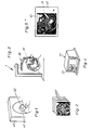
- Figur 1:
- eine schematische Darstellung zur Aufnahme einer Computertomographie;
- Figur 2 :
- die anhand der Computertomographie hergestellten Schichtbildaufnahmen;
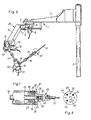
- Figur 3 :
- eine vereinfachte schaubildliche Darstellung einer Koordinatenmeßvorrichtung mit eingesetztem chirurgischem Instrument in Verbindung mit dem zu behandelnden Körperteil eines Patienten;
- Figur 4 :
- einen Computer mit Graphikbildschirm;
- Figur 5 :
- eine erfindungsgemäß aufgearbeitete überlagernde Darstellung des chirurgischen Instrumentes mit einem Schichtbild;
- Figur 6 :
- eine schaubildliche Darstellung der Koordinatenmeßvorrichtung;
- Figur 7 :
- eine Schnittdarstellung einer mit einem Codeabtaster ausgestatteten Kupplung zur Aufnahme eines mit Codezeichen versehenen Instrumententrägers;
- Figur 8 :
- eine Seitenansicht des Instrumententrägers mit Codezeichen;
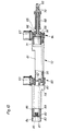
- Figur 9 :
- eine Ansicht eines teilweise dargestellten Gelenkarmes einer zweiten Ausführungsform einer Koordinatenmeßvorrichtung mit einem Gewichtsausgleichsmechanismus;
- Figur 10:
- eine teilweise geschnittene Draufsicht auf den in gestreckter Lage dargestellten Gelenkarm nach Figur 9.
- Figure 1:
- a schematic representation for recording a computed tomography;
- Figure 2:
- the slice images taken on the basis of computer tomography;
- Figure 3:
- a simplified diagrammatic representation of a coordinate measuring device with inserted surgical instrument in connection with the body part of a patient to be treated;
- Figure 4:
- a computer with a graphics screen;
- Figure 5:
- an overlaid representation of the surgical instrument, processed according to the invention, with a slice image;
- Figure 6:
- a perspective view of the coordinate measuring device;
- Figure 7:
- a sectional view of a coupling equipped with a code scanner for receiving an instrument carrier provided with code symbol;
- Figure 8:
- a side view of the instrument carrier with code sign;
- Figure 9:
- a view of a partially shown articulated arm of a second embodiment of a coordinate measuring device with a weight compensation mechanism;
- Figure 10:
- 9 shows a partially sectioned top view of the articulated arm shown in the extended position according to FIG. 9.
In Figur 3 ist eine vereinfacht dargestellte Koordinatenmeßvorrichtung (1) gezeigt, deren konstruktiver Aufbau aus Figur 6 hervorgeht. Die Koordinatenmeßvorrichtung (1) hat einen auf einer Stange (2) einstellbaren Ausleger (3). Der Ausleger (3) ist über ein Gelenk (4) mit einem in horizontaler Ebene verschwenkbaren Arm (5) verbunden. Am Gelenk (4) ist ein Drehmelder (6) angeordnet, der ein der jeweiligen Winkelstellung des Armes (5) entsprechendes Signal abgibt.In Figure 3 is a simplified coordinate measuring device (1) shown its constructive Structure shown in Figure 6. The coordinate measuring device (1) has one on a pole (2) adjustable boom (3). The boom (3) is via a joint (4) with one in a horizontal plane pivotable arm (5) connected. On the joint (4) a resolver (6) is arranged, the one corresponding to the respective angular position of the arm (5) Emits signal.
Am Arm (5) ist über ein Gelenk (7) ein in vertikaler Ebene schwenkbarer Arm (8) gelagert, dessen Winkelstellung durch einen Drehmelder (9) erfaßt wird. Am anderen gabelförmig ausgebildeten Ende des Armes (8) ist mittels eines Gelenkes (10) eine Trägerstange (11) schwenkbar angeordnet, deren Schwenklage durch einen Drehmelder (12) erfaßt wird. Die Trägerstange (11) ist ferner über ein Gelenk (13) um ihre Längsachse drehbar. Die Drehlage der Trägerstange (11) wird durch einen Drehmelder (14) erfaßt.On the arm (5) is in via a joint (7) pivotable arm (8) mounted in a vertical plane, its angular position by a resolver (9) is detected. On the other, fork-shaped The end of the arm (8) is by means of a joint (10) a support rod (11) is pivotably arranged, their swivel position by a resolver (12) is detected. The support rod (11) is also over a joint (13) rotatable about its longitudinal axis. The Rotational position of the support rod (11) is determined by a The resolver (14) is detected.
Am anderen gabelförmig ausgebildeten Ende der Trägerstange (11) ist mittels eines Gelenkes (15) eine zweite Trägerstange (16) schwenkbar angeordnet, deren Schwenklage durch einen Drehmelder (17) erfaßt wird. Die Trägerstange (16) ist ferner über ein Gelenk (18) um ihre Längsachse drehbar. Die Drehlage der Trägerstange (16) wird durch einen Drehmelder (19) erfaßt.At the other fork-shaped end the support rod (11) is by means of a joint (15) a second support rod (16) is pivotably arranged, their swivel position by a resolver (17) is detected. The support rod (16) is also via a joint (18) about its longitudinal axis rotatable. The rotational position of the support rod (16) is detected by a resolver (19).
Die Bauelemente (3) bis (19) bilden einen Gelenkarm (20) mit sechs Drehachsen.The components (3) to (19) form an articulated arm (20) with six axes of rotation.
Die Gelenke (4), (7), (10), (13), (15), (18) sind so ausgebildet, daß sie selbsthemmend sind, jedoch mit geringem Kraftaufwand bewegt werden können. Bei den Drehmeldern (6), (9), (12), (14), (17), (19) handelt es sich um inkrementale Drehmelder mit 4.000 Impulsen pro Umdrehung. Aufgrund dieser großen Impulszahl ergibt sich eine sehr genaue Winkelerfassung der Schwenk- und/oder Drehstellung der betreffenden Glieder des Gelenkarmes (20). Die Drehmelder (6), (9), (12), (14), (17), (19) sind über nicht bezeichnete Kabel mit einem in Figur 4 schaubildlich dargestellten Datenverarbeitungssystem (21) verbunden, das einen Computer, einen Datenspeicher und als Ausgabegerät einen Bildschirm (22) umfaßt.The joints (4), (7), (10), (13), (15), (18) are designed to be self-locking, however can be moved with little effort can. For the resolvers (6), (9), (12), (14), (17), (19) are incremental resolvers with 4,000 pulses per revolution. by virtue of this large number of impulses results in a very precise angle detection of the swivel and / or rotational position of the relevant members of the Articulated arm (20). The resolvers (6), (9), (12), (14), (17), (19) are via unmarked cables with a diagram shown in Figure 4 Data processing system (21) connected, the one Computer, a data storage and as an output device comprises a screen (22).
Auf der Trägerstange (16) ist im Bereich ihres freien Endes ein Flansch (23) befestigt, dessen Umfangsseite durch eine Hülse (24) abgedeckt ist. An der Trägerstange (16) ist im Anschluß an den Flansch (23) ein einseitig abgeflachter Zapfen (25) ausgebildet. In einer quer verlaufenden Sackbohrung (26) des Zapfens (25) ist eine federbelastete Kugel (27) angeordnet, die durch eine entsprechende nicht dargestellte Verengung am Rand der Bohrung (26) gegen Herausfallen gesichert ist.On the support rod (16) is in the area of free end a flange (23) attached, the Circumferential side is covered by a sleeve (24). On the support rod (16) is following the Flange (23) a pin flattened on one side (25) educated. In a transverse blind hole (26) of the pin (25) is a spring-loaded Ball (27) arranged by a corresponding Not shown narrowing at the edge of the hole (26) is secured against falling out.
Auf dem Zapfen (25) ist ein Instrumententräger (28) aufgesteckt, der eine der Kugel (27) zugeordnete und mit dieser ein Rastgesperre bildende Vertiefung (29) aufweist. Der Träger (28) enthält eine der Form des abgeflachten Zapfens (25) entsprechend ausgebildete Bohrung (30), wodurch der Träger (28) gegen Verdrehen gesichert ist. Im Träger (28) ist ein chirurgisches Instrument (31) lösbar befestigt. Somit bilden der Träger (28) und der Zapfen (25) eine Kupplung (32) zum Verbinden des chirurgischen Instrumentes (31) mit dem Gelenkarm (20) der Koordinatenmeßvorrichtung (1), die somit zugleich eine Führungs- und Haltevorrichtung für das Instrument (31) bildet.On the pin (25) is an instrument holder (28) attached, one of the ball (27) assigned and with this recess forming a locking mechanism (29). The carrier (28) contains one corresponding to the shape of the flattened pin (25) trained bore (30), whereby the Carrier (28) is secured against twisting. In the carrier (28) a surgical instrument (31) can be released attached. Thus, the carrier (28) and the Pin (25) a coupling (32) for connecting the surgical instrument (31) with the articulated arm (20) the coordinate measuring device (1), the thus a guide and holding device at the same time for the instrument (31).
An der Stirnfläche eines Flanschteiles des Instrumententrägers (28) sind mehrere kreisförmig angeordnete Sackbohrungen (33) vorgesehen, in denen drei Permanentmagnete (34) befestigt sind. Die Anordnung der Permanentmagnete (34) bildet einen dem eingesetzten Instrument (31) zugeordneten Kennzeichencode.On the face of a flange part of the instrument holder (28) are several circular arranged blind bores (33) provided in which three permanent magnets (34) are attached. The arrangement of the permanent magnets (34) forms one assigned to the instrument (31) used Identification Code.
Im Flansch (23) sind eine der Anzahl der Sackbohrungen (33) entsprechende Anzahl von Hallgeneratoren (35) angeordnet, die den Bohrungen (33) bzw. den in diesen eingesetzten Permanentmagneten (34) genau gegenüberliegen und einen Codeabtaster (36) bilden. Die Permanentmagnete (34) bewirken, daß die ihnen zugeordneten Hallgeneratoren (35) ein Signal erzeugen. Die von den Hallgeneratoren (35) bzw. dem Codeabtaster (36) erzeugten Signale werden dem Datenverarbeitungssystem (21) zugeführt, wodurch dieses über die Art und Größe des mit dem Gelenkarm (20) verbundenen chirurgischen Instrumentes (31) informiert wird.In the flange (23) are one of the number of blind holes (33) corresponding number of Hall generators (35) arranged which the bores (33) or the permanent magnets used in these (34) exactly opposite and a code scanner (36) form. Permanent magnets (34) cause the Hall generators assigned to them (35) generate a signal. The Hall generators (35) or the code scanner (36) Signals are sent to the data processing system (21) supplied, which this on the type and Size of the connected to the articulated arm (20) surgical instrument (31) is informed.
Die in Fig. 9 teilweise dargestellte Koordinatenmeßvorrichtung (50) weist einen an einer nicht dargestellten Stange einstellbar angeordneten Ausleger (51) auf. Auf dem Ausleger (51) ist ein flanschartiges Gelenkteil (52) befestigt, in dem ein hohler Gelenkbolzen (53) drehbar gelagert ist. Am unteren Ende des Gelenkbolzens (53) ist eine quer abstehende Trägerplatte (54) ausgebildet. Auf einem über das Gelenkteil (52) hinausragenden Abschnitt des Gelenkbolzens (53) ist ein Stellring (55) festgeklemmt, der gemeinsam mit der Trägerplatte (54) den Gelenkbolzen (53) axial sichert.The coordinate measuring device partially shown in FIG. 9 (50) has one on a not shown Adjustable boom (51). On the boom (51) is a flange Fixed hinge part (52) in which a hollow Hinge pin (53) is rotatably mounted. At the bottom The end of the hinge pin (53) is a protruding one Carrier plate (54) formed. On one section projecting beyond the joint part (52) an adjusting ring (55) is clamped on the pivot pin (53), which together with the carrier plate (54) axially secures the hinge pin (53).
An der Trägerplatte (54) ist ein quer abstehender hohler Arm (56) befestigt. Am Arm (56) ist ein koaxial zum Gelenkbolzen (53) verlaufender Zapfen (57) befestigt, der die Drehstellung des Armes (56) auf einen Drehmelder (58) überträgt, welcher über eine Halterung (59) an dem Ausleger (51) verdrehsicher angeordnet ist.On the support plate (54) is a transversely protruding hollow arm (56) attached. On the arm (56) is a Pin extending coaxially to the hinge pin (53) (57) attached to the rotational position of the arm (56) transmits to a resolver (58), which via a bracket (59) on the boom (51) against rotation is arranged.
Am Arm (56) ist über ein Gelenk (60) ein in vertikaler Ebene schwenkbarer, hohl ausgebildeter Arm (61) gelagert, dessen Winkelstellung über einen Gelenkbolzen (62) auf einen mit dem Arm (56) verbundenen Drehmelder (63) übertragen wird. Am anderen Ende des Armes (61) ist mittels eines Gelenkes (64) eine hohl ausgebildete Trägerstange (65) schwenkbar gelagert, deren Schwenklage über einen von zwei miteinander fluchtenden Gelenkbolzen (66) (Fig. 10) auf einen am Arm (61) angeordneten Drehmelder (67) übertragen wird. Auf der Trägerstange (65) ist eine Hülse (68) drehbar gelagert, die mit einer zweiten Trägerstange (69) (Fig. 10) drehfest verbunden ist. Die Drehlage der zweiten Trägerstange (69) gegenüber der ersten Trägerstange (65) wird über eine Welle (70) auf einen an der Trägerstange (65) angeordneten Drehmelder (71) übertragen.On the arm (56) is an in via a joint (60) vertical level swiveling, hollow Arm (61) mounted, the angular position over a Hinge pin (62) on one with the arm (56) connected resolver (63) is transmitted. At the other end of the arm (61) is by means of a Joint (64) a hollow support rod (65) pivotally mounted, the pivot position of one of two pivot pins aligned with each other (66) (Fig. 10) on one arranged on the arm (61) The resolver (67) is transmitted. On the Carrier rod (65) has a sleeve (68) rotatably mounted, which with a second support rod (69) (Fig. 10) is non-rotatably connected. The rotational position of the second Carrier rod (69) opposite the first carrier rod (65) is on a shaft (70) on the support rod (65) arranged resolver (71) transferred.
Die Bauelemente (51 bis 71) sind Bestandteile eines Gelenkarmes (72), der ähnlich wie der Gelenkarm (20) (Fig. 6) aufgebaut ist und somit außer diesen Bauelementen noch eine weitere nicht dargestellte quer und längs drehbare Trägerstange aufweist. Der Gelenkarm (72) hat auf diese Weise wie der Gelenkarm (20) sechs Drehachsen. An der nicht dargestellten Trägerstange ist über eine der Kupplung (32) entsprechende nicht dargestellte Kupplung ein gleichfalls nicht dargestellter Instrumententräger angeschlosen, der wie der Instrumententräger (28) aufgebaut ist.The components (51 to 71) are components an articulated arm (72) which is similar to the articulated arm (20) (Fig. 6) is constructed and thus except these components still another, not shown support bar rotatable crosswise and lengthwise having. The articulated arm (72) has in this way like the articulated arm (20) six axes of rotation. At the support rod, not shown, is over one of the Coupling (32) corresponding not shown Coupling an instrument carrier, also not shown connected, like the instrument holder (28) is constructed.
Der Gelenkarm (72) ist mit einem Gewichtsausgleichsmechanismus (73) versehen. Dieser weist einen auf dem oberen Ende des Gelenkbolzens (53) aufgeklemmten, gabelförmig ausgebildeten Träger (74) auf, der an seinem oberen Ende einen feststehenden Bolzen (75) enthält. Auf dem Bolzen (75) sind zwei Zahnriemenräder (76, 77) unabhängig voneinander frei drehbar gelagert. Mit dem vorderen Zahnriemenrad (76) ist eine Stange (78) fest verbunden, an deren Ende eine Ausgleichsmasse (79) angeordnet ist. Mit dem hinteren Zahnriemenrad (77) ist eine längere Stange (80) fest verbunden, an deren Ende eine Ausgleichsmasse (81) angeordnet ist.The articulated arm (72) is with a weight balancing mechanism (73). This points one on the top end of the hinge pin (53) clamped, fork-shaped Carrier (74) on one at its upper end contains fixed bolt (75). On the bolt (75) two toothed belt wheels (76, 77) are independent freely rotatable from each other. With the front toothed belt wheel (76) is a rod (78) firmly connected, at the end of a leveling compound (79) is arranged. With the rear toothed belt wheel (77) is a longer rod (80) fixed connected, at the end of a balancing mass (81) is arranged.
Im Arm (56) ist ein parallel zum Bolzen (75) verlaufender Bolzen (82) fest angeordnet, auf dem zwei unabhängig voneinander frei drehbare Doppelzahnriemenräder (83, 84) gelagert sind. Das hintere Zahnriemenrad (77) und das innere Rad des hinteren Doppelzahnriemenrades (84) sind durch einen Zahnriemen (85) miteinander verbunden. Das äußere Rad des hinteren Doppelzahnriemenrades (84) ist über einen Zahnriemen (86) mit einem nicht dargestellten Zahnriemenrad verbunden, das auf dem Gelenkbolzen (62) angeordnet und mit dem Arm (61) drehfest verbunden ist. Aufgrund dieser Konstruktion werden Schwenkbewegungen des Armes (61) über die beiden Zahnriemen (86 und 85) auf das hintere Zahnriemenrad (77) übertragen, wodurch die Stange (80) mit der Ausgleichsmasse (81) im gleichen Drehsinn verschwenkt wird. Bei sich horizontal erstreckendem Arm (61) nimmt die Stange (80) eine im wesentlichen ebenfalls horizontale Lage ein und bei sich vertikal erstreckendem Arm (61) eine im wesentlichen ebenfalls vertikale Lage. Dabei sind die Ausrichtlagen von Arm (61) und Stange (80) einander entgegengesetzt, d. h., daß sich die Stange (80) in abgesenkter Stellung befindet, wenn der Arm (61) angehoben ist und umgekehrt. Bei einer die Gewichtskraft des Armes (61) und der von ihm getragenen weiteren Bauelemente des Gelenkarmes (72) berücksichtigenden Bemessung der Ausgleichsmasse (81) wird von dieser ein Drehmoment erzeugt, das dem von der wirksamen Gewichtskraft des Armes (61) und den von diesem getragenen Bauelementen des Schwenkarmes (72) hervorgerufenen Drehmoment entgegengerichtet ist und aufgrund des Gewichtsausgleichs bewirkt, daß der Arm (61) in den beiden entgegengesetzten Schwenkrichtungen mit weitgehend gleichmäßiger geringer Kraft bewegt werden kann.In the arm (56) is a parallel to the bolt (75) extending bolt (82) fixed on the two independently rotating double toothed belt wheels (83, 84) are stored. The rear Toothed belt wheel (77) and the inner wheel of the rear double toothed belt wheel (84) are through a toothed belt (85) connected together. The outer wheel of the rear double toothed belt wheel (84) is not over a toothed belt (86) with one illustrated toothed belt wheel connected to the the hinge pin (62) arranged and with the Arm (61) is rotatably connected. Based on these Construction are swiveling movements of the arm (61) via the two toothed belts (86 and 85) transferred to the rear toothed belt wheel (77), whereby the rod (80) with the balancing mass (81) is pivoted in the same direction. at horizontally extending arm (61) takes the Rod (80) is also essentially horizontal Position one and with vertically extending Arm (61) is also essentially vertical Location. The alignment positions of arm (61) and rod (80) opposed to each other, i. H., that the rod (80) in the lowered position when the arm (61) is raised and vice versa. The weight of the arm (61) and the other components it supports of the articulated arm (72) Dimensioning of the balancing mass (81) is from This generates a torque that is that of the effective weight of the arm (61) and from this supported components of the Swivel arm (72) produced torque is opposite and due to the weight balance causes the arm (61) in the two opposite pivot directions with largely uniformly small force can be moved can.
Das vordere Zahnriemenrad (76) und das innere Rad des vorderen Doppelzahnriemenrades (83) sind durch einen Zahnriemen (87) miteinander verbunden. Das äußere Rad des vorderen Doppelzahnriemenrades (83) ist über einen Zahnriemen (88) mit einem Rad eines Doppelzahnriemenrades (89) verbunden, das auf dem Gelenkbolzen (62) frei drehbar angeordnet ist. Das andere Rad des Doppelzahnriemenrads (89) ist über einen Zahnriemen (90) mit einem Zahnriemenrad (91) verbunden, das auf dem vorderen Gelenkbolzen (66) angeordnet und mit der Trägerstange (65) drehfest verbunden ist.The front timing belt pulley (76) and the inner one Front Double Timing Belt Pulley Wheel (83) are connected to each other by a toothed belt (87). The outer wheel of the front double toothed belt wheel (83) is over a timing belt (88) with a wheel of a double toothed belt wheel (89) connected, free on the hinge pin (62) is rotatably arranged. The other wheel of the double toothed belt wheel (89) is over a timing belt (90) connected to a toothed belt wheel (91), the arranged on the front hinge pin (66) and rotatably connected to the support rod (65) is.
Durch die Zahnriemen (90, 88 und 87) werden die Schwenkbewegungen der Trägerstange (65) auf das vordere Zahnriemenrad (76) übertragen, wodurch die Stange (78) mit der Ausgleichsmasse (79) im gleichen Drehsinn verschwenkt wird. Hierbei sind die Bewegungsverhältnisse zwischen der Trägerstange (65) und der Ausgleichsmasse (79) vergleichbar den vorstehend beschriebenen Bewegungsverhältnissen zwischen dem Arm (61) und der Ausgleichmasse (81). Bei entsprechender Bemessung der Ausgleichsmasse (79) wird von dieser ein Drehmoment erzeugt, das dem von der wirksamen Gewichtskraft der Trägerstangen (65, 69), der Hülse (68) und den von der Trägerstange (69) getragenen Bauelementen des Gelenkarmes (72) hervorgerufenen Drehmoment entgegengerichtet ist. Aufgrund dieses Gewichtsausgleiches können die Trägerstangen (65, 69) und die Hülse (68) bei ihren Schwenkbewegungen um die Gelenkbolzen (66) mit weitgehend gleichmäßiger geringer Kraft bewegt werden.Through the timing belt (90, 88 and 87) the pivoting movements of the support rod (65) transferred to the front toothed belt wheel (76), whereby the rod (78) with the balancing mass (79) is pivoted in the same direction. in this connection are the movement relationships between the Carrier rod (65) and the balancing mass (79) comparable to the movement conditions described above between the arm (61) and the balancing mass (81). With appropriate dimensioning the balancing mass (79) is from this generates a torque that is that of the effective Weight force of the support rods (65, 69), the Sleeve (68) and that of the support rod (69) supported components of the articulated arm (72) caused torque directed is. Because of this weight balance the support rods (65, 69) and the sleeve (68) their pivoting movements around the hinge pins (66) with largely uniform, low force be moved.
Auf dem Stellring (55) ist ein zweiteiliges geschlossenes Gehäuse (92) aufgeklemmt, das die Bewegungsbahnen der Ausgleichsmassen (79, 81) umschließt.On the collar (55) is a two-part closed Clamped housing (92) that the Paths of movement of the balancing masses (79, 81) encloses.
In einer weiteren, nicht dargestellten Ausführungsform eines Gelenkarmes sind die sechs Drehmelder gemeinsam in einem dem Gehäuse (92) vergleichbaren Gehäuse untergebracht, wobei die einzelnen Drehmelder über jeweils eigene Zahnriemen- oder Zahnradgetriebe mit den einzelnen Gliedern des Gelenkarmes verbunden sind. Durch diese Maßnahme ist der Gelenkarm nicht nur masseärmer und dadurch leichter handhabbar, sondern er ist auch schlanker wodurch die Kollisionsgefahr verringert wird.In a further embodiment, not shown the six resolvers of an articulated arm together in one the housing (92) comparable housing, the individual resolvers each with their own Toothed belt or gear transmission with the individual Limbs of the articulated arm are connected. By this measure, the articulated arm is not only low mass and therefore easier to handle, but it is also slimmer which reduces the risk of collision is reduced.
Die Funktionsweise der Vorrichtung werden nachfolgend anhand eines typischen Ablaufes näher erläutert.The functioning of the device are based below of a typical process explained in more detail.
Zunächst wird eine zu behandelnde Person (wie in Figur 1 dargestellt) zur Aufnahme mehrerer Schichtbilder in ein geeignetes Schichtbild-Aufnahmegerät (40) geschoben. Beispielsweise können hier Computertomographie-Aufnahmen oder beispielsweise Kernspintomographien hergestellt werden.First, a person to be treated (as shown in Figure 1) to accommodate several Layer images in a suitable layer image recording device (40) pushed. For example here computer tomography recordings or for example Magnetic resonance imaging can be produced.
In Figur 2 sind schematisch die entsprechend gemäß Figur 1 aufgenommenen Schichtaufnahmen (41) dargestellt.In Figure 2 are the corresponding schematically slice images taken in accordance with FIG. 1 (41).
Vor der Aufnahme sind in dem interessierenden Bereich einer zu operierenden Person drei Meßpunkte (42) markiert, befestigt, ausgemessen oder festgelegt, von denen zwei im Bereich der Ohren liegen, während der dritte beispielsweise durch den unten auslaufenden Spalt zwischen den beiden oberen Schneidezähnen gebildet sein kann.Before recording are in the interested Area of a person to be operated on three Measuring points (42) marked, fastened, measured or set, two of which are in the field of Ears lie while the third, for example through the gap between the two upper incisors can be formed.
Sofern aufgrund der tatsächlichen Verhältnisse nicht bestimmte Meßpunkte festgelegt werden können, so können auch beispielsweise kleine Keramikteilchen an vorbestimmten Stellen als Meßpunkt eingesetzt und angebracht werden. Keramikteilchen eignen sich insbesondere, weil diese bei den entsprechenden Aufnahmen keine Reflektion hervorrufen.If based on the actual circumstances specific measuring points cannot be determined, for example, small ceramic particles at predetermined points as a measuring point used and attached. ceramic are particularly suitable because they are used in the corresponding Recordings do not cause reflection.
Die erwähnten Meßpunkte (42) sind auf den in Figur 2 wiedergegebenen Schichtaufnahmen (41) an der jeweils betreffenden Stelle bzw. Lage abgebildet und von den Daten her mitumfaßt. Die mit den Daten der Meßpunkte versehenen Schichtbilddaten, die in ihrer Gesamtheit eine räumliche Struktur des zu behandelnden Körperteils wiedergeben, werden in einem entsprechenden Speicher des Datenverarbeitungssystems abgespeichert.The measuring points (42) mentioned are on the in Figure 2 reproduced slice images (41) depicted at the relevant point or location and included from the data. With the data of the measuring point provided slice image data, which in its entirety is spatial Reproduce the structure of the body part to be treated, are in an appropriate store of the data processing system.
Zur Vorbereitung einer durchzuführenden Operation wird der Patient auf einem Operationstisch liegend gehalten und justiert. Vor Durchführung der Operation wird zunächst über die erwähnte Koordinatenmeßvorrichtung (1) die Lage der drei am Patienten angebrachten und befestigten bzw. festgelegten Meßpunkte (42) festgestellt. Dies geschieht in der Weise, daß das chirurgische Instrument (31) oder ein stattdessen verwendeter Taster mit den Meßpunkten (42) in Berührung gebracht wird, wobei das Instrument oder der Taster aufgrund der Gelenkigkeit des Gelenkarmes (20) völlig unbehindert angehoben, abgesenkt, geneigt, winkelig verstellt und vorgeschoben werden kann. Jede Bewegung und Lage der einzelnen Glieder des Gelenkarmes (20) wird über die Drehmelder (6), (9), (12), (14), (17), (19) exakt erfaßt und dem Datenverarbeitungssystem (21) übermittelt. Die auf diese Weise gewonnenen Lagedaten der Meßpunkte (42) werden mit den Bilddaten der Meßpunkte (42) im Datenspeicher (7) überprüft. Durch entsprechende Berechnung des Computers werden die am Operationstisch in ihrer Lage festgestellten Meßpunkte (42) so in Übereinstimmung mit den abgespeicherten Bilddaten der Meßpunkte (42) gebracht, daß nunmehr eine exakte Zuordnung der abgespeicherten Schichtaufnahmedaten mit der konkreten räumlichen Lage des Patienten und v. a. des chirurgischen Instrumentes (31) vorgenommen wird.To prepare for an operation to be performed the patient is on an operating table kept lying and adjusted. Before performing the The operation is first carried out using the coordinate measuring device mentioned (1) the location of the three on the patient attached and fixed or fixed Measuring points (42) determined. this happens in such a way that the surgical instrument (31) or a button used instead with the Measuring points (42) is brought into contact, wherein the instrument or the button due to the Articulation of the articulated arm (20) completely unimpeded raised, lowered, inclined, angularly adjusted and can be advanced. Every movement and position of the individual links of the articulated arm (20) is via the resolver (6), (9), (12), (14), (17), (19) exactly recorded and the data processing system (21) transmitted. That way obtained location data of the measuring points (42) with the image data of the measuring points (42) in the data memory (7) checked. By appropriate Calculation of the computer will be done at the operating table measuring points determined in their position (42) so in accordance with the stored Image data of the measuring points (42) brought that now an exact assignment of the stored Layer acquisition data with the concrete spatial Position of the patient and v. a. of the surgical Instrumentes (31) is made.
Mit Hilfe der vom Codeabtaster (36) übermittelten Signale ruft der Computer dem entsprechenden chirurgischen Instrument (31) zugeordnete, im Datenspeicher abgelegte Kennzeichenwerte über die Größe und die Entfernung der Instrumentenspitze vom Instrumententräger (28) ab, wodurch bei jedem der verschiedenen Instrumente bei einer beliebigen Stellung des Instrumententrägers (28) durch den Computer die genaue Lage der Instrumentenspitze berechnet wird.With the help of those transmitted by the code scanner (36) The computer calls the appropriate signals associated surgical instrument (31), in the data memory stored license plate values via the Size and distance of the instrument tip from the instrument carrier (28), whereby each of the various instruments in any Position of the instrument holder (28) the exact position of the instrument tip through the computer is calculated.
Nachdem über die Koordinatenmeßvorrichtung (1) die drei Meßpunkte (42) angefahren und dadurch die exakte, räumliche Zuordnung zwischen chirurgischem Instrument (31) und Patient in Übereinstimmung mit den gespeicherten Schichtaufnahmen (41) hergestellt worden ist, kann mit der Operation begonnen werden, so daß nunmehr bei einer Bewegung und einem entsprechenden Eingriff die Spitze bzw. der wirksame Bereich des chirurgischen Instrumentes über die Koordinatenmeßvorrichtung (1) bei jeder auch noch so kleinen Bewegung oder/und Winkelbewegung erfaßt und mittels des Computers festgestellt werden kann. Diese erfaßte Bewegung des chirurgischen Instrumentes wird dann über den Computer auf dem Bildschirm (22), gemeinsam mit der jeweils aktuellen Schichtbildaufnahme abgebildet, wodurch ein Überlagerungsbild (43) entsteht.After about the coordinate measuring device (1) approached the three measuring points (42) and thereby the exact spatial allocation between surgical instrument (31) and patient in agreement with the saved slice images (41) can be made with surgery be started, so that now at one Movement and a corresponding intervention the Tip or the effective area of surgical Instrumentes over the coordinate measuring device (1) with every little movement or / and angular movement detected and by means of of the computer can be determined. This captured Movement of the surgical instrument is then displayed on the computer via the computer (22), together with the current layer image recording mapped, creating an overlay image (43) arises.
Die Bilddaten der Überlagerungsbilder (43) werden zur Dokumentation des Ablaufes des chirurgischen Eingriffes im Datenspeicher abgelegt, aus dem sie jederzeit wieder abrufbar und erneut auf dem Bildschirm (22) darstellbar sind.The image data of the overlay images (43) are used to document the surgical process Intervention stored in the data memory, from which they can be called up again at any time and again can be displayed on the screen (22).
Sobald sich bei jedem weiteren Verschieben, Eindringen oder Verdrehen des chirurgischen Instrumentes die Instrumentenspitze aus der momentan auf dem Bildschirm (22) dargestellten Schichtaufnahme herausbewegt, wird anstelle dieser Aufnahme automatisch diejenige Schichtaufnahme abgebildet, in die sich die Instrumentenspitze nunmehr hineinbewegt. Dadurch wird für einen Operateur die maximale Information darüber vermittelt, in welchem exakten Bereich er sich während der Operation befindet.As soon as each subsequent move Penetration or twisting of the surgical instrument the instrument tip from the moment layer image shown on the screen (22) is moved out instead of this shot that layer image is automatically mapped, in which the instrument tip now inside moves. This is for an operator the maximum information conveyed in what exact range it is during the Surgery.
Eine weitere Maßnahme zur besseren Information über die räumliche Stellung der Instrumentenspitze innerhalb des Operationsgebietes läßt sich dadurch erreichen, daß in verschiedenen Fenstern des Bildschirmes (22) gleichzeitig Überlagerungsbilder dargestellt werden, die von längs, quer und horizontal verlaufenden Schichtaufnahmen gebildet wurden.Another measure for better information about the spatial position of the instrument tip within the operating area by doing that in different windows the screen (22) simultaneously overlay images are represented by longitudinal, transverse and horizontal slice images formed were.
Die Hilfe durch die geschilderte Vorrichtung kann noch dadurch erhöht werden, daß beispielsweise je nach Bedarf eine der jeweils weiter tiefer liegenden nächsten Schichten vorab auf dem Bildschirm (22) dargestellt werden kann, um schon vorher zu überlegen, in welcher Richtung nachfolgend das chirurgische Instrument (31) weiter fortbewegt werden soll. Auch hierdurch wird die Sicherheit gegenüber herkömmlichen Verfahren und Vorrichtungen erheblich verbessert.The help through the described device can be increased, for example, that depending on the need one of the further deeper lying next layers in advance on the screen (22) can already be represented to think in advance in which direction the surgical instrument (31) continues to move shall be. This also increases security compared to conventional processes and Devices significantly improved.
Die geschilderte Koordinatenmeßvorrichtung (1) dient also im vorliegenden Fall nicht nur zur Positionserfassung des Operations-Instrumententrägers (28) bzw. des Instrumentes (31) selbst, sondern auch zur Erfassung der drei Meßpunkte (42). Dies bietet den weiteren Vorteil, daß auch während der Operation jederzeit überprüft werden kann, ob die exakte Lage des Patienten beibehalten worden ist. Dazu müssen lediglich über ein Instrument die drei Meßpunkte (42) auch während der Operation abgefahren und die entsprechenden Lagedaten jeweils in den Computer eingegeben werden. Sollte eine leichte Lageveränderung des zu behandelnden Körperteiles festgestellt worden sein, so kann diese Lageveränderung sofort rechnerisch erfaßt und das auf dem Bildschirm (22) dargestellte Bild korrigiert werden.The coordinate measuring device described (1) is therefore not only used for position detection in the present case of the surgical instrument holder (28) or the instrument (31) itself, but also for recording the three measuring points (42). This offers the further advantage that even during the Operation can be checked at any time whether the exact position of the patient has been maintained. To do this, the three only have to have one instrument Measuring points (42) also traversed during the operation and the corresponding location data in each case entered into the computer. Should one slight change in the position of the patient to be treated Part of the body has been determined, this can Change in position immediately calculated and that Corrected image displayed on the screen (22) become.
Im gezeigten Ausführungsbeispiel ist das chirurgische Instrument der Koordinatenmeßvorrichtung (1) am Gelenkarm (20) lösbar angebracht bzw. mit diesem verbunden. Möglich ist aber genauso, daß das chirurgische Instrument kontaktlos über eine "Ortungsvorrichtung", also eine Koordinatenmeßvorrichtung ständig überwacht wird und dadurch die exakten Lagekoordinaten der Spitze bzw. des wirksamen Bereiches des Instrumentes festgestellt und an den Computer weitergeleitet werden. Dies kann durch beispielsweise drei räumlich angeordnete Sonden und drei Detektoren erfolgen.In the exemplary embodiment shown, this is surgical Instrument of the coordinate measuring device (1) detachably attached to the articulated arm (20) or connected to it. But it is also possible that the surgical instrument is contactless via a "locating device", ie a coordinate measuring device is constantly monitored and thereby the exact position coordinates of the tip or the effective area of the instrument detected and forwarded to the computer become. This can be done spatially by, for example, three arranged probes and three detectors.
Ob dabei die Lagekoordinaten-Feststellung aufgrund eines akustischen oder optischen oder elektromagnetischen Weges erfolgt (z. B. oberhalb oder unterhalb des Lichtwellenbereiches), hängt vom Einzelfall ab.Whether the determination of the position coordinates is due to this an acoustic or optical or electromagnetic Way (e.g. above or below the light wave range) depending on the individual case.
Werden mit dem chirurgischen Instrument bestimmte Körperteile entfernt, so können durch Abfahren der dabei entstandenen Höhlungen in Form einer Hüllkurve die so gewonnenen Daten während der Operation in den Datenspeicher eingegeben und dementsprechend die vor der Operation gewonnenen Schichtbilddaten modifiziert werden. Damit lassen sich auf dem Bildschirm (22) die aktuellen, während der Operation geänderten Verhältnisse darstellen. Die auf diese Weise gewonnenen postoperativen Schichtbilder werden ferner zur Dokumentation des Operationsergebnisses im Datenspeicher abgelegt.Are determined with the surgical instrument Body parts removed, so can by driving the resulting cavities in the form the data thus obtained during an envelope curve the operation entered in the data memory and accordingly those obtained before the operation Layer image data are modified. In order to the current, conditions changed during the operation represent. The so obtained Postoperative slices are also used for documentation of the operation result in the data storage stored.
Claims (8)
- Device for carrying out a technique for reproducible optical representation of an operation carried out with a surgical instrument (31) in which operationwhereintomographic information of a body part in which the surgical operation is to be carried out is stored in the data memory of a data processing system (21),positional data of an operating site are determined by the tomographic information,the surgical instrument (31) is mounted on a three-dimensionally freely movable carrier (16),attitude data of the surgical instrument (31) are determined by a co-ordinate measuring device (1;50) and fed to the data processing system (21) which relates the attitude data of the surgical instrument (31) to the positional data of the operation site, andthe surgical instrument (31) is aligned with respect to the operating site on the basis of this relationship,at least three measurement points (42) accessible from outside are determined or arranged as reference points on the body part,tomograms (41) of the body part which contain the measurement points (42) are produced and filed in the data memory,the spatial position of the measurement points (42) is measured by the co-ordinate measuring device (1;50) and the measurement data are filed in the data memory,the data processing system (21) produces a relationship between the image data contained in the tomograms (41) of the measurement points (42) and the data determined by the co-ordinate measuring device (1;50) of the measurement points (42),the spatial attitude of the three-dimensionally freely movable surgical instrument (31) is continuously measured within the body part with the aid of the co-ordinate measuring device (1;50) and the attitude data are fed to the data processing system (21), andthe data processing system (21) superimposes the attitude data of the surgical instrument (31) on the image information of the tomograms andthe data processing system (21) generates on an output device, in particular a display screen (22), superimposition images (43) in which the image contents of the tomograms (41) and the respective attitudes of the surgical instrument (31) are superimposed on one another,the device includes:a data processing system (21),a data memory in the data processing system (21) in which tomogram information of a body part in the form of a series of tomograms (41) is stored,a display screen (22) connected with the data processing system (21) for displaying selected tomograms (41) of the tomogram information,a three-dimensionally freely movable carrier (16) which carries a surgical instrument (31),a co-ordinate measuring device (1;50) coupled with the carrier (16) and the data processing system (21) for determining the attitude data of the surgical instrument (31) which data are relatable to attitude data in the tomogram information by means of the data processing system (21),at least three determined measurement points (42) on the body accessible from outside,tomogram information in which the measurement points (42) are contained,a means in the data processing system (21) for producing a relationship between the positional data of the measurement points (42) scanned by the co-ordinate measuring device (1,50) in the tomogram information and thus generally between positional data of the tomogram information and the attitude data of the surgical instrument (31) determined by the co-ordinate measuring device (1;50),a means in the data processing system (21) for superimposing on the tomogram information the attitude data of the surgical instrument (31) ascertained during the surgical operation in the body part due to said relationship, and for producing superimposition images (43),a means connected with the data processing system (21) for continuous reproduction of the superimposition images (43) on the display screen (22) which show continuously the positions of the surgical instrument in the tomograms (41),a means connected with the data processing system (21) for substituting on the display screen (22) that tomogram (41) in which the surgical instrument (31) is located in a given moment with the tomogram (41) situated next to it when the surgical instrument (31) has moved from the area of this tomogram (41) to the area of the neighbouring tomogram (41).a means in the data processing system (21) for comparing the momentary positional data of the measurement points (42) determined at time intervals by the co-ordinate measuring device (1;50) with the original positional data of the measurement points (42) and carrying out correction of the position of the tomograms (41) displayed on the output device when divergencies occur.
- Device according to Claim 1, characterised in that the carrier (16) of the surgical instrument (31) is mounted on a three-dimensionally freely movable articulated arm (20; 72), and the coordinate measuring device (1;50) has synchros connected to the articulated arm (20; 72).
- Device according to Claim 1, characterised in that the coordinate measuring device is constructed as a locator with contactless determination of the attitude data of the surgical instrument (31).
- Device according to Claim 2, characterised in that the articulated arm (20; 72) contains six axes of rotation.
- Device according to Claim 4, characterised in that the articulated arm (72) has a balancing mechanism (73).
- Device according to Claim 5, characterised in that two members (61; 65, 68, 69) of the articulated arm (72) that can be pivoted about horizontal axes (62; 66) are connected via toothed belt drives (85, 86; 87, 88, 90) to their own counterweights (79, 81) in each case.
- Device according to one or more of Claims 1 to 6 characterised in that the surgical instruments (31) and/or the probe can be connected via a coupling (32) to the coordinate measuring device (1; 50) and are provided with an identification code (34) and in that a code scanner (36) which is connected for the purpose of reproducing the code information to the data processing system (21) is arranged in the region of the coupling (32).
- Device according to one or more of Claims 1 and 4 to 7, characterised in that the measuring instruments of the coordinate measuring device (1; 50) that are assigned to the individual articulations are arranged in a central housing and connected to the articulations by flexible drives and gear trains.
Priority Applications (1)
| Application Number | Priority Date | Filing Date | Title |
|---|---|---|---|
| AT88904956T ATE95402T1 (en) | 1987-05-27 | 1988-05-21 | METHOD AND DEVICE FOR THE REPRODUCIBLE OPTICAL REPRESENTATION OF A SURGICAL INTERVENTION. |
Applications Claiming Priority (4)
| Application Number | Priority Date | Filing Date | Title |
|---|---|---|---|
| DE3717871A DE3717871C3 (en) | 1987-05-27 | 1987-05-27 | Method and device for reproducible visual representation of a surgical intervention |
| DE3717871 | 1987-05-27 | ||
| PCT/EP1988/000457 WO1988009151A1 (en) | 1987-05-27 | 1988-05-21 | Process and device for optical representation of surgical operations |
| CA0616958A CA1336923E (en) | 1987-05-27 | 1995-01-10 | Procedure and Apparatus for the Reproducible Representation of a Surgical Operation |
Publications (3)
| Publication Number | Publication Date |
|---|---|
| EP0359773A1 EP0359773A1 (en) | 1990-03-28 |
| EP0359773B1 EP0359773B1 (en) | 1993-10-06 |
| EP0359773B2 true EP0359773B2 (en) | 2002-12-18 |
Family
ID=25673253
Family Applications (1)
| Application Number | Title | Priority Date | Filing Date |
|---|---|---|---|
| EP88904956A Expired - Lifetime EP0359773B2 (en) | 1987-05-27 | 1988-05-21 | device for optical representation of surgical operations |
Country Status (5)
| Country | Link |
|---|---|
| US (1) | US5186174A (en) |
| EP (1) | EP0359773B2 (en) |
| AU (1) | AU621053B2 (en) |
| DE (1) | DE3717871C3 (en) |
| WO (1) | WO1988009151A1 (en) |
Cited By (6)
| Publication number | Priority date | Publication date | Assignee | Title |
|---|---|---|---|---|
| US6675040B1 (en) | 1991-01-28 | 2004-01-06 | Sherwood Services Ag | Optical object tracking system |
| US6678545B2 (en) | 1990-10-19 | 2004-01-13 | Saint Louis University | System for determining the position in a scan image corresponding to the position of an imaging probe |
| US7831082B2 (en) | 2000-06-14 | 2010-11-09 | Medtronic Navigation, Inc. | System and method for image based sensor calibration |
| US8046053B2 (en) | 1994-10-07 | 2011-10-25 | Foley Kevin T | System and method for modifying images of a body part |
| US8473026B2 (en) | 1994-09-15 | 2013-06-25 | Ge Medical Systems Global Technology Company | System for monitoring a position of a medical instrument with respect to a patient's body |
| US8838199B2 (en) | 2002-04-04 | 2014-09-16 | Medtronic Navigation, Inc. | Method and apparatus for virtual digital subtraction angiography |
Families Citing this family (222)
| Publication number | Priority date | Publication date | Assignee | Title |
|---|---|---|---|---|
| US4991579A (en) * | 1987-11-10 | 1991-02-12 | Allen George S | Method and apparatus for providing related images over time of a portion of the anatomy using fiducial implants |
| GB8728150D0 (en) | 1987-12-02 | 1988-01-06 | Inst Of Neurology Queen Square | Head fixation apparatus |
| EP0326768A3 (en) * | 1988-02-01 | 1991-01-23 | Faro Medical Technologies Inc. | Computer-aided surgery apparatus |
| US5251127A (en) * | 1988-02-01 | 1993-10-05 | Faro Medical Technologies Inc. | Computer-aided surgery apparatus |
| US6331180B1 (en) | 1988-05-03 | 2001-12-18 | Sherwood Services Ag | Target-centered stereotaxtic surgical arc system with reorientatable arc axis |
| WO1990008505A1 (en) * | 1989-01-24 | 1990-08-09 | Dolphin Imaging Systems Inc. | Method and apparatus for generating cephalometric images |
| US5257998A (en) * | 1989-09-20 | 1993-11-02 | Mitaka Kohki Co., Ltd. | Medical three-dimensional locating apparatus |
| JPH03106359A (en) * | 1989-09-20 | 1991-05-02 | Shiyouwakai Ota Kinen Biyouin | Three-dimensional fixed positioner device for medical treatment |
| FR2652928B1 (en) * | 1989-10-05 | 1994-07-29 | Diadix Sa | INTERACTIVE LOCAL INTERVENTION SYSTEM WITHIN A AREA OF A NON-HOMOGENEOUS STRUCTURE. |
| DE69026196T2 (en) * | 1989-11-08 | 1996-09-05 | George S Allen | Mechanical arm for an interactive, image-controlled, surgical system |
| FR2660185B1 (en) * | 1990-03-30 | 1998-04-17 | Medirand Inc | SYSTEM AND METHOD FOR INDICATING A POSITION TO BE OPERATED IN THE BODY OF A PATIENT. |
| EP0469966B1 (en) * | 1990-07-31 | 1995-08-30 | Faro Medical Technologies (Us) Inc. | Computer-aided surgery apparatus |
| US6347240B1 (en) | 1990-10-19 | 2002-02-12 | St. Louis University | System and method for use in displaying images of a body part |
| DE4037586A1 (en) * | 1990-11-26 | 1992-05-27 | Siemens Ag | Real time indication method of medical probe - facilitating probe indication by non-ionising radiation and transmitting electromagnetic or acoustic waves |
| AT399273B (en) * | 1990-11-26 | 1995-04-25 | Truppe Michael | Arrangement for three-dimensional detection of joint movements |
| EP0488987B1 (en) * | 1990-11-26 | 1996-01-31 | Michael Dr. Truppe | Method for representing moving bodies |
| AT399272B (en) * | 1990-11-26 | 1995-04-25 | Truppe Michael | Arrangement for displaying a skull |
| US5823958A (en) * | 1990-11-26 | 1998-10-20 | Truppe; Michael | System and method for displaying a structural data image in real-time correlation with moveable body |
| US5662111A (en) | 1991-01-28 | 1997-09-02 | Cosman; Eric R. | Process of stereotactic optical navigation |
| US6167295A (en) | 1991-01-28 | 2000-12-26 | Radionics, Inc. | Optical and computer graphic stereotactic localizer |
| US6405072B1 (en) | 1991-01-28 | 2002-06-11 | Sherwood Services Ag | Apparatus and method for determining a location of an anatomical target with reference to a medical apparatus |
| US6006126A (en) * | 1991-01-28 | 1999-12-21 | Cosman; Eric R. | System and method for stereotactic registration of image scan data |
| DE4204327C2 (en) * | 1992-02-14 | 2000-07-06 | Joachim Becker | Method and device for producing a medical or dental restoration body |
| US5603318A (en) | 1992-04-21 | 1997-02-18 | University Of Utah Research Foundation | Apparatus and method for photogrammetric surgical localization |
| DE4219939C2 (en) * | 1992-06-18 | 1995-10-19 | Klaus Dipl Ing Radermacher | Device for aligning, positioning and guiding machining tools, machining or measuring devices for machining a bony structure and method for producing this device |
| DE4225112C1 (en) * | 1992-07-30 | 1993-12-09 | Bodenseewerk Geraetetech | Instrument position relative to processing object measuring apparatus - has measuring device for measuring position of instrument including inertia sensor unit |
| ES2115776T3 (en) | 1992-08-14 | 1998-07-01 | British Telecomm | POSITION LOCATION SYSTEM. |
| US5427097A (en) * | 1992-12-10 | 1995-06-27 | Accuray, Inc. | Apparatus for and method of carrying out stereotaxic radiosurgery and radiotherapy |
| US5799099A (en) * | 1993-02-12 | 1998-08-25 | George S. Allen | Automatic technique for localizing externally attached fiducial markers in volume images of the head |
| DE4304570A1 (en) * | 1993-02-16 | 1994-08-18 | Mdc Med Diagnostic Computing | Device and method for preparing and supporting surgical procedures |
| US5787886A (en) * | 1993-03-19 | 1998-08-04 | Compass International Incorporated | Magnetic field digitizer for stereotatic surgery |
| US5483961A (en) * | 1993-03-19 | 1996-01-16 | Kelly; Patrick J. | Magnetic field digitizer for stereotactic surgery |
| CA2161430C (en) * | 1993-04-26 | 2001-07-03 | Richard D. Bucholz | System and method for indicating the position of a surgical probe |
| US6419680B1 (en) * | 1993-06-10 | 2002-07-16 | Sherwood Services Ag | CT and MRI visible index markers for stereotactic localization |
| US5558091A (en) | 1993-10-06 | 1996-09-24 | Biosense, Inc. | Magnetic determination of position and orientation |
| DE4342971C1 (en) * | 1993-12-16 | 1995-03-23 | Axel Dr Dr Med Koch | Device for determining the alignment of the zygomatic bones (cheek bones) in a skull |
| US6120465A (en) | 1994-01-24 | 2000-09-19 | Radionics Software Applications, Inc. | Virtual probe for a stereotactic digitizer for use in surgery |
| GB9405299D0 (en) * | 1994-03-17 | 1994-04-27 | Roke Manor Research | Improvements in or relating to video-based systems for computer assisted surgery and localisation |
| DE4412605B4 (en) * | 1994-04-13 | 2005-10-20 | Zeiss Carl | Method for operating a stereotactic adapter |
| FR2719760B1 (en) * | 1994-05-13 | 1996-10-31 | Francois Allouche | Process of computer simulated radioscopy and aid to surgery. |
| WO1996008209A2 (en) * | 1994-09-15 | 1996-03-21 | Visualization Technology, Inc. | Position tracking and imaging system for use in medical applications using a reference unit secured to a patient's head |
| US5829444A (en) | 1994-09-15 | 1998-11-03 | Visualization Technology, Inc. | Position tracking and imaging system for use in medical applications |
| US5695501A (en) * | 1994-09-30 | 1997-12-09 | Ohio Medical Instrument Company, Inc. | Apparatus for neurosurgical stereotactic procedures |
| US5891157A (en) * | 1994-09-30 | 1999-04-06 | Ohio Medical Instrument Company, Inc. | Apparatus for surgical stereotactic procedures |
| AU3950595A (en) | 1994-10-07 | 1996-05-06 | St. Louis University | Surgical navigation systems including reference and localization frames |
| US6690963B2 (en) | 1995-01-24 | 2004-02-10 | Biosense, Inc. | System for determining the location and orientation of an invasive medical instrument |
| US5592939A (en) | 1995-06-14 | 1997-01-14 | Martinelli; Michael A. | Method and system for navigating a catheter probe |
| US6167145A (en) | 1996-03-29 | 2000-12-26 | Surgical Navigation Technologies, Inc. | Bone navigation system |
| WO1997045064A1 (en) * | 1996-05-29 | 1997-12-04 | Philips Electronics N.V. | Image-guided surgery system |
| US6013087A (en) * | 1996-05-29 | 2000-01-11 | U.S. Philips Corporation | Image-guided surgery system |
| AU2745497A (en) * | 1996-05-31 | 1998-01-05 | Micro Therapeutics, Inc. | Compositions for use in embolizing blood vessels |
| US6408107B1 (en) | 1996-07-10 | 2002-06-18 | Michael I. Miller | Rapid convolution based large deformation image matching via landmark and volume imagery |
| US6226418B1 (en) | 1997-11-07 | 2001-05-01 | Washington University | Rapid convolution based large deformation image matching via landmark and volume imagery |
| US6173068B1 (en) * | 1996-07-29 | 2001-01-09 | Mikos, Ltd. | Method and apparatus for recognizing and classifying individuals based on minutiae |
| US6296613B1 (en) | 1997-08-22 | 2001-10-02 | Synthes (U.S.A.) | 3D ultrasound recording device |
| JP4049399B2 (en) * | 1996-09-26 | 2008-02-20 | コーニンクレッカ フィリップス エレクトロニクス エヌ ヴィ | Image guided surgery system |
| US5902239A (en) * | 1996-10-30 | 1999-05-11 | U.S. Philips Corporation | Image guided surgery system including a unit for transforming patient positions to image positions |
| US7302288B1 (en) | 1996-11-25 | 2007-11-27 | Z-Kat, Inc. | Tool position indicator |
| WO1998040025A1 (en) | 1997-03-07 | 1998-09-17 | Leica Mikroskopie Systeme Ag | Method and device for registering and retrieving at least one site in an operating area |
| US6752812B1 (en) | 1997-05-15 | 2004-06-22 | Regent Of The University Of Minnesota | Remote actuation of trajectory guide |
| AT405126B (en) | 1997-07-10 | 1999-05-25 | Graf Reinhard | COORDINATE GUIDE SYSTEM AND REFERENCE POSITIONING SYSTEM |
| US6434507B1 (en) | 1997-09-05 | 2002-08-13 | Surgical Navigation Technologies, Inc. | Medical instrument and method for use with computer-assisted image guided surgery |
| DE19742049B4 (en) * | 1997-09-24 | 2006-12-28 | Carl Zeiss | Tripod with rope parallelogram |
| US6105909A (en) * | 1997-09-24 | 2000-08-22 | Carl-Zeiss-Stiftung | Stand with energy storage device for weight equalization |
| US6226548B1 (en) | 1997-09-24 | 2001-05-01 | Surgical Navigation Technologies, Inc. | Percutaneous registration apparatus and method for use in computer-assisted surgical navigation |
| US5987960A (en) * | 1997-09-26 | 1999-11-23 | Picker International, Inc. | Tool calibrator |
| US6021343A (en) | 1997-11-20 | 2000-02-01 | Surgical Navigation Technologies | Image guided awl/tap/screwdriver |
| US6348058B1 (en) | 1997-12-12 | 2002-02-19 | Surgical Navigation Technologies, Inc. | Image guided spinal surgery guide, system, and method for use thereof |
| DE19811376C1 (en) | 1998-03-16 | 2000-01-05 | Siemens Ag | Process of timed magnetic resonance tomography of female breast |
| US6546277B1 (en) | 1998-04-21 | 2003-04-08 | Neutar L.L.C. | Instrument guidance system for spinal and other surgery |
| US6298262B1 (en) | 1998-04-21 | 2001-10-02 | Neutar, Llc | Instrument guidance for stereotactic surgery |
| US6529765B1 (en) | 1998-04-21 | 2003-03-04 | Neutar L.L.C. | Instrumented and actuated guidance fixture for sterotactic surgery |
| DE19826386B9 (en) * | 1998-06-12 | 2007-12-06 | Mht Medical High Tech Gmbh | Navigation system for surgical purposes and use of such |
| DE59814196D1 (en) | 1998-06-22 | 2008-04-30 | Ao Technology Ag | Fiducial matching mittels fiducial-schraube |
| US6118845A (en) | 1998-06-29 | 2000-09-12 | Surgical Navigation Technologies, Inc. | System and methods for the reduction and elimination of image artifacts in the calibration of X-ray imagers |
| US6282437B1 (en) | 1998-08-12 | 2001-08-28 | Neutar, Llc | Body-mounted sensing system for stereotactic surgery |
| US6351662B1 (en) | 1998-08-12 | 2002-02-26 | Neutar L.L.C. | Movable arm locator for stereotactic surgery |
| US6477400B1 (en) * | 1998-08-20 | 2002-11-05 | Sofamor Danek Holdings, Inc. | Fluoroscopic image guided orthopaedic surgery system with intraoperative registration |
| US6482182B1 (en) | 1998-09-03 | 2002-11-19 | Surgical Navigation Technologies, Inc. | Anchoring system for a brain lead |
| DE19842239A1 (en) * | 1998-09-15 | 2000-03-16 | Siemens Ag | Medical technical arrangement for diagnosis and treatment |
| US6195577B1 (en) | 1998-10-08 | 2001-02-27 | Regents Of The University Of Minnesota | Method and apparatus for positioning a device in a body |
| US6633686B1 (en) | 1998-11-05 | 2003-10-14 | Washington University | Method and apparatus for image registration using large deformation diffeomorphisms on a sphere |
| JP4101951B2 (en) * | 1998-11-10 | 2008-06-18 | オリンパス株式会社 | Surgical microscope |
| AU1525400A (en) | 1998-11-18 | 2000-06-05 | Microdexterity Systems, Inc. | Medical manipulator for use with an imaging device |
| EP1433431B1 (en) | 1998-11-23 | 2006-01-18 | Microdexterity Systems Inc. | Surgical manipulator |
| CA2356271A1 (en) | 1998-12-23 | 2000-07-06 | Image Guided Technologies, Inc. | A hybrid 3-d probe tracked by multiple sensors |
| WO2000054687A1 (en) | 1999-03-17 | 2000-09-21 | Synthes Ag Chur | Imaging and planning device for ligament graft placement |
| US6470207B1 (en) | 1999-03-23 | 2002-10-22 | Surgical Navigation Technologies, Inc. | Navigational guidance via computer-assisted fluoroscopic imaging |
| US6491699B1 (en) * | 1999-04-20 | 2002-12-10 | Surgical Navigation Technologies, Inc. | Instrument guidance method and system for image guided surgery |
| WO2000063719A1 (en) | 1999-04-20 | 2000-10-26 | Synthes Ag Chur | Device for the percutaneous obtainment of 3d-coordinates on the surface of a human or animal organ |
| DE59905962D1 (en) * | 1999-05-03 | 2003-07-17 | Synthes Ag | POSITION DETECTING DEVICE WITH AID TO DETERMINE THE DIRECTION OF THE GRAVITY VECTOR |
| JP2001061861A (en) | 1999-06-28 | 2001-03-13 | Siemens Ag | System having image photographing means and medical work station |
| US6499488B1 (en) | 1999-10-28 | 2002-12-31 | Winchester Development Associates | Surgical sensor |
| US6235038B1 (en) | 1999-10-28 | 2001-05-22 | Medtronic Surgical Navigation Technologies | System for translation of electromagnetic and optical localization systems |
| US6379302B1 (en) | 1999-10-28 | 2002-04-30 | Surgical Navigation Technologies Inc. | Navigation information overlay onto ultrasound imagery |
| US11331150B2 (en) | 1999-10-28 | 2022-05-17 | Medtronic Navigation, Inc. | Method and apparatus for surgical navigation |
| US8644907B2 (en) | 1999-10-28 | 2014-02-04 | Medtronic Navigaton, Inc. | Method and apparatus for surgical navigation |
| US6381485B1 (en) | 1999-10-28 | 2002-04-30 | Surgical Navigation Technologies, Inc. | Registration of human anatomy integrated for electromagnetic localization |
| US7366562B2 (en) | 2003-10-17 | 2008-04-29 | Medtronic Navigation, Inc. | Method and apparatus for surgical navigation |
| US6493573B1 (en) | 1999-10-28 | 2002-12-10 | Winchester Development Associates | Method and system for navigating a catheter probe in the presence of field-influencing objects |
| US6474341B1 (en) | 1999-10-28 | 2002-11-05 | Surgical Navigation Technologies, Inc. | Surgical communication and power system |
| US8239001B2 (en) | 2003-10-17 | 2012-08-07 | Medtronic Navigation, Inc. | Method and apparatus for surgical navigation |
| US6702805B1 (en) | 1999-11-12 | 2004-03-09 | Microdexterity Systems, Inc. | Manipulator |
| FR2801185A1 (en) | 1999-11-18 | 2001-05-25 | Francois Fassi Allouche | SECURE VIDEO ENDOSCOPE WITH INTEGRATED LASER PROFILOMETER FOR COMPUTER-ASSISTED SURGERY |
| US20010034530A1 (en) | 2000-01-27 | 2001-10-25 | Malackowski Donald W. | Surgery system |
| DE20002604U1 (en) | 2000-02-15 | 2001-06-21 | Ao Entwicklungsinstitut Davos | Laser pointer |
| WO2001064124A1 (en) | 2000-03-01 | 2001-09-07 | Surgical Navigation Technologies, Inc. | Multiple cannula image guided tool for image guided procedures |
| US6497134B1 (en) | 2000-03-15 | 2002-12-24 | Image Guided Technologies, Inc. | Calibration of an instrument |
| US6535756B1 (en) | 2000-04-07 | 2003-03-18 | Surgical Navigation Technologies, Inc. | Trajectory storage apparatus and method for surgical navigation system |
| US7660621B2 (en) | 2000-04-07 | 2010-02-09 | Medtronic, Inc. | Medical device introducer |
| US7366561B2 (en) * | 2000-04-07 | 2008-04-29 | Medtronic, Inc. | Robotic trajectory guide |
| DE10029737B4 (en) * | 2000-06-23 | 2006-01-19 | Mri Devices Daum Gmbh | Navigation of a medical instrument |
| JP2004507288A (en) | 2000-07-06 | 2004-03-11 | ジンテーズ アクチエンゲゼルシャフト クール | Collision detection method and collision detection device |
| US6902569B2 (en) | 2000-08-17 | 2005-06-07 | Image-Guided Neurologics, Inc. | Trajectory guide with instrument immobilizer |
| US6823207B1 (en) | 2000-08-26 | 2004-11-23 | Ge Medical Systems Global Technology Company, Llc | Integrated fluoroscopic surgical navigation and imaging workstation with command protocol |
| DE10049938A1 (en) * | 2000-10-06 | 2002-05-02 | Forschungsgesellschaft Fuer In | Device for assisting in medical interventions in patient head area has a helmet arrangement for secure attachment of an instrument carrier to the patient head, ensuring that there is no relative movement of head and carrier |
| US7892243B2 (en) * | 2001-01-16 | 2011-02-22 | Microdexterity Systems, Inc. | Surgical manipulator |
| EP1351619A4 (en) | 2001-01-16 | 2011-01-05 | Microdexterity Systems Inc | Surgical manipulator |
| EP1364183B1 (en) * | 2001-01-30 | 2013-11-06 | Mako Surgical Corp. | Tool calibrator and tracker system |
| DE60229619D1 (en) * | 2001-02-05 | 2008-12-11 | Koninkl Philips Electronics Nv | X-ray CT device and computer program |
| AU2001228255B2 (en) | 2001-02-07 | 2005-05-19 | Ao Technology Ag | Method for establishing a three-dimensional representation of bone X-ray images |
| DE10108547B4 (en) * | 2001-02-22 | 2006-04-20 | Siemens Ag | Operating system for controlling surgical instruments based on intra-operative X-ray images |
| US6636757B1 (en) * | 2001-06-04 | 2003-10-21 | Surgical Navigation Technologies, Inc. | Method and apparatus for electromagnetic navigation of a surgical probe near a metal object |
| JP3905393B2 (en) * | 2002-02-07 | 2007-04-18 | オリンパス株式会社 | Surgical device |
| US6947786B2 (en) * | 2002-02-28 | 2005-09-20 | Surgical Navigation Technologies, Inc. | Method and apparatus for perspective inversion |
| US7998062B2 (en) | 2004-03-29 | 2011-08-16 | Superdimension, Ltd. | Endoscope structures and techniques for navigating to a target in branched structure |
| AR039475A1 (en) * | 2002-05-01 | 2005-02-23 | Wyeth Corp | 6-ALQUILIDEN-PENEMS TRICICLICOS AS BETA-LACTAMASA INHIBITORS |
| DE10331419A1 (en) * | 2002-07-12 | 2004-01-22 | Mycrona Gesellschaft für innovative Messtechnik mbH | Method and device for determining the actual position of a structure of an examination object |
| US20040019265A1 (en) * | 2002-07-29 | 2004-01-29 | Mazzocchi Rudy A. | Fiducial marker devices, tools, and methods |
| US7720522B2 (en) * | 2003-02-25 | 2010-05-18 | Medtronic, Inc. | Fiducial marker devices, tools, and methods |
| US20040030237A1 (en) * | 2002-07-29 | 2004-02-12 | Lee David M. | Fiducial marker devices and methods |
| US7787934B2 (en) * | 2002-07-29 | 2010-08-31 | Medtronic, Inc. | Fiducial marker devices, tools, and methods |
| US6892090B2 (en) * | 2002-08-19 | 2005-05-10 | Surgical Navigation Technologies, Inc. | Method and apparatus for virtual endoscopy |
| US7704260B2 (en) * | 2002-09-17 | 2010-04-27 | Medtronic, Inc. | Low profile instrument immobilizer |
| US7166114B2 (en) | 2002-09-18 | 2007-01-23 | Stryker Leibinger Gmbh & Co Kg | Method and system for calibrating a surgical tool and adapter thereof |
| US7599730B2 (en) | 2002-11-19 | 2009-10-06 | Medtronic Navigation, Inc. | Navigation system for cardiac therapies |
| US7697972B2 (en) | 2002-11-19 | 2010-04-13 | Medtronic Navigation, Inc. | Navigation system for cardiac therapies |
| US7636596B2 (en) * | 2002-12-20 | 2009-12-22 | Medtronic, Inc. | Organ access device and method |
| US7660623B2 (en) | 2003-01-30 | 2010-02-09 | Medtronic Navigation, Inc. | Six degree of freedom alignment display for medical procedures |
| US7542791B2 (en) * | 2003-01-30 | 2009-06-02 | Medtronic Navigation, Inc. | Method and apparatus for preplanning a surgical procedure |
| US7896889B2 (en) * | 2003-02-20 | 2011-03-01 | Medtronic, Inc. | Trajectory guide with angled or patterned lumens or height adjustment |
| US7559935B2 (en) * | 2003-02-20 | 2009-07-14 | Medtronic, Inc. | Target depth locators for trajectory guide for introducing an instrument |
| US20070055142A1 (en) * | 2003-03-14 | 2007-03-08 | Webler William E | Method and apparatus for image guided position tracking during percutaneous procedures |
| US7570791B2 (en) * | 2003-04-25 | 2009-08-04 | Medtronic Navigation, Inc. | Method and apparatus for performing 2D to 3D registration |
| EP1638466B1 (en) * | 2003-06-18 | 2012-02-08 | Koninklijke Philips Electronics N.V. | Remotely held needle guide for ct fluoroscopy |
| US8150495B2 (en) | 2003-08-11 | 2012-04-03 | Veran Medical Technologies, Inc. | Bodily sealants and methods and apparatus for image-guided delivery of same |
| US7398116B2 (en) * | 2003-08-11 | 2008-07-08 | Veran Medical Technologies, Inc. | Methods, apparatuses, and systems useful in conducting image guided interventions |
| US7313430B2 (en) | 2003-08-28 | 2007-12-25 | Medtronic Navigation, Inc. | Method and apparatus for performing stereotactic surgery |
| EP2113189B1 (en) | 2003-09-15 | 2013-09-04 | Covidien LP | System of accessories for use with bronchoscopes |
| EP2316328B1 (en) | 2003-09-15 | 2012-05-09 | Super Dimension Ltd. | Wrap-around holding device for use with bronchoscopes |
| US7835778B2 (en) | 2003-10-16 | 2010-11-16 | Medtronic Navigation, Inc. | Method and apparatus for surgical navigation of a multiple piece construct for implantation |
| US7840253B2 (en) | 2003-10-17 | 2010-11-23 | Medtronic Navigation, Inc. | Method and apparatus for surgical navigation |
| US7771436B2 (en) * | 2003-12-10 | 2010-08-10 | Stryker Leibinger Gmbh & Co. Kg. | Surgical navigation tracker, system and method |
| US7873400B2 (en) * | 2003-12-10 | 2011-01-18 | Stryker Leibinger Gmbh & Co. Kg. | Adapter for surgical navigation trackers |
| US8764725B2 (en) | 2004-02-09 | 2014-07-01 | Covidien Lp | Directional anchoring mechanism, method and applications thereof |
| US20050182422A1 (en) | 2004-02-13 | 2005-08-18 | Schulte Gregory T. | Apparatus for securing a therapy delivery device within a burr hole and method for making same |
| US7567834B2 (en) | 2004-05-03 | 2009-07-28 | Medtronic Navigation, Inc. | Method and apparatus for implantation between two vertebral bodies |
| US8290570B2 (en) * | 2004-09-10 | 2012-10-16 | Stryker Leibinger Gmbh & Co., Kg | System for ad hoc tracking of an object |
| US7670281B2 (en) * | 2004-10-07 | 2010-03-02 | Kronner Richard F | Instrument support apparatus |
| US8007448B2 (en) * | 2004-10-08 | 2011-08-30 | Stryker Leibinger Gmbh & Co. Kg. | System and method for performing arthroplasty of a joint and tracking a plumb line plane |
| US7636595B2 (en) * | 2004-10-28 | 2009-12-22 | Medtronic Navigation, Inc. | Method and apparatus for calibrating non-linear instruments |
| US7497863B2 (en) * | 2004-12-04 | 2009-03-03 | Medtronic, Inc. | Instrument guiding stage apparatus and method for using same |
| US7744606B2 (en) * | 2004-12-04 | 2010-06-29 | Medtronic, Inc. | Multi-lumen instrument guide |
| US7623250B2 (en) * | 2005-02-04 | 2009-11-24 | Stryker Leibinger Gmbh & Co. Kg. | Enhanced shape characterization device and method |
| DE102005012295B4 (en) * | 2005-03-17 | 2007-01-18 | Konen, Wolfgang, Dr. | Method for endoscopic navigation and calibration of endoscope systems and system |
| EP3492008B1 (en) | 2005-09-13 | 2021-06-02 | Veran Medical Technologies, Inc. | Apparatus and method for image guided accuracy verification |
| US20070066881A1 (en) | 2005-09-13 | 2007-03-22 | Edwards Jerome R | Apparatus and method for image guided accuracy verification |
| US7835784B2 (en) | 2005-09-21 | 2010-11-16 | Medtronic Navigation, Inc. | Method and apparatus for positioning a reference frame |
| US7713471B2 (en) * | 2005-10-31 | 2010-05-11 | Codman Neuro Sciences Sarl | System for protecting circuitry in high-temperature environments |
| US8303505B2 (en) * | 2005-12-02 | 2012-11-06 | Abbott Cardiovascular Systems Inc. | Methods and apparatuses for image guided medical procedures |
| US9168102B2 (en) | 2006-01-18 | 2015-10-27 | Medtronic Navigation, Inc. | Method and apparatus for providing a container to a sterile environment |
| US8112292B2 (en) | 2006-04-21 | 2012-02-07 | Medtronic Navigation, Inc. | Method and apparatus for optimizing a therapy |
| US8660635B2 (en) | 2006-09-29 | 2014-02-25 | Medtronic, Inc. | Method and apparatus for optimizing a computer assisted surgical procedure |
| US7950306B2 (en) * | 2007-02-23 | 2011-05-31 | Microdexterity Systems, Inc. | Manipulator |
| JP2009056299A (en) | 2007-08-07 | 2009-03-19 | Stryker Leibinger Gmbh & Co Kg | Method of and system for planning surgery |
| US8265949B2 (en) | 2007-09-27 | 2012-09-11 | Depuy Products, Inc. | Customized patient surgical plan |
| US8905920B2 (en) | 2007-09-27 | 2014-12-09 | Covidien Lp | Bronchoscope adapter and method |
| US8357111B2 (en) | 2007-09-30 | 2013-01-22 | Depuy Products, Inc. | Method and system for designing patient-specific orthopaedic surgical instruments |
| EP2957244B1 (en) | 2007-09-30 | 2020-04-15 | DePuy Products, Inc. | Method of generating a customized patient-specific orthopaedic surgical instrumentation |
| WO2011106400A1 (en) | 2010-02-25 | 2011-09-01 | Depuy Products, Inc. | Customized patient-specific tibial cutting blocks |
| WO2011106399A1 (en) | 2010-02-25 | 2011-09-01 | Depuy Products, Inc. | Customized patient-specific bone cutting blocks |
| US9173662B2 (en) | 2007-09-30 | 2015-11-03 | DePuy Synthes Products, Inc. | Customized patient-specific tibial cutting blocks |
| WO2009122273A2 (en) | 2008-04-03 | 2009-10-08 | Superdimension, Ltd. | Magnetic interference detection system and method |
| EP2297673B1 (en) | 2008-06-03 | 2020-04-22 | Covidien LP | Feature-based registration method |
| US8218847B2 (en) | 2008-06-06 | 2012-07-10 | Superdimension, Ltd. | Hybrid registration method |
| US8932207B2 (en) | 2008-07-10 | 2015-01-13 | Covidien Lp | Integrated multi-functional endoscopic tool |
| US8165658B2 (en) | 2008-09-26 | 2012-04-24 | Medtronic, Inc. | Method and apparatus for positioning a guide relative to a base |
| US8313070B2 (en) * | 2008-10-31 | 2012-11-20 | Kronner Richard F | Base-clamp assembly |
| US8175681B2 (en) | 2008-12-16 | 2012-05-08 | Medtronic Navigation Inc. | Combination of electromagnetic and electropotential localization |
| US8611984B2 (en) | 2009-04-08 | 2013-12-17 | Covidien Lp | Locatable catheter |
| US20100275718A1 (en) * | 2009-04-29 | 2010-11-04 | Microdexterity Systems, Inc. | Manipulator |
| US7898353B2 (en) | 2009-05-15 | 2011-03-01 | Freescale Semiconductor, Inc. | Clock conditioning circuit |
| US8494614B2 (en) | 2009-08-31 | 2013-07-23 | Regents Of The University Of Minnesota | Combination localization system |
| US8494613B2 (en) | 2009-08-31 | 2013-07-23 | Medtronic, Inc. | Combination localization system |
| ES2704658T3 (en) | 2010-02-25 | 2019-03-19 | Depuy Products Inc | Custom patient-specific bone cutting blocks |
| WO2011106407A1 (en) | 2010-02-25 | 2011-09-01 | Depuy Products, Inc. | Method of fabricating customized patient-specific bone cutting blocks |
| US8485484B2 (en) | 2010-04-30 | 2013-07-16 | Richard F Kronner | Instrument assembly support apparatus |
| JP2013530028A (en) | 2010-05-04 | 2013-07-25 | パスファインダー セラピューティクス,インコーポレイテッド | System and method for abdominal surface matching using pseudo features |
| WO2011159834A1 (en) | 2010-06-15 | 2011-12-22 | Superdimension, Ltd. | Locatable expandable working channel and method |
| US20120071753A1 (en) | 2010-08-20 | 2012-03-22 | Mark Hunter | Apparatus and method for four dimensional soft tissue navigation including endoscopic mapping |
| US8641721B2 (en) | 2011-06-30 | 2014-02-04 | DePuy Synthes Products, LLC | Customized patient-specific orthopaedic pin guides |
| EP4056111A3 (en) | 2012-02-22 | 2022-12-07 | Veran Medical Technologies, Inc. | Systems, methods, and devices for four dimensional soft tissue navigation |
| US20150025548A1 (en) | 2012-03-08 | 2015-01-22 | Neutar, Llc | Patient and Procedure Customized Fixation and Targeting Devices for Stereotactic Frames |
| US20150245878A1 (en) * | 2014-02-28 | 2015-09-03 | Branislav Jaramaz | System and methods for positioning bone cut guide |
| CA2940999A1 (en) | 2014-02-28 | 2015-09-03 | Blue Belt Technolgies, Inc. | System and methods for positioning bone cut guide |
| US20150305612A1 (en) | 2014-04-23 | 2015-10-29 | Mark Hunter | Apparatuses and methods for registering a real-time image feed from an imaging device to a steerable catheter |
| US20150305650A1 (en) | 2014-04-23 | 2015-10-29 | Mark Hunter | Apparatuses and methods for endobronchial navigation to and confirmation of the location of a target tissue and percutaneous interception of the target tissue |
| US10952593B2 (en) | 2014-06-10 | 2021-03-23 | Covidien Lp | Bronchoscope adapter |
| JP6528386B2 (en) * | 2014-11-04 | 2019-06-12 | 富士通株式会社 | Image processing apparatus, image processing method and image processing program |
| US10426555B2 (en) | 2015-06-03 | 2019-10-01 | Covidien Lp | Medical instrument with sensor for use in a system and method for electromagnetic navigation |
| US9962134B2 (en) | 2015-10-28 | 2018-05-08 | Medtronic Navigation, Inc. | Apparatus and method for maintaining image quality while minimizing X-ray dosage of a patient |
| US10478254B2 (en) | 2016-05-16 | 2019-11-19 | Covidien Lp | System and method to access lung tissue |
| US10792106B2 (en) | 2016-10-28 | 2020-10-06 | Covidien Lp | System for calibrating an electromagnetic navigation system |
| US10722311B2 (en) | 2016-10-28 | 2020-07-28 | Covidien Lp | System and method for identifying a location and/or an orientation of an electromagnetic sensor based on a map |
| US10638952B2 (en) | 2016-10-28 | 2020-05-05 | Covidien Lp | Methods, systems, and computer-readable media for calibrating an electromagnetic navigation system |
| US10418705B2 (en) | 2016-10-28 | 2019-09-17 | Covidien Lp | Electromagnetic navigation antenna assembly and electromagnetic navigation system including the same |
| US10615500B2 (en) | 2016-10-28 | 2020-04-07 | Covidien Lp | System and method for designing electromagnetic navigation antenna assemblies |
| US10517505B2 (en) | 2016-10-28 | 2019-12-31 | Covidien Lp | Systems, methods, and computer-readable media for optimizing an electromagnetic navigation system |
| US10751126B2 (en) | 2016-10-28 | 2020-08-25 | Covidien Lp | System and method for generating a map for electromagnetic navigation |
| US10446931B2 (en) | 2016-10-28 | 2019-10-15 | Covidien Lp | Electromagnetic navigation antenna assembly and electromagnetic navigation system including the same |
| US11219489B2 (en) | 2017-10-31 | 2022-01-11 | Covidien Lp | Devices and systems for providing sensors in parallel with medical tools |
| US11051829B2 (en) | 2018-06-26 | 2021-07-06 | DePuy Synthes Products, Inc. | Customized patient-specific orthopaedic surgical instrument |
Family Cites Families (13)
| Publication number | Priority date | Publication date | Assignee | Title |
|---|---|---|---|---|
| GB1179414A (en) * | 1966-06-02 | 1970-01-28 | Graham Peter Rabey | Improvements relating to Apparatus for Use in Recording Details of Bodies |
| US4341220A (en) * | 1979-04-13 | 1982-07-27 | Pfizer Inc. | Stereotactic surgery apparatus and method |
| US4608977A (en) * | 1979-08-29 | 1986-09-02 | Brown Russell A | System using computed tomography as for selective body treatment |
| US4638798A (en) * | 1980-09-10 | 1987-01-27 | Shelden C Hunter | Stereotactic method and apparatus for locating and treating or removing lesions |
| AU7986682A (en) * | 1981-02-12 | 1982-08-19 | New York University | Apparatus for stereotactic surgery |
| DE3114918A1 (en) * | 1981-04-13 | 1983-02-03 | Brockmann, W., Dr., 2000 Hamburg | Method and device for the video-optical determination of the position, and positioning of a rigid body in a space |
| US4465069A (en) * | 1981-06-04 | 1984-08-14 | Barbier Jean Y | Cranial insertion of surgical needle utilizing computer-assisted tomography |
| DE3205915A1 (en) * | 1982-02-19 | 1983-09-15 | Fred Dr. 6907 Nußloch Wunschik | Device for puncturing intracorporeal organs |
| US4583538A (en) * | 1984-05-04 | 1986-04-22 | Onik Gary M | Method and apparatus for stereotaxic placement of probes in the body utilizing CT scanner localization |
| US4805615A (en) * | 1985-07-02 | 1989-02-21 | Carol Mark P | Method and apparatus for performing stereotactic surgery |
| US4791934A (en) * | 1986-08-07 | 1988-12-20 | Picker International, Inc. | Computer tomography assisted stereotactic surgery system and method |
| US4991579A (en) * | 1987-11-10 | 1991-02-12 | Allen George S | Method and apparatus for providing related images over time of a portion of the anatomy using fiducial implants |
| US5050608A (en) * | 1988-07-12 | 1991-09-24 | Medirand, Inc. | System for indicating a position to be operated in a patient's body |
-
1987
- 1987-05-27 DE DE3717871A patent/DE3717871C3/en not_active Expired - Fee Related
-
1988
- 1988-05-21 AU AU18056/88A patent/AU621053B2/en not_active Ceased
- 1988-05-21 EP EP88904956A patent/EP0359773B2/en not_active Expired - Lifetime
- 1988-05-21 WO PCT/EP1988/000457 patent/WO1988009151A1/en active IP Right Grant
-
1990
- 1990-01-29 US US07/445,838 patent/US5186174A/en not_active Expired - Lifetime
Cited By (6)
| Publication number | Priority date | Publication date | Assignee | Title |
|---|---|---|---|---|
| US6678545B2 (en) | 1990-10-19 | 2004-01-13 | Saint Louis University | System for determining the position in a scan image corresponding to the position of an imaging probe |
| US6675040B1 (en) | 1991-01-28 | 2004-01-06 | Sherwood Services Ag | Optical object tracking system |
| US8473026B2 (en) | 1994-09-15 | 2013-06-25 | Ge Medical Systems Global Technology Company | System for monitoring a position of a medical instrument with respect to a patient's body |
| US8046053B2 (en) | 1994-10-07 | 2011-10-25 | Foley Kevin T | System and method for modifying images of a body part |
| US7831082B2 (en) | 2000-06-14 | 2010-11-09 | Medtronic Navigation, Inc. | System and method for image based sensor calibration |
| US8838199B2 (en) | 2002-04-04 | 2014-09-16 | Medtronic Navigation, Inc. | Method and apparatus for virtual digital subtraction angiography |
Also Published As
| Publication number | Publication date |
|---|---|
| WO1988009151A1 (en) | 1988-12-01 |
| EP0359773A1 (en) | 1990-03-28 |
| DE3717871C3 (en) | 1995-05-04 |
| US5186174A (en) | 1993-02-16 |
| EP0359773B1 (en) | 1993-10-06 |
| DE3717871A1 (en) | 1988-12-22 |
| DE3717871C2 (en) | 1989-11-30 |
| AU621053B2 (en) | 1992-03-05 |
| AU1805688A (en) | 1988-12-21 |
Similar Documents
| Publication | Publication Date | Title |
|---|---|---|
| EP0359773B2 (en) | device for optical representation of surgical operations | |
| DE69922980T2 (en) | METHOD AND DEVICE FOR POSITIONING A DEVICE IN A BODY | |
| EP1296609B1 (en) | Medical device for stereotaxis and patient positioning | |
| DE10108547B4 (en) | Operating system for controlling surgical instruments based on intra-operative X-ray images | |
| DE19936408B4 (en) | Mobile X-ray machine | |
| DE10206716B4 (en) | A method of defining a target area of a CT X-ray imaging apparatus | |
| DE10215808B4 (en) | Registration procedure for navigational procedures | |
| DE69432834T2 (en) | Display of the location of a surgical probe | |
| DE102005030285B4 (en) | Computed tomography device and method for a computed tomography device with a marking means for positionally accurate marking of an intervention position by means of a laser beam on an object to be examined | |
| DE3205085A1 (en) | STEREOTACTIC SURGERY SYSTEM | |
| EP0910989A1 (en) | Radiographic apparatus | |
| DE19846687C2 (en) | Auxiliary surgical device for use in performing medical procedures and methods for generating an image in the context of medical procedures | |
| DE10047382A1 (en) | X-ray calibration phantom, method for markerless registration for navigation-guided interventions using the X-ray calibration phantom and medical system comprising such an X-ray calibration phantom | |
| WO2002009611A9 (en) | Method for navigating in the interior of the body using three-dimensionally visualised structures | |
| EP1887960B1 (en) | Needle positioning system | |
| DE19807884C2 (en) | Method for calibrating a recording device for determining spatial coordinates of anatomical target objects and device for carrying out the method | |
| DE19751761A1 (en) | System for continuous display of target location in medical treatments | |
| DE10240727A1 (en) | Imaging system and method for optimizing an x-ray image | |
| DE102006004692A1 (en) | An imaging medical device and method for such a device | |
| EP1114621B1 (en) | Apparatus for displaying images | |
| DE19536180C2 (en) | Methods and devices for locating an instrument | |
| DE10126641A1 (en) | Method for operating a computer tomograph | |
| WO2010136517A1 (en) | Imaging system for producing a 3-d data set and method for the operation thereof | |
| DE69929026T2 (en) | IMAGING METHOD FOR IMAGE-CONTROLLED SURGERY | |
| DE3230547A1 (en) | TOMOGRAPHIC SCAN SYSTEM |
Legal Events
| Date | Code | Title | Description |
|---|---|---|---|
| PUAI | Public reference made under article 153(3) epc to a published international application that has entered the european phase |
Free format text: ORIGINAL CODE: 0009012 |
|
| 17P | Request for examination filed |
Effective date: 19891006 |
|
| AK | Designated contracting states |
Kind code of ref document: A1 Designated state(s): AT BE CH DE FR GB IT LI LU NL SE |
|
| 17Q | First examination report despatched |
Effective date: 19920901 |
|
| GRAA | (expected) grant |
Free format text: ORIGINAL CODE: 0009210 |
|
| AK | Designated contracting states |
Kind code of ref document: B1 Designated state(s): AT BE CH DE FR GB IT LI LU NL SE |
|
| REF | Corresponds to: |
Ref document number: 95402 Country of ref document: AT Date of ref document: 19931015 Kind code of ref document: T |
|
| ET | Fr: translation filed | ||
| ITF | It: translation for a ep patent filed |
Owner name: ING. ZINI MARANESI & C. |
|
| REF | Corresponds to: |
Ref document number: 3884800 Country of ref document: DE Date of ref document: 19931111 |
|
| GBT | Gb: translation of ep patent filed (gb section 77(6)(a)/1977) |
Effective date: 19931021 |
|
| PLBI | Opposition filed |
Free format text: ORIGINAL CODE: 0009260 |
|
| 26 | Opposition filed |
Opponent name: PHILIPS ELECTRONICS N.V. Effective date: 19940705 Opponent name: AESCULAP AG Effective date: 19940704 Opponent name: FIRMA CARL ZEISS Effective date: 19940629 |
|
| EPTA | Lu: last paid annual fee | ||
| NLR1 | Nl: opposition has been filed with the epo |
Opponent name: PHILIPS ELECTRONICS N.V. Opponent name: FIRMA CARL ZEISS Opponent name: AESCULAP AG |
|
| EAL | Se: european patent in force in sweden |
Ref document number: 88904956.5 |
|
| REG | Reference to a national code |
Ref country code: CH Ref legal event code: PK |
|
| RIN2 | Information on inventor provided after grant (corrected) |
Free format text: MOESGES, RALPH * MEYER-EBRECHT, DIETRICH * MOLL, PHILIPP * SCHLOENDORFF, GEORG DR. |
|
| NLXE | Nl: other communications concerning ep-patents (part 3 heading xe) |
Free format text: PAT.BUL.10/94 DUE TO A RECTIFICATION OF THE E.P.O. THE FOLLOWING INVENTOR SHOULD BE ADDED:SCHLOENDORFF, GEORG DR., TE ROETGEN, BONDSREPUBLIEK DUITSLAND (DE) |
|
| REG | Reference to a national code |
Ref country code: GB Ref legal event code: 746 Effective date: 19960404 |
|
| ITPR | It: changes in ownership of a european patent |
Owner name: OFFERTA DI LICENZA AL PUBBLICO;PUBBLICO |
|
| PLBF | Reply of patent proprietor to notice(s) of opposition |
Free format text: ORIGINAL CODE: EPIDOS OBSO |
|
| PLAW | Interlocutory decision in opposition |
Free format text: ORIGINAL CODE: EPIDOS IDOP |
|
| REG | Reference to a national code |
Ref country code: FR Ref legal event code: D6 |
|
| REG | Reference to a national code |
Ref country code: GB Ref legal event code: 747 |
|
| APAC | Appeal dossier modified |
Free format text: ORIGINAL CODE: EPIDOS NOAPO |
|
| APAE | Appeal reference modified |
Free format text: ORIGINAL CODE: EPIDOS REFNO |
|
| REG | Reference to a national code |
Ref country code: GB Ref legal event code: 747D |
|
| REG | Reference to a national code |
Ref country code: FR Ref legal event code: LR |
|
| APAC | Appeal dossier modified |
Free format text: ORIGINAL CODE: EPIDOS NOAPO |
|
| REG | Reference to a national code |
Ref country code: GB Ref legal event code: 747E |
|
| PGFP | Annual fee paid to national office [announced via postgrant information from national office to epo] |
Ref country code: LU Payment date: 19990520 Year of fee payment: 12 |
|
| PGFP | Annual fee paid to national office [announced via postgrant information from national office to epo] |
Ref country code: SE Payment date: 19990527 Year of fee payment: 12 |
|
| REG | Reference to a national code |
Ref country code: GB Ref legal event code: 747C |
|
| REG | Reference to a national code |
Ref country code: GB Ref legal event code: 747E |
|
| REG | Reference to a national code |
Ref country code: CH Ref legal event code: PUE Owner name: PROF. DR. MED. GEORG SCHLOENDORFF TRANSFER- SURGIC |
|
| RAP2 | Party data changed (patent owner data changed or rights of a patent transferred) |
Owner name: SURGICAL NAVIGATION TECHNOLOGIES, INC. |
|
| NLS | Nl: assignments of ep-patents |
Owner name: SURGICAL NAVIGATION TECHNOLOGIES, INC. (AN AFFILIA |
|
| REG | Reference to a national code |
Ref country code: GB Ref legal event code: 732E |
|
| REG | Reference to a national code |
Ref country code: FR Ref legal event code: TP |
|
| PG25 | Lapsed in a contracting state [announced via postgrant information from national office to epo] |
Ref country code: LU Free format text: LAPSE BECAUSE OF NON-PAYMENT OF DUE FEES Effective date: 20000521 |
|
| PG25 | Lapsed in a contracting state [announced via postgrant information from national office to epo] |
Ref country code: SE Free format text: LAPSE BECAUSE OF NON-PAYMENT OF DUE FEES Effective date: 20000522 |
|
| EUG | Se: european patent has lapsed |
Ref document number: 88904956.5 |
|
| REG | Reference to a national code |
Ref country code: GB Ref legal event code: IF02 |
|
| APAC | Appeal dossier modified |
Free format text: ORIGINAL CODE: EPIDOS NOAPO |
|
| PLAW | Interlocutory decision in opposition |
Free format text: ORIGINAL CODE: EPIDOS IDOP |
|
| RTI2 | Title (correction) |
Free format text: DEVICE FOR OPTICAL REPRESENTATION OF SURGICAL OPERATIONS |
|
| PUAH | Patent maintained in amended form |
Free format text: ORIGINAL CODE: 0009272 |
|
| STAA | Information on the status of an ep patent application or granted ep patent |
Free format text: STATUS: PATENT MAINTAINED AS AMENDED |
|
| 27A | Patent maintained in amended form |
Effective date: 20021218 |
|
| AK | Designated contracting states |
Kind code of ref document: B2 Designated state(s): AT BE CH DE FR GB IT LI LU NL SE |
|
| REG | Reference to a national code |
Ref country code: CH Ref legal event code: AEN Free format text: AUFRECHTERHALTUNG DES PATENTES IN GEAENDERTER FORM |
|
| NLR2 | Nl: decision of opposition |
Effective date: 20021218 |
|
| GBTA | Gb: translation of amended ep patent filed (gb section 77(6)(b)/1977) | ||
| PGFP | Annual fee paid to national office [announced via postgrant information from national office to epo] |
Ref country code: AT Payment date: 20030402 Year of fee payment: 16 |
|
| PGFP | Annual fee paid to national office [announced via postgrant information from national office to epo] |
Ref country code: NL Payment date: 20030403 Year of fee payment: 16 |
|
| ET3 | Fr: translation filed ** decision concerning opposition | ||
| PG25 | Lapsed in a contracting state [announced via postgrant information from national office to epo] |
Ref country code: AT Free format text: LAPSE BECAUSE OF NON-PAYMENT OF DUE FEES Effective date: 20040521 |
|
| PG25 | Lapsed in a contracting state [announced via postgrant information from national office to epo] |
Ref country code: NL Free format text: LAPSE BECAUSE OF NON-PAYMENT OF DUE FEES Effective date: 20041201 |
|
| NLV4 | Nl: lapsed or anulled due to non-payment of the annual fee |
Effective date: 20041201 |
|
| PG25 | Lapsed in a contracting state [announced via postgrant information from national office to epo] |
Ref country code: IT Free format text: LAPSE BECAUSE OF NON-PAYMENT OF DUE FEES;WARNING: LAPSES OF ITALIAN PATENTS WITH EFFECTIVE DATE BEFORE 2007 MAY HAVE OCCURRED AT ANY TIME BEFORE 2007. THE CORRECT EFFECTIVE DATE MAY BE DIFFERENT FROM THE ONE RECORDED. Effective date: 20050521 |
|
| APAH | Appeal reference modified |
Free format text: ORIGINAL CODE: EPIDOSCREFNO |
|
| PGFP | Annual fee paid to national office [announced via postgrant information from national office to epo] |
Ref country code: CH Payment date: 20070427 Year of fee payment: 20 |
|
| PGFP | Annual fee paid to national office [announced via postgrant information from national office to epo] |
Ref country code: DE Payment date: 20070531 Year of fee payment: 20 Ref country code: BE Payment date: 20070531 Year of fee payment: 20 |
|
| REG | Reference to a national code |
Ref country code: CH Ref legal event code: PFA Owner name: SURGICAL NAVIGATION TECHNOLOGIES, INC. Free format text: SURGICAL NAVIGATION TECHNOLOGIES, INC.#530 COMPTON STREET#BROOMFIELD/CO 80020 (US) -TRANSFER TO- SURGICAL NAVIGATION TECHNOLOGIES, INC.#530 COMPTON STREET#BROOMFIELD/CO 80020 (US) |
|
| PGFP | Annual fee paid to national office [announced via postgrant information from national office to epo] |
Ref country code: GB Payment date: 20070410 Year of fee payment: 20 |
|
| PGFP | Annual fee paid to national office [announced via postgrant information from national office to epo] |
Ref country code: FR Payment date: 20070503 Year of fee payment: 20 |
|
| BE20 | Be: patent expired |
Owner name: *SURGICAL VAVIGATION TECHNOLOGIES INC. (UNE FILIAL Effective date: 20080521 |
|
| REG | Reference to a national code |
Ref country code: GB Ref legal event code: PE20 Expiry date: 20080520 |
|
| REG | Reference to a national code |
Ref country code: CH Ref legal event code: PL |
|
| PLAB | Opposition data, opponent's data or that of the opponent's representative modified |
Free format text: ORIGINAL CODE: 0009299OPPO |
|
| PG25 | Lapsed in a contracting state [announced via postgrant information from national office to epo] |
Ref country code: GB Free format text: LAPSE BECAUSE OF EXPIRATION OF PROTECTION Effective date: 20080520 |