EP0354007A2 - Hydraulic control device for automatic transmission for vehicle having friction engaging means operative in two jumping apart speed stages - Google Patents
Hydraulic control device for automatic transmission for vehicle having friction engaging means operative in two jumping apart speed stages Download PDFInfo
- Publication number
- EP0354007A2 EP0354007A2 EP89307831A EP89307831A EP0354007A2 EP 0354007 A2 EP0354007 A2 EP 0354007A2 EP 89307831 A EP89307831 A EP 89307831A EP 89307831 A EP89307831 A EP 89307831A EP 0354007 A2 EP0354007 A2 EP 0354007A2
- Authority
- EP
- European Patent Office
- Prior art keywords
- port
- speed stage
- brake
- hydraulic pressure
- shift valve
- Prior art date
- Legal status (The legal status is an assumption and is not a legal conclusion. Google has not performed a legal analysis and makes no representation as to the accuracy of the status listed.)
- Granted
Links
Images


Classifications
-
- F—MECHANICAL ENGINEERING; LIGHTING; HEATING; WEAPONS; BLASTING
- F16—ENGINEERING ELEMENTS AND UNITS; GENERAL MEASURES FOR PRODUCING AND MAINTAINING EFFECTIVE FUNCTIONING OF MACHINES OR INSTALLATIONS; THERMAL INSULATION IN GENERAL
- F16H—GEARING
- F16H61/00—Control functions within control units of change-speed- or reversing-gearings for conveying rotary motion ; Control of exclusively fluid gearing, friction gearing, gearings with endless flexible members or other particular types of gearing
- F16H61/10—Controlling shift hysteresis
-
- F—MECHANICAL ENGINEERING; LIGHTING; HEATING; WEAPONS; BLASTING
- F16—ENGINEERING ELEMENTS AND UNITS; GENERAL MEASURES FOR PRODUCING AND MAINTAINING EFFECTIVE FUNCTIONING OF MACHINES OR INSTALLATIONS; THERMAL INSULATION IN GENERAL
- F16H—GEARING
- F16H61/00—Control functions within control units of change-speed- or reversing-gearings for conveying rotary motion ; Control of exclusively fluid gearing, friction gearing, gearings with endless flexible members or other particular types of gearing
- F16H61/02—Control functions within control units of change-speed- or reversing-gearings for conveying rotary motion ; Control of exclusively fluid gearing, friction gearing, gearings with endless flexible members or other particular types of gearing characterised by the signals used
- F16H61/0202—Control functions within control units of change-speed- or reversing-gearings for conveying rotary motion ; Control of exclusively fluid gearing, friction gearing, gearings with endless flexible members or other particular types of gearing characterised by the signals used the signals being electric
- F16H61/0204—Control functions within control units of change-speed- or reversing-gearings for conveying rotary motion ; Control of exclusively fluid gearing, friction gearing, gearings with endless flexible members or other particular types of gearing characterised by the signals used the signals being electric for gearshift control, e.g. control functions for performing shifting or generation of shift signal
- F16H61/0206—Layout of electro-hydraulic control circuits, e.g. arrangement of valves
-
- F—MECHANICAL ENGINEERING; LIGHTING; HEATING; WEAPONS; BLASTING
- F16—ENGINEERING ELEMENTS AND UNITS; GENERAL MEASURES FOR PRODUCING AND MAINTAINING EFFECTIVE FUNCTIONING OF MACHINES OR INSTALLATIONS; THERMAL INSULATION IN GENERAL
- F16H—GEARING
- F16H59/00—Control inputs to control units of change-speed-, or reversing-gearings for conveying rotary motion
- F16H59/74—Inputs being a function of engine parameters
- F16H2059/743—Inputs being a function of engine parameters using engine performance or power for control of gearing
-
- F—MECHANICAL ENGINEERING; LIGHTING; HEATING; WEAPONS; BLASTING
- F16—ENGINEERING ELEMENTS AND UNITS; GENERAL MEASURES FOR PRODUCING AND MAINTAINING EFFECTIVE FUNCTIONING OF MACHINES OR INSTALLATIONS; THERMAL INSULATION IN GENERAL
- F16H—GEARING
- F16H61/00—Control functions within control units of change-speed- or reversing-gearings for conveying rotary motion ; Control of exclusively fluid gearing, friction gearing, gearings with endless flexible members or other particular types of gearing
- F16H61/02—Control functions within control units of change-speed- or reversing-gearings for conveying rotary motion ; Control of exclusively fluid gearing, friction gearing, gearings with endless flexible members or other particular types of gearing characterised by the signals used
- F16H61/0202—Control functions within control units of change-speed- or reversing-gearings for conveying rotary motion ; Control of exclusively fluid gearing, friction gearing, gearings with endless flexible members or other particular types of gearing characterised by the signals used the signals being electric
- F16H61/0251—Elements specially adapted for electric control units, e.g. valves for converting electrical signals to fluid signals
- F16H2061/0255—Solenoid valve using PWM or duty-cycle control
-
- F—MECHANICAL ENGINEERING; LIGHTING; HEATING; WEAPONS; BLASTING
- F16—ENGINEERING ELEMENTS AND UNITS; GENERAL MEASURES FOR PRODUCING AND MAINTAINING EFFECTIVE FUNCTIONING OF MACHINES OR INSTALLATIONS; THERMAL INSULATION IN GENERAL
- F16H—GEARING
- F16H61/00—Control functions within control units of change-speed- or reversing-gearings for conveying rotary motion ; Control of exclusively fluid gearing, friction gearing, gearings with endless flexible members or other particular types of gearing
- F16H61/12—Detecting malfunction or potential malfunction, e.g. fail safe; Circumventing or fixing failures
- F16H2061/1232—Bringing the control into a predefined state, e.g. giving priority to particular actuators or gear ratios
- F16H2061/1236—Bringing the control into a predefined state, e.g. giving priority to particular actuators or gear ratios using fail priority valves
-
- F—MECHANICAL ENGINEERING; LIGHTING; HEATING; WEAPONS; BLASTING
- F16—ENGINEERING ELEMENTS AND UNITS; GENERAL MEASURES FOR PRODUCING AND MAINTAINING EFFECTIVE FUNCTIONING OF MACHINES OR INSTALLATIONS; THERMAL INSULATION IN GENERAL
- F16H—GEARING
- F16H59/00—Control inputs to control units of change-speed-, or reversing-gearings for conveying rotary motion
- F16H59/14—Inputs being a function of torque or torque demand
-
- F—MECHANICAL ENGINEERING; LIGHTING; HEATING; WEAPONS; BLASTING
- F16—ENGINEERING ELEMENTS AND UNITS; GENERAL MEASURES FOR PRODUCING AND MAINTAINING EFFECTIVE FUNCTIONING OF MACHINES OR INSTALLATIONS; THERMAL INSULATION IN GENERAL
- F16H—GEARING
- F16H61/00—Control functions within control units of change-speed- or reversing-gearings for conveying rotary motion ; Control of exclusively fluid gearing, friction gearing, gearings with endless flexible members or other particular types of gearing
- F16H61/04—Smoothing ratio shift
- F16H61/06—Smoothing ratio shift by controlling rate of change of fluid pressure
- F16H61/065—Smoothing ratio shift by controlling rate of change of fluid pressure using fluid control means
- F16H61/067—Smoothing ratio shift by controlling rate of change of fluid pressure using fluid control means using an accumulator
-
- F—MECHANICAL ENGINEERING; LIGHTING; HEATING; WEAPONS; BLASTING
- F16—ENGINEERING ELEMENTS AND UNITS; GENERAL MEASURES FOR PRODUCING AND MAINTAINING EFFECTIVE FUNCTIONING OF MACHINES OR INSTALLATIONS; THERMAL INSULATION IN GENERAL
- F16H—GEARING
- F16H61/00—Control functions within control units of change-speed- or reversing-gearings for conveying rotary motion ; Control of exclusively fluid gearing, friction gearing, gearings with endless flexible members or other particular types of gearing
- F16H61/21—Providing engine brake control
Abstract
Description
- The present invention relates to a hydraulic control device for an automatic transmission for a vehicle such as an automobile, and more particularly, to a hydraulic control device for such an automatic transmission having two parallelly arranged input clutches which are selectively engaged or disengaged in providing a plurality of speed stages.
- The hydraulically operated automatic transmission for a vehicle such as an automobile generally includes a hydraulically operated input clutch which is sometimes called a forward clutch and which, when engaged, connects the speed stage shifting gear mechanism of the transmission to a rotational power input member therefor which is generally a rotational output member of the fluid torque converter forming an power inlet portion of the automatic transmission. Such a forward clutch is engaged to provide all forward speed stages available by the transmission by a hydraulic pressure supplied thereto under the control of the manual shift valve when it is shifted to any one of forward drive ranges such as the so-called D range, S range, and L range. The manually operated shift valve generally never fails to provide a hydraulic pressure to the forward clutch when it is shifted to either one of the forward drive ranges. Therefore, it is generally improbable that the vehicle equipped with such a hydraulically operated automatic transmission is disabled to drive forward due to non engagement of the forward clutch.
- In Japanese Patent Application 62-195471 filed on August 5, 1987 and laid open to public on February 13, 1989, two of the inventors of the present invention have proposed an automatic transmission for a vehicle such as an automobile in which a speed stage shifting mechanism includes two parallelly arranged input clutches and is adapted so that a first one of the two input clutches is engaged when it provides a first speed stage, a second speed stage and a third speed stage, whereas a second one of the two input clutches is engaged when it provides the third speed stage and a fourth speed stage. Therefore, with regard to the two input clutches there exist three conditions for forward driving of the vehicle that the first clutch only is engaged, the first and the second clutch are both engaged, and the second clutch only is engaged. In other words, the switching over of the two clutches is not an alternative selection. In order to operate such a transmission mechanism automatically, provided that the clutches are of a hydraulically operable type, normally at least two automatically operable hydraulic pressure switching over valves would be required.
- On the other hand, when a certain friction engaging means such as a brake incorporated in the automatic transmission is adapted to be engaged in a certain speed stage such as the fourth speed stage under a certain vehicle operating condition such as normal engine driving and further to be engaged in another speed stage different more than one speed stage from said certain speed stage such as the second speed stage under another vehicle operating condition such as engine braking, the switching over of supply and exhaust of hydraulic pressure to and from said certain friction engaging means would not be available by a certain shift valve which switches over speed stages between said certain speed stage such as the fourth speed stage and a speed stage directly adjacent said certain speed stage such as the third speed stage or another certain valve which switches over speed stages between said another speed stage such as the second speed stage and a speed stage directly adjacent said another speed stage such as the third sped stage.
- In view of the above-mentioned circumstances related with the particular type automatic transmission and the general limits in simplifying the hydraulic control devices for the automatic transmissions, it is the object of the present invention to provide a hydraulic control device which can control a friction engaging means for the above-mentioned duplicate operations in an automatic transmission of the above-mentioned type in a highly rationalized construction.
- According to the present invention, the above-mentioned object is accomplished by a hydraulic control device for an automatic transmission for a vehicle such as an automobile, wherein said automatic transmission has a first friction engaging means adapted to be engaged or disengaged for switching over speed stages between a certain speed stage and a speed stage on a higher side of said certain speed stage, and a second friction engaging means adapted to be engaged for providing a speed stage on a higher side of said certain speed stage under a certain manual shift range and to be engaged for providing a speed stage on a lower side of said certain speed stage under another manual shift range different from said certain manual shift range, comprising:
a first shift valve for controlling supply and exhaust of a hydraulic pressure to and from said first friction engaging means for switching over speed stages between said certain speed stage and said speed stage on a higher side of said certain speed stage and for controlling supply and exhaust of a hydraulic pressure to and from said second friction engaging means, said first shift valve having a drain port for exhausting a hydraulic pressure from said second friction engaging means, and
a second shift valve adapted to be shifted between shift positions for switching over speed stages between said certain speed stage and said speed stage on a lower side of said certain speed stage and adapted to be supplied with a hydraulic pressure from a manual shift valve under said another manual shift range, said second shift valve transmitting said hydraulic pressure from said manual shift valve to said drain port of said first shift valve for said second friction engaging means when said second shift valve is shifted to a position thereof for setting up said speed stage on the lower side of said certain speed stage. - According to the above-mentioned construction the hydraulic pressure control device can control said first and second friction engaging means of the above-mentioned operation characteristics by a single shift valve.
- In the above-mentioned structure, said first friction engaging means may be an input clutch to be engaged for providing said certain speed stage and said speed stage on a higher side of said certain speed stage, and said second friction engaging means may be a brake to be engaged for providing said speed stage on a higher side of said certain speed stage under a D range and to be engaged for providing said speed stage on a lower side of said certain speed stage under an S range.
- According to a more detailed embodiment, the above-mentioned hydraulic pressure control device may more desirably be applied to such an automatic transmission which has a speed stage shifting mechanism including parallelly arranged first and second input clutches and a brake and adapted to selectively engage said first and second input clutches and said brake in three ways of engaging said first and second input clutches with said brake being disengaged to provide said certain speed stage, engaging said second input clutch and said brake with said first input clutch being disengaged to provide said speed stage on a higher side of said certain speed stage, and engaging said first input clutch and said brake with said second input clutch being disengaged to provide said speed stage on a lower side of said certain speed stage, said first friction engaging means being said second input clutch and said second friction engaging means being said brake, wherein said first shift valve may have an input port to be supplied with an input hydraulic pressure under a D range, a first output port connected with said second input clutch, a second output port connected with said brake and a drain port and adapted to be switched over between a first shift position of connecting said first output port thereof with said input port thereof on the one hand while connecting said second output port thereof with said drain port thereof on the other hand and a second shift position of connecting said first output port thereof with said drain port thereof on the one hand while connecting said second output port thereof with said input port thereof on the other hand; and the hydraulic control device may further comprise a second shift valve having a first input port to be supplied with an input hydraulic pressure under the D range, a second input port to be supplied with a hydraulic pressure under an S range, an output port connected with said first input clutch, a brake port and a drain port and adapted to be switched over between a first shift position of connecting said output port thereof with said first input port thereof on the one hand while connecting said brake port thereof with said drain port thereof on the other hand and a second shift position of connecting said output port thereof with said drain port thereof on the one hand while connecting said brake port thereof with said second input port thereof, and a passage means for connecting said drain port of said first shift valve with said brake port of said second shift valve.
- In the accompanying drawings;
- Fig. 1 is a schematic illustration of a planetary gear type speed change device for an automatic transmission having substantially the same speed shift gear mechanism as that disclosed in the above-mentioned Japanese patent application to which the hydraulic control device according to the present invention is applicable;
- Fig. 2 is a table showing combinations of energization of the solenoid valves and engagement of the clutches and brakes for setting up the respective speed stages;
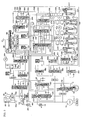
- Fig. 3 is a diagram showing an embodiment of a hydraulic control device for an automatic transmission for a vehicle according to the present invention; and
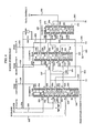
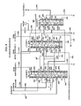
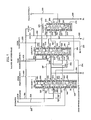
- Figs. 4 through 9 are diagrams showing the essential portion of the hydraulic control device shown in Fig. 3 in the conditions operating at respective speed stages.
- In the following the invention will be described in detail with respect to some preferred embodiments thereof with reference to the accompanying drawings.
- Referring to Fig. 1, the speed stage shifting mechanism herein shown comprises a first planetary gear mechanism having a
first sun gear 10, afirst ring gear 12 coaxial with saidfirst sun gear 10, a firstplanetary pinion 14 meshing with saidfirst sun gear 10 and saidfirst ring gear 12, and afirst carrier 16 rotatably supporting said firstplanetary pinion 14, and a second planetary gear mechanism having a second sun gear 20, asecond ring gear 22 coaxial with said second sun gear 20, a second planetary pinion 24 meshing with said second sun gear 20 and saidsecond ring gear 22, and asecond carrier 26 rotatably supporting said second planetary pinion 24. Thefirst ring gear 12 is connected with thesecond carrier 26 by a connectingmember 30. Thefirst carrier 16 is connected with thesecond ring gear 22 by a connectingmember 32. - A first one way clutch 34 and a second one
way clutch 36 are provided in series between ahousing 50 and thefirst carrier 16 which is also connected with thesecond ring gear 22 by the connectingmember 32. The first oneway clutch 34 is closer to thefirst carrier 16 and the second oneway clutch 36 is closer to thehousing 50. In more detail, the first oneway clutch 34 has aninner race 34a connected with thefirst carrier 16 and an outer race 34b connected via a connectingmember 31 with an inner race 36a of the second one way clutch which also has anouter race 36b connected with thehousing 50. - The first one
way clutch 34 is engaged when the outer race 34b would rotate relative to theinner race 34a in in a first rotational direction and slips when theinner race 34a rotates relative to the outer race 34b in a second direction opposite to said first direction. Similarly, the second oneway clutch 36 is engaged when the inner race 36a would rotate relative to theouter race 36b in said first direction and slips when the inner race 36a rotates relative to the outer race 36a in said second direction. - The
second carrier 26 is connected with anannular gear member 54 which operates as an output rotational member of this speed stage shifting mechanism. - A
first clutch 38 is provided between the second sun gear 20 and aninput shaft 52 for selectively connecting these two members with one another. Asecond clutch 40 is provided between thefirst carrier 16 and theinput shaft 52 for selectively connecting these two members with one another. A third clutch 42 is provided between thefirst sun gear 10 and theinput shaft 52 for selectively connecting these two members with one another. A fourth clutch 44 is provided between thefirst sun gear 10 and the connectingmember 31 for selectively connecting thesun gear 10 with the outer race 34b of the one way clutch 34 and theinner race 36b of the one way clutch 36. - A first brake 46 is provided between the connecting
member 31 and thehousing 50 for selectively fixing the connectingmember 31 relative to thehousing 50. A second brake 48 is provided between the combination of thesecond ring gear 22 and thefirst carrier 16 and thehousing 50 for selectively fixing thesecond ring gear 22 and thefirst carrier 16 with respect to thehousing 50. - The manner of providing a first speed stage, a second speed stage, a third speed stage (direct connection stage), a fourth speed stage (overdrive stage) and a reverse stage is shown in Table 1 and Fig. 2. In Table 1 and Fig. 2 a circle (○) indicates that the corresponding clutch, brake or one way clutch is engaged in engine drive state, and in Table 1 a circle in parentheses ((○)) indicates that the corresponding clutch or brake is engaged to provide the corresponding speed stage with the effect of engine braking.
- When the ratio of the number of gear teeth of the
first ring gear 12 to that of thefirst sun gear 10 is r₁, and the ratio of the number of gear teeth of thesecond ring gear 22 to that of the second sun gear 20 is r₂, speed change gear ratios at the respective speed stages are as shown in Table 2. - The
first clutch 38, thesecond clutch 40, the third clutch 42, the fourth clutch 44, the first brake 46 and the second brake 48 are all of a hydraulically operating type having, as shown in Fig. 3,hydraulic pressure chambers - The
input shaft 52 of the above-mentioned planetary gear type speed change device is drivingly connected with a motor such as an internal combustion engine not shown in the figure via afluid torque converter 60 such as shown in Fig. 3. - The
fluid torque converter 60 is of a three elements two phases type comprising apump impeller 62 drivingly connected with an output member of the motor, aturbine rotor 64 drivingly connected with theinput shaft 52 of the planetary gear type speed stage shifting mechanism, and astator 66 rotatable only in one direction. Thefluid torque converter 60 further comprises a lock-up clutch 68 which is engaged to connect thepump impeller 62 directly with theturbine rotor 64 when a hydraulic pressure is supplied to itsport 60a and is disengaged when a hydraulic pressure is supplied to its port 60b. The supply of hydraulic pressure to theports 60a and 60b is carried out by the hydraulic control device shown in Fig. 3. - The outline of the oil hydraulic control device shown in Fig. 3 will now be described with further reference to Figs. 4-9 with respect to the operations in the D range and the S range and the S range.
- The oil hydraulic control device comprises a
pump 70 which takes in an operating hydraulic fluid such as an oil from a reservoir not shown in the figure and supplies the hydraulic fluid to aprimary regulator valve 80 generally called a line pressure control valve and also to athrottle valve 120. The maximum value of the hydraulic pressure supplied by thepump 70 to theprimary regulator valve 80 is restricted by apressure relief valve 72. - The
throttle valve 120 provides in a passage 138 a hydraulic pressure which varies in accordance with the load on the engine and is generally called a throttle pressure. - The
primary regulator valve 80 is supplied with the throttle pressure and a reverse boost pressure and provides in a passage 98 the line pressure which generally increases along with increase of the throttle opening and a hydraulic pressure for asecondary regulator valve 100 generally called a converter pressure control valve. - The
secondary regulator valve 100 is supplied with the throttle pressure and provides a converter pressure (lubricating oil pressure) in apassage 118. The line pressure in the passage 98 is supplied to aport 194 of amanual valve 190. Themanual valve 190 has aspool 192 adapted to be operated by a hand of a driver and selectively provides the line pressure supplied to theport 194 at aD port 196 in the so-called D range, also at anS port 198 in the so-called S range, further at anL port 200 in the so-called L range, and at anR port 202 in the so-called R range. - The line pressure supplied to the
D port 196 is conducted through apassage 204 to a D port 214 of a 1-2shift valve 210, aD port 246 of a 2-3shift valve 240, and aD port 274 of a 3-4shift valve 270. The line pressure supplied to theS port 198 is conducted through apassage 206 to anS port 248 of the 2-3shift valve 240. The line pressure supplied to theL port 200 is conducted through apassage 208 to anL port 250 of the 2-3shift valve 240. The line pressure supplied to theR port 202 is conducted through apassage 203 to a reverse inhibit valve 360. - As shown in more detail in Fig. 4 the 2-3
shift valve 240 comprises aspool element 242 and aplug element 244, and in addition to the above-mentioned ports further comprisesdrain ports clutch port 254,brake ports safe port 260. When a hydraulic pressure is supplied to acontrol port 261, theplug element 244 and thespool element 242 are shifted downward in the figure to a "1,2" shift position as shown in the right half portion thereof by overcoming the spring force of acompression coil spring 262 so as to connect theclutch port 254 with thedrain port 252, thebrake port 256 with theS port 248, thebrake port 258 with theL port 250, and the failsafe port 260 with theD port 246, respectively. In contrast, when no hydraulic pressure is supplied to thecontrol port 261, theplug element 244 and thespool element 242 are shifted upward in the figure to a "3,4" shift position as shown in the left half portion thereof by the spring force of the compressingcoil spring 262 so as to connect theclutch port 254 with theD port 246, and thebrake ports safe port 260 with thedrain ports control port 261 is controlled by afirst solenoid valve 400. - The
clutch port 254 is connected through apassage 263 with thehydraulic pressure chamber 40a of the second clutch 40 and anaccumulator chamber 472 of anaccumulator 470 for the clutch C₂. Theclutch port 254 is also connected through apassage 264 with ahold port 220 of the 1-2shift valve 210, and also through apassage 265 with a failsafe port 222 of the 1-2shift valve 210. The failsafe port 222 also has a concept of drain port because it is connectable to drain throughports brake port 256 is connected through apassage 266 with theS port 216 of the 1-2shift valve 210. Thebrake port 258 is connected through apassage 267 with theL port 218 of the 1-2shift valve 210. The failsafe port 260 is connected through apassage 268 with ahold port 278 of the 3-4shift valve 270 and also connected through apassage 269 with adrain port 280 of the 3-4shift valve 270. - As also shown in Fig. 4, the 1-2
shift valve 210 comprises aspool element 212, and in addition to the above-mentioned ports further comprises aclutch port 224,brake ports R port 230, aport 232 and aclutch port 234. When a hydraulic pressure is supplied to a control port 238 thespool element 212 is shifted downward in the figure as shown in the left half portion thereof to a "1" shift position by overcoming the spring force of acompression coil spring 236 so as to connect theclutch port 224 with the failsafe port 222, thebrake port 226 with theR port 230, and thebrake port 228 with theL port 218, while isolating theport 232 from theclutch port 234. In contrast, when no hydraulic pressure is supplied to the control port 238, thespool element 212 is shifted upward in the figure as shown in the right half portion thereof to a "2,3,4" shift position by the spring force of thecompression coil spring 236 so as to connect theclutch port 224 with the D port 214, thebrake port 226 with theS port 216, thebrake port 228 with theR port 230, and theport 232 with theclutch port 234. - The supply of the hydraulic pressure to the control port 238 is controlled by a
second solenoid valve 410. The control port 238 is connected through apassage 239 with acontrol port 288 of the 3-4shift valve 270. - The
clutch port 224 is connected through apassage 225 with thehydraulic pressure chamber 44a of the fourth clutch 44 and anaccumulator chamber 492 of anaccumulator 490 for the clutch C₄. Thebrake port 226 is connected through apassage 227 with anS port 276 of the 3-4shift valve 270. Thebrake port 228 is connected through apassage 229 with an accumulator chamber 532 of an accumulator 530 for the brake B₂, and is further connected through apassage 231 with the inside hydraulic pressure chamber 48a of the second brake 48. Theport 232 is connected through apassage 233 with a port of aC₁ control valve 300. Theclutch port 234 is connected through apassage 235 with thehydraulic chamber 38a of thefirst clutch 38. - Also referring to Fig. 4, the 3-4
shift valve 270 comprises aspool element 272, and in addition to the above-mentioned ports further comprises aclutch port 282 and abrake port 284. When no hydraulic pressure is supplied to thehold port 278 while a hydraulic pressure is supplied to thecontrol port 288, thespool element 272 is shifted downward in the figure to a "4" shift position as shown in the right half portion thereof by overcoming the spring force of acompression coil spring 286 so as to connect theclutch port 282 with thedrain port 280, and thebrake port 284 with theD port 274. In contrast, when a hydraulic pressure is supplied to thehold port 278, or when no control pressure is supplied to thecontrol port 288, thespool element 272 is shifted upward in the figure to a "1,2,3" shift position as shown in the left half portion thereof by the oil pressure supplied to theport 278 and/or the spring force of thecompression coil spring 286 so as to connect theclutch port 282 with theD port 274, and thebrake port 284 with theS port 276. - The
clutch port 282 is connected through apassage 290 with theC₁ control valve 300. Thebrake port 284 is connected through apassage 292 with the oilhydraulic pressure chamber 46a of the first brake 46 and anaccumulator chamber 512 of an accumulator 510 for the brake B₁. - The
first solenoid valve 400 and thesecond solenoid valve 410 are normally open type valves which open their ports when not energized and close their ports when energized. The manner of energization of these solenoid valves is shown in Fig. 2 in relation with the speed stages to be set up. In Fig. 2 a circle (○) indicates energization of the corresponding solenoid valve. - The
first solenoid valve 400 is connected through apassage 408 with thecontrol port 261 of the 2-3shift valve 240 and is also connected through a passage 406 with a port of theC1 control valve 300. - The
second solenoid valve 410 is connected through apassage 418 with the control port 238 of the 1-2shift valve 210, and is also connected through apassage 239 with thecontrol port 288 of the 3-4shift valve 270. - Therefore, when the
solenoid valve 400 is energized thecontrol port 261 of the 2-3shift valve 240 is supplied with a hydraulic pressure, and when thesolenoid valve 410 is energized the control port 238 of the 1-2shift valve 210 and also thecontrol port 288 of the 3-4shift valve 270 are supplied with a hydraulic pressure. - The
C₁ control valve 300 controls switching over of the first clutch 38 by switching over the connection of thepassage 290 withpassages - The
passage 328 is connected through apassage 329, anaccumulator chamber 452 of anaccumulator 450 for the clutch C₁, apassage 468 and a oneway valve 469 with thehydraulic pressure chamber 38a of thefirst clutch 38. Thepassage 326 is connected with a port of a 4-3 control valve 330. - The 4-3 control valve 330 controls the timing of the engagement of the first clutch 38 in speed stage shifting between the third speed stage and the fourth speed stage by connecting the
passage 326 with either apassage 352 or apassage 356 incorporating anorifice 350 or 354 having each particular throttling ratio so as to switch over the rate of supply of hydraulic pressure to thehydraulic pressure chamber 38a. Thepassages passage 329 which is connected through theaccumulator chamber 452, thepassage 468 and the oneway valve 469 with thehydraulic pressure chamber 38a of thefirst clutch 38. - The reverse inhibit valve 360 is supplied with the line pressure from the
R port 202 of themanual valve 190 through apassage 203, and is switched over according to opening or closing of thethird solenoid valve 420 so as to be at an inhibit position where a spool 362 is shifted up as shown in a left half portion thereof when the vehicle is running forward at a speed greater than a predetermined value and to be in a non inhibit position where the spool element 362 is shifted down as shown in the right half portion thereof during other operating conditions while allowing the line pressure from thepassage 203 to flow to thepassage 398 toward thehydraulic pressure chamber 42a of the third clutch 42, to thepassages R port 230 of the 1-2shift valve 210, and also to thepassage 396, aB₂ sequence valve 610 and a passage 392 toward the outsidehydraulic pressure chamber 48b of the second brake 48. - The
B₂ sequence valve 610 operates in response to the hydraulic pressure in the inside hydraulic pressure chamber 48a of the second brake 48 so as to connect thepassage 396 with the passage 392 so that the outsidehydraulic pressure chamber 48b is supplied with the hydraulic pressure when the oil pressure in the inside hydraulic pressure chamber 48a is greater than a predetermined value. -
Accumulators pressure chambers accumulator control valve 560. The secondaccumulator control valve 560 is supplied with a duty hydraulic pressure controlled by aduty solenoid valve 590 and the hydraulic pressure from the firstaccumulator control valve 550 to change its output control pressure. Theduty solenoid valve 590 is supplied with a pulse signal having a determinate duty ratio and cyclically opens and closes according to the duty ratio so as to control a modulate hydraulic pressure from aduty control valve 580 according to the duty ratio. The duty hydraulic pressure controlled by theduty solenoid valve 590 for the secondaccumulator control valve 560 is rectified of its pulses by aduty pressure accumulator 600. The firstaccumulator control valve 550 is supplied with the throttle pressure from thethrottle valve 138 so as to control the oil pressure supplied to the secondaccumulator control valve 560 and the 4-3 control valve 330 in accordance with the throttle pressure. - The supply of the converter pressure to the
ports 60a and 60b of thefluid torque converter 60 is controlled by a lock up relay valve 140. The lock up relay valve 140 is switched over according to a selective supply of an oil pressure from a lock upsignal valve 160. The lock up relay valve 140 supplies hydraulic fluid, i.e., oil, toward anoil cooler 170. The hydraulic pressure in the passage including theoil cooler 170 is limited by a cooler by-pass valve 172 and arelief valve 174. The lock upsignal valve 160 is supplied with an oil pressure from theclutch port 224 of the 1-2shift valve 210 and is switched over in accordance with on and off of thethird solenoid valve 420 so as to supply the hydraulic pressure supplied from theclutch port 224 to the lock up relay valve 140 and to engage the lock up clutch 68 when thethird solenoid valve 420 is energized. Thethird solenoid valve 420 is selectively energized as shown in Fig. 2 for inhibiting engagement of the lock up clutch 68 in the reverse stage where the manual shift valve is shifted to the R range and when the manual shift valve is sifted to the D range. - The operation of the hydraulic control device according to the present invention will now be described principally with respect to the speed stage shifting operation under the D range and the S range with reference to Figs. 4-9. In Figs. 4-9 the bold lines indicate that a hydraulic pressure is supplied in those lines in the respective speed stages.
- First referring to Fig. 4, the operation in the first speed stage under the D range will be described. When the manual shift valve is set to the D range, the
manual shift valve 190 provides the line pressure only at theD port 196. - In the first speed stage the
first solenoid valve 400 and thesecond solenoid valve 410 are both energized, and therefore thecontrol port 261 of the 2-3shift valve 240, the control port 238 of the 1-2shift valve 210 and thecontrol port 288 of the 3-4shift valve 270 are supplied with the hydraulic pressure. Therefore, theplug element 244 and thespool element 242 of the 2-3shift valve 240 are shifted to the "1,2" shift position shown in the right half portion thereof, and thespool element 212 of the 1-2shift valve 210 is shifted to the "1" shift position shown in the left half portion thereof. Therefore, the line pressure from theD port 196 of themanual shift valve 190 is supplied through thepassage 204, theD port 246 of the 2-3shift valve 240, the failsafe port 260, and thepassage 268 to thehold port 278 of the 3-4shift valve 270. The 3-4shift valve 270 is supplied with the hydraulic pressure at thecontrol port 288. However, since thehold port 278 is also supplied with the hydraulic pressure, thespool element 272 is shifted to the "1,2,3" shift position shown in the left half portion thereof by the spring force of thecompression coil spring 286. Therefore, theD port 274 is connected with theclutch port 282, and the line pressure from theD port 196 of themanual shift valve 190 is supplied thepassage 290, theC₁ control valve 300, through thepassages accumulator chamber 452 of theaccumulator 450 for the clutch C1, and the oneway valve 469 to thehydraulic pressure chamber 38a of the first clutch C₁ which is then engaged. Thus the first speed stage of the D range is set up. - Next, referring to Fig. 5, the second speed stage under the D range will be described. In this speed stage the
first solenoid valve 400 is only energized, so that thecontrol port 261 of the 2-3shift valve 240 only is still supplied with the oil pressure. Therefore, theplug element 244 and thespool element 242 of the 2-3shift valve 240 remain in the "3,4" shift position, whereas thespool element 212 of the 1-2shift valve 210 is shifted to the "2,3,4" shift position shown in the right half portion thereof by the spring force of thecompression coil spring 236. In the 3-4shift valve 270 the hydraulic pressure in thecontrol port 288 disappears and thespool element 272 still remains at the "1,2,3" shift portion shown in the left half portion thereof by the hydraulic pressure supplied to thehold port 278 and the spring force of thecompression coil spring 286. By the shifting over of the 1-2shift valve 210 the D port 214 is now connected with theclutch port 224 so that the line pressure from theD port 196 of themanual shift valve 190 is supplied to thepassage 225 to thehydraulic pressure chamber 44a of the fourth clutch 44 which is then engaged. Thus the first clutch 38 and the fourth clutch 44 are engaged, thereby setting up the second speed stage of the D range. - Next, referring to Fig. 6, the third speed stage under the D range will be described. In this speed stage the
first solenoid valve 400 and thesecond solenoid valve 410 are both not energized, so that the control port 238 of the 1-2shift valve 210 and thecontrol port 261 of the 2-3shift valve 240 are both not supplied with hydraulic pressure. Therefore, theplug element 244 and thespool element 242 of the 2-3shift valve 240 are lifted to the "3,4" shift position as shown in the left half portion in the figure by the spring force of thecompression coil spring 262, whereby theD port 246 of the 2-3shift valve 240 is isolated from the failsafe port 260 thereof and is connected with theclutch port 254. Thus the line pressure from theD port 196 of themanual shift valve 190 is conducted through thepassage 263 to thehydraulic pressure chamber 40a of the second clutch 40 which is then engaged. In the 3-4shift valve 270, although thehold port 278 is no longer supplied with the hydraulic pressure, thespool element 272 still remains in the lifted "1,2,3" shift position by the spring force of thecompression coil spring 286. In the 1-2shift valve 210, thespool element 212 remains in the lifted "2,3,4" shift position as in the second speed stage. Therefore, in addition to the first clutch 38 and the fourth clutch 44 the second clutch 40 is now engaged, thereby setting up the third speed stage of the D range. - Next, referring to Fig. 7, the fourth speed stage under the D range will be described. In this speed stage the
second solenoid valve 410 only is energized. Therefore, the control port 238 of the 1-2shift valve 210 and thecontrol port 288 of the 3-4shift valve 270 are supplied with the hydraulic pressure. In the 1-2shift valve 210 thehold port 220 is supplied with the hydraulic pressure from theclutch port 254 of the 2-3shift valve 240 through thepassage 264. Therefore, in spite of the supply of the hydraulic pressure to the control port 238 thespool element 212 remains in the lifted "2,3,4" shift position shown in the right half portion thereof by the spring force of thecompression coil spring 236. However, in the 3-4shift valve 270, since thehold port 278 is connected through thepassage 268 and the failsafe port 260 of the 2-3shift valve 240 to thedrain port 253, thespool element 272 is shifted downward in the "4" shift position by the oil pressure supplied to thecontrol port 288 by overcoming the spring force of thecompression coil spring 286. Therefore, theD port 274 is connected with thebrake port 284 instead of theclutch port 282 which is now connected to the drain port through theport 280. Thus thehydraulic pressure chamber 38a of the first clutch 38 is now exhausted of the oil pressure, and the first clutch 38 is disengaged. Instead the line pressure is supplied to thehydraulic pressure chamber 46a of the first brake 46 which is now engaged. Therefore, the second clutch 40, the fourth clutch 44 and the first brake 46 are engaged, thereby setting up the overdrive fourth speed stage of the D range. - When the manual shift valve is set to the D range, the
manual shift valve 190 provides the line pressure only at theD port 196. At this time the 2-3shift valve 240 is supplied with the line pressure from themanual shift valve 190 only at theD port 246 thereof. However, when themanual shift valve 190 is shifted to the L range, themanual shift valve 190 provides at itsS port 198 and itsL port 200 in addition to theD port 196, and in accordance with this in the 2-3shift valve 240 the line pressure is supplied to itsS port 248 and itsL port 250 in addition to itsD port 246. - Next, referring to Fig. 8 the first speed stage under the S range will be described. In this state, as in the first speed stage under the D range, the
first solenoid valve 400 and thesecond solenoid valve 410 are both energized, and therefore thecontrol port 261 of the 2-3shift valve 240, the control port 238 of the 1-2shift valve 210, and thecontrol port 288 of the 3-4shift valve 270 are supplied with the hydraulic pressure. Therefore, the 2-3shift valve 240, the 1-2shift valve 210 and the 3-4shift valve 270 are switched over in the respective positions which are the same as in the first speed stage under the D range. Therefore, thehydraulic pressure chamber 38a of the first clutch 38 is supplied with the hydraulic pressure to engage the clutch 38. Since at this time theS port 248 of the 2-3shift valve 240 is supplied with the line pressure from themanual shift valve 190, this line pressure is transmitted through abrake port 256 and thepassage 266 to theS port 216 of the 1-2shift valve 210. However, since thevalve element 212 in the 1-2shift valve 210 is shifted to the first shift position as shown in the left half portion thereof in the figure, the line pressure is not transmitted further. - Next, with reference to Fig. 9 the second speed stage under the S range will be described. In this state the
first solenoid valve 400 only is energized as in the second speed stage under the L range, and therefore thecontrol port 261 of the 2-3shift valve 240 is supplied with the hydraulic pressure. Therefore, the 2-3shift valve 240, the 1-2shift valve 210 and the 3-4shift valve 270 are shifted to the respective shift positions which are the same as in the second speed stage under the D range. Therefore, thehydraulic pressure chamber 38a of the first clutch 38 and thehydraulic pressure chamber 44a of the fourth clutch 44 are supplied with the hydraulic pressure, and therefore the first clutch 38 and the fourth clutch 44 are engaged. In this state, since theS port 248 of the 2-3shift valve 240 is supplied with the line pressure from themanual shift valve 190, this hydraulic pressure is transmitted through thebrake port 256 and thepassage 266 to theS port 216 of the 1-2shift valve 210, and further through thebrake port 226 and thepassage 227 to theS port 276 of the 3-4shift valve 270 which serves as an exhaust port for the first brake 46 in speed stages other than the present speed stage. Further the hydraulic pressure is transmitted through thebrake port 284 and thepassage 292 to thehydraulic pressure chamber 46a of the first brake 46, so as to engage the first brake 46. Thus the second speed stage having the engine braking effect is set up. In order to disengage the first brake 46 in the first, the second and the third speed stage under the D range and in the first speed stage under the S range, thehydraulic pressure chamber 46a is exhausted through theS port 276 of the 3-4shift valve 270. That is, in the first speed stage under the D range theS port 276 is connected through thepassage 227, thebrake port 226 and theR port 230 of the 1-2shift valve 210 and thepassage 394 to the reverse inhibition valve 360 so as to exhaust thehydraulic pressure chamber 46a. Further in the second speed stage under the D range, theS port 276 is connected through thepassage 227, thebrake port 226 and theS port 216 of the 1-2shift valve 210 and thepassage 266 to thebrake port 256 of the 2-3shift valve 240, and then is further connected through theS port 248 and thepassage 206 to themanual shift valve 190 so as to exhaust thehydraulic pressure chamber 46a. In the third speed stage under the D range, theS port 276 is connected through thepassage 227, thebrake port 226 and theS port 216 of the 1-2shift valve 210, thepassage 266 and thebrake port 256 of the 2-3shift valve 240 to thedrain port 251 so as to exhaust thehydraulic pressure chamber 46a. - In the first speed stage under the S range, the
S port 276 is, in the same manner as in the first speed stage under the D range, connected through thepassage 227, thebrake port 226 and theR port 230 of the 1-2shift valve 290 and thepassage 394 to the reverse inhibition valve 360, so as to exhaust thehydraulic pressure chamber 46a. - Even under the S range, if the vehicle speed is so high as to cause an overrun of the engine, the third speed stage is set up. In this state the
hydraulic pressure chamber 46a of the first brake 46 is exhausted through theS port 276 of the 3-4shift valve 270, thepassage 227, thebrake port 226 and theS port 216 of the 1-2shift valve 210, thepassage 266, thebrake port 256 and thedrain port 251 of the 2-3shift valve 240. - Although the invention has been described in detail with respect to a preferred embodiment thereof, it will be apparent to those skilled in the art that various modifications are possible with respect to the shown embodiment within the scope of the present invention.
Table 1 C₁ C₂ C₃ C₄ B₁ B₂ F₁ F₂ 38 40 42 44 46 48 34 36 1st Speed Stage ○ (○) ○ ○ 2nd Speed Stage ○ ○ (○) ○ 3rd Speed Stage ○ ○ ○ ○ 4th Speed Stage ○ ○ ○ Reverse Stage ○ ○ Table 2 Speed Change Gear Ratio 1st Speed Stage (1+r₂)/r₂ 2nd Speed Stage {(1+r₂)/r₂}-{1/r₂(1+r₁)} 3rd Speed Stage 1 4th Speed Stage 1/(1+r₁) Reverse Stage -1/r₁
Claims (3)
a first shift valve for controlling supply and exhaust of a hydraulic pressure to and from said first friction engaging means for switching over speed stages between said certain speed stage and said speed stage on a higher side of said certain speed stage and for controlling supply and exhaust of a hydraulic pressure to and from said second friction engaging means, said first shift valve having a drain port for exhausting a hydraulic pressure from said second friction engaging means, and
a second shift valve adapted to be shifted between shift positions for switching over speed stages between said certain speed stage and said speed stage on a lower side of said certain speed stage and adapted to be supplied with a hydraulic pressure from a manual shift valve under said another manual shift range, said second shift valve transmitting said hydraulic pressure from said manual shift valve to said drain port of said first shift valve for said second friction engaging means when said second shift valve is shifted to a position thereof for setting up said speed stage on the lower side of said certain speed stage.
Applications Claiming Priority (4)
| Application Number | Priority Date | Filing Date | Title |
|---|---|---|---|
| JP63192965A JP2829976B2 (en) | 1988-08-02 | 1988-08-02 | Hydraulic control device for automatic transmission for vehicles |
| JP192965/88 | 1988-08-02 | ||
| JP63278346A JP2913649B2 (en) | 1988-11-02 | 1988-11-02 | Hydraulic control device for automatic transmission for vehicles |
| JP278346/88 | 1988-11-02 |
Publications (3)
| Publication Number | Publication Date |
|---|---|
| EP0354007A2 true EP0354007A2 (en) | 1990-02-07 |
| EP0354007A3 EP0354007A3 (en) | 1992-02-26 |
| EP0354007B1 EP0354007B1 (en) | 1994-11-02 |
Family
ID=26507620
Family Applications (1)
| Application Number | Title | Priority Date | Filing Date |
|---|---|---|---|
| EP89307831A Expired - Lifetime EP0354007B1 (en) | 1988-08-02 | 1989-08-01 | Hydraulic control device for automatic transmission for vehicle having friction engaging means operative in two jumping apart speed stages |
Country Status (3)
| Country | Link |
|---|---|
| US (1) | US4982624A (en) |
| EP (1) | EP0354007B1 (en) |
| DE (1) | DE68919150T2 (en) |
Cited By (1)
| Publication number | Priority date | Publication date | Assignee | Title |
|---|---|---|---|---|
| DE19549005A1 (en) * | 1994-12-28 | 1996-07-11 | Hyundai Motor Co Ltd | Hydraulic control system for five speed automatic transmission for motor vehicle |
Families Citing this family (5)
| Publication number | Priority date | Publication date | Assignee | Title |
|---|---|---|---|---|
| JPH03125063A (en) * | 1989-10-09 | 1991-05-28 | Toyota Motor Corp | Hydraulic controller for automatic transmission for vehicle |
| US5235877A (en) * | 1991-02-28 | 1993-08-17 | Toyota Jidosha Kabushiki Kaisha | Shift control apparatus for automatic transmission |
| US5725451A (en) * | 1994-06-02 | 1998-03-10 | Aisin Aw Co., Ltd. | Control system for automatic transmission |
| US5674154A (en) * | 1994-12-02 | 1997-10-07 | Aisin Aw Co., Ltd. | Hydraulic control system for automatic transmission |
| JP3541087B2 (en) * | 1995-06-16 | 2004-07-07 | トヨタ自動車株式会社 | Control device for automatic transmission |
Citations (4)
| Publication number | Priority date | Publication date | Assignee | Title |
|---|---|---|---|---|
| US4134313A (en) * | 1976-05-11 | 1979-01-16 | Aisin Seiki Kabushiki Kaisha | Automatic transmission for automobiles |
| US4579020A (en) * | 1983-07-29 | 1986-04-01 | Nissan Motor Co., Ltd. | Hydraulic control system for automatic transmission |
| EP0179683A2 (en) * | 1984-09-18 | 1986-04-30 | Regie Nationale Des Usines Renault | Control device for an automatic transmission with four ratios |
| EP0302723A2 (en) * | 1987-08-05 | 1989-02-08 | Toyota Jidosha Kabushiki Kaisha | Planetary gear type speed change device having one-way clutch operable in two functions |
Family Cites Families (5)
| Publication number | Priority date | Publication date | Assignee | Title |
|---|---|---|---|---|
| US3896685A (en) * | 1973-09-12 | 1975-07-29 | Gen Motors Corp | Transmission control for a transmission having one drive establishing device for two independent drive functions |
| JPS5174169A (en) * | 1974-12-23 | 1976-06-26 | Toyota Motor Co Ltd | Jidohensokukino yuatsuseigyosochi |
| US4379134A (en) * | 1981-02-13 | 1983-04-05 | Union Carbide Corporation | Process of preparing high purity alumina bodies |
| US4719822A (en) * | 1984-04-04 | 1988-01-19 | Toyota Jidosha Kabushiki Kaisha | Hydraulic pressure control apparatus for use in an automotive transmission |
| JPS6241466A (en) * | 1985-08-15 | 1987-02-23 | Nissan Motor Co Ltd | Forward pressure control and torque converter control device for automatic transmission |
-
1989
- 1989-08-01 DE DE68919150T patent/DE68919150T2/en not_active Expired - Fee Related
- 1989-08-01 EP EP89307831A patent/EP0354007B1/en not_active Expired - Lifetime
- 1989-08-02 US US07/388,612 patent/US4982624A/en not_active Expired - Lifetime
Patent Citations (4)
| Publication number | Priority date | Publication date | Assignee | Title |
|---|---|---|---|---|
| US4134313A (en) * | 1976-05-11 | 1979-01-16 | Aisin Seiki Kabushiki Kaisha | Automatic transmission for automobiles |
| US4579020A (en) * | 1983-07-29 | 1986-04-01 | Nissan Motor Co., Ltd. | Hydraulic control system for automatic transmission |
| EP0179683A2 (en) * | 1984-09-18 | 1986-04-30 | Regie Nationale Des Usines Renault | Control device for an automatic transmission with four ratios |
| EP0302723A2 (en) * | 1987-08-05 | 1989-02-08 | Toyota Jidosha Kabushiki Kaisha | Planetary gear type speed change device having one-way clutch operable in two functions |
Cited By (1)
| Publication number | Priority date | Publication date | Assignee | Title |
|---|---|---|---|---|
| DE19549005A1 (en) * | 1994-12-28 | 1996-07-11 | Hyundai Motor Co Ltd | Hydraulic control system for five speed automatic transmission for motor vehicle |
Also Published As
| Publication number | Publication date |
|---|---|
| EP0354007B1 (en) | 1994-11-02 |
| EP0354007A3 (en) | 1992-02-26 |
| US4982624A (en) | 1991-01-08 |
| DE68919150T2 (en) | 1995-03-30 |
| DE68919150D1 (en) | 1994-12-08 |
Similar Documents
| Publication | Publication Date | Title |
|---|---|---|
| JP2952553B2 (en) | Control device for hydraulically operated transmission | |
| EP0354006B1 (en) | Hydraulic control device for automatic transmission for vehicle having two parallel input clutches | |
| US5115696A (en) | Hydraulic pressure control device with parallel pressure supply passages for certain one friction engaging means | |
| EP0354004A2 (en) | Hydraulic control device for automatic transmission for vehicle adapted to engage clutch at different speed according to engine output power | |
| EP0354007B1 (en) | Hydraulic control device for automatic transmission for vehicle having friction engaging means operative in two jumping apart speed stages | |
| EP0356036B1 (en) | Hydraulic control device for automatic transmission for vehicle having clutch operable in two speed stages and two parallel hydraulic pressure supply passages therefor | |
| EP0354005B1 (en) | Hydraulic control device for automatic transmission for vehicle with high accuracy reverse inhibition system | |
| US5029493A (en) | Hydraulic control device in automatic transmission in vehicle equipped with electronic throttle opening control device | |
| EP0354003A2 (en) | Hydraulic control device for automatic transmission for vehicle having clutch disengage control means independent of clutch engage control means | |
| US4920829A (en) | Hydraulic pressure control device for automatic transmission for vehicle including reverse stage and lock-up clutch control systems | |
| US5984818A (en) | Hydraulic control system for automatic transmissions | |
| EP0329307B1 (en) | Hydraulic pressure control device for automatic transmission for vehicle including reverse stage and lock-up clutch control systems | |
| US4779492A (en) | Twin type hydraulic pressure control device with individual line pressure regulation valves for two stage automatic transmission | |
| JP2658228B2 (en) | Hydraulic control device for automatic transmission for vehicles | |
| JP3057680B2 (en) | Shift valve for hydraulic control device of vehicle automatic transmission | |
| JP2803438B2 (en) | One-way clutch friction prevention device for automatic transmission | |
| JP2829976B2 (en) | Hydraulic control device for automatic transmission for vehicles | |
| JP2913649B2 (en) | Hydraulic control device for automatic transmission for vehicles | |
| JP2926714B2 (en) | Hydraulic control device for automatic transmission for vehicles | |
| JP2800340B2 (en) | Shift control method for automatic transmission for vehicle | |
| JPH02134459A (en) | Hydraulic control device for lockup clutch control of automatic transmission for vehicle | |
| JPH09210196A (en) | Hydraulic controller for automatic transmission | |
| JPH02125166A (en) | Hydraulic control device of automatic transmission for vehicle | |
| JPH0276967A (en) | Oil pressure control device for automatic speed change gear for vehicle | |
| JPH0674848B2 (en) | Automatic transmission with PTO Lockup controller for tower mounted vehicle |
Legal Events
| Date | Code | Title | Description |
|---|---|---|---|
| PUAI | Public reference made under article 153(3) epc to a published international application that has entered the european phase |
Free format text: ORIGINAL CODE: 0009012 |
|
| AK | Designated contracting states |
Kind code of ref document: A2 Designated state(s): DE FR GB |
|
| PUAL | Search report despatched |
Free format text: ORIGINAL CODE: 0009013 |
|
| AK | Designated contracting states |
Kind code of ref document: A3 Designated state(s): DE FR GB |
|
| 17P | Request for examination filed |
Effective date: 19920221 |
|
| 17Q | First examination report despatched |
Effective date: 19930622 |
|
| GRAA | (expected) grant |
Free format text: ORIGINAL CODE: 0009210 |
|
| AK | Designated contracting states |
Kind code of ref document: B1 Designated state(s): DE FR GB |
|
| REF | Corresponds to: |
Ref document number: 68919150 Country of ref document: DE Date of ref document: 19941208 |
|
| ET | Fr: translation filed | ||
| PLBE | No opposition filed within time limit |
Free format text: ORIGINAL CODE: 0009261 |
|
| STAA | Information on the status of an ep patent application or granted ep patent |
Free format text: STATUS: NO OPPOSITION FILED WITHIN TIME LIMIT |
|
| 26N | No opposition filed | ||
| REG | Reference to a national code |
Ref country code: GB Ref legal event code: 746 Effective date: 19980106 |
|
| REG | Reference to a national code |
Ref country code: FR Ref legal event code: D6 |
|
| REG | Reference to a national code |
Ref country code: GB Ref legal event code: IF02 |
|
| PGFP | Annual fee paid to national office [announced via postgrant information from national office to epo] |
Ref country code: DE Payment date: 20070726 Year of fee payment: 19 |
|
| PGFP | Annual fee paid to national office [announced via postgrant information from national office to epo] |
Ref country code: GB Payment date: 20070801 Year of fee payment: 19 |
|
| PGFP | Annual fee paid to national office [announced via postgrant information from national office to epo] |
Ref country code: FR Payment date: 20070808 Year of fee payment: 19 |
|
| GBPC | Gb: european patent ceased through non-payment of renewal fee |
Effective date: 20080801 |
|
| REG | Reference to a national code |
Ref country code: FR Ref legal event code: ST Effective date: 20090430 |
|
| PG25 | Lapsed in a contracting state [announced via postgrant information from national office to epo] |
Ref country code: FR Free format text: LAPSE BECAUSE OF NON-PAYMENT OF DUE FEES Effective date: 20080901 Ref country code: DE Free format text: LAPSE BECAUSE OF NON-PAYMENT OF DUE FEES Effective date: 20090303 |
|
| PG25 | Lapsed in a contracting state [announced via postgrant information from national office to epo] |
Ref country code: GB Free format text: LAPSE BECAUSE OF NON-PAYMENT OF DUE FEES Effective date: 20080801 |