EP0352807B1 - Athletic shoe having an insert member - Google Patents
Athletic shoe having an insert member Download PDFInfo
- Publication number
- EP0352807B1 EP0352807B1 EP89113980A EP89113980A EP0352807B1 EP 0352807 B1 EP0352807 B1 EP 0352807B1 EP 89113980 A EP89113980 A EP 89113980A EP 89113980 A EP89113980 A EP 89113980A EP 0352807 B1 EP0352807 B1 EP 0352807B1
- Authority
- EP
- European Patent Office
- Prior art keywords
- insert member
- outsole
- athletic shoe
- insert
- midsole
- Prior art date
- Legal status (The legal status is an assumption and is not a legal conclusion. Google has not performed a legal analysis and makes no representation as to the accuracy of the status listed.)
- Expired - Lifetime
Links
Images


Classifications
-
- A—HUMAN NECESSITIES
- A43—FOOTWEAR
- A43B—CHARACTERISTIC FEATURES OF FOOTWEAR; PARTS OF FOOTWEAR
- A43B13/00—Soles; Sole-and-heel integral units
- A43B13/14—Soles; Sole-and-heel integral units characterised by the constructive form
- A43B13/18—Resilient soles
- A43B13/181—Resiliency achieved by the structure of the sole
- A43B13/184—Resiliency achieved by the structure of the sole the structure protruding from the outsole
-
- A—HUMAN NECESSITIES
- A43—FOOTWEAR
- A43B—CHARACTERISTIC FEATURES OF FOOTWEAR; PARTS OF FOOTWEAR
- A43B5/00—Footwear for sporting purposes
Definitions
- This invention relates generally to athletic shoes, and more particularly to an apparatus and method for providing increased durability, stability and rebound in athletic shoes.
- the first broad category utilizes different materials and configurations of the midsole to improve cushioning as well as provide effective foot control.
- materials of different hardnesses may be used to provide cushioning and foot control, or a variety of devices may be encapsulated in a midsole to increase cushioning.
- This type of show has the disadvantage of a short life due to breakdown of the materials used to form the midsole. Since many shoes use only ethyl vinyl acetate EVA or polyurethane (PU) for cushioning, the cells of these foams have a tendency to break down and thus diminish the usefulness of the shoe.
- the second category of device utilizes pneumatic devices within the midsole.
- An example of this is taught in U.S. Patent No. 545,705, issued to McDonald.
- the McDonald device is an elastic air filled cushioning device which is incorporated into the heel of a shoe to provide cushioning.
- a similar device is taught in U.S. Patent No. 1,498,838 to Harrison Jr. which uses a number of tubes which lie within the midsole. These tubes are inflated by a valve to maintain a pressure above ambient.
- the tubes in the Harrison Jr. device are made of a flexible inelastic material.
- the disadvantages of encapsulating gas within the midsole of a shoe are numerous. It is exceedingly difficult and costly to encapsulate gas in a material. It is much easier, for example, to cut a piece of conventional midsole material such as ethyl vinyl acetate (EVA) to a desired specification than to make a container which retains pressurized air or other gas.
- EVA ethyl vinyl acetate
- the problem of diffusion of gas from a container can be somewhat decreased by using large molecule gases as the encapsulated gas. Using such a gas is expensive and as such increases the expense of manufacturing such a shoe.
- the third broad category of devices which are intended to increase the cushioning of a shoe include devices which modify an outsole.
- An outsole is typically made of material such as rubber, polyurethane (PU), thermoplastic rubber (e.g., EVA) and the like. These materials are chosen for outsoles because they are wear resistant. Typically, these materials have fairly good memory characteristics. That is, if the outsole material is deformed either by compression or bending forces, it tends to return to its original shape.
- U.S. Patent No. 4,372,058 to Stubblefield which teaches an outsole in which the periphery of the heel of the outsole maintains the remaining portion of the heel of the outsole in a spaced apart relationship to the ground. This configuration is known as a cantilever outsole.
- the cantilever configuration helps to redirect vertical forces while increasing energy return to a runner.
- an outsole which has a plurality of lugs or levers which extend from the periphery of the bottom of the outsole. These lugs are designed to redirect vertical forces on the outsole so that the forces have at least a horizontal component thereby reducing the stresses on a runner.
- the Stubblefield patent provides a shoe which provides both cushioning and stability.
- the EP-A-160415 discloses a running shoe comprising an upper and a sole with an outsole and two midsoles.
- the upper midsole comprises two interchangeable insert members in its heel area and having a hardness greater than the midsole.
- the two insert members being provided for insertion on the outer side of the heel and being arranged to interlock with each other.
- One object of the present invention is to improve the design of the known shoes by providing even better stability and rebound characteristics and to provide a shoe which utilizes a minimum amount of the heavy outsole material found in conventional outsoles.
- the athletic shoe of the present invention includes the use of a conventional upper and a sole attached to the upper.
- the sole includes an outsole having a central heel portion and a plurality of periphery lugs. These lugs are effective to contact the ground and to maintain the central heel portion in a spaced apart relationship to the ground.
- the athletic shoe of the present invention may also include a midsole and an insert member. This insert member is made of a material which may have a hardness greater than the midsole and positioned to cooperate with the outsole by coacting with the outsole.
- the central heel portion of the outsole defines an opening which may expose the insert member.
- Another aspect of the invention is for the periphery lugs to extend downwardly and outwardly from the central heel portion and for insert extensions to also extend downwardly and outwardly.
- the insert has a substantially planar body portion and has insert extensions which extend downward from the body portion.
- the insert member may be made of a number of materials such as a polymeric material such as Hytrel, Delrin, or Rynite, all products made by E.I. Dupont de Nemours & Co., Inc.
- the insert member may also be made of a combination of these materials, for example, a combination of Rynite and Hytrel.
- the polymeric material may be glass-reinforced and may have a number of openings for reducing the weight of the insert or built up portions for increasing the rigidity and strength of the insert member.
- other high memory, resilient material may be used to practice the invention.
- Yet another aspect of the invention is a method for fabricating a sole.
- This method includes the steps of preloading an insert member and encapsulating the insert member in a midsole material whereby the midsole material retains the insert member in a preloaded condition.
- the insert member may have a body portion and a plurality of extensions members which extend downwardly and outwardly from said body portion.
- the insert extensions may be forced into a mold which retains the insert member in a preloaded position.
- Midsole material may then be blown into the mold and set to retain the insert member in the loaded position. This method allows a midsole to store potential energy.
- the insert member has a hardness which is greater than the hardness of the midsole material.
- the insert in this method may be made of a polymeric material such as a polyester elastomer such as Hytrel.
- the material may be a polyamide such as Zytel or the like.
- One advantage of the invention is that the insert member provides improved energy return and improves the memory characteristics of the sole.
- Yet another advantage of the invention is that it increases the life of a shoe because it will not break down and slows fatigue. If a midsole is used in conjunction with the insert, it can slow fatigue of the midsole material.
- Yet another advantage of the invention is that it provides a sole which has improved load characteristics and strength.
- Yet another advantage of the invention is that it allows the midsole to be tuned during manufacture for optimum energy return for its intended end use.
- Yet another advantage of the invention is that it allows a midsole to recover to a relaxed state between strides of a user.
- a shoe which has improved energy return, memory characteristics and increased durability.
- a shoe designated generally as 20, is made of a number of component parts which include an upper 22 and a sole 24.
- any conventional upper 22 may be used to practice the invention.
- an athletic shoe is shown in Figure 1, and the specification is directed in particular to athletic shoes, it is contemplated that the invention may be used on a number of different categories of shoes or boots, for example, hiking boots, casual shoes and the like.
- the upper 22 is attached to a sole 24 in any conventional manner.
- the sole 24 is made up of an outsole 26 made of a material which is wear resistant and provides traction.
- midsole 28 is disposed generally between outsole 26 and upper 22.
- Midsole 28 may take on a number of forms and modifications as an artisan in the field of shoes will readily recognize.
- midsole 28 may be made from a single material or several different materials, each having different characteristics such as density and rebound characteristics.
- the main purpose of midsole 28 is for cushioning and it may be made of a number of different materials, for example, ethyl vinyl acetate, polyurethane, or a combination thereof.
- midsole 28 may include a heel wedge.
- heel region of the shoe is that portion of the shoe which underlies the heel of a wearer. While heel region 30 of shoe 20 has no precise borders, it generally may be considered as that half of the shoe away from the toe of a wearer. Although the term "heel region” is used throughout this specification, it should be noted that this region may extend into what is traditionally known as the arch area of the shoe and may in fact extend well beyond what might traditionally be characterized as the heel.
- lugs 32-46 In heel region 30 of outsole 26, there are a plurality of lugs 32-46 (Fg. 2) which extend downwardly from a central heel portion 47 (Fig. 3) of the heel region 30. Lugs 32-46 are preferably arranged in a cantilever configuration and thus maintain the central heel portion 47 at a spaced relationship to the ground. This is best seen in Figure 3 which illustrates that the central heel portion 47 is prevented from contacting the ground. Sole 24 is shown in an unloaded condition in this figure. In a preferred embodiment of the invention, lugs 32-46 are designed to flare outwardly to change the direction of forces which are disposed substantially perpendicular to the heel.
- a runner may generate, upon foot strike, forces which are up to three times the runner's body weight. If these extreme forces are not dissipated, a runner may face serious and debilitating injuries.
- forces generated during running or other activities are not precisely perpendicular to the heel.
- heel strike for example, the lateral side of a shoe makes contact with the ground first and the shoe then rotates before toe-off.
- Different sports generate varying forces at various angles to a shoe.
- the above-described cantilever outsole serves to redirect forces irrespective of the precise angle of incidence upon a shoe. This cantilever outsole concept is more fully disclosed in U.S. Patent No. 4,372,058 to Stubblefield, the disclosure of which is expressly incorporated herein by reference.
- Each of the lugs 32-46 on outsole 26 have a land 48 for contacting the ground. These lands 48 are configured to make contact with the ground and preferably have a roughened surface to provide traction. Lands 48 may consist of a flat surface as shown in Figure 2 and 3 or may be a point or small area. Each of the lugs 32-46 may have an angled area 50 which leads from the central heel portion 47 to the lands 48. It is preferred that this angled area 50 is a gradual angle as shown in Figure 3, but it may also be vertical. In the embodiment of the invention shown in Figure 2, wedge-shaped portions 28′ of midsole 28 extend between lugs 32-46. The spacing 52 between adjacent lugs enables lugs 32-46 to act more independently of each other.
- the heel portion of the outsole may form a concavity, without individual lugs.
- individual lugs such as the eight lugs 32-46 shown in Figure 2
- Outsole 26 may include a cut-out 54 in substantially the central heel portion 47 of the outsole. Cut-out 54 is provided primarily to reduce the weight of outsole 26 by eliminating material which is not necessary. Because central heel portion 47 never makes contact with the ground, there is no need for the abrasive resistant material of the outsole to be present in that area. By having a cut-out 54, the overall weight of the shoe is reduced without reducing stability. In addition, the outsole may extend up along the side of the midsole for, e.g. basketball shoes and the like.
- the present invention comprises a configuration of components to improve the rebound characteristics of a sole and to provide improved stability.
- an insert member 56 is generally used in conjunction with the abovementioned shoe components to provide additional stability and memory characteristics to the sole of the shoe.
- the insert member 56 helps to increase the life of a shoe.
- the insert member while having a long life itself also helps prevent a midsole material from breakdown due to fatigue. A long life and decreased break down due to fatigue is possible because it is the insert which absorbs and transmits most of the generated forces.
- the insert member allows a midsole to recover to a relaxed state between strides. In running, for example, a runner while jogging may take one hundred strides per minute. While most midsoles cannot recover fully between strides, the present invention will enable a midsole to make such a recovery.
- insert member 56 which may be positioned in a number of different locations as will be amplified below, enhances the overall stability of sole 24 and works in conjunction with the other component parts of sole 24. Generally, insert member 56 is positioned either sandwiched between the outsole 26 and the midsole 28, encapsulated within the midsole 28 or encapsulated within outsole 26.
- FIG 3A an alternative embodiment of the invention is shown.
- This embodiment is a similar view as Figure 3, but shows an alternative position of insert member 56.
- the insert member 56 makes contact with both the outsole 26 and a lasting board which is typically placed above the midsole in a conventional athletic shoe.
- This configuration provides for an efficient use of the invention, since there is no midsole material, e.g., polyurethane, above the insert member 56 along the longitudinal centerline of the heel region of the shoe.
- outsole 26 extends up the side of midsole 28.
- the outsole may extend upward onto the midsole around the entire heel of the shoe, if desired.
- insert member 56 has a central body portion 58 and a plurality of insert extensions 60-72 which extend outwardly and downwardly from central body portion 58.
- insert extensions 60-74 have a flat section 75 at the distal ends thereof (seen best in Figures 3 and 5).
- the insert member 56 illustrated in Figure 4 utilizes ten insert extensions, while the insert member of Figures 1-3 utilizes eight insert extensions.
- the additional two insert extensions of member 56 of Figure 4 have been designated 60a and 60b. In operation, the number of insert extensions may be varied as needed to most effectively operate in conjunction with the other component parts of the sole.
- the rebound characteristics of the insert member 56 can be controlled by varying a number of different parameters.
- some or all of the insert extensions 60-74 may define openings 78 or may be built up. Openings 78 increase flexibility of an individual insert extension and decrease the weight of the insert 56.
- insert member 56 A number of different conventional materials are available for making insert member 56. Examples of possible materials include: Zytel, a polyamide which may be glass reinforced with, for example, 18% glass; Delrin; Rynite; Hytrel; or a combination of the above materials such as a Hytrel/Rynite mixture. Zytel, Delrin, Rynite and Hytrel are all manufactured by DuPont. Hytrel is a semicrystalline and fully polymerized, high molecular weight, chemically stable, thermoplastic polyester elastomer composed of alternate amorphous and crystalline chains.
- the above materials are intended to be illustrative of some of the possible materials for use in insert member 56. This list is not exhaustive or comprehensive and it should be understood that many different materials may be used to practice the invention.
- the common denominator of the materials which may be utilized to embody the invention is that the material must have good memory characteristics, that is, the material must tend to return to its original shape after deformation.
- the material must be durable and must not be brittle; otherwise, it may not be able to withstand the constant cycling of the material without cracking or breaking.
- the material used for making the insert member may be harder than the midsole material, but need not be harder.
- Insert member 56 is preferably disposed in a location which will allow the insert member to cooperate with the other shoe components. This location is not limited to being next to or juxtaposed to the outsole.
- the insert member 56 may cooperate with the outsole if it is encapsulated within the midsole, sandwiched between the midsole and the outsole, or encapsulated within the outsole.
- the insert member may also be partially encapsulated within the midsole. In the embodiment of the invention shown in Figures 1-3, insert member 56 lies between outsole 26 and midsole 28.
- the insert member may be cemented to the outsole. If insert member 56 is disposed directly above outsole 26, the central portion of the insert member may be exposed through cut-out 54 in outsole 26 as shown in Figure 2.
- the insert extensions 60-74 positionally correspond to lugs 32-46 in outsole 26 and cooperate therewith to provide increased stability and rebound characteristics for sole 24.
- the insert extensions 60-74 have a flat section 75 which positionally correspond to lands 48 in the outsole. In operation, insert member 56 and insert extensions 60-74 cooperate with lugs 32-46 and move outward as forces impinge on the sole.
- outward is used to mean that direction which is away from the central portion of the shoe in the plane defined generally by the outsole. This direction is locally the direction perpendicular to a line which is tangent to the perimeter of the outsole.
- outward is the direction shown by arrows 77.
- inward is the direction toward the central portion of the shoe.
- a curved portion 76 connects the flat portion 75 of insert extensions 60-74 to central body 58 of insert member 56.
- Member 56 may be tailored to specific needs by adding additional openings 78 or by building up sections of the extensions as desired. Additional apertures will increase the flexibility of the insert extension having the apertures.
- the insert member may be "tuned" by adding apertures to those extension members where additional flexibility is desired and building up those extension members where it is desirable for the extension member to be more rigid. For example, it may be desirable to have a specific area of the sole less compressible than the remaining areas of the sole. This can be accomplished by building up those extension members in the area for which less compression is desired or by adding apertures to the extension members in the area for which more compression is desired or a combination of these two approaches.
- Figures 6-17 illustrate yet another embodiment of the invention.
- Figures 6-8 illustrate a part of a sole 80 which has an outsole 82 and a midsole 84.
- outsole 82 has a plurality of lugs 86 which are shaped to maintain the remaining, central portions of the sole 80 at a spaced relationship to the ground.
- Figures 7-8 illustrates an insert member 90 encapsulated within midsole 84. A portion 85 of midsole 84 lies below insert member 90.
- insert member 90 By encapsulating insert member 90 within midsole 84, it is possible to improve the rebound characteristics of the sole 80 by pre-stressing insert member 90 prior to encapsulation. It should be noted, however, that prestressing of the insert member is not a requirement to practice the invention. To do so, insert member 90 is first placed in a mold, the perimeter of which is smaller at least in part than the perimeter of the pre-stressed insert member 90. By doing so, insert member 90 exerts a force against the mold and is biased in an outward direction. In Figure 8, outward is the direction depicted by arrows 104.
- midsole material such as polyurethane (PU) is used to encapsulate insert member 90. This may be done by injection molding, for example. By selecting the proper materials, the midsole maintains the insert in a loaded or stressed configuration, and thus the midsole has potential energy stored within it.
- PU polyurethane
- Insert member 90 per se is illustrated in Figures 9-15.
- Figure 9 is a top view of insert member 90 and
- Figure 10 is a bottom view.
- Insert member 90 has insert extensions 92 which extend outwardly from a central body portion 94. These insert extensions 92 cooperate with lugs 86 of outsole 82 so that when a force impinges on the sole, both lugs 86 and insert extensions 92 will move in an outward direction and insert extension members 92, in cooperation with the other components of the sole, will act as a spring to return the sole to its original shape.
- a shortened recovery time or shortened midsole cycle time is particularly important in such activities as jogging and basketball. This serves to return energy to the user without having the "mushy" feeling associated with fluid filled shoes.
- insert extensions 92 may have a built up section 102 which extends along the surface of insert extensions 92.
- Built up section 102 may take on a number of different forms but is used generally to tailor the response of the midsole. Built up section 102 gives the insert extensions more strength and less flexibility.
- insert extensions 92 may define holes or apertures 100 as shown in Figure 12. Holes 100 may be used as needed to tailor the insert 90 to provide a desired response. Built up section 102 and apertures 100 may be used as needed, either alone in an insert member or together.
- insert extensions 92 may have a flat portion 96 which positionally corresponds generally to that portion of the outsole 82 which contacts the ground.
- a curved portion 98 connects flat portion 96 to central portion 94.
- Figure 16 shows an insert member 120 having an extending portion 124, the distal end of which extends into the forefoot region of a shoe when positioned within the sole of a shoe.
- the outline of a shoe 123 is shown in Figure 18 to help illustrate one possible placement of insert member 120.
- the extending portion 124 may be formed from a single piece of material such as those materials previously described for making the insert member and the insert member 120 and extending portion 124 are generally made from a single monolithic piece of material. It is understood, however, that it is possible to form the extending portion 124 from separate and distinct pieces of material.
- the extending portion 124 may be formed by a plurality of fingers 122 which extend generally from the remaining portion of insert member 120 toward the toe region of shoe 123.
- extending portion 124 is made to have an undulating or sinusoidal shape in cross section (Figure 17).
- the undulations have peaks 128 which make contact with outsole 118 and spaced by valleys 130.
- the spaces 132 between midsole 116 and insert member 120, and between outsole 118 and insert member 120, are filled with air at ambient pressure.
- the extending portion 124 of insert member 120 acts as a spring to return energy to the user. This occurs because forces acting perpendicular to sole 118 deflect the extending portion 124 and tend to decrease the size of the peaks 128 and valleys 130 when the load is placed on the extending portion 124. Because the materials used to form extending portion 124 have good memory characteristics, it tends to return to its original, unloaded shape. If the distal end of extending portion 124 is not attached to either the midsole or outsole, the extending portion 124 will increase in overall length upon loading. This occurs because the decreasing of the peaks 128 and valleys 130 of the undulations tend to force extending portion 124 in the direction away from the remaining portion of insert member 120.
- Extending portion 124 is a feature which increases overall cushioning of the sole but does not otherwise affect the operation of the remaining portion of insert member 120.
- insert member 120 shown in Figures 18 and 19 operates substantially the same as the insert member shown in Figure 4.
- an insert member is substantially encapsulated by outsole material.
- These figures depict an outsole 140 which has a plurality of lugs 146.
- the outsole 140 is attached to a midsole 142 (shown in phantom).
- These lugs 146 work in substantially the same manner as those embodiments of the invention previously described.
- the outsole 140 includes an upper portion 148 and a lower portion 150. Between the upper and lower portions 148 and 150, respectively, is an insert member 144 (shown in phantom). This insert member 144 operates in substantially the same manner in this embodiment as it does in the embodiments of the invention previously described.
- outsole 140 may define an opening 152.
- the upper and lower portions may be interconnected to wrap around the insert as shown in Figure 19.
Description
- This invention relates generally to athletic shoes, and more particularly to an apparatus and method for providing increased durability, stability and rebound in athletic shoes.
- A recent surge to provide footwear which is both comfortable and anatomically beneficial has resulted in a plethora of ideas having varying degrees of effectiveness. Most of these ideas are merely variations of ideas which have been around for years. Historically, there have been a number of attempts to increase the cushioning and control of an athletic shoe by making modifications to the midsole, which is that material which generally lies above the outsole. The development of the midsole has led to shoes which take into account the physiology of the foot. The numerous attempts to provide superior cushioning in athletic shoes have led to three broad categories of developments, two of which involve the midsole directly.
- The first broad category utilizes different materials and configurations of the midsole to improve cushioning as well as provide effective foot control. For example, materials of different hardnesses may be used to provide cushioning and foot control, or a variety of devices may be encapsulated in a midsole to increase cushioning. This type of show has the disadvantage of a short life due to breakdown of the materials used to form the midsole. Since many shoes use only ethyl vinyl acetate EVA or polyurethane (PU) for cushioning, the cells of these foams have a tendency to break down and thus diminish the usefulness of the shoe.
- The second category of device utilizes pneumatic devices within the midsole. An example of this is taught in U.S. Patent No. 545,705, issued to McDonald. The McDonald device is an elastic air filled cushioning device which is incorporated into the heel of a shoe to provide cushioning. A similar device is taught in U.S. Patent No. 1,498,838 to Harrison Jr. which uses a number of tubes which lie within the midsole. These tubes are inflated by a valve to maintain a pressure above ambient. The tubes in the Harrison Jr. device are made of a flexible inelastic material.
- The disadvantages of encapsulating gas within the midsole of a shoe are numerous. It is exceedingly difficult and costly to encapsulate gas in a material. It is much easier, for example, to cut a piece of conventional midsole material such as ethyl vinyl acetate (EVA) to a desired specification than to make a container which retains pressurized air or other gas. The problem of diffusion of gas from a container can be somewhat decreased by using large molecule gases as the encapsulated gas. Using such a gas is expensive and as such increases the expense of manufacturing such a shoe.
- Material puncture is also a problem with pressurized gas midsoles. Again, while this problem might be somewhat diminished by careful material selection, the problem of puncture nevertheless exists and the solution to such a problem can add additional manufacturing expense. Yet another serious drawback with this type of shoe is that the pressure of the gas within the encapsulating container is temperature dependent. As such, the stiffness of the shoe varies as the shoe warms up. Similarly, the shoe may respond differently in cold and warm temperatures. Along these same lines, the midsoles are altitude dependent, which means that the shoe will have different support characteristics depending on what altitude it is used at.
- Rear foot control and stability is another problem with shoes which encapsulate gas within the midsole. In simple terms, encapsulated gas midsoles are oftentimes too mushy to give proper support.
- In light of the multitude of problems associated with gas-encapsulated midsoles, it is of great importance to find alternatives which provide both adequate cushioning, stability and support. Such alternatives must be economical and must eliminate the problems of encapsulated tube technology without sacrificing cushioning.
- The third broad category of devices which are intended to increase the cushioning of a shoe include devices which modify an outsole. An outsole is typically made of material such as rubber, polyurethane (PU), thermoplastic rubber (e.g., EVA) and the like. These materials are chosen for outsoles because they are wear resistant. Typically, these materials have fairly good memory characteristics. That is, if the outsole material is deformed either by compression or bending forces, it tends to return to its original shape. The best example of a shoe which falls into this third broad category is U.S. Patent No. 4,372,058 to Stubblefield, which teaches an outsole in which the periphery of the heel of the outsole maintains the remaining portion of the heel of the outsole in a spaced apart relationship to the ground. This configuration is known as a cantilever outsole. The cantilever configuration helps to redirect vertical forces while increasing energy return to a runner.
- In the Stubblefield patent referred to above, an outsole is provided which has a plurality of lugs or levers which extend from the periphery of the bottom of the outsole. These lugs are designed to redirect vertical forces on the outsole so that the forces have at least a horizontal component thereby reducing the stresses on a runner. The Stubblefield patent provides a shoe which provides both cushioning and stability.
- The EP-A-160415 discloses a running shoe comprising an upper and a sole with an outsole and two midsoles. The upper midsole comprises two interchangeable insert members in its heel area and having a hardness greater than the midsole. The two insert members being provided for insertion on the outer side of the heel and being arranged to interlock with each other.
- One object of the present invention is to improve the design of the known shoes by providing even better stability and rebound characteristics and to provide a shoe which utilizes a minimum amount of the heavy outsole material found in conventional outsoles.
- To achieve the foregoing and other objects, and in accordance with the purposes of the present invention, as embodied and broadly described herein, the athletic shoe of the present invention includes the use of a conventional upper and a sole attached to the upper. The sole includes an outsole having a central heel portion and a plurality of periphery lugs. These lugs are effective to contact the ground and to maintain the central heel portion in a spaced apart relationship to the ground. The athletic shoe of the present invention may also include a midsole and an insert member. This insert member is made of a material which may have a hardness greater than the midsole and positioned to cooperate with the outsole by coacting with the outsole.
- In one aspect of the invention, the central heel portion of the outsole defines an opening which may expose the insert member. Another aspect of the invention is for the periphery lugs to extend downwardly and outwardly from the central heel portion and for insert extensions to also extend downwardly and outwardly.
- In yet another aspect of the invention, the insert has a substantially planar body portion and has insert extensions which extend downward from the body portion. The insert member may be made of a number of materials such as a polymeric material such as Hytrel, Delrin, or Rynite, all products made by E.I. Dupont de Nemours & Co., Inc. The insert member may also be made of a combination of these materials, for example, a combination of Rynite and Hytrel. Similarly, the polymeric material may be glass-reinforced and may have a number of openings for reducing the weight of the insert or built up portions for increasing the rigidity and strength of the insert member. In addition, other high memory, resilient material may be used to practice the invention.
- Yet another aspect of the invention is a method for fabricating a sole. This method includes the steps of preloading an insert member and encapsulating the insert member in a midsole material whereby the midsole material retains the insert member in a preloaded condition. In using this method, the insert member may have a body portion and a plurality of extensions members which extend downwardly and outwardly from said body portion. To preload the insert member, the insert extensions may be forced into a mold which retains the insert member in a preloaded position. Midsole material may then be blown into the mold and set to retain the insert member in the loaded position. This method allows a midsole to store potential energy.
- In one aspect of this method, the insert member has a hardness which is greater than the hardness of the midsole material. The insert in this method may be made of a polymeric material such as a polyester elastomer such as Hytrel. In addition, the material may be a polyamide such as Zytel or the like.
- One advantage of the invention is that the insert member provides improved energy return and improves the memory characteristics of the sole.
- Yet another advantage of the invention is that it increases the life of a shoe because it will not break down and slows fatigue. If a midsole is used in conjunction with the insert, it can slow fatigue of the midsole material.
- Yet another advantage of the invention is that it provides a sole which has improved load characteristics and strength.
- Yet another advantage of the invention is that it allows the midsole to be tuned during manufacture for optimum energy return for its intended end use.
- Yet another advantage of the invention is that it allows a midsole to recover to a relaxed state between strides of a user.
- The accompanying drawings, which are incorporated in and form a part of the specification, illustrate the embodiments of the present invention and, together with the description, serve to explain the principles of the invention. In the drawings:
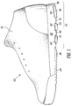
- Figure 1 is an elevational view of the lateral side of a shoe embodying the present invention;
- Figure 2 is a bottom view of the shoe shown in Figure 1;
- Figure 3 is a schematic representation of a cross-section cut along line 3-3 of Figure 2;
- Figure 3A is a cross-section of another embodiment of the invention;
- Figure 3B is a cross-section of another embodiment of the invention;
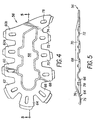
- Figure 4 is a top plan view of one insert member of the present invention;
- Figure 5 is a side view of the insert member shown in Figure 4;
- Figure 6 is the bottom of a heel showing another embodiment of the invention;
- Figure 7 is a cross-sectional view of Figure 6 cut along lines 7-7;
- Figure 8 is a cross-section of Figure 6 cut along lines 8-8;
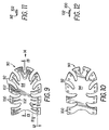
- Figure 9 is a top view of the insert used in the outsole shown in Figure 6;
- Figure 10 is a bottom view of the insert shown in Figure 9;
- Figure 11 is a view of Figure 9 cut along line 11-11;
- Figure 12 is a view of Figure 9 cut along lines 12-12;
- Figure 13 is a view of Figure 11 cut along lines 13-13;
- Figure 14 is a side view of Figure 9 looking in the direction of
arrow 14; - Figure 15 is a side of the insert shown in Figure 9;
- Figure 16 is yet another embodiment of the insert of the present invention;
- Figure 17 is a side view schematic of the insert member of Figure 20 in operation with other components;
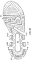
- Figure 18 is a bottom view of an outsole used for practicing the present invention;
- Figure 19 is a view of Figure 18 cut along line 19-19;
- Figure 20 is a view of Figure 18 cut along line 20-20; and
- Figure 21 is a view of Figure 18 cut along line 21-21.
- Referring first to Figures 1-3, there is shown an athletic shoe which has improved energy return, memory characteristics and increased durability. A shoe, designated generally as 20, is made of a number of component parts which include an upper 22 and a sole 24. In the present invention, any conventional upper 22 may be used to practice the invention. Although an athletic shoe is shown in Figure 1, and the specification is directed in particular to athletic shoes, it is contemplated that the invention may be used on a number of different categories of shoes or boots, for example, hiking boots, casual shoes and the like. The upper 22 is attached to a sole 24 in any conventional manner. The sole 24 is made up of an
outsole 26 made of a material which is wear resistant and provides traction. As with conventional outsoles, it may be made of any abrasive resistant material such as rubber or the like. Amidsole 28 is disposed generally betweenoutsole 26 and upper 22.Midsole 28 may take on a number of forms and modifications as an artisan in the field of shoes will readily recognize. For example,midsole 28 may be made from a single material or several different materials, each having different characteristics such as density and rebound characteristics. The main purpose ofmidsole 28 is for cushioning and it may be made of a number of different materials, for example, ethyl vinyl acetate, polyurethane, or a combination thereof. In addition,midsole 28 may include a heel wedge. - The heel region of the shoe, designated as 30, is that portion of the shoe which underlies the heel of a wearer. While
heel region 30 ofshoe 20 has no precise borders, it generally may be considered as that half of the shoe away from the toe of a wearer. Although the term "heel region" is used throughout this specification, it should be noted that this region may extend into what is traditionally known as the arch area of the shoe and may in fact extend well beyond what might traditionally be characterized as the heel. - In
heel region 30 ofoutsole 26, there are a plurality of lugs 32-46 (Fg. 2) which extend downwardly from a central heel portion 47 (Fig. 3) of theheel region 30. Lugs 32-46 are preferably arranged in a cantilever configuration and thus maintain thecentral heel portion 47 at a spaced relationship to the ground. This is best seen in Figure 3 which illustrates that thecentral heel portion 47 is prevented from contacting the ground.Sole 24 is shown in an unloaded condition in this figure. In a preferred embodiment of the invention, lugs 32-46 are designed to flare outwardly to change the direction of forces which are disposed substantially perpendicular to the heel. To highlight the importance of redirecting forces, a runner may generate, upon foot strike, forces which are up to three times the runner's body weight. If these extreme forces are not dissipated, a runner may face serious and debilitating injuries. Typically, forces generated during running or other activities are not precisely perpendicular to the heel. During heel strike, for example, the lateral side of a shoe makes contact with the ground first and the shoe then rotates before toe-off. Different sports generate varying forces at various angles to a shoe. The above-described cantilever outsole serves to redirect forces irrespective of the precise angle of incidence upon a shoe. This cantilever outsole concept is more fully disclosed in U.S. Patent No. 4,372,058 to Stubblefield, the disclosure of which is expressly incorporated herein by reference. - Each of the lugs 32-46 on
outsole 26 have aland 48 for contacting the ground. Theselands 48 are configured to make contact with the ground and preferably have a roughened surface to provide traction.Lands 48 may consist of a flat surface as shown in Figure 2 and 3 or may be a point or small area. Each of the lugs 32-46 may have an angledarea 50 which leads from thecentral heel portion 47 to thelands 48. It is preferred that thisangled area 50 is a gradual angle as shown in Figure 3, but it may also be vertical. In the embodiment of the invention shown in Figure 2, wedge-shapedportions 28′ ofmidsole 28 extend between lugs 32-46. The spacing 52 between adjacent lugs enables lugs 32-46 to act more independently of each other. - Although the lugs in the accompanying drawings are shown to be separate and distinct members, it is contemplated that the heel portion of the outsole may form a concavity, without individual lugs. In other words, instead of distinct, individual lugs such as the eight lugs 32-46 shown in Figure 2, there may be a single "lug" which extends from the medial side of the shoe, around the heel, to the lateral side of the heel.
-
Outsole 26 may include a cut-out 54 in substantially thecentral heel portion 47 of the outsole. Cut-out 54 is provided primarily to reduce the weight ofoutsole 26 by eliminating material which is not necessary. Becausecentral heel portion 47 never makes contact with the ground, there is no need for the abrasive resistant material of the outsole to be present in that area. By having a cut-out 54, the overall weight of the shoe is reduced without reducing stability. In addition, the outsole may extend up along the side of the midsole for, e.g. basketball shoes and the like. - The present invention comprises a configuration of components to improve the rebound characteristics of a sole and to provide improved stability. To achieve this, an
insert member 56 is generally used in conjunction with the abovementioned shoe components to provide additional stability and memory characteristics to the sole of the shoe. Theinsert member 56 helps to increase the life of a shoe. The insert member while having a long life itself also helps prevent a midsole material from breakdown due to fatigue. A long life and decreased break down due to fatigue is possible because it is the insert which absorbs and transmits most of the generated forces. In addition, the insert member allows a midsole to recover to a relaxed state between strides. In running, for example, a runner while jogging may take one hundred strides per minute. While most midsoles cannot recover fully between strides, the present invention will enable a midsole to make such a recovery. - The
insert member 56, which may be positioned in a number of different locations as will be amplified below, enhances the overall stability of sole 24 and works in conjunction with the other component parts of sole 24. Generally,insert member 56 is positioned either sandwiched between theoutsole 26 and themidsole 28, encapsulated within themidsole 28 or encapsulated withinoutsole 26. - In Figure 3A, an alternative embodiment of the invention is shown. This embodiment is a similar view as Figure 3, but shows an alternative position of
insert member 56. In this embodiment, theinsert member 56 makes contact with both theoutsole 26 and a lasting board which is typically placed above the midsole in a conventional athletic shoe. This configuration provides for an efficient use of the invention, since there is no midsole material, e.g., polyurethane, above theinsert member 56 along the longitudinal centerline of the heel region of the shoe. - In Figure 3B, yet another embodiment of the invention is depicted. In this cross-sectional view, it is seen that
outsole 26 extends up the side ofmidsole 28. The outsole may extend upward onto the midsole around the entire heel of the shoe, if desired. - In a preferred embodiment of the invention as illustrated in Figures 4 and 5,
insert member 56 has acentral body portion 58 and a plurality of insert extensions 60-72 which extend outwardly and downwardly fromcentral body portion 58. In general, insert extensions 60-74 have aflat section 75 at the distal ends thereof (seen best in Figures 3 and 5). It should be noted that theinsert member 56 illustrated in Figure 4 utilizes ten insert extensions, while the insert member of Figures 1-3 utilizes eight insert extensions. For convenience, the additional two insert extensions ofmember 56 of Figure 4 have been designated 60a and 60b. In operation, the number of insert extensions may be varied as needed to most effectively operate in conjunction with the other component parts of the sole. - The rebound characteristics of the
insert member 56 can be controlled by varying a number of different parameters. For example, some or all of the insert extensions 60-74 may defineopenings 78 or may be built up.Openings 78 increase flexibility of an individual insert extension and decrease the weight of theinsert 56. - A number of different conventional materials are available for making
insert member 56. Examples of possible materials include: Zytel, a polyamide which may be glass reinforced with, for example, 18% glass; Delrin; Rynite; Hytrel; or a combination of the above materials such as a Hytrel/Rynite mixture. Zytel, Delrin, Rynite and Hytrel are all manufactured by DuPont. Hytrel is a semicrystalline and fully polymerized, high molecular weight, chemically stable, thermoplastic polyester elastomer composed of alternate amorphous and crystalline chains. - The above materials are intended to be illustrative of some of the possible materials for use in
insert member 56. This list is not exhaustive or comprehensive and it should be understood that many different materials may be used to practice the invention. In general, the common denominator of the materials which may be utilized to embody the invention is that the material must have good memory characteristics, that is, the material must tend to return to its original shape after deformation. In addition, the material must be durable and must not be brittle; otherwise, it may not be able to withstand the constant cycling of the material without cracking or breaking. The material used for making the insert member may be harder than the midsole material, but need not be harder. Since the hardness of the insert member as well as its thickness may be modified to achieve a desired response, there may be circumstances whereby a relativelysoft insert member 56 is utilized. The invention can be modified and tuned for the different requirements of different sports.Insert member 56 is preferably disposed in a location which will allow the insert member to cooperate with the other shoe components. This location is not limited to being next to or juxtaposed to the outsole. Theinsert member 56 may cooperate with the outsole if it is encapsulated within the midsole, sandwiched between the midsole and the outsole, or encapsulated within the outsole. The insert member may also be partially encapsulated within the midsole. In the embodiment of the invention shown in Figures 1-3,insert member 56 lies betweenoutsole 26 andmidsole 28. It may be attached to the outsole and midsole in any conventional manner. For example, the insert member may be cemented to the outsole. Ifinsert member 56 is disposed directly aboveoutsole 26, the central portion of the insert member may be exposed through cut-out 54 inoutsole 26 as shown in Figure 2. The insert extensions 60-74 positionally correspond to lugs 32-46 inoutsole 26 and cooperate therewith to provide increased stability and rebound characteristics for sole 24. The insert extensions 60-74 have aflat section 75 which positionally correspond tolands 48 in the outsole. In operation,insert member 56 and insert extensions 60-74 cooperate with lugs 32-46 and move outward as forces impinge on the sole. In this specification, the term "outward" is used to mean that direction which is away from the central portion of the shoe in the plane defined generally by the outsole. This direction is locally the direction perpendicular to a line which is tangent to the perimeter of the outsole. In Figures 2 and 3, "outward" is the direction shown byarrows 77. Conversely, "inward" is the direction toward the central portion of the shoe. Generally speaking, acurved portion 76 connects theflat portion 75 of insert extensions 60-74 tocentral body 58 ofinsert member 56.Member 56 may be tailored to specific needs by addingadditional openings 78 or by building up sections of the extensions as desired. Additional apertures will increase the flexibility of the insert extension having the apertures. Conversely, building up an insert extension will make the insert extension more rigid. In effect, the insert member may be "tuned" by adding apertures to those extension members where additional flexibility is desired and building up those extension members where it is desirable for the extension member to be more rigid. For example, it may be desirable to have a specific area of the sole less compressible than the remaining areas of the sole. This can be accomplished by building up those extension members in the area for which less compression is desired or by adding apertures to the extension members in the area for which more compression is desired or a combination of these two approaches. - Figures 6-17 illustrate yet another embodiment of the invention. Figures 6-8 illustrate a part of a sole 80 which has an
outsole 82 and amidsole 84. As with the previously described embodiment of the invention,outsole 82 has a plurality oflugs 86 which are shaped to maintain the remaining, central portions of the sole 80 at a spaced relationship to the ground. As with other embodiments of the invention, there may be acutout 88 in the outsole. This cutout reduces the weight of the shoe by eliminating the outsole in an area it is not necessary. Figures 7-8 illustrates aninsert member 90 encapsulated withinmidsole 84. Aportion 85 ofmidsole 84 lies belowinsert member 90. By encapsulatinginsert member 90 withinmidsole 84, it is possible to improve the rebound characteristics of the sole 80 bypre-stressing insert member 90 prior to encapsulation. It should be noted, however, that prestressing of the insert member is not a requirement to practice the invention. To do so,insert member 90 is first placed in a mold, the perimeter of which is smaller at least in part than the perimeter of thepre-stressed insert member 90. By doing so,insert member 90 exerts a force against the mold and is biased in an outward direction. In Figure 8, outward is the direction depicted byarrows 104. - After
insert member 90 has been pre-stressed and placed in a mold, midsole material such as polyurethane (PU) is used to encapsulateinsert member 90. This may be done by injection molding, for example. By selecting the proper materials, the midsole maintains the insert in a loaded or stressed configuration, and thus the midsole has potential energy stored within it. - One embodiment of
insert member 90 per se is illustrated in Figures 9-15. Figure 9 is a top view ofinsert member 90 and Figure 10 is a bottom view.Insert member 90 hasinsert extensions 92 which extend outwardly from acentral body portion 94. These insertextensions 92 cooperate withlugs 86 ofoutsole 82 so that when a force impinges on the sole, bothlugs 86 and insertextensions 92 will move in an outward direction and insertextension members 92, in cooperation with the other components of the sole, will act as a spring to return the sole to its original shape. A shortened recovery time or shortened midsole cycle time is particularly important in such activities as jogging and basketball. This serves to return energy to the user without having the "mushy" feeling associated with fluid filled shoes. - It can be seen from Figure 11 that insert
extensions 92 may have a built upsection 102 which extends along the surface ofinsert extensions 92. Built upsection 102 may take on a number of different forms but is used generally to tailor the response of the midsole. Built upsection 102 gives the insert extensions more strength and less flexibility. - As with built up
section 102, insertextensions 92 may define holes orapertures 100 as shown in Figure 12.Holes 100 may be used as needed to tailor theinsert 90 to provide a desired response. Built upsection 102 andapertures 100 may be used as needed, either alone in an insert member or together. - As shown in Figures 13-15, insert
extensions 92 may have aflat portion 96 which positionally corresponds generally to that portion of theoutsole 82 which contacts the ground. Acurved portion 98 connectsflat portion 96 tocentral portion 94. - Referring now to Figures 16 and 17, yet another embodiment of the invention is shown. Figure 16 shows an
insert member 120 having an extendingportion 124, the distal end of which extends into the forefoot region of a shoe when positioned within the sole of a shoe. The outline of ashoe 123 is shown in Figure 18 to help illustrate one possible placement ofinsert member 120. The extendingportion 124 may be formed from a single piece of material such as those materials previously described for making the insert member and theinsert member 120 and extendingportion 124 are generally made from a single monolithic piece of material. It is understood, however, that it is possible to form the extendingportion 124 from separate and distinct pieces of material. - The extending
portion 124 may be formed by a plurality offingers 122 which extend generally from the remaining portion ofinsert member 120 toward the toe region ofshoe 123. - In a preferred embodiment, extending
portion 124 is made to have an undulating or sinusoidal shape in cross section (Figure 17). The undulations havepeaks 128 which make contact withoutsole 118 and spaced byvalleys 130. Thespaces 132 betweenmidsole 116 and insertmember 120, and betweenoutsole 118 and insertmember 120, are filled with air at ambient pressure. - In operation, the extending
portion 124 ofinsert member 120 acts as a spring to return energy to the user. This occurs because forces acting perpendicular to sole 118 deflect the extendingportion 124 and tend to decrease the size of thepeaks 128 andvalleys 130 when the load is placed on the extendingportion 124. Because the materials used to form extendingportion 124 have good memory characteristics, it tends to return to its original, unloaded shape. If the distal end of extendingportion 124 is not attached to either the midsole or outsole, the extendingportion 124 will increase in overall length upon loading. This occurs because the decreasing of thepeaks 128 andvalleys 130 of the undulations tend to force extendingportion 124 in the direction away from the remaining portion ofinsert member 120. - Extending
portion 124 is a feature which increases overall cushioning of the sole but does not otherwise affect the operation of the remaining portion ofinsert member 120. In other respects,insert member 120 shown in Figures 18 and 19 operates substantially the same as the insert member shown in Figure 4. - In the embodiment of the invention depicted in Figures 18-21, an insert member is substantially encapsulated by outsole material. These figures depict an
outsole 140 which has a plurality oflugs 146. Theoutsole 140 is attached to a midsole 142 (shown in phantom). Theselugs 146 work in substantially the same manner as those embodiments of the invention previously described. Theoutsole 140 includes anupper portion 148 and alower portion 150. Between the upper andlower portions insert member 144 operates in substantially the same manner in this embodiment as it does in the embodiments of the invention previously described. As seen in Figure 20 and 21,outsole 140 may define anopening 152. The upper and lower portions may be interconnected to wrap around the insert as shown in Figure 19. - The foregoing description of the preferred embodiments of the invention have been presented for purposes of illustration and description. It is not intended to be exhaustive or to limit the invention to the precise form disclosed, and obviously many modifications and variations are possible in light of the above teaching. The embodiments were chosen and described in order to best explain the principles of the invention and its practical application to thereby enable others skilled in the art to best utilize the invention in various embodiments and with various modifications as are suited to the particular use contemplated. It is intended that the scope of the invention be defined by the claims appended hereto.
Claims (33)
- An athletic shoe, comprising:a. an upper (22),b. a sole (24) attached to said upper (22), said sole (24) including:characterized in thatb₁ a midsole (28), said midsole having a top surface and a bottom surface;b₂ an outsole (26);b₃ an insert member (56), said insert member being made of a material having a hardness greater than said midsole (28);
said outsole (26) has a central heel portion (47) and a plurality of periphery lugs (32-46), said lugs being effective to contact the ground and to maintain said central heel portion (47) in a spaced-apart relationship to the ground;
and said insert member (56) has insert extensions (60-74) which cooperate with said periphery lugs (32-46). - The athletic shoe of claim 1, wherein said insert member (56) is positioned between said outsole (26) and said midsole (28).
- The athletic shoe of claim 1, wherein said insert member (56) is encapsulated in said midsole (28).
- The athletic shoe of claim 1, wherein said insert member (56) is partially encapsulated in said midsole (28).
- The athletic shoe of any of claims 1 to 4, wherein said central heel portion (47) defines an opening (54).
- The athletic shoe of claim 5, wherein the opening (54) defined by said outsole (28) exposes said insert member (56).
- The athletic shoe of claim 1, wherein said periphery lugs (32-46) extend downwardly and outwardly from the central heel portion (47).
- The athletic shoe of claim 7, wherein said insert extensions (60-74) extend downwardly and outwardly.
- The athletic shoe of claim 7, wherein the lower surface of said midsole (28) extends between said periphery lugs (32-46).
- The athletic shoe of claim 1, wherein said insert member (56) has a substantially planar body portion (58) and wherein said insert extensions (60-74) extend downwardly from said body portion (58).
- The athletic shoe of claim 1, wherein said insert member (56) comprises a polymeric material.
- The athletic shoe of claim 11, wherein said insert member (56) comprises a semicrystalline and fully polymerized, high molecular weight, thermoplastic polyester elastomer composed of alternate amorphous and crystalline chains, preferably HYTREL.
- The athletic shoe of claim 11, wherein said insert member (56) comprises a polyacetal polymer, like e.g. polyoxymethylene, preferably DELRIN.
- The athletic shoe of claim 11, wherein said insert member (56) comprises a thermoplastic polymer, like e.g. a polybutylene terephtalate, preferably RYNITE.
- The athletic shoe of claim 11, wherein said insert member (56) comprises a combination of RYNITE and HYTREL.
- The athletic shoe of claim 11, wherein said polymeric material is glass reinforced.
- The athletic shoe of claim 16, wherein said polymeric material is a glass-reinforced polyamide, preferably ZYTEL.
- The athletic shoe of claim 11, wherein said insert member (56) comprised approximately 18% glass-reinforced ZYTEL.
- The athletic shoe of any of claims 10 to 18, wherein said insert member (56) defines a plurality of openings (78) for reducing the weight thereof.
- A shoe sole, comprising:a. an outsole (26); andb. an insert member (56),characterized in that
said outsole has a plurality of lugs (32-46), said lugs extending downwardly from the periphery of said outsole (26);
and said insert member (56) has a body portion (58) and at least one insert extension (60-74) extending from said body portion, wherein said at least one insert extension is positioned above at least one of said lugs. - The shoe sole as defined by claim 20, further comprising a midsole (28) positioned above the body portion (58) of said insert member (56) and extending between said plurality of lugs (32-46) of said outsole.
- The shoe sole as defined by claim 20 or 21, wherein the distal end of said lugs (32-46) have lands (48) with a ground-contacting surface said ground-contacting surface of said land defining a first plane.
- An athletic shoe, comprising:a. an upper (22);b. a sole (24) attached to said upper, said sole including:characterized in thatb₁ an outsole (26) having a top surface, a bottom surface, a forefoot region, and a heel region (30);b₂ an insert member (56), said insert member being made of a material having a hardness greater than the hardness of said outsole (26);
the heel region of said outsole (26) has a periphery region for contacting the ground, and said periphery region includes a plurality of lugs (32-46) which both contact the ground and support the remaining area of said heel region (30) above the ground; and
said insert member (56) is positioned above said top surface of said outsole and comprises a plurality of insert extensions (60-74) which cooperate with said lugs (32-46) to redirect vertical forces which impinge on said outsole (26). - The athletic shoe of claim 23 wherein said heel region (30) of said outsole defines an opening.
- A method of fabricating a sole for an athletic shoe according to any preceding claim, comprising the steps of:a. preloading an insert member (56), said insert member having a body portion (58) and a plurality of extension members (60-74) extending downwardly and outwardly from said body portion (58), said preloading being effective to bias said extension members (60-74) so that said extension members exert forces in a direction away from said body portion (58);b. encapsulating said insert member (56) in a sole material, said sole material retaining said insert member (56) in a preloaded condition; andc. providing the sole with a, plurality of periphery lugs (32-46) which cooperate with said extension members (60-74).
- The method of claim 25 wherein said step of preloading an insert member (56) comprises the step of placing said insert member (56) into a mold, said mold having a width which is narrower than the insert member (56) when said insert member (56) is in an unloaded condition.
- The method of claim 26 wherein said insert member (56) comprises a material having a hardness greater than the hardness of said midsole material.
- The method of claim 27 wherein said insert member (56) comprises a polyester elastomer.
- The method of claim 28 wherein said polyester elastomer is a semicrystalline and fully polymerized, high molecular weight, thermoplastic polyester elastomer composed of alternate amorphous and crystalline chains, preferably HYTREL.
- The method of claim 27 wherein said insert member (56) comprises a polyamide.
- The method of claim 30 wherein said polyamide is a glass-reinforced polyamide, preferably ZYTEL.
- The method of any of claims 25 to 31 further comprising the step of attaching said midsole material with said insert member (56) encapsulated therein to an outsole (26).
- The method of claim 32 wherein said outsole (26) is cantilevered.
Applications Claiming Priority (2)
| Application Number | Priority Date | Filing Date | Title |
|---|---|---|---|
| US22605888A | 1988-07-29 | 1988-07-29 | |
| US226058 | 1988-07-29 |
Publications (3)
| Publication Number | Publication Date |
|---|---|
| EP0352807A2 EP0352807A2 (en) | 1990-01-31 |
| EP0352807A3 EP0352807A3 (en) | 1991-07-03 |
| EP0352807B1 true EP0352807B1 (en) | 1995-02-15 |
Family
ID=22847377
Family Applications (1)
| Application Number | Title | Priority Date | Filing Date |
|---|---|---|---|
| EP89113980A Expired - Lifetime EP0352807B1 (en) | 1988-07-29 | 1989-07-28 | Athletic shoe having an insert member |
Country Status (5)
| Country | Link |
|---|---|
| EP (1) | EP0352807B1 (en) |
| JP (1) | JPH03500377A (en) |
| CA (1) | CA1336131C (en) |
| DE (1) | DE68921111T2 (en) |
| WO (1) | WO1990001276A1 (en) |
Cited By (2)
| Publication number | Priority date | Publication date | Assignee | Title |
|---|---|---|---|---|
| US9474323B2 (en) | 2002-07-02 | 2016-10-25 | Reebok International Limited | Shoe having an inflatable bladder |
| CN104287285B (en) * | 2009-02-06 | 2017-04-12 | 耐克创新有限合伙公司 | Article of footwear with heel cushioning system |
Families Citing this family (17)
| Publication number | Priority date | Publication date | Assignee | Title |
|---|---|---|---|---|
| US5052130A (en) * | 1987-12-08 | 1991-10-01 | Wolverine World Wide, Inc. | Spring plate shoe |
| US4984376A (en) * | 1989-06-15 | 1991-01-15 | E. I. Du Pont De Nemours And Company | Midsole for footwear |
| US5381608A (en) * | 1990-07-05 | 1995-01-17 | L.A. Gear, Inc. | Shoe heel spring and stabilizer |
| CH681947A5 (en) * | 1990-10-16 | 1993-06-30 | Bernhard Georg Prof Dr M Weber | |
| US5319866A (en) * | 1991-08-21 | 1994-06-14 | Reebok International Ltd. | Composite arch member |
| US6237251B1 (en) | 1991-08-21 | 2001-05-29 | Reebok International Ltd. | Athletic shoe construction |
| US5325611A (en) * | 1992-10-19 | 1994-07-05 | Brown Group, Inc. | Comfort cradle system for footwear construction |
| US5611152A (en) * | 1995-03-02 | 1997-03-18 | Converse Inc. | Shoe sole construction containing a composite plate |
| US5729917A (en) * | 1996-01-04 | 1998-03-24 | Hyde Athletic Industries, Inc. | Combination midsole stabilizer and enhancer |
| IT242099Y1 (en) * | 1996-04-02 | 2001-06-04 | Tecnica Spa | COMPOSITE SOLE FOR SHOES IN GENERAL. |
| US5915820A (en) * | 1996-08-20 | 1999-06-29 | Adidas A G | Shoe having an internal chassis |
| US7181868B2 (en) | 2002-06-26 | 2007-02-27 | Nike, Incorporated | Article of footwear having a sole with a flex control member |
| US6892479B2 (en) | 2002-06-26 | 2005-05-17 | Nike, Inc. | Article of cleated footwear having medial and lateral sides with differing properties |
| US7219383B1 (en) | 2004-12-06 | 2007-05-22 | Anthony Ambrosini | Process for creating a pair of athletic shoes |
| US7549236B2 (en) * | 2006-03-09 | 2009-06-23 | New England Footwear, Llc | Footwear with independent suspension and protection |
| KR101412648B1 (en) * | 2013-02-14 | 2014-06-26 | 발리교역(주) | Supporting member for foot arch and insole for shoes having the same |
| US11185127B2 (en) * | 2019-08-20 | 2021-11-30 | Puma SE | Article of footwear |
Family Cites Families (20)
| Publication number | Priority date | Publication date | Assignee | Title |
|---|---|---|---|---|
| FR481026A (en) * | 1915-03-17 | 1916-10-24 | Charles Jules Marteau | Improvements in shoe manufacturing |
| US1923365A (en) * | 1931-11-11 | 1933-08-22 | Frank E Gaines | Athletic shoe |
| US2918733A (en) * | 1955-05-03 | 1959-12-29 | Anderson John Wiley | Spike anchorage in shoe bottoms |
| US3101763A (en) * | 1959-06-01 | 1963-08-27 | M & S Mfg Co | Cleat mounting washer |
| US3204347A (en) * | 1965-04-09 | 1965-09-07 | Robert B Snow | Sole plate for athletic shoe |
| FR1448107A (en) * | 1965-05-31 | 1966-08-05 | Elastic shoe heel support | |
| US3577503A (en) * | 1968-12-05 | 1971-05-04 | Usm Corp | Process of making athletic shoes with injection molded sole |
| BE791872A (en) * | 1971-11-26 | 1973-03-16 | British Bata Shoe Co Ltd | SHOE IMPROVEMENTS |
| DE2216439C3 (en) * | 1972-04-05 | 1976-01-08 | Dr.-Ing. Funck Kg, 8000 Muenchen | Shoe, in particular work or sports shoe |
| GB1378461A (en) * | 1972-12-04 | 1974-12-27 | Brooker B F | Studs for footwear |
| US4372058A (en) * | 1977-11-21 | 1983-02-08 | Stubblefield Jerry D | Shoe sole construction |
| JPS5555817A (en) * | 1978-10-19 | 1980-04-24 | Tatsuo Fukuoka | Molding die for synthetic resin |
| US4481726A (en) * | 1980-04-07 | 1984-11-13 | American Fitness, Inc. | Shoe construction |
| US4335530A (en) * | 1980-05-06 | 1982-06-22 | Stubblefield Jerry D | Shoe sole construction |
| JPS58165801A (en) * | 1982-02-10 | 1983-09-30 | トレトルン・アクチェボラーグ | Athletic shoes |
| US4854057A (en) * | 1982-02-10 | 1989-08-08 | Tretorn Ab | Dynamic support for an athletic shoe |
| US4506460A (en) * | 1982-06-18 | 1985-03-26 | Rudy Marion F | Spring moderator for articles of footwear |
| GB2156654B (en) * | 1984-04-04 | 1987-07-15 | Hi Tec Sports Ltd | Improvements in or relating to running shoes |
| DE8423344U1 (en) * | 1984-08-06 | 1984-10-31 | Puma-Sportschuhfabriken Rudolf Dassler Kg, 8522 Herzogenaurach | Shoe sole with a midsole consisting of several layers |
| US4815221A (en) * | 1987-02-06 | 1989-03-28 | Reebok International Ltd. | Shoe with energy control system |
-
1989
- 1989-07-28 WO PCT/US1989/003259 patent/WO1990001276A1/en unknown
- 1989-07-28 DE DE68921111T patent/DE68921111T2/en not_active Expired - Fee Related
- 1989-07-28 CA CA000606921A patent/CA1336131C/en not_active Expired - Fee Related
- 1989-07-28 EP EP89113980A patent/EP0352807B1/en not_active Expired - Lifetime
- 1989-07-28 JP JP1508259A patent/JPH03500377A/en active Pending
Cited By (2)
| Publication number | Priority date | Publication date | Assignee | Title |
|---|---|---|---|---|
| US9474323B2 (en) | 2002-07-02 | 2016-10-25 | Reebok International Limited | Shoe having an inflatable bladder |
| CN104287285B (en) * | 2009-02-06 | 2017-04-12 | 耐克创新有限合伙公司 | Article of footwear with heel cushioning system |
Also Published As
| Publication number | Publication date |
|---|---|
| EP0352807A2 (en) | 1990-01-31 |
| DE68921111T2 (en) | 1995-09-14 |
| EP0352807A3 (en) | 1991-07-03 |
| DE68921111D1 (en) | 1995-03-23 |
| CA1336131C (en) | 1995-07-04 |
| JPH03500377A (en) | 1991-01-31 |
| WO1990001276A1 (en) | 1990-02-22 |
Similar Documents
| Publication | Publication Date | Title |
|---|---|---|
| US5185943A (en) | Athletic shoe having an insert member in the outsole | |
| EP0352807B1 (en) | Athletic shoe having an insert member | |
| US5255451A (en) | Insert member for use in an athletic shoe | |
| US6807752B2 (en) | Sole design and structure for athletic shoe | |
| EP0878142B1 (en) | Athletic shoe midsole design and construction and process for manufacturing the same | |
| US6311414B1 (en) | Athletic shoe midsole design and construction | |
| EP0963711B1 (en) | Athletic shoe midsole design and construction | |
| US6393732B1 (en) | Athletic shoe midsole design and construction | |
| US7377057B2 (en) | Stable footwear that accommodates shear forces | |
| US6647645B2 (en) | Midsole structure of athletic shoe | |
| US6314664B1 (en) | Athletic shoe midsole design and construction | |
| EP1346655B1 (en) | Shoe sole | |
| US6295741B1 (en) | Athletic shoe sole design and construction | |
| EP1264556B1 (en) | Sole assembly for sports shoe | |
| US8544190B2 (en) | Shock absorbing device for shoe sole in rear foot part | |
| US4598487A (en) | Athletic shoes for sports-oriented activities | |
| US6497058B2 (en) | Shoe with external torsion stability element | |
| EP1894484A1 (en) | Sole structure body for shoes | |
| EP0483145B1 (en) | Insert member for use in an athletic shoe |
Legal Events
| Date | Code | Title | Description |
|---|---|---|---|
| PUAI | Public reference made under article 153(3) epc to a published international application that has entered the european phase |
Free format text: ORIGINAL CODE: 0009012 |
|
| AK | Designated contracting states |
Kind code of ref document: A2 Designated state(s): AT BE CH DE ES FR GB GR IT LI LU NL SE |
|
| RBV | Designated contracting states (corrected) |
Designated state(s): DE ES FR GB IT |
|
| PUAL | Search report despatched |
Free format text: ORIGINAL CODE: 0009013 |
|
| AK | Designated contracting states |
Kind code of ref document: A3 Designated state(s): AT BE CH DE ES FR GB GR IT LI LU NL SE |
|
| 17P | Request for examination filed |
Effective date: 19911227 |
|
| 17Q | First examination report despatched |
Effective date: 19931015 |
|
| RAP1 | Party data changed (applicant data changed or rights of an application transferred) |
Owner name: AVIA GROUP INTERNATIONAL, INC. |
|
| GRAA | (expected) grant |
Free format text: ORIGINAL CODE: 0009210 |
|
| AK | Designated contracting states |
Kind code of ref document: B1 Designated state(s): DE ES FR GB IT |
|
| PG25 | Lapsed in a contracting state [announced via postgrant information from national office to epo] |
Ref country code: IT Free format text: LAPSE BECAUSE OF FAILURE TO SUBMIT A TRANSLATION OF THE DESCRIPTION OR TO PAY THE FEE WITHIN THE PRESCRIBED TIME-LIMIT;WARNING: LAPSES OF ITALIAN PATENTS WITH EFFECTIVE DATE BEFORE 2007 MAY HAVE OCCURRED AT ANY TIME BEFORE 2007. THE CORRECT EFFECTIVE DATE MAY BE DIFFERENT FROM THE ONE RECORDED. Effective date: 19950215 Ref country code: ES Free format text: THE PATENT HAS BEEN ANNULLED BY A DECISION OF A NATIONAL AUTHORITY Effective date: 19950215 Ref country code: FR Effective date: 19950215 |
|
| REF | Corresponds to: |
Ref document number: 68921111 Country of ref document: DE Date of ref document: 19950323 |
|
| EN | Fr: translation not filed | ||
| PLBE | No opposition filed within time limit |
Free format text: ORIGINAL CODE: 0009261 |
|
| STAA | Information on the status of an ep patent application or granted ep patent |
Free format text: STATUS: NO OPPOSITION FILED WITHIN TIME LIMIT |
|
| 26N | No opposition filed | ||
| PGFP | Annual fee paid to national office [announced via postgrant information from national office to epo] |
Ref country code: GB Payment date: 19980713 Year of fee payment: 10 |
|
| PGFP | Annual fee paid to national office [announced via postgrant information from national office to epo] |
Ref country code: DE Payment date: 19980930 Year of fee payment: 10 |
|
| PG25 | Lapsed in a contracting state [announced via postgrant information from national office to epo] |
Ref country code: GB Free format text: LAPSE BECAUSE OF NON-PAYMENT OF DUE FEES Effective date: 19990728 |
|
| GBPC | Gb: european patent ceased through non-payment of renewal fee |
Effective date: 19990728 |
|
| PG25 | Lapsed in a contracting state [announced via postgrant information from national office to epo] |
Ref country code: DE Free format text: LAPSE BECAUSE OF NON-PAYMENT OF DUE FEES Effective date: 20000503 |