EP0346152A2 - Smoke detector devices and detector circuit - Google Patents
Smoke detector devices and detector circuit Download PDFInfo
- Publication number
- EP0346152A2 EP0346152A2 EP89305902A EP89305902A EP0346152A2 EP 0346152 A2 EP0346152 A2 EP 0346152A2 EP 89305902 A EP89305902 A EP 89305902A EP 89305902 A EP89305902 A EP 89305902A EP 0346152 A2 EP0346152 A2 EP 0346152A2
- Authority
- EP
- European Patent Office
- Prior art keywords
- housing
- circuit
- detector
- smoke
- alarm
- Prior art date
- Legal status (The legal status is an assumption and is not a legal conclusion. Google has not performed a legal analysis and makes no representation as to the accuracy of the status listed.)
- Withdrawn
Links
Images


Classifications
-
- G—PHYSICS
- G08—SIGNALLING
- G08B—SIGNALLING OR CALLING SYSTEMS; ORDER TELEGRAPHS; ALARM SYSTEMS
- G08B17/00—Fire alarms; Alarms responsive to explosion
- G08B17/10—Actuation by presence of smoke or gases, e.g. automatic alarm devices for analysing flowing fluid materials by the use of optical means
- G08B17/103—Actuation by presence of smoke or gases, e.g. automatic alarm devices for analysing flowing fluid materials by the use of optical means using a light emitting and receiving device
- G08B17/107—Actuation by presence of smoke or gases, e.g. automatic alarm devices for analysing flowing fluid materials by the use of optical means using a light emitting and receiving device for detecting light-scattering due to smoke
-
- G—PHYSICS
- G08—SIGNALLING
- G08B—SIGNALLING OR CALLING SYSTEMS; ORDER TELEGRAPHS; ALARM SYSTEMS
- G08B17/00—Fire alarms; Alarms responsive to explosion
- G08B17/10—Actuation by presence of smoke or gases, e.g. automatic alarm devices for analysing flowing fluid materials by the use of optical means
- G08B17/11—Actuation by presence of smoke or gases, e.g. automatic alarm devices for analysing flowing fluid materials by the use of optical means using an ionisation chamber for detecting smoke or gas
- G08B17/113—Constructional details
Definitions
- This invention relates to smoke detector devices especially, but not exclusively, for use in domestic environments.
- the present invention seeks to obviate or mitigate these disadvantages of existing smoke detectors.
- a smoke detector device is in the form of a rose plug by which an electric light bulb is suspended from a ceiling.
- the device includes a circular base 10 having fixing points 11 for attachment to a ceiling 12, a central opening 13, electrical connection points 14 to 16 for attachment of mains wires 17 and an electrical flex 18.
- the device also includes a cap 20 which is removably attached to the base, conveniently by screw threading 21 on the outer circumference of the base and the inner circumference of the cap 20.
- the cap 20 has a central opening 22 through which the flex 18 passes.
- a sleeve, not shown, may be provided to fill the opening 22 if the flex 18, is of smaller diameter than the opening.
- the cap 20 houses a smoke detector of the photoelectric-type, formed on a printed circuit board (pcb) 25, and including a sounder device 24.
- pcb printed circuit board
- a particularly preferred detector circuit is described in detail below.
- the cap may also house a 9V battery 26 to power the smoke detector means.
- the smoke detector means can be powered from the mains via a transformer not shown which reduces the voltage from 240V to 9V, in which case the battery may be omitted or retained as a stand-by power source.
- a plurality of slots 27 or other apertures are formed in the sides of the plug 20 to enable smoke to enter its interior for detection by the detector circuit.
- the sounder 24 gives an audible alarm.
- the range within which the sound can carry within a home is limited. Therefore, it is preferred that the smoke detector circuit is adapted to be connected to one or more other alarm/detector devices in other locations, such that all the alarms will sound if one detector detects smoke.
- the interconnections can be made using the earth or neutral wires of a mains ring circuit, or by means of separate wiring.
- the detector device simulates the appearance of a conventional ceiling rose plug, and by utilising the detector circuit to be described below, may be of comparable dimensions. It is therefore relatively compact and unobtrusive, and is easily fitted.
- the device may comprise a cap and base or may comprise a cap only (containing the detector circuitry etc), which is adapted to screw into an existing ceiling rose base.
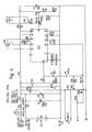
- Fig. 4 is a circuit diagram of a smoke detector circuit which may be made sufficiently small to be housed within a ceiling rose assembly of dimensions substantially the same as conventional ceiling roses, and which is relatively inexpensive to manufacture.
- the detector is of the photoelectric type, wherein light emitted by a light emitting diode Tx is detected by a phototransistor Rx, and the output from Rx is compared with a reference voltage. The presence of smoke causes reflection and scattering of the light from Tx, such that the output from Rx is increased. The alarm is thus triggered when a voltage developed from the output from Rx exceeds a predetermined threshold.
- the circuit is based around an integrated circuit IC1, and is designed to utilise miniature, surface mount components.
- the circuit may be implemented on a printed circuit board (pcb) which is small enough to be easily accommodated inside a housing of dimensions comparable to conventional ceiling rose assemblies.
- IC1 is an XCA3164M by RCA, which includes a pulse generator, comparator, and an oscillator responsive to the comparator to provide an output signal.
- IC1 generates pulses out of pin 8, whose period is set by a capacitor C3 and resistor R2, between pins 19 and 6, respectively, and ground.
- R2 is 1 Mohm, governed by the largest size available in surface mount, and C3 is 0.22 u F.
- the output of pin 8 is pulled to high voltage via resistor R7 (2.2 kohm), which is connected to the supply rail 40 either directly, via link LK2, or via a second light emitting diode, LED2. If installed, LED2 provides a flashing confidence light, providing an indication that the detector is operational.
- the pulsed output from pin 8 is differentiated via capacitor C5 (0.47 u F) and resistor R8 (10 ohm), to provide a sharp, driving pulse to transistor TR2.
- capacitor C1 (10 u F) discharges through current limiting resistor R10 (10 ohm) and the light emitting diode Tx.
- Resistor R6 (18 ohms) recharges C1 from the supply during the quiet period, and provides isolation from the sensing stage of the circuit. Tx thus provides a periodic, pulsed light signal.
- the voltage developed across R1 drives a diode pump circuit formed by diode D1 and capacitor C2 (10 nF), which in turn applies a voltage to one side of the comparator incorporated in IC1, via pin 5.
- This voltage is normally nearly zero, but increases rapidly up to the supply voltage level if smoke is present.
- a constant, reference voltage from pin 1 is divided via resistors R12 (480 kohms) and R13 (100 kohms), and connected to the other side of the comparator via pin 3.
- the ratio of the resistances of R12 and R13 determines the sensitivity of the circuit, and keeping pin 3 near zero volts ensures early triggering of the circuit in the presence of smoke.
- IC1 When the voltage at pin 5 exceeds that at pin 3, IC1 produces an enabling oscillation on pins 13, 12 and 10, which, via feedback resistors R4 (68 ohms) and R5 (27 kohms), causes oscillation of a piezoelectric sounder PZ1 connected to these three pins.
- Pin 15 of IC1 is an input/output pin which serves as an interconnect to other detector units and/or other components of an alarm system. Triggering of the circuit causes a signal to be output from pin 15, which may be used to trigger other, similar units or to operate a relay or the like (not shown), forming part of an alarm system. Conversely, a suitable signal input to pin 15 (eg from another detector unit) will trigger the circuit and activate the sounder PZ1.
- Pin 15 is connected to interconnect circuitry which includes a spike filter, comprising resistor R3 (1 kohm) and capacitor C4 (0.01 u F), to prevent false triggering of the circuit by electrical noise.
- An "alarm on” indicator may be provided by light emitting diode LED3, whose operation is controlled by transistor TR3 and which will light whenever the circuit is triggered. If LED3 is not required, link LK3 is completed to connect TR3 directly to the supply rail. Resistor R15 (10 kohm) limits the current through TR3 and LED3 (when installed).
- pin 15 should be connected to the interconnect terminal A via R3, and link LK4 should be open-circuited.
- R3 and R16 should be omitted, link LK4 should be completed, and a suitable relay connected across terminals AB.
- the circuit is further adapted to receive power from a variety of sources.
- a 9 volt battery 42 can be connected between ground and diode D3.
- a 9.1 volt zener diode D2 limits the supply to IC1 to below its maximum value of 11 volts, and capacitor decoupling is provided by capacitor C6 (100 u F).
- D3 acts as a directional diode in the event of the battery 42 acting as a standby supply for other power sources.
- Such other sources are connected to the supply rail 40 via capacitor C7 (0.01 u F, 1kV), diode D4 (peak inverse voltage 400V) and resistor Rl4.
- C7 acts as a smoothing capacitor for A.C. supplies, in which case D4 acts as a half-wave rectifier. With D.C. inputs, C7 is omitted or shorted out by link LK1, in which case D4 acts as a directional diode.
- the value of R14 depends upon the applied voltage; eg 100 ohms for 12V D.C. 500 ohms for 24V D.C. and 2.2 kohms for 240 V A.C. Any reasonable A.C.
- a transformer (not shown) could also be connected to the mains supply to provide a 9V A.C. supply, which would again be rectified by D4 and smoothed by C7. In order to prevent runaway current, R14 would have a value of 50 ohms.
- D3 could be omitted or shorted out and D2, C7, D4 and Rl4 omitted. If no standby battery is required then D3 could be omitted.
- the pcb be provided with terminals for connection of optional components such as LED2 and LED3 and links LK1 to LK4, so that a standard circuit may be produced and configured to suit particular applications.
- the pcb should be configured such that TR2 and LK2 are as close as physically possible to C1. Equally, the distances between Rx, TR1, R1, R11, D1 and C2 should be as short as possible, as should the connection between D1/C2 and pin 5 of IC1.
- the only component liable to get warm is R14, if the input voltage far exceeds its rated level. Accordingly, R14 should preferably be some distance from the other components on the pcb.
- the ground track should be as large as possible.
- the light emitting diode Tx be of the high intensity type (preferably operating in the red or near-infra-red frequency band), such as 1000 millicandela, 15mA type by Hewlett Packard, which produces approximately 300 times more light than a standard l.e.d.
- the responsive photocurrent generated by Rx is made as high as possible, so that the need for amplification of the photocurrent in the detector is reduced.
- TR1 a single transistor amplification stage, provided by TR1 is all that is required, in comparison with conventional l.e.d. detectors which generally require the use of op-amps to amplify the detected signal to a useful level.
- This reduction of the required amplification has two important benefits: it assists in reducing the component count, and hence the physical size and cost of the circuit, and it makes the circuit relatively immune to electromagnetic noise. The latter is of particular importance when the detector is installed in a ceiling rose in close proximity to A.C. mains conductors.
- the circuit hereinbefore described thus provides a smoke detector which is physically small enough to be located in a housing the size of a ceiling rose assembly, is inexpensive and reliable, and may be readily adapted to suit particular requirements. It will be appreciated that these advantages make the detector of utility in numerous situations other than in the ceiling rose application described herein.
- detector units When a plurality of such detector units are installed, for example in different rooms of a house, they may be interconnected as described above such that triggering of the detector in one room activates all the others, thereby increasing the likelihood that the occupants will be alerted.
- the interconnection may be by direct wiring of the detectors to one another, or the mains conductors of the lighting (or other) circuit may be utilised to transmit signals between the detectors in a manner that will be readily apparent to those skilled in the art.
- the housing of Figs. 1 to 3 may be further provided with suitable apertures (not shown) in its lowermost surface, into which the "confidence" and “alarm-on” l.e.d's (LED2 and LED3) may project so as to be visible from the room below.
- Figs. 5, 6 and 7 illustrate a particularly preferred embodiment of a smoke detector device in accordance with the present invention, comprising a housing 30 adapted to be mounted below an existing ceiling rose 32, in abutment therewith.
- the device preferably utilises a detector circuit as described above with reference to Fig. 4.
- the housing 30 is generally frusto-conical in shape, and includes a first, upper portion 34, and a second, lower portion 36, separated by an internal, circumferential shoulder 37.
- the electrical flex 38 depending from the ceiling rose 32 passes through the centre of the housing 30, exiting through a bushing 40 which defines a central aperture in a lowermost surface 42 closing the bottom of the second housing portion 36.
- a grub screw 44 is located in an aperture formed in the side of the bushing 40, and in use is tightened to clamp against the flex 38 and so retain the housing 30 in position below the ceiling rose 32.
- Fig. 8 illustrates an alternative, preferred clamping arrangement, wherein the external surface of the bushing 40A is slightly tapered and externally threaded, and the bushing 40A itself is divided into four segments by transverse slots 45.
- a complementary, internally tapered, internally threaded sleeve 47 screws onto the bushing 40A, deforming the segments thereof inwardly as it is tightened so as to clamp against the flex (omitted from this drawing for clarity).
- This arrangement is preferred to the grub screw 44 of Fig. 7 since its ensures that housing is centred on the flex and existing ceiling rose.
- the interior volume of the housing 30 is divided into upper and lower chambers by a circular cap 46, which is a snap-fit into the top of the lower housing portion 36, and which is provided with a central aperture to allow passage of the flex 38 therethrough.
- the upper chamber houses a battery 48 (preferably a 9V PP3 type) which provides the power supply (or stand-by power supply) for the detector, and a piezo-electric sounding device 50.
- the battery 48 and sounder 50 may be retained in position by suitable mouldings 52, 54 formed on a carrier plate 56 located on top of the cap 46, and slots 58 may be provided in the sides of the upper housing portion 34 to increase the audibility of the sounder 50.
- a tube may interconnect the interior of the upper chamber and one or more apertures (not shown) in the bottom surface 42, in which case the slots 58 may be omitted.
- the tube may be formed integrally with the carrier plate 56.
- hollow projections 59 are formed in the walls of the upper housing portion 34 to accommodate the corners of the battery 48.
- the lower chamber provides an obscuration chamber for the detector circuit, and the lower housing portion 36 is provided with slots 60 to allow smoke to enter the interior thereof.
- a pcb 62 carrying the detector circuit is located at the bottom of the obscuration chamber, mounted on the upper end of the bushing 40.
- the pcb 62 is preferably circular and is provided with a central aperture for mounting on the bushing 40 and to allow passage of the flex 38 therethrough. A further aperture would be provided to allow passage of a sounder tube, if used.
- the illuminating led and phototransistor of the detector circuit (Tx and Rx in Fig.
- Figs. 1 to 3 are disposed on the upper surface of the pcb 62 so as to detect any smoke entering the chamber, whilst the "confidence" and/or “alarm-on” led's (LED 2 and LED 3 in Fig. 4) may be disposed on the lower surface thereof, being located in apertures such as 64 formed in the lowermost surface 42 so as to be visible from the room below.
- a manual reset button 66 may also be provided in the surface 42 at a position where it co-operates with contacts (not shown) on the pcb 62 to reset the detector circuit when required.
- the housing of Figs. 1 to 3 could also incorporate such a button.
- the device of Figs. 5 to 7 may be used with ceiling roses of varying diameters the upper diameter of the housing 30 being selected to co-operate with the smallest size of ceiling rose likely to be encountered in practice (typically, 75mm is a suitable diameter).
- the arrangement whereby the device is fitted below the existing ceiling rose and clamped to the existing flex makes it simple to install, and access to the battery chamber is easily accomplished thereafter by simply loosening the clamp and sliding the housing down the flex.
- the housing 30, cap 46 and carrier plate 56 may all be moulded from plastics material, and when used in conjunction with the circuit of Fig. 4 provide a compact, unobtrusive and inexpensive detector device.
Abstract
A smoke detector device comprises a housing (30) adapted to be mounted below an existing ceiling rose fitting (32) and to be clamped to an electrical flex (38) passing therethrough. The housing (30) encloses a smoke detector circuit formed on a printed circuit board (62), a battery (48) and an alarm sounder (50). The device is intended particularly for use in domestic environment, and is intended unobtrusive and inexpensive. An alternative embodiment includes a housing adapted to replace existing ceiling rose fittings; A novel photoelectric-type detector circuit, incorporating an integrated circuit and high intensity light emitting diode, is also described, which again is intended to be compact and inexpensive.
Description
- This invention relates to smoke detector devices especially, but not exclusively, for use in domestic environments.
- The installation of smoke detectors in the home is on the increase, but in many cases the detector devices detract from the decor or are simply obvious. The detector hardware is also relatively expensive, and installation costs are often also very high. Further, if only a single detector is installed in a home it is often placed in a hallway, where fire is unlikely to start, on the grounds that if the alarm sounds during the night it will be audible in the bedrooms. It would be preferable to have multiple, interconnected detector/alarms in various locations, however the cost and visual deficiencies of existing detector means that such systems are often unfeasible or undesirable.
- The present invention seeks to obviate or mitigate these disadvantages of existing smoke detectors. In particular, it is a first object of the invention to provide a photoelectric-type smoke detector circuit which is relatively inexpensive to produce, and which is relatively compact, such that it may be enclosed in small, unobtrusive housings. It is a further object of the invention to provide a smoke detector device which forms part of a ceiling rose light fitting, and which may be either in the form of a replacement rose plug or a unit which may be mounted beneath an existing rose plug.
- These and other aspects of the invention are defined in the claims appended hereto.
- Embodiments of the invention will now be described, by way of example only, with reference to the accompanying drawings in which:
- Fig. 1 is a plan view of a base of a first smoke detector device according to the invention;
- Fig. 2 is a plan view of the cap of the smoke detector;
- Fig. 3 is a side elevation of the smoke detector in situ;
- Fig. 4 is a circuit diagram of a photoelectric-type smoke detector circuit according to another aspect of the invention;
- Fig. 5 is a side view of a second, particularly preferred smoke detector device according to the invention;
- Fig. 6 is a bottom view of the device of Fig. 5;
- Fig. 7 is a sectional view on line X-X of Fig. 6, showing the device in situ beneath an existing ceiling rose plug; and
- Fig. 8 is a detail, fragmentary, sectional view of an alternative clamping arrangement for the device of Figs. 5, 6 and 7.
- Referring to Figs. 1 to 3 of the drawings, a smoke detector device is in the form of a rose plug by which an electric light bulb is suspended from a ceiling.
- The device includes a
circular base 10 havingfixing points 11 for attachment to aceiling 12, acentral opening 13,electrical connection points 14 to 16 for attachment ofmains wires 17 and anelectrical flex 18. - The device also includes a
cap 20 which is removably attached to the base, conveniently by screw threading 21 on the outer circumference of the base and the inner circumference of thecap 20. Thecap 20 has acentral opening 22 through which theflex 18 passes. A sleeve, not shown, may be provided to fill theopening 22 if theflex 18, is of smaller diameter than the opening. - The
cap 20 houses a smoke detector of the photoelectric-type, formed on a printed circuit board (pcb) 25, and including asounder device 24. - A particularly preferred detector circuit is described in detail below.
- The cap may also house a
9V battery 26 to power the smoke detector means. Alternatively, the smoke detector means can be powered from the mains via a transformer not shown which reduces the voltage from 240V to 9V, in which case the battery may be omitted or retained as a stand-by power source. - A plurality of
slots 27 or other apertures are formed in the sides of theplug 20 to enable smoke to enter its interior for detection by the detector circuit. - When smoke is detected by the circuit, the
sounder 24 gives an audible alarm. The range within which the sound can carry within a home is limited. Therefore, it is preferred that the smoke detector circuit is adapted to be connected to one or more other alarm/detector devices in other locations, such that all the alarms will sound if one detector detects smoke. The interconnections can be made using the earth or neutral wires of a mains ring circuit, or by means of separate wiring. - The detector device simulates the appearance of a conventional ceiling rose plug, and by utilising the detector circuit to be described below, may be of comparable dimensions. It is therefore relatively compact and unobtrusive, and is easily fitted. The device may comprise a cap and base or may comprise a cap only (containing the detector circuitry etc), which is adapted to screw into an existing ceiling rose base.
- Fig. 4 is a circuit diagram of a smoke detector circuit which may be made sufficiently small to be housed within a ceiling rose assembly of dimensions substantially the same as conventional ceiling roses, and which is relatively inexpensive to manufacture. The detector is of the photoelectric type, wherein light emitted by a light emitting diode Tx is detected by a phototransistor Rx, and the output from Rx is compared with a reference voltage. The presence of smoke causes reflection and scattering of the light from Tx, such that the output from Rx is increased. The alarm is thus triggered when a voltage developed from the output from Rx exceeds a predetermined threshold.
- In order to minimise the size of the detector, the circuit is based around an integrated circuit IC1, and is designed to utilise miniature, surface mount components. The circuit may be implemented on a printed circuit board (pcb) which is small enough to be easily accommodated inside a housing of dimensions comparable to conventional ceiling rose assemblies.
- Referring to Fig. 4 in more detail, IC1 is an XCA3164M by RCA, which includes a pulse generator, comparator, and an oscillator responsive to the comparator to provide an output signal.
- IC1 generates pulses out of
pin 8, whose period is set by a capacitor C3 and resistor R2, betweenpins pin 8 is pulled to high voltage via resistor R7 (2.2 kohm), which is connected to thesupply rail 40 either directly, via link LK2, or via a second light emitting diode, LED2. If installed, LED2 provides a flashing confidence light, providing an indication that the detector is operational. The pulsed output frompin 8 is differentiated via capacitor C5 (0.47 u F) and resistor R8 (10 ohm), to provide a sharp, driving pulse to transistor TR2. when TR2 is enabled, capacitor C1 (10 u F) discharges through current limiting resistor R10 (10 ohm) and the light emitting diode Tx. Resistor R6 (18 ohms) recharges C1 from the supply during the quiet period, and provides isolation from the sensing stage of the circuit. Tx thus provides a periodic, pulsed light signal. - If smoke is present, the light emitted from Tx is reflected and scattered, and is detected by the phototransistor Rx. The photocurrent generated by Rx biases transistor TR1 on, which is otherwise held off by resistor R11 (100 kohms). A voltage is thus developed across resistor R1 (470 kohms), which is proportional to the light received by Rx. The configuration gives a gain multiplication between TR1 and Rx.
- As the illuminating light from Tx is pulsed, the voltage developed across R1 drives a diode pump circuit formed by diode D1 and capacitor C2 (10 nF), which in turn applies a voltage to one side of the comparator incorporated in IC1, via pin 5. This voltage is normally nearly zero, but increases rapidly up to the supply voltage level if smoke is present. A constant, reference voltage from
pin 1 is divided via resistors R12 (480 kohms) and R13 (100 kohms), and connected to the other side of the comparator viapin 3. The ratio of the resistances of R12 and R13 determines the sensitivity of the circuit, and keepingpin 3 near zero volts ensures early triggering of the circuit in the presence of smoke. - When the voltage at pin 5 exceeds that at
pin 3, IC1 produces an enabling oscillation onpins -
Pin 15 of IC1 is an input/output pin which serves as an interconnect to other detector units and/or other components of an alarm system. Triggering of the circuit causes a signal to be output frompin 15, which may be used to trigger other, similar units or to operate a relay or the like (not shown), forming part of an alarm system. Conversely, a suitable signal input to pin 15 (eg from another detector unit) will trigger the circuit and activate the sounder PZ1. -
Pin 15 is connected to interconnect circuitry which includes a spike filter, comprising resistor R3 (1 kohm) and capacitor C4 (0.01 u F), to prevent false triggering of the circuit by electrical noise. An "alarm on" indicator may be provided by light emitting diode LED3, whose operation is controlled by transistor TR3 and which will light whenever the circuit is triggered. If LED3 is not required, link LK3 is completed to connect TR3 directly to the supply rail. Resistor R15 (10 kohm) limits the current through TR3 and LED3 (when installed). - If the circuit is to be interconnected with other similar detectors, then pin 15 should be connected to the interconnect terminal A via R3, and link LK4 should be open-circuited. In order for a relay output to be produced, then R3 and R16 should be omitted, link LK4 should be completed, and a suitable relay connected across terminals AB.
- The circuit is further adapted to receive power from a variety of sources. A 9
volt battery 42 can be connected between ground and diode D3. A 9.1 volt zener diode D2 limits the supply to IC1 to below its maximum value of 11 volts, and capacitor decoupling is provided by capacitor C6 (100 u F). D3 acts as a directional diode in the event of thebattery 42 acting as a standby supply for other power sources. - Such other sources are connected to the
supply rail 40 via capacitor C7 (0.01 u F, 1kV), diode D4 (peak inverse voltage 400V) and resistor Rl4. C7 acts as a smoothing capacitor for A.C. supplies, in which case D4 acts as a half-wave rectifier. With D.C. inputs, C7 is omitted or shorted out by link LK1, in which case D4 acts as a directional diode. The value of R14 depends upon the applied voltage; eg 100 ohms for 12V D.C. 500 ohms for 24V D.C. and 2.2 kohms for 240 V A.C. Any reasonable A.C. voltage can be applied to D4 providing its peak inverse voltage is not exceeded. A transformer (not shown) could also be connected to the mains supply to provide a 9V A.C. supply, which would again be rectified by D4 and smoothed by C7. In order to prevent runaway current, R14 would have a value of 50 ohms. - If the unit is to be run on battery power only, then D3, could be omitted or shorted out and D2, C7, D4 and Rl4 omitted. If no standby battery is required then D3 could be omitted.
- In order to provide maximum flexibility of use, it is preferred that the pcb be provided with terminals for connection of optional components such as LED2 and LED3 and links LK1 to LK4, so that a standard circuit may be produced and configured to suit particular applications.
- For optimal circuit performance, the pcb should be configured such that TR2 and LK2 are as close as physically possible to C1. Equally, the distances between Rx, TR1, R1, R11, D1 and C2 should be as short as possible, as should the connection between D1/C2 and pin 5 of IC1. The only component liable to get warm is R14, if the input voltage far exceeds its rated level. Accordingly, R14 should preferably be some distance from the other components on the pcb. For maximum noise immunity, the ground track should be as large as possible.
- It is particularly advantageous that the light emitting diode Tx be of the high intensity type (preferably operating in the red or near-infra-red frequency band), such as 1000 millicandela, 15mA type by Hewlett Packard, which produces approximately 300 times more light than a standard l.e.d. By providing a high intensity light output from Tx, the responsive photocurrent generated by Rx is made as high as possible, so that the need for amplification of the photocurrent in the detector is reduced. Thus, a single transistor amplification stage, provided by TR1, is all that is required, in comparison with conventional l.e.d. detectors which generally require the use of op-amps to amplify the detected signal to a useful level. This reduction of the required amplification has two important benefits: it assists in reducing the component count, and hence the physical size and cost of the circuit, and it makes the circuit relatively immune to electromagnetic noise. The latter is of particular importance when the detector is installed in a ceiling rose in close proximity to A.C. mains conductors.
- The circuit hereinbefore described thus provides a smoke detector which is physically small enough to be located in a housing the size of a ceiling rose assembly, is inexpensive and reliable, and may be readily adapted to suit particular requirements. It will be appreciated that these advantages make the detector of utility in numerous situations other than in the ceiling rose application described herein.
- When a plurality of such detector units are installed, for example in different rooms of a house, they may be interconnected as described above such that triggering of the detector in one room activates all the others, thereby increasing the likelihood that the occupants will be alerted. The interconnection may be by direct wiring of the detectors to one another, or the mains conductors of the lighting (or other) circuit may be utilised to transmit signals between the detectors in a manner that will be readily apparent to those skilled in the art.
- The housing of Figs. 1 to 3 may be further provided with suitable apertures (not shown) in its lowermost surface, into which the "confidence" and "alarm-on" l.e.d's (LED2 and LED3) may project so as to be visible from the room below.
- Figs. 5, 6 and 7 illustrate a particularly preferred embodiment of a smoke detector device in accordance with the present invention, comprising a
housing 30 adapted to be mounted below an existing ceiling rose 32, in abutment therewith. The device preferably utilises a detector circuit as described above with reference to Fig. 4. - The
housing 30 is generally frusto-conical in shape, and includes a first,upper portion 34, and a second,lower portion 36, separated by an internal,circumferential shoulder 37. Theelectrical flex 38 depending from the ceiling rose 32 passes through the centre of thehousing 30, exiting through abushing 40 which defines a central aperture in alowermost surface 42 closing the bottom of thesecond housing portion 36. Agrub screw 44 is located in an aperture formed in the side of thebushing 40, and in use is tightened to clamp against theflex 38 and so retain thehousing 30 in position below the ceiling rose 32. - Fig. 8 illustrates an alternative, preferred clamping arrangement, wherein the external surface of the
bushing 40A is slightly tapered and externally threaded, and thebushing 40A itself is divided into four segments bytransverse slots 45. A complementary, internally tapered, internally threadedsleeve 47 screws onto thebushing 40A, deforming the segments thereof inwardly as it is tightened so as to clamp against the flex (omitted from this drawing for clarity). This arrangement is preferred to thegrub screw 44 of Fig. 7 since its ensures that housing is centred on the flex and existing ceiling rose. - The interior volume of the
housing 30 is divided into upper and lower chambers by acircular cap 46, which is a snap-fit into the top of thelower housing portion 36, and which is provided with a central aperture to allow passage of theflex 38 therethrough. The upper chamber houses a battery 48 (preferably a 9V PP3 type) which provides the power supply (or stand-by power supply) for the detector, and a piezo-electric sounding device 50. Thebattery 48 and sounder 50 may be retained in position bysuitable mouldings carrier plate 56 located on top of thecap 46, andslots 58 may be provided in the sides of theupper housing portion 34 to increase the audibility of the sounder 50. Alternatively, a tube (not shown) may interconnect the interior of the upper chamber and one or more apertures (not shown) in thebottom surface 42, in which case theslots 58 may be omitted. The tube may be formed integrally with thecarrier plate 56. In this example,hollow projections 59 are formed in the walls of theupper housing portion 34 to accommodate the corners of thebattery 48. - The lower chamber provides an obscuration chamber for the detector circuit, and the
lower housing portion 36 is provided withslots 60 to allow smoke to enter the interior thereof. Apcb 62 carrying the detector circuit is located at the bottom of the obscuration chamber, mounted on the upper end of thebushing 40. Thepcb 62 is preferably circular and is provided with a central aperture for mounting on thebushing 40 and to allow passage of theflex 38 therethrough. A further aperture would be provided to allow passage of a sounder tube, if used. The illuminating led and phototransistor of the detector circuit (Tx and Rx in Fig. 4) are disposed on the upper surface of thepcb 62 so as to detect any smoke entering the chamber, whilst the "confidence" and/or "alarm-on" led's (LED 2 andLED 3 in Fig. 4) may be disposed on the lower surface thereof, being located in apertures such as 64 formed in thelowermost surface 42 so as to be visible from the room below. Amanual reset button 66 may also be provided in thesurface 42 at a position where it co-operates with contacts (not shown) on thepcb 62 to reset the detector circuit when required. The housing of Figs. 1 to 3 could also incorporate such a button. - The device of Figs. 5 to 7 may be used with ceiling roses of varying diameters the upper diameter of the
housing 30 being selected to co-operate with the smallest size of ceiling rose likely to be encountered in practice (typically, 75mm is a suitable diameter). The arrangement whereby the device is fitted below the existing ceiling rose and clamped to the existing flex makes it simple to install, and access to the battery chamber is easily accomplished thereafter by simply loosening the clamp and sliding the housing down the flex. Thehousing 30,cap 46 andcarrier plate 56 may all be moulded from plastics material, and when used in conjunction with the circuit of Fig. 4 provide a compact, unobtrusive and inexpensive detector device.
Claims (22)
1. A smoke detector device which, in use, forms part of a ceiling light fitting, comprising a housing adapted to be mounted adjacent a ceiling and having an aperture in a lower-most surface thereof to allow the passage of an electrical flex therethrough, said housing enclosing smoke detector means and alarm sounder means responsive to said detector means, and said housing being of dimensions comparable to conventional ceiling rose light fittings.
2. A device as claimed in claim 1, wherein said housing is provided with a plurality of apertures whereby smoke may enter the interior thereof.
3. A device as claimed in claim 1 or claim 2, wherein said housing is formed in a shape similar to that of a conventional ceiling rose light fitting, and is adapted to be secured to a base member of an existing fitting mounted on a ceiling.
4. A device as claimed in claim 1 or claim 2, wherein said housing comprises a cap portion and a base portion, said base portion being adapted to be affixed to a ceiling and said cap portion being adapted to be secured to said base portion.
5. A device as claimed in claim 4 wherein said cap and base portions are formed in a shape similar to that of a conventional ceiling rose light fitting.
6. A device as claimed in claim 1 or claim 2, wherein said housing is adapted to be located below an existing ceiling rose light fitting.
7. A device as claimed in claim 6, wherein said housing has an upper edge adapted to seat against a bottom surface of the existing fitting and further includes means for securing the housing to an electrical flex depending from the existing fitting.
8. A device as claimed in claim 7 wherein said securing means comprises a clamp arrangement located adjacent said aperture in said lowermost surface of the housing.
9. A device as claimed in claim 6, claim 7 or claim 8, wherein said housing is divided into an upper chamber adapted to house a battery and an alarm sounder device, and a lower chamber adapted to house said detector means.
10. A device as claimed in claim 9, further including means interconnecting the interior of said upper means interconnecting the interior of said upper chamber and the exterior of the housing, whereby sound emitted by said sounder may be communicated to the exterior of the housing.
11. A device as claimed in any preceding claim, wherein said housing is provided with one or more apertures in its lowermost surface adapted to receive visual indicating means associated with said detector and alarm means.
12. A device as claimed in any preceding claim, wherein said housing is further provided with a manual reset button for resetting said detector and alarm means.
13. A smoke detector device as claimed in any preceding claim, wherein said smoke detector means comprises a detector circuit including a light emitting diode (l.e.d.), a phototransistor responsive to the light emitted by the l.e.d. and means for generating an alarm signal when the output from the phototransistor indicates the presence of smoke, said sounder means being responsive to said output signal; and wherein said circuit is formed on a printed circuit board (p.c.b.) and includes an integrated circuit incorporating a pulse generator, comparator means and means responsive to said comparator means to generate an alarm signal, said l.e.d. being driven by said pulse generator so as to produce periodic light pulses, and means being provided for applying a voltage to an input of said comparator means which is representative of the photocurrent generated by said phototransistor, such that an alarm signal is triggered if said voltage exceeds a predetermined threshold.
14. The device of claim l3, wherein said l.e.d. is a high intensity l.e.d.
15. The device of claim 14, wherein the means for applying said voltage to the comparator input comprises a single transistor amplifier stage and a diode pump circuit.
16. The device of any of claims 13 to 15, wherein said circuit further includes input voltage conversion and rectifying means.
17. The device of any of claims 13 to 16, wherein a battery provides the main or standby power supply for the circuit.
18. The device of any of claims 13 to 17, wherein said integrated circuit further includes input/output means adapted to provide an output signal when the circuit is triggered and to trigger the circuit in response to an input signal, whereby the circuit may be interconnected with other detector circuits or other components of an alarm system.
19. The device of any of claims 13 to 18, wherein a second l.e.d. is connected to said pulse generator and is located so as to provide a visual indication that the circuit is operational.
20. The device of any of claims 13 to 19, wherein the circuit further includes a third l.e.d. adapted to provide a visual indication when the circuit is triggered.
21. The device of any of claims 13 to 20, wherein said sounder is a piezoelectric sounder.
22. A smoke detector circuit as defined in any of claims 13 to 21.
Applications Claiming Priority (2)
| Application Number | Priority Date | Filing Date | Title |
|---|---|---|---|
| GB8813811 | 1988-06-10 | ||
| GB888813811A GB8813811D0 (en) | 1988-06-10 | 1988-06-10 | Smoke detector |
Publications (2)
| Publication Number | Publication Date |
|---|---|
| EP0346152A2 true EP0346152A2 (en) | 1989-12-13 |
| EP0346152A3 EP0346152A3 (en) | 1990-10-03 |
Family
ID=10638441
Family Applications (1)
| Application Number | Title | Priority Date | Filing Date |
|---|---|---|---|
| EP19890305902 Withdrawn EP0346152A3 (en) | 1988-06-10 | 1989-06-12 | Smoke detector devices and detector circuit |
Country Status (2)
| Country | Link |
|---|---|
| EP (1) | EP0346152A3 (en) |
| GB (2) | GB8813811D0 (en) |
Cited By (33)
| Publication number | Priority date | Publication date | Assignee | Title |
|---|---|---|---|---|
| GB2312312A (en) * | 1996-04-15 | 1997-10-22 | E I Tech Ltd | A mains powered alarm sensor unit having a primary battery backup |
| WO1998038608A1 (en) * | 1997-02-27 | 1998-09-03 | Fulleon Limited | Sounder |
| WO1999019666A1 (en) * | 1997-10-15 | 1999-04-22 | Hilary Elizabeth Craig | Lamp fitting and monitoring device |
| WO2000021047A1 (en) * | 1998-10-07 | 2000-04-13 | Runner & Sprue Limited | Alarm |
| WO2002073558A2 (en) * | 2001-03-10 | 2002-09-19 | Acbond Limited | Improvements in and relating to smoke detectors |
| WO2005057989A1 (en) * | 2003-11-19 | 2005-06-23 | Lawrence Kates | Repeater unit |
| US7042352B2 (en) | 2004-05-27 | 2006-05-09 | Lawrence Kates | Wireless repeater for sensor system |
| US7102505B2 (en) | 2004-05-27 | 2006-09-05 | Lawrence Kates | Wireless sensor system |
| US7102504B2 (en) | 2004-05-27 | 2006-09-05 | Lawrence Kates | Wireless sensor monitoring unit |
| US7114343B2 (en) | 2004-08-11 | 2006-10-03 | Lawrence Kates | Method and apparatus for monitoring a condenser unit in a refrigerant-cycle system |
| US7142107B2 (en) | 2004-05-27 | 2006-11-28 | Lawrence Kates | Wireless sensor unit |
| US7142123B1 (en) | 2005-09-23 | 2006-11-28 | Lawrence Kates | Method and apparatus for detecting moisture in building materials |
| US7218237B2 (en) | 2004-05-27 | 2007-05-15 | Lawrence Kates | Method and apparatus for detecting water leaks |
| US7228726B2 (en) | 2004-09-23 | 2007-06-12 | Lawrence Kates | System and method for utility metering and leak detection |
| US7424343B2 (en) | 2004-08-11 | 2008-09-09 | Lawrence Kates | Method and apparatus for load reduction in an electric power system |
| US7460006B2 (en) | 2003-11-19 | 2008-12-02 | Lawrence Kates | Conformal repeater unit |
| EP2091031A1 (en) * | 2008-02-15 | 2009-08-19 | Siemens Aktiengesellschaft | Optical smoke alarm with amplifier integrated in light receiver |
| GB2486392A (en) * | 2010-07-29 | 2012-06-20 | Neil O'neil | Domestic electricity management system |
| US8963727B2 (en) | 2004-05-27 | 2015-02-24 | Google Inc. | Environmental sensing systems having independent notifications across multiple thresholds |
| US8964338B2 (en) | 2012-01-11 | 2015-02-24 | Emerson Climate Technologies, Inc. | System and method for compressor motor protection |
| US9121407B2 (en) | 2004-04-27 | 2015-09-01 | Emerson Climate Technologies, Inc. | Compressor diagnostic and protection system and method |
| US9140728B2 (en) | 2007-11-02 | 2015-09-22 | Emerson Climate Technologies, Inc. | Compressor sensor module |
| US9285802B2 (en) | 2011-02-28 | 2016-03-15 | Emerson Electric Co. | Residential solutions HVAC monitoring and diagnosis |
| US9310094B2 (en) | 2007-07-30 | 2016-04-12 | Emerson Climate Technologies, Inc. | Portable method and apparatus for monitoring refrigerant-cycle systems |
| US9310439B2 (en) | 2012-09-25 | 2016-04-12 | Emerson Climate Technologies, Inc. | Compressor having a control and diagnostic module |
| US9551504B2 (en) | 2013-03-15 | 2017-01-24 | Emerson Electric Co. | HVAC system remote monitoring and diagnosis |
| US9638436B2 (en) | 2013-03-15 | 2017-05-02 | Emerson Electric Co. | HVAC system remote monitoring and diagnosis |
| US9765979B2 (en) | 2013-04-05 | 2017-09-19 | Emerson Climate Technologies, Inc. | Heat-pump system with refrigerant charge diagnostics |
| US9803902B2 (en) | 2013-03-15 | 2017-10-31 | Emerson Climate Technologies, Inc. | System for refrigerant charge verification using two condenser coil temperatures |
| US9823632B2 (en) | 2006-09-07 | 2017-11-21 | Emerson Climate Technologies, Inc. | Compressor data module |
| US9885507B2 (en) | 2006-07-19 | 2018-02-06 | Emerson Climate Technologies, Inc. | Protection and diagnostic module for a refrigeration system |
| US10425877B2 (en) | 2005-07-01 | 2019-09-24 | Google Llc | Maintaining information facilitating deterministic network routing |
| US10664792B2 (en) | 2008-05-16 | 2020-05-26 | Google Llc | Maintaining information facilitating deterministic network routing |
Families Citing this family (6)
| Publication number | Priority date | Publication date | Assignee | Title |
|---|---|---|---|---|
| GB9204416D0 (en) | 1992-02-29 | 1992-04-15 | Twin City Instrumentation & Eq | An alarm |
| GB9211770D0 (en) * | 1992-06-03 | 1992-07-15 | Oliver Ian P | Lighting apparatus |
| GB2290900A (en) * | 1994-06-20 | 1996-01-10 | Timothy James Shepherd | Lighting smoke alarm |
| SE512409C2 (en) * | 1997-12-11 | 2000-03-13 | Rickard Groenstedt | Suspension for fire alarms |
| GB2337841A (en) * | 1998-05-28 | 1999-12-01 | Mark Henry Herrington | Combined light bulb fitting and smoke alarm |
| GB2371666A (en) * | 2001-01-25 | 2002-07-31 | James Turner | Fire alarm and light fitting |
Citations (4)
| Publication number | Priority date | Publication date | Assignee | Title |
|---|---|---|---|---|
| US4087799A (en) * | 1976-07-08 | 1978-05-02 | Conrac Corporation | Particulate products of combustion detector employing solid state elements |
| US4090178A (en) * | 1976-08-09 | 1978-05-16 | Norris Elwood G | Combination smoke detector and lamp structure |
| GB2008871A (en) * | 1977-11-21 | 1979-06-06 | Esb Int Corp | Auxiliary lighting systems associated with an alarm system |
| US4539556A (en) * | 1983-04-15 | 1985-09-03 | Pittway Corporation | Combustion products detector with accelerated test |
Family Cites Families (3)
| Publication number | Priority date | Publication date | Assignee | Title |
|---|---|---|---|---|
| US4717910A (en) * | 1985-11-12 | 1988-01-05 | Scripps Keith A | Detector and light assembly |
| US4694285A (en) * | 1985-11-12 | 1987-09-15 | Scripps Keith A | Combination electrical light, smoke and/or heat detector |
| GB8609863D0 (en) * | 1986-04-23 | 1986-05-29 | Benson L | Fire protection device |
-
1988
- 1988-06-10 GB GB888813811A patent/GB8813811D0/en active Pending
-
1989
- 1989-06-12 GB GB8913478A patent/GB2221074A/en not_active Withdrawn
- 1989-06-12 EP EP19890305902 patent/EP0346152A3/en not_active Withdrawn
Patent Citations (4)
| Publication number | Priority date | Publication date | Assignee | Title |
|---|---|---|---|---|
| US4087799A (en) * | 1976-07-08 | 1978-05-02 | Conrac Corporation | Particulate products of combustion detector employing solid state elements |
| US4090178A (en) * | 1976-08-09 | 1978-05-16 | Norris Elwood G | Combination smoke detector and lamp structure |
| GB2008871A (en) * | 1977-11-21 | 1979-06-06 | Esb Int Corp | Auxiliary lighting systems associated with an alarm system |
| US4539556A (en) * | 1983-04-15 | 1985-09-03 | Pittway Corporation | Combustion products detector with accelerated test |
Cited By (104)
| Publication number | Priority date | Publication date | Assignee | Title |
|---|---|---|---|---|
| GB2312312A (en) * | 1996-04-15 | 1997-10-22 | E I Tech Ltd | A mains powered alarm sensor unit having a primary battery backup |
| GB2312312B (en) * | 1996-04-15 | 2000-02-09 | E I Tech Ltd | A mains powered alarm sensor unit having a primary battery backup |
| WO1998038608A1 (en) * | 1997-02-27 | 1998-09-03 | Fulleon Limited | Sounder |
| US6362726B1 (en) | 1997-02-27 | 2002-03-26 | Fulleon Limited | Sounder device which deflects sound away from a housing |
| WO1999019666A1 (en) * | 1997-10-15 | 1999-04-22 | Hilary Elizabeth Craig | Lamp fitting and monitoring device |
| WO2000021047A1 (en) * | 1998-10-07 | 2000-04-13 | Runner & Sprue Limited | Alarm |
| WO2002073558A2 (en) * | 2001-03-10 | 2002-09-19 | Acbond Limited | Improvements in and relating to smoke detectors |
| US7109874B2 (en) | 2001-03-14 | 2006-09-19 | Acbond Limited | Smoke detectors |
| WO2002073558A3 (en) * | 2001-03-14 | 2003-03-06 | Acbond Ltd | Improvements in and relating to smoke detectors |
| WO2005057989A1 (en) * | 2003-11-19 | 2005-06-23 | Lawrence Kates | Repeater unit |
| EP1909540A2 (en) * | 2003-11-19 | 2008-04-09 | Lawrence Kates | Repeater unit |
| EP1909540A3 (en) * | 2003-11-19 | 2009-03-11 | Lawrence Kates | Repeater unit |
| US7460006B2 (en) | 2003-11-19 | 2008-12-02 | Lawrence Kates | Conformal repeater unit |
| US7199701B2 (en) | 2003-11-19 | 2007-04-03 | Lawrence Kates | Repeater unit |
| US7403097B2 (en) | 2003-11-19 | 2008-07-22 | Lawrence Kates | Conformal repeater unit |
| US10335906B2 (en) | 2004-04-27 | 2019-07-02 | Emerson Climate Technologies, Inc. | Compressor diagnostic and protection system and method |
| US9669498B2 (en) | 2004-04-27 | 2017-06-06 | Emerson Climate Technologies, Inc. | Compressor diagnostic and protection system and method |
| US9121407B2 (en) | 2004-04-27 | 2015-09-01 | Emerson Climate Technologies, Inc. | Compressor diagnostic and protection system and method |
| US9872249B2 (en) | 2004-05-27 | 2018-01-16 | Google Llc | Relaying communications in a wireless sensor system |
| US10015743B2 (en) | 2004-05-27 | 2018-07-03 | Google Llc | Relaying communications in a wireless sensor system |
| US10861316B2 (en) | 2004-05-27 | 2020-12-08 | Google Llc | Relaying communications in a wireless sensor system |
| US10663443B2 (en) | 2004-05-27 | 2020-05-26 | Google Llc | Sensor chamber airflow management systems and methods |
| US10573166B2 (en) | 2004-05-27 | 2020-02-25 | Google Llc | Relaying communications in a wireless sensor system |
| US10565858B2 (en) | 2004-05-27 | 2020-02-18 | Google Llc | Wireless transceiver |
| US7218237B2 (en) | 2004-05-27 | 2007-05-15 | Lawrence Kates | Method and apparatus for detecting water leaks |
| US10395513B2 (en) | 2004-05-27 | 2019-08-27 | Google Llc | Relaying communications in a wireless sensor system |
| US7042352B2 (en) | 2004-05-27 | 2006-05-09 | Lawrence Kates | Wireless repeater for sensor system |
| US10229586B2 (en) | 2004-05-27 | 2019-03-12 | Google Llc | Relaying communications in a wireless sensor system |
| US7142107B2 (en) | 2004-05-27 | 2006-11-28 | Lawrence Kates | Wireless sensor unit |
| US9955423B2 (en) | 2004-05-27 | 2018-04-24 | Google Llc | Measuring environmental conditions over a defined time period within a wireless sensor system |
| US7102505B2 (en) | 2004-05-27 | 2006-09-05 | Lawrence Kates | Wireless sensor system |
| US7817031B2 (en) | 2004-05-27 | 2010-10-19 | Lawrence Kates | Wireless transceiver |
| US7893828B2 (en) | 2004-05-27 | 2011-02-22 | Lawrence Kates | Bi-directional hand-shaking sensor system |
| US7893827B2 (en) | 2004-05-27 | 2011-02-22 | Lawrence Kates | Method of measuring signal strength in a wireless sensor system |
| US7893812B2 (en) | 2004-05-27 | 2011-02-22 | Lawrence Kates | Authentication codes for building/area code address |
| US7936264B2 (en) | 2004-05-27 | 2011-05-03 | Lawrence Kates | Measuring conditions within a wireless sensor system |
| US7982602B2 (en) | 2004-05-27 | 2011-07-19 | Lawrence Kates | Testing for interference within a wireless sensor system |
| US9860839B2 (en) | 2004-05-27 | 2018-01-02 | Google Llc | Wireless transceiver |
| US9723559B2 (en) | 2004-05-27 | 2017-08-01 | Google Inc. | Wireless sensor unit communication triggering and management |
| US8963727B2 (en) | 2004-05-27 | 2015-02-24 | Google Inc. | Environmental sensing systems having independent notifications across multiple thresholds |
| US8963726B2 (en) | 2004-05-27 | 2015-02-24 | Google Inc. | System and method for high-sensitivity sensor |
| US7102504B2 (en) | 2004-05-27 | 2006-09-05 | Lawrence Kates | Wireless sensor monitoring unit |
| US8963728B2 (en) | 2004-05-27 | 2015-02-24 | Google Inc. | System and method for high-sensitivity sensor |
| US9474023B1 (en) | 2004-05-27 | 2016-10-18 | Google Inc. | Controlled power-efficient operation of wireless communication devices |
| US8981950B1 (en) | 2004-05-27 | 2015-03-17 | Google Inc. | Sensor device measurements adaptive to HVAC activity |
| US9007225B2 (en) | 2004-05-27 | 2015-04-14 | Google Inc. | Environmental sensing systems having independent notifications across multiple thresholds |
| US9019110B2 (en) | 2004-05-27 | 2015-04-28 | Google Inc. | System and method for high-sensitivity sensor |
| US9412260B2 (en) | 2004-05-27 | 2016-08-09 | Google Inc. | Controlled power-efficient operation of wireless communication devices |
| US9357490B2 (en) | 2004-05-27 | 2016-05-31 | Google Inc. | Wireless transceiver |
| US9318015B2 (en) | 2004-05-27 | 2016-04-19 | Google Inc. | Wireless sensor unit communication triggering and management |
| US9286787B2 (en) | 2004-05-27 | 2016-03-15 | Google Inc. | Signal strength-based routing of network traffic in a wireless communication system |
| US9286788B2 (en) | 2004-05-27 | 2016-03-15 | Google Inc. | Traffic collision avoidance in wireless communication systems |
| US9183733B2 (en) | 2004-05-27 | 2015-11-10 | Google Inc. | Controlled power-efficient operation of wireless communication devices |
| US9690307B2 (en) | 2004-08-11 | 2017-06-27 | Emerson Climate Technologies, Inc. | Method and apparatus for monitoring refrigeration-cycle systems |
| US7114343B2 (en) | 2004-08-11 | 2006-10-03 | Lawrence Kates | Method and apparatus for monitoring a condenser unit in a refrigerant-cycle system |
| US7244294B2 (en) | 2004-08-11 | 2007-07-17 | Lawrence Kates | Air filter monitoring system |
| US7275377B2 (en) | 2004-08-11 | 2007-10-02 | Lawrence Kates | Method and apparatus for monitoring refrigerant-cycle systems |
| US9086704B2 (en) | 2004-08-11 | 2015-07-21 | Emerson Climate Technologies, Inc. | Method and apparatus for monitoring a refrigeration-cycle system |
| US9046900B2 (en) | 2004-08-11 | 2015-06-02 | Emerson Climate Technologies, Inc. | Method and apparatus for monitoring refrigeration-cycle systems |
| US9304521B2 (en) | 2004-08-11 | 2016-04-05 | Emerson Climate Technologies, Inc. | Air filter monitoring system |
| US7331187B2 (en) | 2004-08-11 | 2008-02-19 | Lawrence Kates | Intelligent thermostat system for monitoring a refrigerant-cycle apparatus |
| US7343751B2 (en) | 2004-08-11 | 2008-03-18 | Lawrence Kates | Intelligent thermostat system for load monitoring a refrigerant-cycle apparatus |
| US9023136B2 (en) | 2004-08-11 | 2015-05-05 | Emerson Climate Technologies, Inc. | Method and apparatus for monitoring a refrigeration-cycle system |
| US9021819B2 (en) | 2004-08-11 | 2015-05-05 | Emerson Climate Technologies, Inc. | Method and apparatus for monitoring a refrigeration-cycle system |
| US9017461B2 (en) | 2004-08-11 | 2015-04-28 | Emerson Climate Technologies, Inc. | Method and apparatus for monitoring a refrigeration-cycle system |
| US8974573B2 (en) | 2004-08-11 | 2015-03-10 | Emerson Climate Technologies, Inc. | Method and apparatus for monitoring a refrigeration-cycle system |
| US10558229B2 (en) | 2004-08-11 | 2020-02-11 | Emerson Climate Technologies Inc. | Method and apparatus for monitoring refrigeration-cycle systems |
| US7201006B2 (en) | 2004-08-11 | 2007-04-10 | Lawrence Kates | Method and apparatus for monitoring air-exchange evaporation in a refrigerant-cycle system |
| US7424343B2 (en) | 2004-08-11 | 2008-09-09 | Lawrence Kates | Method and apparatus for load reduction in an electric power system |
| US8034170B2 (en) | 2004-08-11 | 2011-10-11 | Lawrence Kates | Air filter monitoring system |
| US7669461B2 (en) | 2004-09-23 | 2010-03-02 | Lawrence Kates | System and method for utility metering and leak detection |
| US7228726B2 (en) | 2004-09-23 | 2007-06-12 | Lawrence Kates | System and method for utility metering and leak detection |
| US10425877B2 (en) | 2005-07-01 | 2019-09-24 | Google Llc | Maintaining information facilitating deterministic network routing |
| US10813030B2 (en) | 2005-07-01 | 2020-10-20 | Google Llc | Maintaining information facilitating deterministic network routing |
| US7142123B1 (en) | 2005-09-23 | 2006-11-28 | Lawrence Kates | Method and apparatus for detecting moisture in building materials |
| US9885507B2 (en) | 2006-07-19 | 2018-02-06 | Emerson Climate Technologies, Inc. | Protection and diagnostic module for a refrigeration system |
| US9823632B2 (en) | 2006-09-07 | 2017-11-21 | Emerson Climate Technologies, Inc. | Compressor data module |
| US9310094B2 (en) | 2007-07-30 | 2016-04-12 | Emerson Climate Technologies, Inc. | Portable method and apparatus for monitoring refrigerant-cycle systems |
| US10352602B2 (en) | 2007-07-30 | 2019-07-16 | Emerson Climate Technologies, Inc. | Portable method and apparatus for monitoring refrigerant-cycle systems |
| US10458404B2 (en) | 2007-11-02 | 2019-10-29 | Emerson Climate Technologies, Inc. | Compressor sensor module |
| US9194894B2 (en) | 2007-11-02 | 2015-11-24 | Emerson Climate Technologies, Inc. | Compressor sensor module |
| US9140728B2 (en) | 2007-11-02 | 2015-09-22 | Emerson Climate Technologies, Inc. | Compressor sensor module |
| EP2091031A1 (en) * | 2008-02-15 | 2009-08-19 | Siemens Aktiengesellschaft | Optical smoke alarm with amplifier integrated in light receiver |
| US10664792B2 (en) | 2008-05-16 | 2020-05-26 | Google Llc | Maintaining information facilitating deterministic network routing |
| US11308440B2 (en) | 2008-05-16 | 2022-04-19 | Google Llc | Maintaining information facilitating deterministic network routing |
| GB2486392A (en) * | 2010-07-29 | 2012-06-20 | Neil O'neil | Domestic electricity management system |
| US9703287B2 (en) | 2011-02-28 | 2017-07-11 | Emerson Electric Co. | Remote HVAC monitoring and diagnosis |
| US10234854B2 (en) | 2011-02-28 | 2019-03-19 | Emerson Electric Co. | Remote HVAC monitoring and diagnosis |
| US9285802B2 (en) | 2011-02-28 | 2016-03-15 | Emerson Electric Co. | Residential solutions HVAC monitoring and diagnosis |
| US10884403B2 (en) | 2011-02-28 | 2021-01-05 | Emerson Electric Co. | Remote HVAC monitoring and diagnosis |
| US9876346B2 (en) | 2012-01-11 | 2018-01-23 | Emerson Climate Technologies, Inc. | System and method for compressor motor protection |
| US8964338B2 (en) | 2012-01-11 | 2015-02-24 | Emerson Climate Technologies, Inc. | System and method for compressor motor protection |
| US9590413B2 (en) | 2012-01-11 | 2017-03-07 | Emerson Climate Technologies, Inc. | System and method for compressor motor protection |
| US9310439B2 (en) | 2012-09-25 | 2016-04-12 | Emerson Climate Technologies, Inc. | Compressor having a control and diagnostic module |
| US9762168B2 (en) | 2012-09-25 | 2017-09-12 | Emerson Climate Technologies, Inc. | Compressor having a control and diagnostic module |
| US9551504B2 (en) | 2013-03-15 | 2017-01-24 | Emerson Electric Co. | HVAC system remote monitoring and diagnosis |
| US10488090B2 (en) | 2013-03-15 | 2019-11-26 | Emerson Climate Technologies, Inc. | System for refrigerant charge verification |
| US9638436B2 (en) | 2013-03-15 | 2017-05-02 | Emerson Electric Co. | HVAC system remote monitoring and diagnosis |
| US10274945B2 (en) | 2013-03-15 | 2019-04-30 | Emerson Electric Co. | HVAC system remote monitoring and diagnosis |
| US10775084B2 (en) | 2013-03-15 | 2020-09-15 | Emerson Climate Technologies, Inc. | System for refrigerant charge verification |
| US9803902B2 (en) | 2013-03-15 | 2017-10-31 | Emerson Climate Technologies, Inc. | System for refrigerant charge verification using two condenser coil temperatures |
| US10443863B2 (en) | 2013-04-05 | 2019-10-15 | Emerson Climate Technologies, Inc. | Method of monitoring charge condition of heat pump system |
| US10060636B2 (en) | 2013-04-05 | 2018-08-28 | Emerson Climate Technologies, Inc. | Heat pump system with refrigerant charge diagnostics |
| US9765979B2 (en) | 2013-04-05 | 2017-09-19 | Emerson Climate Technologies, Inc. | Heat-pump system with refrigerant charge diagnostics |
Also Published As
| Publication number | Publication date |
|---|---|
| GB8813811D0 (en) | 1988-07-13 |
| GB2221074A (en) | 1990-01-24 |
| EP0346152A3 (en) | 1990-10-03 |
| GB8913478D0 (en) | 1989-08-02 |
Similar Documents
| Publication | Publication Date | Title |
|---|---|---|
| EP0346152A2 (en) | Smoke detector devices and detector circuit | |
| US5349330A (en) | Touch programmable illumination means | |
| US5489891A (en) | Control means for lighting devices | |
| US5019805A (en) | Smoke detector with strobed visual alarm and remote alarm coupling | |
| US5457442A (en) | Remote controlled intruder detetion and warning system | |
| US7649472B1 (en) | Integrated lighting and detector units | |
| US7636049B2 (en) | Emergency notification and directional signaling apparatus | |
| US5673022A (en) | Motion sensor/photoelectric light sensor plug-in receptacle | |
| US6710553B2 (en) | Switching device for controlling a lamp from both a wall switch and the lamp's switch | |
| US4812827A (en) | Detector and light assembly | |
| US4090178A (en) | Combination smoke detector and lamp structure | |
| KR950001356B1 (en) | Test initation apparatus with continuous or pulse input | |
| US4630248A (en) | Sound activated lamp arrangement | |
| US6133839A (en) | Smoke detector apparatus with emergency escape indicator | |
| US4257039A (en) | Smoke detector | |
| US5519389A (en) | Signal synchronized digital frequency discriminator | |
| US3934145A (en) | Ionization smoke detector and alarm system | |
| US4980672A (en) | Overhead socket smoke detector with theft alarm | |
| US4839562A (en) | Electrical devices | |
| US5686884A (en) | Supervised alarm system | |
| GB2155708A (en) | Electrical devices | |
| US20080007942A1 (en) | Mountable light with integrated activation sensor | |
| US5602522A (en) | Visual signaling system | |
| US4037206A (en) | Ionization smoke detector and alarm system | |
| US4812821A (en) | Visual fire alert system |
Legal Events
| Date | Code | Title | Description |
|---|---|---|---|
| PUAI | Public reference made under article 153(3) epc to a published international application that has entered the european phase |
Free format text: ORIGINAL CODE: 0009012 |
|
| AK | Designated contracting states |
Kind code of ref document: A2 Designated state(s): AT BE CH DE ES FR GB GR IT LI LU NL SE |
|
| PUAL | Search report despatched |
Free format text: ORIGINAL CODE: 0009013 |
|
| AK | Designated contracting states |
Kind code of ref document: A3 Designated state(s): AT BE CH DE ES FR GB GR IT LI LU NL SE |
|
| STAA | Information on the status of an ep patent application or granted ep patent |
Free format text: STATUS: THE APPLICATION IS DEEMED TO BE WITHDRAWN |
|
| 18D | Application deemed to be withdrawn |
Effective date: 19910404 |