EP0343579A2 - Releasing circuit for actuating vehicular safety device - Google Patents
Releasing circuit for actuating vehicular safety device Download PDFInfo
- Publication number
- EP0343579A2 EP0343579A2 EP89109219A EP89109219A EP0343579A2 EP 0343579 A2 EP0343579 A2 EP 0343579A2 EP 89109219 A EP89109219 A EP 89109219A EP 89109219 A EP89109219 A EP 89109219A EP 0343579 A2 EP0343579 A2 EP 0343579A2
- Authority
- EP
- European Patent Office
- Prior art keywords
- circuit
- signal
- evaluating
- check signal
- evaluating circuit
- Prior art date
- Legal status (The legal status is an assumption and is not a legal conclusion. Google has not performed a legal analysis and makes no representation as to the accuracy of the status listed.)
- Granted
Links
Images


Classifications
-
- B—PERFORMING OPERATIONS; TRANSPORTING
- B60—VEHICLES IN GENERAL
- B60R—VEHICLES, VEHICLE FITTINGS, OR VEHICLE PARTS, NOT OTHERWISE PROVIDED FOR
- B60R21/00—Arrangements or fittings on vehicles for protecting or preventing injuries to occupants or pedestrians in case of accidents or other traffic risks
- B60R21/01—Electrical circuits for triggering passive safety arrangements, e.g. airbags, safety belt tighteners, in case of vehicle accidents or impending vehicle accidents
- B60R21/017—Electrical circuits for triggering passive safety arrangements, e.g. airbags, safety belt tighteners, in case of vehicle accidents or impending vehicle accidents including arrangements for providing electric power to safety arrangements or their actuating means, e.g. to pyrotechnic fuses or electro-mechanic valves
- B60R21/0173—Diagnostic or recording means therefor
-
- G—PHYSICS
- G01—MEASURING; TESTING
- G01R—MEASURING ELECTRIC VARIABLES; MEASURING MAGNETIC VARIABLES
- G01R19/00—Arrangements for measuring currents or voltages or for indicating presence or sign thereof
- G01R19/165—Indicating that current or voltage is either above or below a predetermined value or within or outside a predetermined range of values
- G01R19/16566—Circuits and arrangements for comparing voltage or current with one or several thresholds and for indicating the result not covered by subgroups G01R19/16504, G01R19/16528, G01R19/16533
- G01R19/16585—Circuits and arrangements for comparing voltage or current with one or several thresholds and for indicating the result not covered by subgroups G01R19/16504, G01R19/16528, G01R19/16533 for individual pulses, ripple or noise and other applications where timing or duration is of importance
-
- G—PHYSICS
- G01—MEASURING; TESTING
- G01R—MEASURING ELECTRIC VARIABLES; MEASURING MAGNETIC VARIABLES
- G01R31/00—Arrangements for testing electric properties; Arrangements for locating electric faults; Arrangements for electrical testing characterised by what is being tested not provided for elsewhere
- G01R31/005—Testing of electric installations on transport means
- G01R31/006—Testing of electric installations on transport means on road vehicles, e.g. automobiles or trucks
- G01R31/007—Testing of electric installations on transport means on road vehicles, e.g. automobiles or trucks using microprocessors or computers
Definitions
- the present invention relates to vehicular safety devices such as air cushions, belt tighteners or similar arrangements, and more particularly to a checking circuit for checking a defect or malfunction in a releasing circuit for the safety devices.
- a prior art checking circuit For checking a defect or malfunction in the releasing circuit, a prior art checking circuit is designed to generate a check signal for the releasing circuit therefrom and apply it to an evaluating circuit in the releasing circuit in such a manner as to render an ignition element of the safety device in an operable condition. In such a checking circuit, it is unable to detect a defect or mulfanction in a circuit between an electromechanical transducer and the evaluating circuit. It is also unable to ascertain as to whether the ignition has been properly activated or not after an accident of the vehicle.
- an object of the present invention to provide a checking circuit for the releasing circuit capable of checking a defect or malfunction in respective components of the releasing circuit before an accident of the vehicle.
- Another object of the present invention is to provide a checking circuit having the above-mentioned characteristics and capable of ascertaining after an accident as to whether a release or ignition element of the safety device has been properly activated or not.
- a releasing circuit for actuating a safety device to protect passengers of a vehicle which comprises an acceleration sensor in the form of an electromechanical transducer arranged to provide an electric acceleration signal responsive to accelerations of the vehicle and an evaluating circuit for setting a predetermined condition for activating a release element or ignition element of the safety device and responsive to the acceleration signal from the sensor for effecting the activation of the release element when the predetermined condition has been satisfied by the acceleration signal, wherein a checking circuit for the releasing circuit comprises a check signal generator for producing therefrom a check signal at a predetermined level which does not satisfy a portion of the predetermined condition for activation of the release element and for applying the check signal to a circuit between the sensor and evaluating circuit, means responsive to the check signal from the signal generator for determining as to whether or not there is a defect or malfunction in the circuit between the sensor and evaluating circuit, and means responsive to an output signal of the evaluating circuit for ascertaining as to whether or not the release element has been
- the evaluating circuit comprises first means responsive to the acceleration signal from the sensor for producing an output signal therefrom when the predetermined condition has been satisfied by the acceleration signal and second means for effecting the activation of the release element in response to the output signal from the first means, and the means responsive to the check signal is arranged to determine as to whether or not the check signal is applied at a predetermined level to the first means of the evaluating circuit.
- the checking circuit further comprises a second check signal generator for producing therefrom a second check signal capable of activating the release element under control of the evaluating circuit and for applying the second check signal to the evaluating circuit and means responsive to the second check signal from the second signal generator for determining a defect or malfunction in the evaluating circuit.
- the means responsive to the second check signal is further arranged to ascertain as to whether or not the release element is made in an operable condition in response to the second check signal under control of the evaluating circuit.
- the evaluating circuit is arranged to effect the activation of the release element when applied with the acceleration signal from the sensor at a higher level than a predetermined value for a predetermined period of time, and the first-named check signal generator is arranged to produce therefrom a check signal at a lower level than the predetermined value.
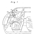
- Fig. 1 of the drawings Disclosed in Fig. 1 of the drawings is an automobile equipped with an air cushion system which includes an air bag Bg for the driver disposed within a steering wheel H, a gas generator G mounted in the air bag Bg, and a releasing circuit unit S in a control box arranged in the vehicle compartment.
- the gas generator G is provided therein with an ignition element 10 which is energized by an input current applied thereto under control of the releasing circuit to burst the gas generator for rapidly inflating the air bag Bg.
- the releasing circuit unit S includes an electromechanical transducer 20 in the form of a piezoelectric crystal for providing an electric acceleration signal responsive to accelerations of the vehicle and an evaluating circuit 30 for evaluating the acceleration signal applied thereto from transducer 20.
- a source terminal 21 of transducer 20 is connected to a voltage source in the form of a vehicle battery Ba through a fuse F and a vehicle ignition switch IG.
- An amplifier 20a is connected to an output terminal 22 of transducer 20 to amplify the electric acceleration signal applied thereto from transducer 20, and a buffer 20b is connected in series with the amplifier 20a to be conductive when biased in order by the amplified acceleration signal applied thereto from amplifier 20a. When biased in reverse, the buffer 20b becomes non-conductive.
- the evaluating circuit 30 includes a comparator 31 connected at its positive input to the buffer 20b and at its negative input to a first voltage divider composed of two resistors 31a and 31b.
- the resistors 31a and 31b are arranged to divide a source voltage (+Vc) from battery Ba into a first reference voltage which corresponds with a slightly lower value than a vehicular acceleration necessary for activating the ignition element 10.
- the comparator 31 is designed to produce a low level signal therefrom when applied with an amplified acceleration signal from buffer 20b at a lower level than the first reference voltage and to produce a high level signal therefrom when applied with an amplified acceleration signal from buffer 20b at a higher level than the first reference voltage.
- the evaluating circuit 30 further includes an integrator 32 having a capacitor 32a responsive to the high level signal from comparator 31 to be charged by the source voltage applied thereto through resistors 32b and 32c.
- the integrator 32 is arranged to produce an integrated voltage at a common terminal between the resistor 32c and capacitor 32a when charged in response to the high level signal from comparator 31.
- a comparator 33 is connected at its negative input to the integrator 32 and at its positive input to a second voltage divider composed of two resistors 33a and 33b.
- the resistors 33a and 33b are arranged to divide the source voltage (+Vc) from battery Ba into a second reference voltage which corresponds with a voltage value necessary for effecting activation of the ignition element 10.
- the comparator 33 is designed to produce a high level signal therefrom when applied with an integrated voltage from capacitor 32a at a lower level than the second reference voltage and to produce a low level signal therefrom when applied with an integrated voltage from capacitor 32a at a higher level than the second reference voltage.
- a switching circuit 40 includes a transistor 41 and a resistor 42 of high resistance disposed between the emitter and collector of transistor 41.
- the transistor 41 is connected at its base to the comparator 33 and at its emitter to the battery Ba through the vehicle ignition switch IG and fuse F.
- the collector of transistor 41 is connected to one terminal 11 of the ignition element 10.
- the transistor 41 is energized when applied with the low level signal from comparator 33 and is deenergized when applied with the high level signal from comparator 33.
- a checking circuit 50 for the releasing circuit unit S includes a comparator 51 connected at its positive input to a circuit between the amplifier 20a and buffer 20b and at its negative input to a third voltage divider composed of two resistors 51a and 51b.
- the resistors 51a and 51b are arranged to divide the source voltage into a third reference voltage.
- the comparator 51 is designed to produce a high level signal therefrom when applied with an amplified voltage from amplifier 20a at a higher level than the third reference voltage and to produce a low level signal therefrom when applied with an amplified voltage from amplifier 20a at a lower level than the third reference voltage.
- the third reference voltage is determined to be lower than an amplified voltage applied from the amplifier 20a in a condition where the level of the amplified voltage becomes lower than the first reference voltage defined by resistors 31a, 31b when the amplifier 20a has been applied with a check signal from a first check signal generator 80.
- the comparator 51 is designed to produce the high level signal therefrom when applied with the amplified check signal from signal generator 80 through amplifier 20a in a condition where the comparator 31 does not produce any high level signal therefrom even if it has been applied with the same amplified check signal from amplifier 20a through buffer 20b.
- the checking circuit 50 further includes a comparator 52 connected at its positive input to a second check signal generator 60 and at its negative input to a fourth voltage divider composed of two resistors 52a and 52b.
- the resistors 52a and 52b are arranged to divide the source voltage into a fourth reference voltage which corresponds with the third reference voltage defined by resistors 51a and 51b.
- the comparator 52 is designed to produce a high level signal therefrom when applied with a second check signal from signal generator 60 at a higher level than the fourth reference voltage.
- the checking circuit 50 further includes a comparator 53 connected at its positive input to the one terminal 11 of ignition element 10 and at its negative input to a fifth voltage divider composed of two resistors 53a and 53b.
- the resistors 53a and 53b are arranged to divide the source voltage into a fifth reference voltage.
- the comparator 53 is designed to produce a high level signal therefrom when applied with a terminal voltage of ignition element 10 at a higher level than the fifth reference voltage and to produce a low level signal therefrom when applied with a terminal voltage of ignition element 10 at a lower level than the fifth reference voltage.
- the fifth reference voltage is determined taking into consideration a ratio to the sum of resistance values of resistor 42, ignition element 10 and a resistor 72 disposed between the collector and emitter of a transistor 71 for prohibition.
- a switching circuit 70 for prohibition is composed of the transistor 71 and resistor 72.
- the transistor 71 is connected at its base to a microcomputer 54 and at its collector to the other terminal of ignition element 10. The emitter of transistor 71 is grounded.
- the ignition element 10 is maintained in a deactivated condition under control of the resistor 72 even if applied at its one terminal with the source voltage from battery Ba at a higher level than the fifth reference voltage. In such a condition, the input current to ignition element 10 is restrained in a slight value.
- the ignition element 10 is activated by the source voltage applied thereto from the battery Ba through fuse F, ignition switch IG and transistor 41.
- the checking circuit further includes a transistor 55 connected at its base to the computer 54 and at its collector to an alarm lamp La in connection to the positive terminal of battery Ba.
- the emitter of transistor 55 is connected to the negative terminal of battery Ba.
- the microcomputer 54 is arranged to cooperate with the comparators 51, 52 and 53 for execution of a computer program illustrated by a flow chart in Fig. 4.
- the computer has a read-only memory arranged to previously store the program. During execution of the program, the computer 54 carries out process control of the transistor 55, check signal generators 60, 80 and switching circuit 70 as will be described in detail later.
- the first check signal generator 80 includes a transistor 81 connected at its base to the computer 54 and at its emitter to the negative terminal of battery Ba.
- the collector of transistor 81 is connected to an input terminal of amplifier 20a through a resistor 82.
- the resistor 82 When the transistor 81 is energized under control of the computer 54, the resistor 82 generates a first check signal therefrom and applies it to the input terminal of amplifier 20a.
- the resistance value of resistor 82 is determined in such a manner that during energization of the transistor 81 the level of an amplified check signal from amplifier 20a becomes lower than the first reference voltage defined by resistors 31a, 31b and higher than the third reference voltage defined by resistors 51a, 51b.
- the check signal from resistor 82 will disappear in response to deenergization of the transistor 81.
- the second check signal generator 60 includes a transistor 61 connected at its base to the computer 54 and at its emitter to the positive terminal of battery Ba through the vehicle ignition switch IG and fuse F.
- the collector of transistor 61 is connected to the positive input of comparator 52 through a resistor 62.
- the resistor 62 When the transistor 61 is energized under control of the computer 54, the resistor 62 generates at a point 63 a second check signal therefrom at a higher level than the first, second and fourth reference voltages respectively defined by resistors 31a, 31b; 33a, 33b; and 52a, 52b.
- the second check signal from resistor 62 will disappear in response to deenergization of transistor 61.
- the computer 54 is supplied with the source current from battery Ba to initiate execution of the computer program at step 100.
- the computer 54 acts to deenergize the transistor 71 and causes the program to proceed to step 102 where it produces an output signal for energization of the transistor 81.
- both the transistors 41 and 71 are maintained in a deenergized condition, while the transistor 81 is energized in response to the output signal from computer 54 to generate a first check signal therefrom and apply it to the amplifier 20a through resistor 82.
- the buffer 20b is applied with an amplified check signal from amplifier 20a in a condition where the transducer 20 does not produce any electric acceleration signal therefrom. Since the first check signal applied through buffer 20b is maintained at a lower level than the first reference voltage, the comparator 31 produces a low level signal therefrom to maintain the transistor 41 in the deenergized condition.
- both the comparators 51 and 52 produce a high level signal therefrom.
- a circuit A including the transducer 20, amplifier 20a and buffer 20b is maintained in a normal condition. If both the comparators 51 and 52 produce a low level signal therefrom, there will be a defect or malfunction in the circuit A, for instance, disconnection between the transducer 20 and amplifier 20a.
- comparator 51 produces a high level signal therefrom while the comparator 52 produces a low level signal therefrom, there will be a defect or malfunction in an input or output circuit B of buffer 20b, for instance, disconnection of an input or output leading wire of buffer 20b.
- the computer 54 determines each level of the output signals of comparators 51 and 52. If received both the output signals of comparators 51, 52 at a low level, the computer 54 causes the program to proceed to step 104 where it determines a defect or malfunction in the circuit A. At the following step 105, the computer 54 produces a first alarm signal therefrom and applies it to the transistor 55. Thus, the transistor 55 is energized by the alarm signal from computer 54 to continuously light the alarm lamp La for informing the drive of the defect or malfunction. If received at step 103 the output signal of comparator 51 at a high level and the output signal of comparator 52 at a low level, the computer 54 causes the program to proceed to step 106 where it determines a defect or malfunction in the circuit B.
- the computer 54 intermittently produces a second alarm signal therefrom and applies it to the transistor 55.
- the transistor 55 is intermittently energized by the second alarm signal from computer 54 to intermittently light the alarm lamp La for informing the driver of the defect or malfunction in the circuit B.
- the computer 54 causes the program to proceed to step 108 where it acts to deenergize the transistor 81 and produces an output signal for energization of the transistor 61 of second check signal generator 60.
- the transistor 81 of first check signal generator 80 is maintained in a deenergized condition to make the amplified first check signal from amplifier 20a disappear, while the transistor 61 is energized in response to the output signal from computer 54 to generate a second check signal therefrom and apply it to the comparator 52 through resistor 62.
- the comparator 52 produces a high level signal therefrom.
- the comparator 33 of evaluating circuit 30 produces a low level signal therefrom in response to the second check signal applied thereto from transistor 61 through comparator 31 and integrator 32 and applies it to the transistor 41 of switching circuit 40.
- the transistor 41 is energized in response to the low level signal from comparator 33 to permit the source voltage applied to the one terminal 11 of ignition element 10 therethrough, and the comparator 53 produces a high level signal therefrom due to the terminal voltage of ignition element 10. This means that a circuit C including the evaluating circuit 30 and switching circuit 40 is maintained in a normal condition.
- the output signal of comparator 52 produces at a high level while the output signal of comparator 53 produces at a low level, there will be a defect or malfunction in the circuit C, for instance, disconnection in the evaluating circuit 30. If the comparator 51 produces a high level signal therefrom during deenergization of the transistor 81, there will be a defect or malfunction in the circuit B, for instance, short of the buffer 20b or unexpected energization of the transistor 81.
- the computer 54 determines each level of the output signals of comparators 51, 52 and 53. If received the output signal from comparator 51 at a high level, the computer 54 causes the program to proceed to step 110 where it determines a defect or malfunction in the circuit B. At the following step 107, the computer 54 intermittently produces a second alarm signal therefrom and applies it to the transistor 55. Thus, the transistor 55 is intermittently energized by the second alarm signal from computer 54 to intermittently light the alarm lamp La for informing the driver of the defect or malfunction in the circuit B.
- the computer 54 If received at step 109 the output signal from comparator 52 at a high level and the output signals from comparators 51, 53 at a low level, the computer 54 causes the program to proceed to step 111 where it determines a defect or malfunction in the circuit C.
- the computer 54 intermittently produces a third alarm signal therefrom at a different frequency from the second alarm signal and applies it to the transistor 55.
- the transistor 55 is intermittently energized by the third alarm signal from computer 54 to intermittently light the alarm lamp La for informing the drive of the defect or malfunction in the circuit C.
- the computer 54 If received at step 109 the output signal from comparator 51 at a low level and the output signals from comparators 52, 53 at a high level, the computer 54 causes the program to proceed to step 113 where it determines the fact that all the circuits A, B and C are in a normal condition.
- the computer 54 acts to deenergize the transistor 61 of check signal generator 60 and produces an output signal for energization of the transistor 71.
- the transistor 71 is energized to short the resistor 72 of switching circuit 70, and the comparator 53 is conditioned to produce a low level signal therefrom during deenergization of the transistor 41.
- the ignition element 10 is conditioned to be activated under control of the releasing circuit unit S.
- step 114 the computer 54 will repeatedly determine a "Yes” answer until it is applied with a high level signal from comparator 53. Assuming that the ignition element 10 has been activated in response to energization of the transistor 41 under control of the releasing circuit 30 to burst the gas generator G for rapidly inflating the air bag Bg, the comparator 53 produces a high level signal therefrom if it has been maintained in a normal condition. When applied with the high level signal from comparator 53, the computer 54 determines a "No" answer at step 114 and causes the program to proceed to step 114a where it determines as to whether the output signal of comparator 51 is at a high level or not. If the answer is "Yes", the computer 54 will end execution of the program.
- step 115 the computer 54 determines the fact that the ignition element 10 was properly activated by an electric acceleration signal applied to the evaluating circuit 30 through the amplifier 20a and buffer 20b without any error. If applied at step 115 with the output signal of comparator 51 at a low level and the output signal of comparator 52 at a high level, the computer 54 determines a "Yes” answer and causes the program to proceed to step 116 where it determines a defect or malfunction of transistor 61 and memorizes the same therein.
- the computer 54 determines a "No" answer and causes the program to proceed to step 117 where it determines a defect or malfunction of the transistor 41 and memorizes the same therein. Thus, it is able to ascertain as to whether or not the activation of ignition element 10 was caused by malfunction of the transistor 41 or 61 in a reliable manner.
- an electric acceleration signal from transducer 20 is amplified by the amplifier 20a and applied through buffer 20b to the evaluating circuit 30 to produce a low level signal from its comparator 33.
- the transistor 41 is energized to permit the source voltage applied therethrough to the ignition element 10 from the battery Ba.
- the ignition element 10 is properly activated to burst the gas generator G for rapidly inflating the air bag Bg.
- the checking circuit 50 is useful to ascertain a defect or malfunction in respective components of the releasing circuit unit S and to ascertain after an accident as to whether or not the ignition element 10 was properly activated in response to an electric acceleration signal from transducer 20.
- the checking circuit of the present invention has been adapted to a releasing circuit for an air cushion system, it may be adapted to a releasing circuit for a seat belt tightener or similar protective shock absorbing device.
Abstract
Description
- The present invention relates to vehicular safety devices such as air cushions, belt tighteners or similar arrangements, and more particularly to a checking circuit for checking a defect or malfunction in a releasing circuit for the safety devices.
- For checking a defect or malfunction in the releasing circuit, a prior art checking circuit is designed to generate a check signal for the releasing circuit therefrom and apply it to an evaluating circuit in the releasing circuit in such a manner as to render an ignition element of the safety device in an operable condition. In such a checking circuit, it is unable to detect a defect or mulfanction in a circuit between an electromechanical transducer and the evaluating circuit. It is also unable to ascertain as to whether the ignition has been properly activated or not after an accident of the vehicle.
- It is, therefore, an object of the present invention to provide a checking circuit for the releasing circuit capable of checking a defect or malfunction in respective components of the releasing circuit before an accident of the vehicle.
- Another object of the present invention is to provide a checking circuit having the above-mentioned characteristics and capable of ascertaining after an accident as to whether a release or ignition element of the safety device has been properly activated or not.
- According to the present invention, the foregoing objects are attained by providing a releasing circuit for actuating a safety device to protect passengers of a vehicle, which comprises an acceleration sensor in the form of an electromechanical transducer arranged to provide an electric acceleration signal responsive to accelerations of the vehicle and an evaluating circuit for setting a predetermined condition for activating a release element or ignition element of the safety device and responsive to the acceleration signal from the sensor for effecting the activation of the release element when the predetermined condition has been satisfied by the acceleration signal, wherein a checking circuit for the releasing circuit comprises a check signal generator for producing therefrom a check signal at a predetermined level which does not satisfy a portion of the predetermined condition for activation of the release element and for applying the check signal to a circuit between the sensor and evaluating circuit, means responsive to the check signal from the signal generator for determining as to whether or not there is a defect or malfunction in the circuit between the sensor and evaluating circuit, and means responsive to an output signal of the evaluating circuit for ascertaining as to whether or not the release element has been properly activated in response to the acceleration signal from the sensor under control of the evaluating circuit.
- Preferably, the evaluating circuit comprises first means responsive to the acceleration signal from the sensor for producing an output signal therefrom when the predetermined condition has been satisfied by the acceleration signal and second means for effecting the activation of the release element in response to the output signal from the first means, and the means responsive to the check signal is arranged to determine as to whether or not the check signal is applied at a predetermined level to the first means of the evaluating circuit.
- It is also preferable that the checking circuit further comprises a second check signal generator for producing therefrom a second check signal capable of activating the release element under control of the evaluating circuit and for applying the second check signal to the evaluating circuit and means responsive to the second check signal from the second signal generator for determining a defect or malfunction in the evaluating circuit. In this arrangement, the means responsive to the second check signal is further arranged to ascertain as to whether or not the release element is made in an operable condition in response to the second check signal under control of the evaluating circuit.
- In a preferred embodiment, the evaluating circuit is arranged to effect the activation of the release element when applied with the acceleration signal from the sensor at a higher level than a predetermined value for a predetermined period of time, and the first-named check signal generator is arranged to produce therefrom a check signal at a lower level than the predetermined value.
- For a better understanding of the present invention, and to show how the same may be carried into effect, reference will now be made, by way of example, to the accompanying drawings, in which:
- Fig. 1 is a partly cut away elevation of an automobile equipped with an air cushion system for the driver;
- Fig. 2 is a circuit diagram of a releasing circuit with a checking circuit in accordance with the present invention; and
- Fig. 3 is a flow chart of a program executed by a computer in the checking circuit.
- Disclosed in Fig. 1 of the drawings is an automobile equipped with an air cushion system which includes an air bag Bg for the driver disposed within a steering wheel H, a gas generator G mounted in the air bag Bg, and a releasing circuit unit S in a control box arranged in the vehicle compartment. The gas generator G is provided therein with an
ignition element 10 which is energized by an input current applied thereto under control of the releasing circuit to burst the gas generator for rapidly inflating the air bag Bg. - The releasing circuit unit S includes an
electromechanical transducer 20 in the form of a piezoelectric crystal for providing an electric acceleration signal responsive to accelerations of the vehicle and an evaluatingcircuit 30 for evaluating the acceleration signal applied thereto from transducer 20. Asource terminal 21 oftransducer 20 is connected to a voltage source in the form of a vehicle battery Ba through a fuse F and a vehicle ignition switch IG. Anamplifier 20a is connected to an output terminal 22 oftransducer 20 to amplify the electric acceleration signal applied thereto fromtransducer 20, and abuffer 20b is connected in series with theamplifier 20a to be conductive when biased in order by the amplified acceleration signal applied thereto fromamplifier 20a. When biased in reverse, thebuffer 20b becomes non-conductive. - The evaluating
circuit 30 includes acomparator 31 connected at its positive input to thebuffer 20b and at its negative input to a first voltage divider composed of tworesistors resistors ignition element 10. Thecomparator 31 is designed to produce a low level signal therefrom when applied with an amplified acceleration signal frombuffer 20b at a lower level than the first reference voltage and to produce a high level signal therefrom when applied with an amplified acceleration signal frombuffer 20b at a higher level than the first reference voltage. - The evaluating
circuit 30 further includes anintegrator 32 having acapacitor 32a responsive to the high level signal fromcomparator 31 to be charged by the source voltage applied thereto throughresistors 32b and 32c. Namely, theintegrator 32 is arranged to produce an integrated voltage at a common terminal between theresistor 32c andcapacitor 32a when charged in response to the high level signal fromcomparator 31. When applied with the low level signal fromcomparator 31, the charged voltage ofcapacitor 32a decreases in a moment. Acomparator 33 is connected at its negative input to theintegrator 32 and at its positive input to a second voltage divider composed of tworesistors 33a and 33b. Theresistors 33a and 33b are arranged to divide the source voltage (+Vc) from battery Ba into a second reference voltage which corresponds with a voltage value necessary for effecting activation of theignition element 10. Thecomparator 33 is designed to produce a high level signal therefrom when applied with an integrated voltage fromcapacitor 32a at a lower level than the second reference voltage and to produce a low level signal therefrom when applied with an integrated voltage fromcapacitor 32a at a higher level than the second reference voltage. A switching circuit 40 includes atransistor 41 and aresistor 42 of high resistance disposed between the emitter and collector oftransistor 41. Thetransistor 41 is connected at its base to thecomparator 33 and at its emitter to the battery Ba through the vehicle ignition switch IG and fuse F. The collector oftransistor 41 is connected to oneterminal 11 of theignition element 10. Thetransistor 41 is energized when applied with the low level signal fromcomparator 33 and is deenergized when applied with the high level signal fromcomparator 33. - A
checking circuit 50 for the releasing circuit unit S includes acomparator 51 connected at its positive input to a circuit between theamplifier 20a andbuffer 20b and at its negative input to a third voltage divider composed of tworesistors resistors comparator 51 is designed to produce a high level signal therefrom when applied with an amplified voltage fromamplifier 20a at a higher level than the third reference voltage and to produce a low level signal therefrom when applied with an amplified voltage fromamplifier 20a at a lower level than the third reference voltage. In this embodiment, the third reference voltage is determined to be lower than an amplified voltage applied from theamplifier 20a in a condition where the level of the amplified voltage becomes lower than the first reference voltage defined byresistors amplifier 20a has been applied with a check signal from a firstcheck signal generator 80. In other words, thecomparator 51 is designed to produce the high level signal therefrom when applied with the amplified check signal fromsignal generator 80 throughamplifier 20a in a condition where thecomparator 31 does not produce any high level signal therefrom even if it has been applied with the same amplified check signal fromamplifier 20a throughbuffer 20b. - The
checking circuit 50 further includes acomparator 52 connected at its positive input to a secondcheck signal generator 60 and at its negative input to a fourth voltage divider composed of tworesistors 52a and 52b. Theresistors 52a and 52b are arranged to divide the source voltage into a fourth reference voltage which corresponds with the third reference voltage defined byresistors comparator 52 is designed to produce a high level signal therefrom when applied with a second check signal fromsignal generator 60 at a higher level than the fourth reference voltage. - The
checking circuit 50 further includes acomparator 53 connected at its positive input to the oneterminal 11 ofignition element 10 and at its negative input to a fifth voltage divider composed of tworesistors resistors comparator 53 is designed to produce a high level signal therefrom when applied with a terminal voltage ofignition element 10 at a higher level than the fifth reference voltage and to produce a low level signal therefrom when applied with a terminal voltage ofignition element 10 at a lower level than the fifth reference voltage. In this embodiment, the fifth reference voltage is determined taking into consideration a ratio to the sum of resistance values ofresistor 42,ignition element 10 and aresistor 72 disposed between the collector and emitter of atransistor 71 for prohibition. Aswitching circuit 70 for prohibition is composed of thetransistor 71 andresistor 72. Thetransistor 71 is connected at its base to amicrocomputer 54 and at its collector to the other terminal ofignition element 10. The emitter oftransistor 71 is grounded. - Assuming that the
transistor 41 of switching circuit 40 has been energized during deenergization oftransistor 71, theignition element 10 is maintained in a deactivated condition under control of theresistor 72 even if applied at its one terminal with the source voltage from battery Ba at a higher level than the fifth reference voltage. In such a condition, the input current toignition element 10 is restrained in a slight value. When both thetransistors resistors ignition element 10 is activated by the source voltage applied thereto from the battery Ba through fuse F, ignition switch IG andtransistor 41. - The checking circuit further includes a
transistor 55 connected at its base to thecomputer 54 and at its collector to an alarm lamp La in connection to the positive terminal of battery Ba. The emitter oftransistor 55 is connected to the negative terminal of battery Ba. Themicrocomputer 54 is arranged to cooperate with thecomparators computer 54 carries out process control of thetransistor 55,check signal generators circuit 70 as will be described in detail later. - The first
check signal generator 80 includes atransistor 81 connected at its base to thecomputer 54 and at its emitter to the negative terminal of battery Ba. The collector oftransistor 81 is connected to an input terminal ofamplifier 20a through aresistor 82. When thetransistor 81 is energized under control of thecomputer 54, theresistor 82 generates a first check signal therefrom and applies it to the input terminal ofamplifier 20a. The resistance value ofresistor 82 is determined in such a manner that during energization of thetransistor 81 the level of an amplified check signal fromamplifier 20a becomes lower than the first reference voltage defined byresistors resistors resistor 82 will disappear in response to deenergization of thetransistor 81. - The second
check signal generator 60 includes atransistor 61 connected at its base to thecomputer 54 and at its emitter to the positive terminal of battery Ba through the vehicle ignition switch IG and fuse F. The collector oftransistor 61 is connected to the positive input ofcomparator 52 through aresistor 62. When thetransistor 61 is energized under control of thecomputer 54, theresistor 62 generates at a point 63 a second check signal therefrom at a higher level than the first, second and fourth reference voltages respectively defined byresistors resistor 62 will disappear in response to deenergization oftransistor 61. - Hereinafter the checking cycle of the
checking circuit 50 for the releasingcircuit 30 will be described with reference to the flow chart of Fig. 4. Assuming that the ignition switch IG has been closed to start a prime mover of the vehicle, thecomputer 54 is supplied with the source current from battery Ba to initiate execution of the computer program atstep 100. Atstep 101, thecomputer 54 acts to deenergize thetransistor 71 and causes the program to proceed to step 102 where it produces an output signal for energization of thetransistor 81. Thus, both thetransistors transistor 81 is energized in response to the output signal fromcomputer 54 to generate a first check signal therefrom and apply it to theamplifier 20a throughresistor 82. In turn, thebuffer 20b is applied with an amplified check signal fromamplifier 20a in a condition where thetransducer 20 does not produce any electric acceleration signal therefrom. Since the first check signal applied throughbuffer 20b is maintained at a lower level than the first reference voltage, thecomparator 31 produces a low level signal therefrom to maintain thetransistor 41 in the deenergized condition. - In the case that the
comparator 51 is applied with the amplified check signal fromamplifier 20a at a higher level than the thrid reference voltage defined byresisters comparator 52 is applied with the amplified check signal throughbuffer 20b at a higher level than the fourth reference voltage defined byresisters 52a, 52b, both thecomparators transducer 20,amplifier 20a andbuffer 20b is maintained in a normal condition. If both thecomparators transducer 20 andamplifier 20a. If thecomparator 51 produces a high level signal therefrom while thecomparator 52 produces a low level signal therefrom, there will be a defect or malfunction in an input or output circuit B ofbuffer 20b, for instance, disconnection of an input or output leading wire ofbuffer 20b. - When the program proceeds to step 103, the
computer 54 determines each level of the output signals ofcomparators comparators computer 54 causes the program to proceed to step 104 where it determines a defect or malfunction in the circuit A. At the followingstep 105, thecomputer 54 produces a first alarm signal therefrom and applies it to thetransistor 55. Thus, thetransistor 55 is energized by the alarm signal fromcomputer 54 to continuously light the alarm lamp La for informing the drive of the defect or malfunction. If received atstep 103 the output signal ofcomparator 51 at a high level and the output signal ofcomparator 52 at a low level, thecomputer 54 causes the program to proceed to step 106 where it determines a defect or malfunction in the circuit B. At the followingstep 107, thecomputer 54 intermittently produces a second alarm signal therefrom and applies it to thetransistor 55. Thus, thetransistor 55 is intermittently energized by the second alarm signal fromcomputer 54 to intermittently light the alarm lamp La for informing the driver of the defect or malfunction in the circuit B. - If received at
step 103 both the output signals ofcomparators computer 54 causes the program to proceed to step 108 where it acts to deenergize thetransistor 81 and produces an output signal for energization of thetransistor 61 of secondcheck signal generator 60. Thus, thetransistor 81 of firstcheck signal generator 80 is maintained in a deenergized condition to make the amplified first check signal fromamplifier 20a disappear, while thetransistor 61 is energized in response to the output signal fromcomputer 54 to generate a second check signal therefrom and apply it to thecomparator 52 throughresistor 62. When applied with the second check signal fromtransistor 61 at a higher level than the fourth reference volatge defined byresistors 52a, 52b, thecomparator 52 produces a high level signal therefrom. On the other hand, thecomparator 33 of evaluatingcircuit 30 produces a low level signal therefrom in response to the second check signal applied thereto fromtransistor 61 throughcomparator 31 andintegrator 32 and applies it to thetransistor 41 of switching circuit 40. In turn, thetransistor 41 is energized in response to the low level signal fromcomparator 33 to permit the source voltage applied to the oneterminal 11 ofignition element 10 therethrough, and thecomparator 53 produces a high level signal therefrom due to the terminal voltage ofignition element 10. This means that a circuit C including the evaluatingcircuit 30 and switching circuit 40 is maintained in a normal condition. If the output signal ofcomparator 52 produces at a high level while the output signal ofcomparator 53 produces at a low level, there will be a defect or malfunction in the circuit C, for instance, disconnection in the evaluatingcircuit 30. If thecomparator 51 produces a high level signal therefrom during deenergization of thetransistor 81, there will be a defect or malfunction in the circuit B, for instance, short of thebuffer 20b or unexpected energization of thetransistor 81. - When the program proceeds to step 109, the
computer 54 determines each level of the output signals ofcomparators comparator 51 at a high level, thecomputer 54 causes the program to proceed to step 110 where it determines a defect or malfunction in the circuit B. At the followingstep 107, thecomputer 54 intermittently produces a second alarm signal therefrom and applies it to thetransistor 55. Thus, thetransistor 55 is intermittently energized by the second alarm signal fromcomputer 54 to intermittently light the alarm lamp La for informing the driver of the defect or malfunction in the circuit B. If received atstep 109 the output signal fromcomparator 52 at a high level and the output signals fromcomparators computer 54 causes the program to proceed to step 111 where it determines a defect or malfunction in the circuit C. At the followingstep 112, thecomputer 54 intermittently produces a third alarm signal therefrom at a different frequency from the second alarm signal and applies it to thetransistor 55. Thus, thetransistor 55 is intermittently energized by the third alarm signal fromcomputer 54 to intermittently light the alarm lamp La for informing the drive of the defect or malfunction in the circuit C. - If received at
step 109 the output signal fromcomparator 51 at a low level and the output signals fromcomparators computer 54 causes the program to proceed to step 113 where it determines the fact that all the circuits A, B and C are in a normal condition. Atstep 113, thecomputer 54 acts to deenergize thetransistor 61 ofcheck signal generator 60 and produces an output signal for energization of thetransistor 71. When applied with the output signal fromcomputer 54, thetransistor 71 is energized to short theresistor 72 of switchingcircuit 70, and thecomparator 53 is conditioned to produce a low level signal therefrom during deenergization of thetransistor 41. As a result, theignition element 10 is conditioned to be activated under control of the releasing circuit unit S. - When the program proceeds to step 114, the
computer 54 will repeatedly determine a "Yes" answer until it is applied with a high level signal fromcomparator 53. Assuming that theignition element 10 has been activated in response to energization of thetransistor 41 under control of the releasingcircuit 30 to burst the gas generator G for rapidly inflating the air bag Bg, thecomparator 53 produces a high level signal therefrom if it has been maintained in a normal condition. When applied with the high level signal fromcomparator 53, thecomputer 54 determines a "No" answer atstep 114 and causes the program to proceed to step 114a where it determines as to whether the output signal ofcomparator 51 is at a high level or not. If the answer is "Yes", thecomputer 54 will end execution of the program. If the answer is "No", thecomputer 54 causes the program to proceed to step 115. When applied atstep 115 with the output signals ofcomparators computer 54 determines the fact that theignition element 10 was properly activated by an electric acceleration signal applied to the evaluatingcircuit 30 through theamplifier 20a andbuffer 20b without any error. If applied atstep 115 with the output signal ofcomparator 51 at a low level and the output signal ofcomparator 52 at a high level, thecomputer 54 determines a "Yes" answer and causes the program to proceed to step 116 where it determines a defect or malfunction oftransistor 61 and memorizes the same therein. If applied atstep 115 with the output signals ofcomparators computer 54 determines a "No" answer and causes the program to proceed to step 117 where it determines a defect or malfunction of thetransistor 41 and memorizes the same therein. Thus, it is able to ascertain as to whether or not the activation ofignition element 10 was caused by malfunction of thetransistor - Assuming that an abnormal change resulting from an accident occurs in travel speed of the vehicle during execution of the program at
step 114, an electric acceleration signal fromtransducer 20 is amplified by theamplifier 20a and applied throughbuffer 20b to the evaluatingcircuit 30 to produce a low level signal from itscomparator 33. In response to the low level signal fromcomparator 30, thetransistor 41 is energized to permit the source voltage applied therethrough to theignition element 10 from the battery Ba. Thus, theignition element 10 is properly activated to burst the gas generator G for rapidly inflating the air bag Bg. - From the above description, it will be understood that the checking
circuit 50 is useful to ascertain a defect or malfunction in respective components of the releasing circuit unit S and to ascertain after an accident as to whether or not theignition element 10 was properly activated in response to an electric acceleration signal fromtransducer 20. - Although in the above embodiment the checking circuit of the present invention has been adapted to a releasing circuit for an air cushion system, it may be adapted to a releasing circuit for a seat belt tightener or similar protective shock absorbing device.
Claims (11)
wherein a checking circuit for the releasing circuit comprises:
a check signal generator for producing therefrom a check signal at a predetermined level which does not satisfy at least a portion of the predetermined condition for activation of said release element and for applying the check signal to a circuit between said sensor and said evaluating circuit;
means responsive to the check signal from said signal generator for determining as to whether or not there is a defect or malfunction in said evaluating circuit in a condition where said evaluating circuit is being applied with the check signal; and
means responsive to an output signal of said evaluating circuit for ascertaining as to whether or not said release element has been properly activated in response to the acceleration signal from said senser under control of said evaluating circuit.
first means responsive to the acceleration signal from said sensor for producing an output signal therefrom when the predetermined condition has been satisfied by the acceleration signal, and
second means for effecting the activation of said release element in response to the output signal from said first means,
wherein said means responsive to an output signal of said evaluating means is arranged to ascertain as to whether or not said release element has been activated in response to the output signal from said first means.
first means responsive to the acceleration signal from said sensor for producing an output signal therefrom when the predetermined condition has been satisfied by the acceleration signal, and
second means for effecting the activation of said release element in response to the output signal from said first means,
wherein said means responsive to the check signal is arranged to determine as to whether or not the check signal is applied at a predetermined level to said first means of said evaluating circuit.
a second check signal generator for producing therefrom a second check signal capable of activating said release element under control of said evaluating circuit and for applying the second check signal to said evaluating circuit, and
means responsive to the second check signal from said second signal generator for determining a defect or malfunction in said evaluating circuit.
Applications Claiming Priority (2)
| Application Number | Priority Date | Filing Date | Title |
|---|---|---|---|
| JP126185/88 | 1988-05-24 | ||
| JP63126185A JPH0735142B2 (en) | 1988-05-24 | 1988-05-24 | Failure determination device for vehicle occupant protection system |
Publications (3)
| Publication Number | Publication Date |
|---|---|
| EP0343579A2 true EP0343579A2 (en) | 1989-11-29 |
| EP0343579A3 EP0343579A3 (en) | 1990-09-05 |
| EP0343579B1 EP0343579B1 (en) | 1995-06-28 |
Family
ID=14928796
Family Applications (1)
| Application Number | Title | Priority Date | Filing Date |
|---|---|---|---|
| EP89109219A Expired - Lifetime EP0343579B1 (en) | 1988-05-24 | 1989-05-23 | Releasing circuit for actuating vehicular safety device |
Country Status (4)
| Country | Link |
|---|---|
| US (1) | US5038134A (en) |
| EP (1) | EP0343579B1 (en) |
| JP (1) | JPH0735142B2 (en) |
| DE (1) | DE68923220T2 (en) |
Cited By (3)
| Publication number | Priority date | Publication date | Assignee | Title |
|---|---|---|---|---|
| EP0517253A1 (en) * | 1991-06-07 | 1992-12-09 | Kansei Corporation | Vehicle passenger restraint device for use in automotive vehicle or the like |
| EP0691244A3 (en) * | 1994-07-08 | 1996-10-09 | Telefunken Microelectron | Test method for a passive safety device in motor vehicles |
| WO2014187630A1 (en) * | 2013-05-21 | 2014-11-27 | Zf Friedrichshafen Ag | Method and circuit for assessing pulse-width-modulated signals |
Families Citing this family (17)
| Publication number | Priority date | Publication date | Assignee | Title |
|---|---|---|---|---|
| DE3841089A1 (en) * | 1988-12-07 | 1990-06-13 | Bosch Gmbh Robert | METHOD FOR EVALUATING A SENSOR SIGNAL |
| JP2905240B2 (en) * | 1990-02-07 | 1999-06-14 | アスコ株式会社 | Control system for vehicle safety equipment |
| EP0511775B1 (en) * | 1991-04-23 | 1996-11-27 | Nippondenso Co., Ltd. | Actuation system for vehicle passenger protective device |
| US5508918A (en) * | 1991-06-04 | 1996-04-16 | Automotive Systems Laboratory, Inc. | Predictor/check crash discriminator |
| US5363302A (en) * | 1991-06-04 | 1994-11-08 | Automotive Systems Laboratory, Inc. | Power rate system and method for actuating vehicle safety device |
| JPH04362443A (en) * | 1991-06-10 | 1992-12-15 | Mitsubishi Electric Corp | Occupant protection device |
| GB9121506D0 (en) * | 1991-10-10 | 1991-11-27 | Smiths Industries Plc | Resistance monitors |
| JP2692497B2 (en) * | 1992-06-29 | 1997-12-17 | 株式会社デンソー | Failure detection device for vehicle occupant protection system |
| JP2757696B2 (en) * | 1992-07-23 | 1998-05-25 | 株式会社デンソー | Failure detection device for occupant protection system |
| US5610817A (en) * | 1993-02-08 | 1997-03-11 | Breed Automotive Technology, Inc. | Passenger restraint system with an electronic crash sensor |
| JPH07291091A (en) * | 1994-04-28 | 1995-11-07 | Nippondenso Co Ltd | Malfunction preventive circuit of computer for control |
| US5519613A (en) * | 1994-10-06 | 1996-05-21 | Automotive Systems Laboratory, Inc. | System and method for discriminating short-period crashes |
| JPH10222402A (en) * | 1997-02-12 | 1998-08-21 | Nissan Motor Co Ltd | Controller for vehicle |
| JP2000272467A (en) | 1998-05-22 | 2000-10-03 | Denso Corp | Collision judge device for vehicular occupant protection system |
| US6296273B1 (en) | 2000-02-22 | 2001-10-02 | David G. Lewallen | Automobile airbag deactivation system |
| US6820557B2 (en) * | 2002-01-25 | 2004-11-23 | Daicel Chemical Industries, Ltd. | Igniter for air bag system |
| JP4614050B2 (en) * | 2004-04-27 | 2011-01-19 | アイシン精機株式会社 | Vehicle occupant protection device |
Citations (6)
| Publication number | Priority date | Publication date | Assignee | Title |
|---|---|---|---|---|
| FR2184307A1 (en) * | 1972-05-05 | 1973-12-21 | Messerschmitt Boelkow Blohm | |
| US3851305A (en) * | 1971-05-28 | 1974-11-26 | Nissan Motor | Collision detecting system for a motor vehicle |
| US3964016A (en) * | 1973-03-16 | 1976-06-15 | Nippon Soken, Inc. | Recording system for vehicle occupant protecting apparatus |
| US4243971A (en) * | 1978-11-28 | 1981-01-06 | Robert Bosch Gmbh | Test circuit for automotive passenger restraint systems |
| US4410875A (en) * | 1978-03-02 | 1983-10-18 | Johann Spies | Releasing circuit and checking circuit for a motor vehicle safety device |
| WO1988001242A1 (en) * | 1986-08-12 | 1988-02-25 | Robert Bosch Gmbh | Circuit and process for checking electronic sensors |
Family Cites Families (11)
| Publication number | Priority date | Publication date | Assignee | Title |
|---|---|---|---|---|
| US3714627A (en) * | 1971-10-20 | 1973-01-30 | Gen Motors Corp | Vehicle inflatable cushion actuation and monitoring circuit |
| US4059822A (en) * | 1972-04-10 | 1977-11-22 | Toyota Jidosha Kogyo Kabushiki Kaisha | Fault detecting system for vehicle occupants protective apparatus |
| US4087782A (en) * | 1973-12-07 | 1978-05-02 | Nippon Soken, Inc. | Collision detecting system |
| JPS5147214A (en) * | 1974-10-22 | 1976-04-22 | Tokyo Shibaura Electric Co | |
| US4016426A (en) * | 1974-11-29 | 1977-04-05 | Nissan Motor Co., Ltd. | Air cushion actuation and malfunction detection and recording circuit |
| JPS5195331A (en) * | 1975-02-17 | 1976-08-20 | ||
| JPS5216282A (en) * | 1975-07-30 | 1977-02-07 | Hitachi Ltd | Discriminating apparatus of optical atlibution of sample surface |
| DE2612215C2 (en) * | 1976-03-23 | 1989-02-23 | Messerschmitt-Bölkow-Blohm GmbH, 8000 München | Device for triggering passive occupant protection systems for vehicles in the event of an impact |
| DE2924252A1 (en) * | 1979-06-15 | 1980-12-18 | Bosch Gmbh Robert | CIRCUIT ARRANGEMENT FOR REGISTERING MALFUNCTIONS FOR AT LEAST ONE OF THE PROTECTION OF THE VEHICLE IN A ACCIDENT SAFETY DEVICE |
| DE3425281A1 (en) * | 1984-07-10 | 1986-01-16 | Robert Bosch Gmbh, 7000 Stuttgart | CIRCUIT ARRANGEMENT FOR THE REGISTRATION OF ERRORATE TRIGGER SIGNALS FOR A RESTRAINT SYSTEM |
| US4851705A (en) * | 1988-09-23 | 1989-07-25 | Automotive Systems Laboratory, Inc. | Firing circuit for a vehicle passenger restraint system |
-
1988
- 1988-05-24 JP JP63126185A patent/JPH0735142B2/en not_active Expired - Lifetime
-
1989
- 1989-05-23 DE DE68923220T patent/DE68923220T2/en not_active Expired - Lifetime
- 1989-05-23 EP EP89109219A patent/EP0343579B1/en not_active Expired - Lifetime
- 1989-05-24 US US07/356,306 patent/US5038134A/en not_active Expired - Lifetime
Patent Citations (6)
| Publication number | Priority date | Publication date | Assignee | Title |
|---|---|---|---|---|
| US3851305A (en) * | 1971-05-28 | 1974-11-26 | Nissan Motor | Collision detecting system for a motor vehicle |
| FR2184307A1 (en) * | 1972-05-05 | 1973-12-21 | Messerschmitt Boelkow Blohm | |
| US3964016A (en) * | 1973-03-16 | 1976-06-15 | Nippon Soken, Inc. | Recording system for vehicle occupant protecting apparatus |
| US4410875A (en) * | 1978-03-02 | 1983-10-18 | Johann Spies | Releasing circuit and checking circuit for a motor vehicle safety device |
| US4243971A (en) * | 1978-11-28 | 1981-01-06 | Robert Bosch Gmbh | Test circuit for automotive passenger restraint systems |
| WO1988001242A1 (en) * | 1986-08-12 | 1988-02-25 | Robert Bosch Gmbh | Circuit and process for checking electronic sensors |
Cited By (6)
| Publication number | Priority date | Publication date | Assignee | Title |
|---|---|---|---|---|
| EP0517253A1 (en) * | 1991-06-07 | 1992-12-09 | Kansei Corporation | Vehicle passenger restraint device for use in automotive vehicle or the like |
| US5365114A (en) * | 1991-06-07 | 1994-11-15 | Kansei Corporation | Vehicle passenger restraint device for use in automotive vehicle or the like |
| EP0691244A3 (en) * | 1994-07-08 | 1996-10-09 | Telefunken Microelectron | Test method for a passive safety device in motor vehicles |
| US5726887A (en) * | 1994-07-08 | 1998-03-10 | Temic Telefunken Microelectronic Gmbh | Test procedure for a safety system in a motor vehicle |
| WO2014187630A1 (en) * | 2013-05-21 | 2014-11-27 | Zf Friedrichshafen Ag | Method and circuit for assessing pulse-width-modulated signals |
| US9638732B2 (en) | 2013-05-21 | 2017-05-02 | Zf Friedrichshafen Ag | Method and circuit for assessing pulse-width-modulated signals |
Also Published As
| Publication number | Publication date |
|---|---|
| EP0343579A3 (en) | 1990-09-05 |
| DE68923220T2 (en) | 1996-03-14 |
| US5038134A (en) | 1991-08-06 |
| EP0343579B1 (en) | 1995-06-28 |
| JPH0735142B2 (en) | 1995-04-19 |
| JPH01297335A (en) | 1989-11-30 |
| DE68923220D1 (en) | 1995-08-03 |
Similar Documents
| Publication | Publication Date | Title |
|---|---|---|
| EP0343579A2 (en) | Releasing circuit for actuating vehicular safety device | |
| US5204547A (en) | Air bag system for protection of the occupants of motor vehicles | |
| US4950914A (en) | Collision detection system for a vehicle | |
| US4117730A (en) | Sensor system for releasing passive safety apparatus in car crashes | |
| US5411289A (en) | Air bag system for a motor vehicle | |
| US5181011A (en) | Method for checking the operability of safety system for vehicles | |
| US5363303A (en) | Control system for vehicle safety device | |
| US5428340A (en) | Apparatus for manually disabling and automatically enabling an air-bag system | |
| JPS63137301A (en) | Monitoring of computer control-operator and monitoring circuit apparatus | |
| JPH05264584A (en) | Vehicle safety device control system with malfunction diagnostic function | |
| GB2274936A (en) | Vehicle passenger restraint system | |
| US5396424A (en) | Crash sensor | |
| JPH03246139A (en) | Control system for safety device of vehicle | |
| JPH06321051A (en) | Control system for vehicle safety device | |
| US5112080A (en) | Sensor control circuit | |
| US5493270A (en) | Failure monitoring system for passenger restraint unit of automotive vehicle | |
| US4853623A (en) | Method for testing airbag system release circuit | |
| US5351185A (en) | Malfunction checking control system which checks identification data stored in RAM | |
| KR950001811B1 (en) | System for vehicle safety device | |
| US5497327A (en) | Control system for occupant restraint system | |
| EP0339967A1 (en) | Improvements relating to firing circuits for restraints in vehicles | |
| US5080395A (en) | Occupant protective system for automotive vehicles | |
| JP2773518B2 (en) | Method and apparatus for detecting acceleration | |
| JP3206110B2 (en) | Failure detection device for vehicle collision detection device | |
| EP0343578B1 (en) | Releasing circuit for actuating vehicular safety device |
Legal Events
| Date | Code | Title | Description |
|---|---|---|---|
| PUAI | Public reference made under article 153(3) epc to a published international application that has entered the european phase |
Free format text: ORIGINAL CODE: 0009012 |
|
| AK | Designated contracting states |
Kind code of ref document: A2 Designated state(s): DE FR GB |
|
| RAP1 | Party data changed (applicant data changed or rights of an application transferred) |
Owner name: NIPPONDENSO CO., LTD. |
|
| PUAL | Search report despatched |
Free format text: ORIGINAL CODE: 0009013 |
|
| AK | Designated contracting states |
Kind code of ref document: A3 Designated state(s): DE FR GB |
|
| 17P | Request for examination filed |
Effective date: 19910304 |
|
| 17Q | First examination report despatched |
Effective date: 19930210 |
|
| GRAA | (expected) grant |
Free format text: ORIGINAL CODE: 0009210 |
|
| AK | Designated contracting states |
Kind code of ref document: B1 Designated state(s): DE FR GB |
|
| REF | Corresponds to: |
Ref document number: 68923220 Country of ref document: DE Date of ref document: 19950803 |
|
| ET | Fr: translation filed | ||
| PLBE | No opposition filed within time limit |
Free format text: ORIGINAL CODE: 0009261 |
|
| STAA | Information on the status of an ep patent application or granted ep patent |
Free format text: STATUS: NO OPPOSITION FILED WITHIN TIME LIMIT |
|
| 26N | No opposition filed | ||
| REG | Reference to a national code |
Ref country code: GB Ref legal event code: 746 Effective date: 19970116 |
|
| REG | Reference to a national code |
Ref country code: GB Ref legal event code: IF02 |
|
| PGFP | Annual fee paid to national office [announced via postgrant information from national office to epo] |
Ref country code: DE Payment date: 20080529 Year of fee payment: 20 |
|
| PGFP | Annual fee paid to national office [announced via postgrant information from national office to epo] |
Ref country code: GB Payment date: 20080528 Year of fee payment: 20 |
|
| REG | Reference to a national code |
Ref country code: GB Ref legal event code: PE20 Expiry date: 20090522 |
|
| PG25 | Lapsed in a contracting state [announced via postgrant information from national office to epo] |
Ref country code: GB Free format text: LAPSE BECAUSE OF EXPIRATION OF PROTECTION Effective date: 20090522 |
|
| PGFP | Annual fee paid to national office [announced via postgrant information from national office to epo] |
Ref country code: FR Payment date: 20080514 Year of fee payment: 20 |