EP0342140A2 - Method for presenting compressed electronic day calendar information in an interactive information handling system - Google Patents
Method for presenting compressed electronic day calendar information in an interactive information handling system Download PDFInfo
- Publication number
- EP0342140A2 EP0342140A2 EP89480031A EP89480031A EP0342140A2 EP 0342140 A2 EP0342140 A2 EP 0342140A2 EP 89480031 A EP89480031 A EP 89480031A EP 89480031 A EP89480031 A EP 89480031A EP 0342140 A2 EP0342140 A2 EP 0342140A2
- Authority
- EP
- European Patent Office
- Prior art keywords
- displaying
- user
- viewport
- terminal
- day
- Prior art date
- Legal status (The legal status is an assumption and is not a legal conclusion. Google has not performed a legal analysis and makes no representation as to the accuracy of the status listed.)
- Granted
Links
Images


Classifications
-
- G—PHYSICS
- G06—COMPUTING; CALCULATING OR COUNTING
- G06Q—INFORMATION AND COMMUNICATION TECHNOLOGY [ICT] SPECIALLY ADAPTED FOR ADMINISTRATIVE, COMMERCIAL, FINANCIAL, MANAGERIAL OR SUPERVISORY PURPOSES; SYSTEMS OR METHODS SPECIALLY ADAPTED FOR ADMINISTRATIVE, COMMERCIAL, FINANCIAL, MANAGERIAL OR SUPERVISORY PURPOSES, NOT OTHERWISE PROVIDED FOR
- G06Q10/00—Administration; Management
- G06Q10/10—Office automation; Time management
- G06Q10/109—Time management, e.g. calendars, reminders, meetings or time accounting
-
- G—PHYSICS
- G06—COMPUTING; CALCULATING OR COUNTING
- G06F—ELECTRIC DIGITAL DATA PROCESSING
- G06F15/00—Digital computers in general; Data processing equipment in general
- G06F15/02—Digital computers in general; Data processing equipment in general manually operated with input through keyboard and computation using a built-in program, e.g. pocket calculators
- G06F15/025—Digital computers in general; Data processing equipment in general manually operated with input through keyboard and computation using a built-in program, e.g. pocket calculators adapted to a specific application
- G06F15/0266—Digital computers in general; Data processing equipment in general manually operated with input through keyboard and computation using a built-in program, e.g. pocket calculators adapted to a specific application for time management, e.g. calendars, diaries
Landscapes
- Engineering & Computer Science (AREA)
- Business, Economics & Management (AREA)
- Theoretical Computer Science (AREA)
- Human Resources & Organizations (AREA)
- Entrepreneurship & Innovation (AREA)
- Strategic Management (AREA)
- General Physics & Mathematics (AREA)
- Physics & Mathematics (AREA)
- Marketing (AREA)
- Quality & Reliability (AREA)
- Computing Systems (AREA)
- Computer Hardware Design (AREA)
- Economics (AREA)
- General Engineering & Computer Science (AREA)
- Operations Research (AREA)
- Data Mining & Analysis (AREA)
- Tourism & Hospitality (AREA)
- General Business, Economics & Management (AREA)
- User Interface Of Digital Computer (AREA)
- Management, Administration, Business Operations System, And Electronic Commerce (AREA)
- Electric Clocks (AREA)
- Digital Computer Display Output (AREA)
Abstract
Description
- This invention relates in general to electronic calendaring methods and in particular to a method of displaying compressed day calendar information simultaneously with data being displayed by a separate application program.
- The prior art has disclosed a number and variety of interactive electronic calendaring systems and methods. The objective of all of these systems is primarily to assist the person who, for a number of different reasons, maintains a calendar of future events containing various information about the event at entry points on the calendar which relate to the time of the event.
- The increase of personal computers and intelligent workstations in recent years has made it possible for calendar owners to establish and maintain their calendars on these interactive type data processing systems.
- Two general types of interactive electronic calendaring systems have thus evolved in the art. In one type of calendaring system, the owner of the calendar is generally also the user of the workstation and that workstation is generally not a part of a larger network. Generally, in these types of systems, the calendar functions involve presenting a screen to the user representing a day calendar divided into a number of time periods or time slots. Each period is capable of displaying a limited amount of text that the user enters. In some systems, the day calendar can scroll vertically to present more time periods to the user or horizontally to present longer text entries. The operator can generally "page" forward or backward and, in most arrangements, can display a requested date. These calendaring arrangements generally do not limit the type of event that is calendared nor the terminology employed at any of the entry points and, to that extent, function in the same manner as conventional manual calendars or appointment books. The electronic calendaring method and systems do have an advantage over the prior art manual calendaring of events in that the user generally has the ability to scan a time span involving a large number of days and identify calendared events quite rapidly.
- The other type of calendaring arrangement that has developed in the prior art involves multiuser environments having a large number of terminals or workstations which are generally part of a larger communication network that has been established to permit the users to interact with each other and with data maintained on the data processing system. In this environment, a user at a terminal or workstation can send a message to one or more of the other users on the network and is notified when the addressees has received and read the message.
- In both of the above environments there are two general formats employed for displaying calendar data related to a particular day. The first day calendar format comprises a plurality of time slots which are specifically identified as such on the screen. In this time structured format the period of the time slot for a particular application is fixed. In one application the time slot period may be fixed at 15 minutes. In another application the time slot period may be fixed at 30 minutes. Similarly the starting time and ending time for the day being displayed are generally pre-established in particular appli cations but different applications will have different starting and ending times for the calendar days. For example in one application the day calendar may cover 24 hours, i.e., 12:00 midnight to 11:59 p.m. In another application the day calendar will cover only 12 hours, i.e., from 6:00 a.m. to 6:00 p.m.
- Since most display screens of interactive terminals are limited to generally 80 columns of text per line and approximately 20 lines of text, most calendar applications cannot display, on one screen, the entire period representing one complete day of calendared events. As a result the day calendar is allowed to scroll vertically between the starting time slot and the ending time slot. As a result the user generally cannot determine what free time is available merely by a quick glance at the calendar screen. The calendar must be scrolled. In a scenario where the user is attempting to determine what day is available for a three hour meeting in the late afternoon, he must page through each day calendar and when the calendar has to be scrolled to see the late afternoon time slots, considerable time can be involved.
- In addition, in most applications, since the descriptive area is generally limited to one line to permit a larger number of time slots to be displayed, the description of the event is generally very cryptic. While some applications allow for horizontal scrolling to permit less cryptic descriptions of calendar events to be entered, the general consensus in the art is that such an approach merely confuses the operator and while it may alleviate the problem of cryptic descriptions, it creates other problems of the same nature and magnitude.
- The second format employed in other electronic calendaring methods does not structure the number of descriptive lines allocated to a time slot or a calendar event. In this later format, the operator enters the start time and the end time of the event in prescribed areas on the first line and then can enter as much text as necessary (within reason) to describe the event plus any comments, reminders, or directions that are appropriate. The next event is calendared before or after the first event depending on the time of the event and is also allowed as many lines as is necessary to describe that event. The main advantage of this second format is that the user feels less constrained and generally is not faced with the problem of deciphering some cryptic entry that was made a month earlier. In environments where a user is permitted to use another persons calendar, a higher level of understanding of the events that are calendared is also achieved.
- There are of course some disadvantages because if there are a number of entries for the day, the available free time is not that readily discernible, but requires a rather concentrated scan of the starting and ending times of each entry to determine the length of free time that might be available between calendar units. Considerable more vertical scrolling time may also be involved depending on the number of events calendared and the levels at which they are described.
- Users of electronic calendaring systems generally favor one format or the other and quite often management is reluctant to change from one format to the other, even though a newer electronic calendaring system having considerable added function, may be available. The trauma for some users involved in the change of formatting approaches might discourage some from participating in the system.
- The invention described in application Serial No. 89480014.3 is directed to a method of displaying to the user, calendar information in a manner that maintains the advantages of both formats so that prior users of either prior art format need not change their way of calendaring data but gain added advantages and functions over earlier prior art methods with which they are familiar.
- A problem however, still exists for users of interactive terminals who maintain electronic calendars in that many users quite often are actively involved in a specific task on the terminal at the time they need to refer to their calendar. For example, the user may be actively involved in a task on his terminal, when (s)he remembers that there is a meeting scheduled sometime in the afternoon. The process for confirming the time for that meeting varies, depending on the sophistication of the particular electronic calendaring system and the operating system that is employed by the terminal. In some environments, the user may have to actually exit the application program that was active, call up the Calendar application program and access todays "day calendar" to confirm the time of the meeting. A similar number of steps are required to return to his point of departure in the application program.
- In a more sophisticated environment, the user may be able to select a command, use a function key , or "hot key" to the calendar application and day calendar with a minimum of key strokes. However, if the user does not remember what that process is or executes it erroneously, productivity is adversely affected and the level of frustration of the user is increased. A number of other scenarios exist where it would be desirable to provide the terminal user with the ability to constantly display a compressed day format indicating at least his future "busy" and "free" periods, for viewing directly while another application is also displaying its information on the display screen. The present invention is directed to a method for use in an electronic calendaring application in which a compressed day calendar, indicating "busy times" during the current work day, is continually displayed to the user on the display screen of the terminal in a separate viewport simultaneously as the information being processed by the active application program is being displayed to the user in the main application viewport.
- In accordance with the method of the present invention at least two separate viewports or windows are established on the screen. One viewport displays the information being processed by the active application program and is referred to as the application viewport. The other view port displays the user's day calendar in a compressed format and is referred to as the Compressed Day Calendar (CDC) viewport. The size of each viewport may be varied under the control of the user and so in practice the size of the CDC viewport will generally be determined primarily by the data display requirements of the active application program.
- In the preferred embodiment, the CDC viewport has a width corresponding to one half of the display screen and is five display lines high. The condensed day calendar format therefore comprises a horizontal time line with appropriate indications of the various time slots that have been established on the user's main day calendar by the basic calendaring application. If the format of the user's main day calendar has established one-half hour time slots extending from 8:00 am to 5:00 pm, then the compressed format will display a horizontal time line with equally spaced vertical lines to indicate half-hour time slots. A second horizontal line, preferably underneath the time line, is used to appropriately label the indicated time slots.
- The horizontal line immediately above the time line is employed to indicate time slots that have events calendared and is referred to as the "busy-bar" line . The indication employed on the "busy-bar" line is a horizontal bar which extends from the start time of the event to the end time of the event. The bars are generated automatically in accordance with the start and end time times of the events that have been calendared by the main calendaring application for the user.
- The fourth display line immediately above the "busy-bar" line is referred to as the "conflict" line since it may be used to represent time slots during which two events have been scheduled and thus a schedule conflict exists for the user. A bar similar to the "busy-bars" is employed to represent the time slot(s) where a conflict exists. A second conflict line is also provided in the preferred embodiment which functions to indicate a time slot which has been calendared for three distinct events.
- The present method further provides the user with an indication when another network user has just calendared an event on the first user's calendar. If the event just calendared is for the same day, i.e. today, a flashing "busy-bar" is displayed above the appropriate time slot on the time line. The user then has the option to view the event description immediately or at some future time. To view the event directly, a mouse selection cursor is positioned on the flashing bar, or a function key is operated which displays either a "pop-up" window continuing a description of the event or the uncompressed view of his day calendar maintained by the calendar application. If the event that was calendared is for a future day a separate flashing indicator is activated which operates like the flashing bar to display the details of the newly calendared event when the user selects this indicator.
- It is therefore an object of the present invention to provide an improved electronic calendaring method for interactive display terminals.
- Another object of the present invention is to provide an improved method for continuously displaying day calendar information on the screen of an interactive terminal.
- A further object of the present invention is to provide a method for simultaneously displaying day calendar information in a useful compressed format simultaneously with data being displayed by an active application program.
- A still further object of the present invention is to provide an improved method for displaying a compressed format day calendar in one viewport of the screen in which each time slot that is calendared has a busy-bar indicator displayed, and data from an application program is concurrently displayed in another viewport of the screen
- Objects and advantages other than those described above will become apparent from the following description of a preferred embodiment when read in connection with the drawing.
-
- Fig. 1 is a functional block diagram of a terminal of an interactive information handling system in which the method of the present invention may be advantageously employed.
- Fig. 2 is a functional block diagram of a network of interconnected terminals of the type shown in Fig. 1.
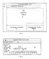
- Fig. 3 illustrates the Main Menu display screen of the interactive terminal shown in Fig. 1.
- Fig. 4 illustrates the display screen presented in response to the user selecting the Calendar function on the Main Menu screen of Fig. 3.
- Fig. 5 illustrates the data structure for storing the calendaring information in the system.
- Fig. 6 illustrates the positioning on the display screen of the main viewport for displaying application data and the Compressed Day Calendar (CDC) viewport for displaying the compressed day calendar data.
- Fig. 7 illustrates the details of the Compressed Day Calendar format that is displayed in the CDC viewport shown in Fig. 6. Description of the Preferred Embodiment:
- Fig. 1 illustrates the functional components of an interactive type data processing terminal on which the electronic calendaring method of the present invention may be advantageously employed. The terminal comprises a
processing unit 11 which includes amicroprocessor block 12, asemiconductor memory 13, and acontrol block 14 which functions to control input/output operations in addition to the interaction between themicro processor block 12 and thememory unit 13. - The terminal further includes a group of conventional peripheral units including a
display device 16, akeyboard 17, aprinter 18, a disk storage unit 19, and amodem 20. Since the details of the above-described functional blocks form no part of the present invention and can be found in the prior art, only a brief functional description of each block is set forth, along with a description of their interactions, sufficient to provide a person of ordinary skill in the art with a basis of understanding applicants' improved method for displaying electronic calendar data. - Processing
unit 11 corresponds to the "system unit" of a personal computer system such as the IBM XT personal computer, IBM AT personal computer or PS/2 personal computer.Unit 11 is provided with an operating system program which may be one of the many versions of DOS (Disk Operating System) which is normally employed to run the systems. The operating system program is stored inmemory 13 along with one or more application programs that the user has selected to run. Depending on the capacity ofmemory 13 and the size of the application programs, portions of these programs, as needed, may be transferred tomemory 13 from the disk storage unit 19 which may include, for example, a 30 megabyte hard disk drive and a diskette drive. The basic function of the disk storage unit is to store programs and data that are employed by the system and which may readily be transferred to thememory unit 13 when needed. The function of the diskette drive is to provide a removable storage function for entering programs and data into the system, and a vehicle for storing data in a form that is readily transportable for use on other terminals or systems. -
Display device 16 andkeyboard 17 together provide for the interactive nature of the terminal, in that in normal operation, the interpretation that the system gives to a specific keystroke by the operator depends, in substantially all situations, on what is being displayed to the operator at that point in time. - In some situations, the operator, by entering commands into the system, causes the system to perform a certain function. In other situations, the system requests the entry of certain data, generally by displaying a prompt type of menu/message screen. The depth of the interaction between the operator and the system varies by the type of operating system and the application program, but is a necessary characteristic of terminals on which the method of the present invention may be employed.
- The terminal shown in Fig. 1 further includes a
printer 18, which functions to provide hard copy output of data developed or stored in the terminal. Themodem 20 functions to transfer data from the terminal of Fig. 1 to a host system through one or more communication links which may be a commercial type link or a dedicated communication link as shown schematically in Fig. 2. Lastly, a mouse 21 is provided to select items that are displayed by moving a selecting cursor that is displayed on the screen and is positional by the mouse. - Fig. 2 represents schematically a network of terminals of the type shown in Fig. 1 which have the ability to communicate with each other through the network. These networks generally include a Host processing system for storing data that is available to all terminals and is responsible for controlling and managing the network.
- Fig. 3 is representative of the display panel that is presented to the user/operator immediately after the terminal is initialized. The content of this display screen is merely an example of the type of options that might be presented to the terminal user, and the overall functional areas of the screen which remain constant and are considered part of the user interface of the system.
- It is assumed that the personal computer is provided with a display management system which uses a command or action bar for the selection of actions and a vertical scroll bar function which allows selected display screens to be scrollable under the control of a mouse.
- The action bar portion of the screen shown in Fig. 3 is designated by referenced
character 31. The commands that are shown for the panel are merely representative. The specific commands that are displayed on the action bar will vary depending on the information being displayed and the point in the task that is being performed. - The user interface screen may also include a
function key area 32 which allows the operator to request predetermined tasks or actions. Generally the task assigned to a function key does not vary within a given application program or operating system. Some function keys have obtained a defacto standard such as function key F1 which is generally used to request the display of a "help" panel. A message area designated 33 may also be provided to display prompts or error messages from the system to the operator. - The
top line 34 of the screen is used to designate the name of the application program and/or the screen name. In a multitasking system, an area may also be provided to indicate other tasks that are presently active which have been open and are executing in a background mode. - The Main Menu screen shown in Fig. 3 includes a number of application tasks which are selectable. Moving the cursor vertically to each line causes the task to be highlighted. Pressing the enter key, causes the highlighted task to be selected. Other selection techniques described in the prior art may also be employed.
- In order to more readily understand the method of displaying day calendar data in a compressed format in accordance with the present invention, a brief description of one method of calendaring events in an electronic calendaring application will first be described. The electronic calendaring arrangement to be described corresponds generally to the arrangement described in application Serial No. 89480014.3. It is assumed for purposes of this description that the operator has just initialized the system and that the "Calendar"
option 35 is selected. The screen shown in Fig. 4 is then displayed. - The screen shown in Fig. 4 comprises a pair of separate but functionally interrelated viewports or
windows 38 and 39. It this respect it should be understood that the terminal is also provided with a state of the art program for establishing and maintaining a number of separate windows or viewports as determined by the user and the various application programs that are to be run. Viewports 38 and 39 are established in accordance with this "windowing" program. -
Viewpoint 38 displays a time structured format in which each display line represents a fixed time period. The displayed format is developed independently of the windowing program. The area or space between a pair of horizontally adjacent lines is allocated to one time slot. As shown, each line or space between adjacent horizontal line represents a 30 minute time period or time slot. The height of theviewport 38 as shown, allows 16 time slots. The view-port therefore covers an eight hour period. Time slots prior to 8:00 a.m. and after 3:30 p.m. may be provided if desired, in which case the information is scrollable to bring these time slots into view. In the preferred embodiment avertical scroll bar 40, including a "thumb", "elevator" or "scroll box" 41, is provided at the right edge of the viewport to permit a scrolling operation employing mouse 21, which first selects the "thumb" with a mouse directed cursor and then drags the "thumb" up or down in a vertical direction by moving the mouse. This operation causes the time slots to scroll either up or down. - The
third area 45 of the viewport is called the busy bar area. Its function is to map busy or committed time slots with a vertical busy bar which extends between the pair of horizontal lines that define the time slot. In practice, two separatebusy bar columns -
Viewport 38 is also provided with its own cursor (not shown) such as a reversed video box. The width of theviewport 38 is approximately 15 display columns as shown . - The second viewport 39 is called the descriptive area and includes a
Start time column 47, anEnd time column 48, and adescriptive area 49. The function of area 39 is to display information in detail about a scheduled event. The Start time of the event is entered inarea 47 while the End time of the event is entered inarea 48 and the text describing the event in thearea 49.Area 49 does not, in theory, limit the amount of text that can be entered although in practice some practical maximum restraint, like 15 lines, may be imposed. It is important to note, that the number of text lines consumed by the description, are independent of the number of lines allocated to the time period scheduled for the event. For example, a description of an event scheduled for one hour, may take ten lines and a description for an event scheduled for an eight hour period may take one line. - The busy bars shown in the time structured
format area 38 of Fig. 4 are directly related to the start and end times of the events that are entered in the descriptive area. For example, when the 10:00 am to 12:00 n event shown in Fig. 4 was entered into the system, the busy bar incolumn 42 was displayed. When the 11:00 am to 12:30 pm entry was entered, a bar was displayed in thesecond column 43 since there was a bar already in the first column. The fact that the entry was made in the second column and not the first, signifies that a scheduling conflict has occurred. The user can readily see the conflict since the bars incolumns - As shown in the drawing, a busy bar for a half-hour time slot begins at an imaginary horizontal line midway between the relevant displayed time and the immediately preceding displayed time. The bar ends at a similar horizontal line underneath the relevant displayed time.
- As explained in the application Serial No. 89480014.3 selection of a time slot for either an initial calendar entry or an editing action on the description of an event that was previously calendared, results in automatic scrolling of the information in the descriptive area to position the appropriate line at some predetermined location on the screen. For example, that predetermined location may be the top line of the screen or a line immediately adjacent the time slot. Positioning a highlighting cursor on the 2:00 pm time slot and pressing the enter key, causes the information area to be scrolled and to place the 2:00 pm entry at the top of the descriptive area.
- Fig. 5 represents one form of data structure for storing the information that has been entered into the system for the calendared events. This data structure is employed to build the screen shown in Fig. 4 and is involved in building the compressed format in accordance with the present invention. The specific details of time structured format shown in the
viewpoint 38 is selected by the user. While the user's default selection as established in his profile will generally be employed at the time the system is IPLed, the selection may be modified at any time by appropriate action of the user in that the length of the work day can be increased and the time span or period of time slot can be shortened or lengthened. - The busy time bars are mapped dynamically by a program that scans the data stored in the data structure shown in Fig. 5. A map similar to that shown in Table 1, below, is used to build the busy bar area of the screen of Fig. 4.
- The rows of the map shown in Table 1 correspond to time slots that have been allocated in the time structured format of
viewport 38. The columns designated 0 and 1, correspond to the two columns of busy bars shown in Fig. 4. As shown in Table 1, a third column may also be mapped if desired, since acolumn 2 is provided in the map.
- The following pseudocode statements will be of interest to programmers in developing a program to create the busy bars.

- An example of a busy bar position map for the screen of Fig. 4 is shown in Table 1. A 1 in column 0, at rows 2 - 7, and 12-13, and in
column 1, rows 6 - 8 generates the busy bars shown in Fig. 4. This map is developed in accordance with the pseudo code listing set forth above and is used to build the busy bar section of the display that appears inviewport 38. - Fig. 6 illustrates the general layout of the screen that is presented to the terminal user with the method of the present invention. Fig. 6 for example would be presented to the user after he has selected an option from the Main Menu involving an application program such as the "Spreadsheet" option or the "Wordprocessor" option. In accordance with the method of the present invention, the screen is divided into at least a Main Application viewport and a Compressed Daily Calendar viewport. As shown in Fig. 6 the
Main Application viewport 70 occupies a substantial portion of the screen while theCDC viewport 71 occupies the lower right hand corner of the screen. An IconParking Lot viewport 72 occupies the lower left hand corner of the screen. The dimensions of the respective viewports are variable in accordance with data provided to the windowing application program. In practice the size of the main application viewport is chosen to meet the users requirements for that application. - If, for example, the technology employed by the display provides a screen of 25 display lines and 80 columns the
main application viewport 70 would be 20 by 80 while theCDC viewport 71 and IconParking Lot viewport 72 would each have a viewable area of 5 by 40. The actual size of the CDC viewport as shown is 7 by 40 with the top 2 lines being covered bybottom 2 lines of theviewport 70. The top twolines viewport 71 and an action bar for selecting actions involving the information contained in this viewport. As in most windowing applications the covered portion ofviewport 71 containinglines viewport 70 with the mouse selecting cursor and dragging the an edge toward the top of the screen. - The CDC compressed format shown in Fig. 7 comprises a
time slot line 85, which is appropriately labeled with times that correspond to the day calendar of the user and in which the time slot period also matches the time slot period of the user's day calendar. The format further includes a "Busy Bar"line 86 which functions to indicate those time slots which involve calendared events. A "Busy Bar" is positioned immediately above the time slot if it contains a calendared event. As shown the "Busy Bar" 87 extends from 9:00 am to 12:00 n which corresponds to the events shown in Fig.4 and Fig. 5. The format further includes aConflict line 88 which functions to indicate when more than one event has been scheduled for the particular. As shown if Fig. 7 the fact that the user has a schedule conflict for the two time slot periods of 11:00 am to 12:00 n is indicated by "Busy Bar" 89. A second conflict line may also be provided in the format if desired. - The "Busy Bars" are developed for the CDC viewport in the same manner as described in connection with the
viewport 38 of Fig. 4 - As shown in Fig. 7 the format also provides the user with a "Time-of-Day"
indicator 90 which moves alongtime line 85 under the control of the systems clock. This indicator would be a different color on a color monitor or be highlighted on a monochrome monitor. - The format further provides for the user to change from the current day to either a future day or a previous day. As shown in Fig. 7 the format includes a "Next"
button 93 and "Prev"(ious)button 94. By positioning the selecting cursor of the mouse on one of these buttons and "clicking" the mouse the CDC viewport is updated with the next/previous day's calendar data. The date in the title line at the top of the viewport is also changed. - In a calendaring application involving a network of terminals as shown in Fig. 2 in which user are allowed to calendar events on each others calendar, the method of the present invention provides an indication in the CDC viewport that an event has been calendared since the time that the user last viewed his daily calendar. Two situations occur which in the preferred embodiment are treated somewhat differently.
- The first situation addresses the scenario where the user is currently on line and another user has just calendared an event for later on in the day. In that situation A "Busy Bar" is displayed on
line - The second situation involves the scenario where the newly calendared event is on some future day. In this situation the
indicator 95 labeled "Chg" in the upper right hand corner ofviewport 71 as shown in Fig. 7 is turned on. In the preferred embodiment, when this indicator is turned on, it means that the user's calendar includes events that have been calendared since the time that the Compressed Day Calendar screen was displayed. By cursoring to this indicator and clicking the mouse, the user is presented with a list of newly calendared events and any calendared events that have been changed, for his review and further action. If desired, the on condition of the "Change" indicator could signify that a new event was calendared or an event changed, since either the end of the last terminal session or the beginning of the terminal session. This would require an assumption that the system would keep track of the last time that the user viewed the main calendar screens. - All of the above described activity on the part of the user need not be taken until it is convenient for the user to do so. The schedule and calendar information is presented to the user on a continuous basis along with the data that is being processed by an entirely separate application program. The user never has to exit from the application program to check his day calendar merely to understand what time is free or what time is busy.
Claims (14)
displaying in said first viewport a busy indication for each said time period that has been calendared with an event.
Applications Claiming Priority (2)
| Application Number | Priority Date | Filing Date | Title |
|---|---|---|---|
| US18892788A | 1988-05-02 | 1988-05-02 | |
| US188927 | 1988-05-02 |
Publications (3)
| Publication Number | Publication Date |
|---|---|
| EP0342140A2 true EP0342140A2 (en) | 1989-11-15 |
| EP0342140A3 EP0342140A3 (en) | 1991-08-07 |
| EP0342140B1 EP0342140B1 (en) | 1996-01-24 |
Family
ID=22695148
Family Applications (1)
| Application Number | Title | Priority Date | Filing Date |
|---|---|---|---|
| EP19890480031 Expired - Lifetime EP0342140B1 (en) | 1988-05-02 | 1989-02-28 | Method for presenting compressed electronic day calendar information in an interactive information handling system |
Country Status (5)
| Country | Link |
|---|---|
| EP (1) | EP0342140B1 (en) |
| JP (1) | JPH01292287A (en) |
| BR (1) | BR8902040A (en) |
| CA (1) | CA1313416C (en) |
| DE (1) | DE68925496D1 (en) |
Cited By (7)
| Publication number | Priority date | Publication date | Assignee | Title |
|---|---|---|---|---|
| WO1993012490A1 (en) * | 1991-12-12 | 1993-06-24 | International Business Machines Corporation | Method of and apparatus for providing direct automatic access of a calendar task from a non-calendar task |
| EP0740255A1 (en) * | 1995-04-25 | 1996-10-30 | Sharp Kabushiki Kaisha | Electronic scheduler |
| US7257778B2 (en) | 2002-05-31 | 2007-08-14 | Nokia Corporation | Calendar system and a method for producing a calendar view |
| WO2008025117A1 (en) * | 2006-08-31 | 2008-03-06 | Research In Motion Limited | Agenda determination in an electronic device |
| US7849102B2 (en) | 2005-09-07 | 2010-12-07 | Microsoft Corporation | Availability data service |
| US7930651B2 (en) | 2007-01-18 | 2011-04-19 | Research In Motion Limited | Agenda display in an electronic device |
| EP2016484A4 (en) * | 2006-05-05 | 2015-11-18 | Microsoft Technology Licensing Llc | Agenda and day hybrid calendar view |
Families Citing this family (3)
| Publication number | Priority date | Publication date | Assignee | Title |
|---|---|---|---|---|
| JP2680736B2 (en) * | 1990-10-18 | 1997-11-19 | シャープ株式会社 | Electronic device having schedule management function |
| EP2062208A4 (en) * | 2006-08-31 | 2011-04-06 | Research In Motion Ltd | Conflict checking and notification in an electronic device |
| US8146014B2 (en) | 2006-08-31 | 2012-03-27 | Research In Motion Limited | Controlling a message display in an electronic device |
Citations (2)
| Publication number | Priority date | Publication date | Assignee | Title |
|---|---|---|---|---|
| DE3520894A1 (en) * | 1984-06-11 | 1985-12-12 | Sharp Kk | ELECTRONIC NOTICE PROCEDURE |
| US4591840A (en) * | 1983-11-04 | 1986-05-27 | International Business Machines Corp. | Calendar event description abbreviation |
Family Cites Families (2)
| Publication number | Priority date | Publication date | Assignee | Title |
|---|---|---|---|---|
| JPS61139869A (en) * | 1984-12-12 | 1986-06-27 | Nec Corp | Deletion system for schedule input |
| JPS6247771A (en) * | 1985-08-27 | 1987-03-02 | Nec Corp | Schedule inputting/editing method |
-
1989
- 1989-01-25 CA CA000589123A patent/CA1313416C/en not_active Expired - Fee Related
- 1989-02-20 JP JP1038540A patent/JPH01292287A/en active Pending
- 1989-02-28 DE DE68925496T patent/DE68925496D1/en not_active Expired - Lifetime
- 1989-02-28 EP EP19890480031 patent/EP0342140B1/en not_active Expired - Lifetime
- 1989-04-28 BR BR898902040A patent/BR8902040A/en unknown
Patent Citations (2)
| Publication number | Priority date | Publication date | Assignee | Title |
|---|---|---|---|---|
| US4591840A (en) * | 1983-11-04 | 1986-05-27 | International Business Machines Corp. | Calendar event description abbreviation |
| DE3520894A1 (en) * | 1984-06-11 | 1985-12-12 | Sharp Kk | ELECTRONIC NOTICE PROCEDURE |
Non-Patent Citations (1)
| Title |
|---|
| RESEARCH DISCLOSURE, no. 276, April 1987, page 204, disclosure no. 27632; "Surrogate calendar keeper (calendar server)" * |
Cited By (8)
| Publication number | Priority date | Publication date | Assignee | Title |
|---|---|---|---|---|
| WO1993012490A1 (en) * | 1991-12-12 | 1993-06-24 | International Business Machines Corporation | Method of and apparatus for providing direct automatic access of a calendar task from a non-calendar task |
| EP0740255A1 (en) * | 1995-04-25 | 1996-10-30 | Sharp Kabushiki Kaisha | Electronic scheduler |
| US5689687A (en) * | 1995-04-25 | 1997-11-18 | Sharp Kabushiki Kaisha | Electronic device |
| US7257778B2 (en) | 2002-05-31 | 2007-08-14 | Nokia Corporation | Calendar system and a method for producing a calendar view |
| US7849102B2 (en) | 2005-09-07 | 2010-12-07 | Microsoft Corporation | Availability data service |
| EP2016484A4 (en) * | 2006-05-05 | 2015-11-18 | Microsoft Technology Licensing Llc | Agenda and day hybrid calendar view |
| WO2008025117A1 (en) * | 2006-08-31 | 2008-03-06 | Research In Motion Limited | Agenda determination in an electronic device |
| US7930651B2 (en) | 2007-01-18 | 2011-04-19 | Research In Motion Limited | Agenda display in an electronic device |
Also Published As
| Publication number | Publication date |
|---|---|
| CA1313416C (en) | 1993-02-02 |
| EP0342140A3 (en) | 1991-08-07 |
| DE68925496D1 (en) | 1996-03-07 |
| EP0342140B1 (en) | 1996-01-24 |
| BR8902040A (en) | 1989-12-05 |
| JPH01292287A (en) | 1989-11-24 |
Similar Documents
| Publication | Publication Date | Title |
|---|---|---|
| US5129057A (en) | Method for presenting compressed electronic day calendar information in an interactive information handling system | |
| US5023851A (en) | Method for presenting electronic calendar information in an interactive information handling system | |
| EP0326778B1 (en) | Method to facilitate a reply to electronic meeting invitation in an interactive multi-terminal system employing electronic calendars | |
| Myers | A taxonomy of window manager user interfaces | |
| US6049334A (en) | Method and system for graphically indicating the activity of a plurality of users within a shared data collection | |
| US5247438A (en) | Personal time management system and method | |
| US5570109A (en) | Schedule and to-do list for a pen-based computer system | |
| US5659768A (en) | System and method for the time representation of tasks | |
| US5577188A (en) | Method to provide for virtual screen overlay | |
| US6466236B1 (en) | System and method for displaying and manipulating multiple calendars on a personal digital assistant | |
| KR950014983B1 (en) | Method and apparatus for distinctively displaying window on a computer display screen | |
| US6236396B1 (en) | Method and apparatus for controlling a scheduler | |
| CA2040342C (en) | Computer user interface with window title bar icons | |
| US9501213B2 (en) | Scheduling events on an electronic calendar utilizing fixed-positioned events and a draggable calendar grid | |
| US5050105A (en) | Direct cursor-controlled access to multiple application programs and data | |
| US5625377A (en) | Method for controlling a computerized organizer | |
| US4881179A (en) | Method for providing information security protocols to an electronic calendar | |
| US5867678A (en) | Method and system for searching and retrieving specific types of objects contained within a compound document | |
| US5936623A (en) | Method and apparatus for selecting a particular object from among a large number of objects | |
| US6892346B1 (en) | Collapsing event display for small screen computer | |
| US6040833A (en) | Method and system for display manipulation of multiple applications in a data processing system | |
| EP1278116A1 (en) | Operator interface | |
| US20130205254A1 (en) | System and Method for Assigning and Scheduling Activities | |
| EP0342140B1 (en) | Method for presenting compressed electronic day calendar information in an interactive information handling system | |
| EP0344082B1 (en) | Method for accessing visually obscured data in a multi-tasking system |
Legal Events
| Date | Code | Title | Description |
|---|---|---|---|
| PUAI | Public reference made under article 153(3) epc to a published international application that has entered the european phase |
Free format text: ORIGINAL CODE: 0009012 |
|
| AK | Designated contracting states |
Kind code of ref document: A2 Designated state(s): DE FR GB IT |
|
| 17P | Request for examination filed |
Effective date: 19900326 |
|
| PUAL | Search report despatched |
Free format text: ORIGINAL CODE: 0009013 |
|
| AK | Designated contracting states |
Kind code of ref document: A3 Designated state(s): DE FR GB IT |
|
| 17Q | First examination report despatched |
Effective date: 19940120 |
|
| GRAA | (expected) grant |
Free format text: ORIGINAL CODE: 0009210 |
|
| AK | Designated contracting states |
Kind code of ref document: B1 Designated state(s): DE FR GB IT |
|
| PG25 | Lapsed in a contracting state [announced via postgrant information from national office to epo] |
Ref country code: FR Effective date: 19960124 Ref country code: IT Free format text: LAPSE BECAUSE OF FAILURE TO SUBMIT A TRANSLATION OF THE DESCRIPTION OR TO PAY THE FEE WITHIN THE PRESCRIBED TIME-LIMIT;WARNING: LAPSES OF ITALIAN PATENTS WITH EFFECTIVE DATE BEFORE 2007 MAY HAVE OCCURRED AT ANY TIME BEFORE 2007. THE CORRECT EFFECTIVE DATE MAY BE DIFFERENT FROM THE ONE RECORDED. Effective date: 19960124 |
|
| REF | Corresponds to: |
Ref document number: 68925496 Country of ref document: DE Date of ref document: 19960307 |
|
| PG25 | Lapsed in a contracting state [announced via postgrant information from national office to epo] |
Ref country code: GB Effective date: 19960424 |
|
| PG25 | Lapsed in a contracting state [announced via postgrant information from national office to epo] |
Ref country code: DE Effective date: 19960425 |
|
| EN | Fr: translation not filed | ||
| PLBE | No opposition filed within time limit |
Free format text: ORIGINAL CODE: 0009261 |
|
| STAA | Information on the status of an ep patent application or granted ep patent |
Free format text: STATUS: NO OPPOSITION FILED WITHIN TIME LIMIT |
|
| GBPC | Gb: european patent ceased through non-payment of renewal fee |
Effective date: 19960424 |
|
| 26N | No opposition filed |