EP0334701A1 - Removable system for the fixation of a sun shade on a spectacle frame - Google Patents
Removable system for the fixation of a sun shade on a spectacle frame Download PDFInfo
- Publication number
- EP0334701A1 EP0334701A1 EP89400598A EP89400598A EP0334701A1 EP 0334701 A1 EP0334701 A1 EP 0334701A1 EP 89400598 A EP89400598 A EP 89400598A EP 89400598 A EP89400598 A EP 89400598A EP 0334701 A1 EP0334701 A1 EP 0334701A1
- Authority
- EP
- European Patent Office
- Prior art keywords
- frame
- solar face
- solar
- elements
- face
- Prior art date
- Legal status (The legal status is an assumption and is not a legal conclusion. Google has not performed a legal analysis and makes no representation as to the accuracy of the status listed.)
- Withdrawn
Links
Images

Classifications
-
- G—PHYSICS
- G02—OPTICS
- G02C—SPECTACLES; SUNGLASSES OR GOGGLES INSOFAR AS THEY HAVE THE SAME FEATURES AS SPECTACLES; CONTACT LENSES
- G02C9/00—Attaching auxiliary optical parts
-
- G—PHYSICS
- G02—OPTICS
- G02C—SPECTACLES; SUNGLASSES OR GOGGLES INSOFAR AS THEY HAVE THE SAME FEATURES AS SPECTACLES; CONTACT LENSES
- G02C7/00—Optical parts
- G02C7/10—Filters, e.g. for facilitating adaptation of the eyes to the dark; Sunglasses
Definitions
- the present invention relates to a removable system for fixing a solar face to a spectacle frame.
- sun protection to protect your eyes, especially from the sun's rays.
- This protection materialized by a tinted solar face is either directly fixed to a frame to form sunglasses, or attached to the optical lenses of a pair of vision correction glasses.
- sunscreen it is necessary to understand as well a single tinted glass called sunscreen, as two tinted glasses linked together by a metal frame.
- Each fixing system comprises at least one lug fixed to the solar face and which comes into contact with one face of the associated optical glass, and at least one lug which, either by elastic deformation of the solar face, or by its own elasticity, comes into contact with the other side of the associated optical glass.
- clamping or clamping fastening systems have the drawback of causing scratching of the optical glasses, all the more so since the clamps are metallic.
- these fixing systems are such that, once mounted on the upper part of the optical glasses, the lower part of the solar face is found in contact with the lower wall. corresponding optical glasses. Such contact also entails a non-negligible risk of scratching the optical glasses by friction, as a result of repeated operations of assembly and disassembly of the solar face.
- the object of the invention is to design a fixing system which eliminates the aforementioned drawbacks, while providing other advantages.
- the invention provides a removable system for fixing a solar face to a spectacle frame, which is characterized in that it comprises two fasteners each constituted by two assembly elements respectively carried by the frame and by the solar face, said elements being nestable one inside the other after elastic deformation of the solar face.
- the two assembly elements of a fastener are constituted by two male and female elements respectively mounted by sliding one inside the other, the elastic restoring force exerted by the solar face being sufficient to hold it in place on the mount.
- the rigidity of the material constituting the frame must be greater than the rigidity of the material constituting the solar face.
- each assembly element associated with the solar face is carried by a support block, advantageously made of plastic material, which is fixed, for example removably, to the solar face, this element d assembly being of male or female type according to the configuration adopted.
- the male and female assembly elements of a fastener are preferably made of plastic.
- the fixing system according to the invention makes it possible to produce sunglasses with a removable solar face, which has the advantage of changing the solar face at will and easily replacing a defective solar face.
- the fixing system according to the invention also makes it possible to attach a solar face to optical glasses without risk of scratching the glasses, given, on the one hand, that the fixing system has no direct contact with the glasses and , on the other hand, that the support blocks of the solar face are assembled to the frame in such a way that the solar face is always kept away from optical glasses.
- FIG. 1 is a perspective view showing the assembly of a solar face on a spectacle frame according to a first embodiment applied to sunglasses
- FIG. 2 is a schematic top view of the principle of elastic deformation of the solar face necessary for the assembly shown in FIG. 1
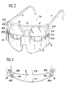
- - Figures 3 and 4 are views similar to Figures 1 and 2 according to a second embodiment of the invention applied to optical glasses.
- the sunglasses 1a shown in FIG. 1 include a frame 2 and a sun face 3 assembled to each other by a fixing system according to the invention.
- the frame 2 is formed by a thin strip, slightly curved along a small radius of curvature.
- Two branches 4 are mounted articulated at the two ends of the mount 2, in a manner known per se, by means of screws 5 for example.
- the solar face 3 is here a one-piece sunscreen tinted in plastic and curved according to a radius of curvature R1.
- the system for fixing the sun screen 3 to the frame 2 comprises two fasteners of identical structure.
- Each fastener is formed of a so-called male element 6a and of a so-called female element 6b which fit together.
- the male element 6a is carried by the frame 2 and the female element 6b is carried by the sun screen 3.
- the male element 6a is in the form of a rod which, advantageously, can be constituted by the extension of the connecting screw 5 between frame 2 and branch 4, and the female element 6b is constituted by a hole provided in a support block 8 made of plastic.
- the sun screen 3 supports two support blocks 8 mounted on the two substantially rectilinear side edges of the screen 3.
- each support block 8 has at least one flat face with a groove 8a in which a force engages a side edge of screen 3 for example.
- the sun screen 3 and the two support blocks 8 thus assembled form a sub-assembly which, as illustrated in strong lines in FIG. 2, is such that the distance x separating the two holes 6b from the two support blocks 8 before mounting is less than the distance y separating the two associated rods 6a.
- the fixing system according to the invention is applied, according to the same principle, to a pair of optical glasses 1b equipped with corrective lenses 9 on which we have just reported a sunscreen 3 similar to the sunscreen previously described. Also, the same reference figures have been kept for the elements common to these two embodiments.
- each support block 8 comprises a second groove 8b substantially parallel to the groove 8b and located on the same face of the support block 8.
- This groove 8b constitutes the female assembly element of each attachment of the fixing system.
- the male element is constituted by an external edge 6a of the mount 2, substantially rectilinear and extending in a plane parallel to the groove 8b.
- the distance separating the two grooves 8b is less, before mounting, than the distance separating the two edges 6a of the frame 2, and by elastic deformation of the screen solar 3, these two distances are made substantially equal to allow assembly as shown in FIG. 3.
- each support block comprised between the two grooves 8a, 8b constitutes a spacer 8c which makes it possible to keep the sun screen 3 away from the corrective lenses 9 in order to avoid any contact between them.
- the space between corrective lenses 9 of the screen 3 is determined by the thickness of the spacer 8c.
- the principle of mounting the sun screen 3 assumes that the rigidity of the frame 2 is greater than that of the sun screen 3.
- the male element 6a can be a hollow or pierced rod, fixed towards one end of the support block 8, and internally threaded towards its other end at the pitch of the screw. assembly 5 between branch and frame.
- the screw 5, longer than the width of the branches 4, is then screwed into the rod which, in addition, serves as a lock nut to prevent loosening of the screw.
- the mounts 2 may or may not be metallic, the male elements 6a, and the support blocks 8 advantageously being made of plastic.
- each support block 8 can be screwed onto the sun screen 3, in particular if it is not made of the same material as the screen, or else each support block 8 with its groove 8b or its hole 6b can be made of the same material as the sunscreen 3 to form an assembly directly from molding.
- each support block 8 can be fixed by gluing to the screen 3.
- the male 6a and female 6b, 8b elements without changing the principle of the invention can be reversed, that is to say that the male element 6a can be supported by the sun screen 3 and that the female element 6b , 8b can be supported by mount 2.
- fixing system with groove 8b and edge (6a) as described according to the second embodiment can also be applied to the first embodiment.
- the invention is in no way limited to the embodiments which have been described only by way of example.
- the solar face constituted by a monobloc screen can also be replaced by a solar face constituted by two glasses connected by a flexible metal frame.
Abstract
Description
La présente invention concerne un système amovible de fixation d'une face solaire sur une monture de lunettes.The present invention relates to a removable system for fixing a solar face to a spectacle frame.
D'une manière générale, il est courant de recourir à une protection solaire pour protéger ses yeux, notamment des rayons du soleil. Cette protection matérialisée par une face solaire teintée est soit directement fixée sur une monture pour former des lunettes de soleil, soit rapportée sur les verres optiques d'une paire de lunettes de correction de la vue. Par face solaire, il faut entendre aussi bien un seul verre teinté dénommé écran solaire, que deux verres teintés reliés entre eux par une armature métallique.Generally, it is common to use sun protection to protect your eyes, especially from the sun's rays. This protection materialized by a tinted solar face is either directly fixed to a frame to form sunglasses, or attached to the optical lenses of a pair of vision correction glasses. By solar face, it is necessary to understand as well a single tinted glass called sunscreen, as two tinted glasses linked together by a metal frame.
Pour rapporter une face solaire sur des verres optiques, on utilise généralement deux systèmes de fixation à pinces ou formant pinces qui viennent en prise sur les deux verres optiques, respectivement. Chaque système de fixation comprend au moins une patte fixée à la face solaire et qui vient au contact d'une face du verre optique associé, et au moins une patte qui, soit par déformation élastique de la face solaire, soit par sa propre élasticité, vient au contact de l'autre face du verre optique associé.To attach a solar face to optical glasses, two clamping systems or clamping systems are generally used which engage on the two optical glasses, respectively. Each fixing system comprises at least one lug fixed to the solar face and which comes into contact with one face of the associated optical glass, and at least one lug which, either by elastic deformation of the solar face, or by its own elasticity, comes into contact with the other side of the associated optical glass.
Ces systèmes de fixation à pinces ou formant pinces présentent l'inconvénient d'entraîner le rayage des verres optiques et ce, d'autant plus, que les pinces sont métalliques. En outre, ces systèmes de fixation sont tels, qu'une fois montés à la partie supérieure des verres optiques, la partie inférieure de la face solaire se retrouve au contact de la paroi inférieure correspondante des verres optiques. Un tel contact entraîne également un risque non négligeable de rayage des verres optiques par frottement, par suite des opérations répétées d'assemblage et de désassemblage de la face solaire.These clamping or clamping fastening systems have the drawback of causing scratching of the optical glasses, all the more so since the clamps are metallic. In addition, these fixing systems are such that, once mounted on the upper part of the optical glasses, the lower part of the solar face is found in contact with the lower wall. corresponding optical glasses. Such contact also entails a non-negligible risk of scratching the optical glasses by friction, as a result of repeated operations of assembly and disassembly of the solar face.
Le but de l'invention est de concevoir un système de fixation qui supprime les inconvénients précités, tout en procurant d'autres avantages.The object of the invention is to design a fixing system which eliminates the aforementioned drawbacks, while providing other advantages.
A cet effet, l'invention propose un système amovible de fixation d'une face solaire sur une monture de lunettes , qui se caractérise en ce qu'il comprend deux attaches constituées chacune par deux éléments d'assemblage respectivement portés par la monture et par la face solaire, lesdits éléments étant emboîtables l'un dans l'autre après déformation élastique de la face solaire.To this end, the invention provides a removable system for fixing a solar face to a spectacle frame, which is characterized in that it comprises two fasteners each constituted by two assembly elements respectively carried by the frame and by the solar face, said elements being nestable one inside the other after elastic deformation of the solar face.
Selon une autre disposition de l'invention, les deux éléments d'assemblage d'une attache sont constitués par deux éléments respectivement mâle et femelle montés par glissement l'un dans l'autre, la force de rappel élastique exercée par la face solaire étant suffisante pour maintenir celle-ci en place sur la monture.According to another arrangement of the invention, the two assembly elements of a fastener are constituted by two male and female elements respectively mounted by sliding one inside the other, the elastic restoring force exerted by the solar face being sufficient to hold it in place on the mount.
Selon une autre disposition de l'invention, la rigidité du matériau constituant la monture doit être supérieure à la rigidité du matériau constituant la face solaire.According to another arrangement of the invention, the rigidity of the material constituting the frame must be greater than the rigidity of the material constituting the solar face.
Selon une autre disposition de l'invention, chaque élément d'assemblage associé à la face solaire est porté par un bloc de support, avantageusement en matériau plastique, qui est fixé, par exemple de manière amovible, à la face solaire, cet élément d'assemblage étant de type mâle ou femelle suivant la configuration adoptée.According to another arrangement of the invention, each assembly element associated with the solar face is carried by a support block, advantageously made of plastic material, which is fixed, for example removably, to the solar face, this element d assembly being of male or female type according to the configuration adopted.
Selon une autre disposition de l'invention, les éléments d'assemblage mâle et femelle d'une attache sont de préférence en matière plastique.According to another arrangement of the invention, the male and female assembly elements of a fastener are preferably made of plastic.
Grâce à ces différentes dispositions, le système de fixation conforme à l'invention permet de réaliser des lunettes solaires à face solaire amovible, ce qui présente l'avantage de changer à volonté la face solaire et de remplacer facilement une face solaire défectueuse.Thanks to these various arrangements, the fixing system according to the invention makes it possible to produce sunglasses with a removable solar face, which has the advantage of changing the solar face at will and easily replacing a defective solar face.
Le système de fixation conforme à l'invention permet également de rapporter une face solaire sur des verres optiques sans risque de rayage des verres, étant donné, d'une part, que le système de fixation n'a aucun contact direct avec les verres et, d'autre part, que les blocs de support de la face solaire sont assemblés à la monture d'une manière telle que la face solaire est toujours maintenue éloignée des verres optiques.The fixing system according to the invention also makes it possible to attach a solar face to optical glasses without risk of scratching the glasses, given, on the one hand, that the fixing system has no direct contact with the glasses and , on the other hand, that the support blocks of the solar face are assembled to the frame in such a way that the solar face is always kept away from optical glasses.
D'autres avantages, caractéristiques et détails ressortiront de la description explicative qui va suivre faite en référence aux dessins annexés donnés uniquement à titre d'exemple et dans lesquels:
- la figure 1 est une vue en perspective montrant l'assemblage d'une face solaire sur une monture de lunettes suivant un premier mode de réalisation appliqué à des lunettes de soleil,
- la figure 2 est une vue schématique de dessus du principe de déformation élastique de la face solaire nécessaire pour l'assemblage représenté à la figure 1, et
- les figures 3 et 4 sont des vues analogues aux figures 1 et 2 suivant un second mode de réalisation de l'invention appliqué à des lunettes optiques.Other advantages, characteristics and details will emerge from the explanatory description which follows, given with reference to the appended drawings given solely by way of example and in which:
FIG. 1 is a perspective view showing the assembly of a solar face on a spectacle frame according to a first embodiment applied to sunglasses,
FIG. 2 is a schematic top view of the principle of elastic deformation of the solar face necessary for the assembly shown in FIG. 1, and
- Figures 3 and 4 are views similar to Figures 1 and 2 according to a second embodiment of the invention applied to optical glasses.
Les lunettes de soleil 1a représentées à la figure 1 comprennent une monture 2 et une face solaire 3 assemblées l'une à l'autre par un système de fixation conforme à l'invention.The sunglasses 1a shown in FIG. 1 include a
Dans l'exemple considéré ici, la monture 2 est formée par une barrette de faible épaisseur, légèrement cintrée suivant un faible rayon de courbure. Deux branches 4 sont montées articulées aux deux extrémités de la monture 2, d'une manière connue en soi, au moyen de vis 5 par exemple.In the example considered here, the
La face solaire 3 est ici un écran solaire monobloc teinté en matière plastique et cintré suivant un rayon de courbure R1.The
Le système de fixation de l'écran solaire 3 sur la monture 2 comprend deux attaches de structure identique. Chaque attache est formée d'un élément dit mâle 6a et d'un élément dit femelle 6b emboîtables l'un dans l'autre. Dans l'exemple considéré ici, l'élément mâle 6a est porté par la monture 2 et l'élément femelle 6b est porté par l'écran solaire 3.The system for fixing the
Plus précisément, l'élément mâle 6a se présente sous la forme d'une tige qui, avantageusement, peut être constituée par le prolongement de la vis d'assemblage 5 entre monture 2 et branche 4, et l'élément femelle 6b est constituée par un trou prévu dans un bloc de support 8 en matière plastique.More specifically, the
L'écran solaire 3 supporte deux blocs de support 8 montés sur les deux bords latéraux sensiblement rectilignes de l'écran 3. Pour cela, chaque bloc support 8 possède au moins une face plane avec une rainure 8a dans laquelle s'engage à force un bord latérale de l'écran 3 par exemple.The
L'écran solaire 3 et les deux blocs de support 8 ainsi assemblés forment un sous-ensemble qui, comme illustré en traits forts à la figure 2, est tel que la distance x séparant les deux trous 6b des deux blocs de support 8 avant montage est inférieure à la distance y séparant les deux tiges associées 6a. Pour permettre le montage, il suffit d'exercer une pression sur l'écran solaire 3 de manière à ce que, par déformation élastique de ce dernier, la distance x soit rendue sensiblement égale à la distance y pour que les deux tiges 6a soient sensiblement axialement alignées avec les trous 6b correspondants, comme illustré en traits mixtes à la figure 2. Autrement dit, il faut, par déformation élastique augmenter le rayon de courbure R1 de l'écran solaire 3 jusqu'à une valeur R2 pour rendre sensiblement égales les distances x et y. Ensuite, par emboîtement glissant, les tiges 6a viennent s'engager dans les trous 6b, et l'assemblage est maintenu grâce à la force de rappel élastique exercée par l'écran solaire 3 lui-même.The
En référence aux figures 3 et 4, le système de fixation conforme à l'invention est appliqué, suivant un même principe, a une paire de lunettes optique 1b équipée de verres correcteurs 9 sur lesquels on vient rapporter un écran solaire 3 analogue à l'écran solaire précédemment décrit. Aussi, les mêmes chiffres de référence ont été conservés pour les éléments communs à ces deux modes de réalisation.With reference to FIGS. 3 and 4, the fixing system according to the invention is applied, according to the same principle, to a pair of optical glasses 1b equipped with
Dans le second mode de réalisation considéré ici, chaque bloc de support 8 comprend une deuxième rainure 8b sensiblement parallèle à la rainure 8b et située sur la même face du bloc de support 8. Cette rainure 8b constitue l'élément d'assemblage femelle de chaque attache du système de fixation. L'élément mâle est constitué par une arête externe 6a de la monture 2, sensiblement rectiligne et s'étendant dans un plan parallèle à la rainure 8b. En se reportant à la figure 4 et comme dans le mode de réalisation précédent, la distance séparant les deux rainures 8b est inférieure, avant montage, à la distance séparant les deux arêtes 6a de la monture 2, et par déformation élastique de l'écran solaire 3, ces deux distances sont rendues sensiblement égales pour permettre l'assemblage tel que montré à la figure 3.In the second embodiment considered here, each
Il est à noter que la partie de chaque bloc de support comprise entre les deux rainures 8a, 8b constitue une entretoise 8c qui permet de maintenir l'écran solaire 3 éloigné des verres correcteurs 9 afin d'éviter tout contact entre eux. L'espace séparant les verres correcteurs 9 de l'écran 3 est déterminé par l'épaisseur de l'entretoise 8c.It should be noted that the part of each support block comprised between the two
Dans les deux modes de réalisation, le principe de montage de l'écran solaire 3 suppose que la rigidité de la monture 2 est supérieure à celle de l'écran solaire 3.In both embodiments, the principle of mounting the
En variante du mode de réalisation représenté aux figures 1 et 2, l'élément mâle 6a peut être une tige creuse ou percée, solidaire vers une extrémité du bloc de support 8, et filetée intérieurement vers son autre extrémité au pas de la vis d'assemblage 5 entre branche et monture. La vis 5, plus longue que la largeur des branches 4, vient alors se visser dans la tige qui, en plus, sert de contre-écrou pour empêcher le desserrage de la vis.As a variant of the embodiment shown in FIGS. 1 and 2, the
A titre d'exemple, les montures 2 peuvent être métalliques ou non, les éléments mâles 6a, et les blocs de support 8 étant avantageusement en matière plastique. En variante, chaque bloc de support 8 peut être vissé sur l'écran solaire 3, en particulier si il n'est pas réalisé dans la même matière que l'écran, ou bien chaque bloc de support 8 avec sa rainure 8b ou son trou 6b peut être réalisé dans la même matière que l'écran solaire 3 pour former un ensemble directement issu de moulage. Enfin, chaque bloc de support 8 peut être fixé par collage à l'écran 3.By way of example, the
Les éléments mâle 6a et femelle 6b, 8b sans changer le principe de l'invention peuvent être inversés, c'est-à-dire que l'élément mâle 6a peut être supporté par l'écran solaire 3 et que l'élément femelle 6b, 8b peut être supporté par la monture 2.The male 6a and female 6b, 8b elements without changing the principle of the invention can be reversed, that is to say that the
En outre, le système de fixation avec rainure 8b et arête (6a) tel que décrit selon le second mode de réalisation peut également être appliqué au premier mode de réalisation.In addition, the fixing system with groove 8b and edge (6a) as described according to the second embodiment can also be applied to the first embodiment.
Bien entendu, l'invention n'est nullement limitée aux modes de réalisation qui n'ont été décrits qu'à titre d'exemple. En particulier, la face solaire constituée par un écran monobloc peut également être remplacée par une face solaire constituée par deux verres reliés par une armature métallique flexible.Of course, the invention is in no way limited to the embodiments which have been described only by way of example. In particular, the solar face constituted by a monobloc screen can also be replaced by a solar face constituted by two glasses connected by a flexible metal frame.
Claims (13)
Applications Claiming Priority (2)
| Application Number | Priority Date | Filing Date | Title |
|---|---|---|---|
| FR8803429 | 1988-03-17 | ||
| FR8803429A FR2628852B1 (en) | 1988-03-17 | 1988-03-17 | REMOVABLE SYSTEM FOR FIXING A SOLAR FACE ON A GLASSES MOUNT |
Publications (1)
| Publication Number | Publication Date |
|---|---|
| EP0334701A1 true EP0334701A1 (en) | 1989-09-27 |
Family
ID=9364335
Family Applications (1)
| Application Number | Title | Priority Date | Filing Date |
|---|---|---|---|
| EP89400598A Withdrawn EP0334701A1 (en) | 1988-03-17 | 1989-03-03 | Removable system for the fixation of a sun shade on a spectacle frame |
Country Status (3)
| Country | Link |
|---|---|
| EP (1) | EP0334701A1 (en) |
| JP (1) | JPH01274112A (en) |
| FR (1) | FR2628852B1 (en) |
Cited By (8)
| Publication number | Priority date | Publication date | Assignee | Title |
|---|---|---|---|---|
| WO1991011159A1 (en) * | 1990-02-03 | 1991-08-08 | Hellberg International Limited | Eye wear |
| FR2682197A1 (en) * | 1991-10-04 | 1993-04-09 | Guillaume Jean Louis | Device for attaching a sunscreen lens to a spectacle frame |
| FR2684193A1 (en) * | 1991-11-27 | 1993-05-28 | Chagny Robert | Spectacles (glasses) comprising a lens (screen) mounted in a frame by snap-fastening |
| FR2700621A1 (en) * | 1993-01-18 | 1994-07-22 | Chagny Robert | Sunglasses combining eye shade screen and optical correction lenses |
| US5379463A (en) * | 1992-07-24 | 1995-01-10 | Hubert Greenway | Facial shield, particularly for protection from the sun |
| KR20030020677A (en) * | 2001-09-04 | 2003-03-10 | 김영세 | Spectacles possible seperation and consolidation |
| WO2004090616A1 (en) * | 2003-04-09 | 2004-10-21 | Safilo Societa Azionaria Fabbrica Italiana Lavorazione Occhiali S.P.A. | A device having auxiliary lenses for spectacles, and spectacles including said device |
| FR2920548A1 (en) * | 2007-08-31 | 2009-03-06 | Albert Ouaknine | Eyewear item, has optical adapter including nasal bridge, where bridge and frameworks are substantially arranged in circle having predetermined radius that is greater than radius of another circle, where frameworks support corrective lens |
Families Citing this family (1)
| Publication number | Priority date | Publication date | Assignee | Title |
|---|---|---|---|---|
| KR101317314B1 (en) * | 2010-10-25 | 2013-10-10 | 정종훈 | Embedding type camera mounting goggles |
Citations (4)
| Publication number | Priority date | Publication date | Assignee | Title |
|---|---|---|---|---|
| US3945044A (en) * | 1974-03-07 | 1976-03-23 | Scott Usa | Goggle and accessories therefor |
| FR2517838A1 (en) * | 1981-12-07 | 1983-06-10 | Backouche Robert | Protective screen for eyes - fits onto bridge of spectacles with two parts covering lenses |
| FR2553905A1 (en) * | 1983-10-21 | 1985-04-26 | Cofraplex | Detachable visor which can be mounted on a pair of spectacles |
| DE8713756U1 (en) * | 1987-10-13 | 1988-01-07 | Zollitsch Gmbh, 8267 Neumarkt-St Veit, De |
-
1988
- 1988-03-17 FR FR8803429A patent/FR2628852B1/en not_active Expired - Fee Related
-
1989
- 1989-03-03 EP EP89400598A patent/EP0334701A1/en not_active Withdrawn
- 1989-03-16 JP JP6489689A patent/JPH01274112A/en active Pending
Patent Citations (4)
| Publication number | Priority date | Publication date | Assignee | Title |
|---|---|---|---|---|
| US3945044A (en) * | 1974-03-07 | 1976-03-23 | Scott Usa | Goggle and accessories therefor |
| FR2517838A1 (en) * | 1981-12-07 | 1983-06-10 | Backouche Robert | Protective screen for eyes - fits onto bridge of spectacles with two parts covering lenses |
| FR2553905A1 (en) * | 1983-10-21 | 1985-04-26 | Cofraplex | Detachable visor which can be mounted on a pair of spectacles |
| DE8713756U1 (en) * | 1987-10-13 | 1988-01-07 | Zollitsch Gmbh, 8267 Neumarkt-St Veit, De |
Cited By (8)
| Publication number | Priority date | Publication date | Assignee | Title |
|---|---|---|---|---|
| WO1991011159A1 (en) * | 1990-02-03 | 1991-08-08 | Hellberg International Limited | Eye wear |
| FR2682197A1 (en) * | 1991-10-04 | 1993-04-09 | Guillaume Jean Louis | Device for attaching a sunscreen lens to a spectacle frame |
| FR2684193A1 (en) * | 1991-11-27 | 1993-05-28 | Chagny Robert | Spectacles (glasses) comprising a lens (screen) mounted in a frame by snap-fastening |
| US5379463A (en) * | 1992-07-24 | 1995-01-10 | Hubert Greenway | Facial shield, particularly for protection from the sun |
| FR2700621A1 (en) * | 1993-01-18 | 1994-07-22 | Chagny Robert | Sunglasses combining eye shade screen and optical correction lenses |
| KR20030020677A (en) * | 2001-09-04 | 2003-03-10 | 김영세 | Spectacles possible seperation and consolidation |
| WO2004090616A1 (en) * | 2003-04-09 | 2004-10-21 | Safilo Societa Azionaria Fabbrica Italiana Lavorazione Occhiali S.P.A. | A device having auxiliary lenses for spectacles, and spectacles including said device |
| FR2920548A1 (en) * | 2007-08-31 | 2009-03-06 | Albert Ouaknine | Eyewear item, has optical adapter including nasal bridge, where bridge and frameworks are substantially arranged in circle having predetermined radius that is greater than radius of another circle, where frameworks support corrective lens |
Also Published As
| Publication number | Publication date |
|---|---|
| JPH01274112A (en) | 1989-11-01 |
| FR2628852A1 (en) | 1989-09-22 |
| FR2628852B1 (en) | 1990-08-17 |
Similar Documents
| Publication | Publication Date | Title |
|---|---|---|
| EP0334701A1 (en) | Removable system for the fixation of a sun shade on a spectacle frame | |
| EP0068918B1 (en) | Spectacle frame | |
| EP1266723B1 (en) | Blocking means for an ophthalmic optic | |
| FR2467417A1 (en) | DEVICE FOR FIXING GLASSES OF GLASSES | |
| FR2828744A1 (en) | Rimless spectacle assembly has nose bridge and side branches fitted to slots in edges of lenses | |
| CA2396314C (en) | Device for fixing additional lenses on spectacles | |
| FR2789499A1 (en) | Support for spectacles on head has frame fitting over head with legs to space it from head surface | |
| WO1999013373A1 (en) | Spectacle fastener for optical item, and optical item comprising same | |
| EP3203299A1 (en) | Deformable mirror | |
| FR2870012A1 (en) | Spectacles, have complementary fixation unit constituted of housing and slug formed on frame and frame aspect transformation unit, respectively or inversely, where housing has elastically deformable locking unit and slug has retaining unit | |
| FR2732083A1 (en) | Simplified connector for joining metal sections for construction of exhibition stands | |
| EP1554625A1 (en) | Shield for glasses and components for making such a shield | |
| EP2495606A1 (en) | Spectacle frame with clipped temple | |
| EP0196261A2 (en) | Insert for a spectacles frame | |
| FR2884933A1 (en) | Spectacles e.g. optical glasses, has transformation units mounted on spectacles as result of their elastic deformation due to traction or manual pressure in order to reduce distances relative to each other and engage hooks in notches | |
| WO2010034910A1 (en) | Nose bearing assembly for spectacles, and spectacles including same | |
| FR3112867A1 (en) | Glasses front with removable part | |
| BE1024835B1 (en) | MOUNT OF BRANCHES GALB MODIFIABLE BRANDS AND SUROUVERTURE | |
| FR2530038A1 (en) | Spectacle frame with rigid nose bridge | |
| FR2783057A1 (en) | QUICK MOUNT GLASSES | |
| FR2730825A1 (en) | GLASSES MOUNT | |
| FR3133454A1 (en) | Hinge system for spectacle frames and spectacles comprising such a hinge system | |
| FR2550353A1 (en) | NASAL EQUIPMENT FOR EYEWEAR AND EYE SHIELD | |
| WO2001096935A1 (en) | Novel type of rimless spectacles | |
| FR2700621A1 (en) | Sunglasses combining eye shade screen and optical correction lenses |
Legal Events
| Date | Code | Title | Description |
|---|---|---|---|
| PUAI | Public reference made under article 153(3) epc to a published international application that has entered the european phase |
Free format text: ORIGINAL CODE: 0009012 |
|
| AK | Designated contracting states |
Kind code of ref document: A1 Designated state(s): AT BE CH DE ES GB IT LI LU NL |
|
| 17P | Request for examination filed |
Effective date: 19891025 |
|
| 17Q | First examination report despatched |
Effective date: 19911126 |
|
| STAA | Information on the status of an ep patent application or granted ep patent |
Free format text: STATUS: THE APPLICATION IS DEEMED TO BE WITHDRAWN |
|
| 18D | Application deemed to be withdrawn |
Effective date: 19920407 |