EP0325910A1 - Improved sample filtration device - Google Patents
Improved sample filtration device Download PDFInfo
- Publication number
- EP0325910A1 EP0325910A1 EP89100039A EP89100039A EP0325910A1 EP 0325910 A1 EP0325910 A1 EP 0325910A1 EP 89100039 A EP89100039 A EP 89100039A EP 89100039 A EP89100039 A EP 89100039A EP 0325910 A1 EP0325910 A1 EP 0325910A1
- Authority
- EP
- European Patent Office
- Prior art keywords
- plunger
- annular
- outer container
- annular groove
- annular ring
- Prior art date
- Legal status (The legal status is an assumption and is not a legal conclusion. Google has not performed a legal analysis and makes no representation as to the accuracy of the status listed.)
- Granted
Links
Images

Classifications
-
- B—PERFORMING OPERATIONS; TRANSPORTING
- B01—PHYSICAL OR CHEMICAL PROCESSES OR APPARATUS IN GENERAL
- B01L—CHEMICAL OR PHYSICAL LABORATORY APPARATUS FOR GENERAL USE
- B01L3/00—Containers or dishes for laboratory use, e.g. laboratory glassware; Droppers
- B01L3/50—Containers for the purpose of retaining a material to be analysed, e.g. test tubes
- B01L3/502—Containers for the purpose of retaining a material to be analysed, e.g. test tubes with fluid transport, e.g. in multi-compartment structures
- B01L3/5021—Test tubes specially adapted for centrifugation purposes
-
- B—PERFORMING OPERATIONS; TRANSPORTING
- B01—PHYSICAL OR CHEMICAL PROCESSES OR APPARATUS IN GENERAL
- B01D—SEPARATION
- B01D33/00—Filters with filtering elements which move during the filtering operation
- B01D33/01—Filters with filtering elements which move during the filtering operation with translationally moving filtering elements, e.g. pistons
-
- G—PHYSICS
- G01—MEASURING; TESTING
- G01N—INVESTIGATING OR ANALYSING MATERIALS BY DETERMINING THEIR CHEMICAL OR PHYSICAL PROPERTIES
- G01N33/00—Investigating or analysing materials by specific methods not covered by groups G01N1/00 - G01N31/00
- G01N33/48—Biological material, e.g. blood, urine; Haemocytometers
- G01N33/483—Physical analysis of biological material
- G01N33/487—Physical analysis of biological material of liquid biological material
- G01N33/49—Blood
- G01N33/491—Blood by separating the blood components
Definitions
- Each of the major components of the device 10, namely the outer container 12, the collector piece 14 and the crown 18, is made of a relatively rigid substance such as plastic, polypropylene or polyethylene. These components may all be made of the same material.
- An especially preferred substance is polypropylene because it is easily molded by injection molding techniques and relatively inert to the assay. Ideally, the material is flexible enough and the dimensions small enough to permit the nubs 21 to be formed in spite of the shear action of the mold.
- the filtrate can be poured from the open end of the hollow plunger upon removal of the cap 16.
- additional reagents can be added to the filtered sample in the inner collector portion to further process the sample prior to pouring. Filtered sample can then be poured into any desired assay format without including undesired particulate matter present in the original sample.
Abstract
Description
- This invention relates to differential pressure filtration devices and, in particular, to a differential filtration device having an improved design which permits manufacturing with straight-pull molds and without mold mismatch flaws which arise from side action molds and can cause leakage.
- Filtration devices employing differential pressure have been previously described in many patents. See, for example, Farr U.S. 3,481,477; Grover U.S. 3,693,804; Farr U.S. 3,969,250; Ahlstrand et al. U.S. 3,970,565; and Jaffe U.S. 4,035,150.
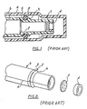
- A typical prior art device (Figs. 1 and 2) includes an outer container (a) which slidably receives a hollow plunger (b). A filter (c) is disposed near the end of the hollow plunger (b) and is retained there by a retainer ring (d) ultrasonically welded to the inside of the hollow plunger (b). Typically, an O-ring (e) is disposed in an annular groove (f) circumscribing the hollow plunger (b). The annular groove (f) is bounded and defined by shoulder portions (g) and (h) of increased diameter which prevent the O-ring (e) from moving with respect to the hollow plunger (b).
- A major drawback of filtration devices of this type is the inability to manufacture them on straight-pull molds due to the annular groove (f) which makes it impossible to remove this part from a straight-pull mold. Consequently, previously known filtration devices have been manufactured in side action or two-part mold cavities divided longitudinally in half. As a result of two-part molds, mismatches known as parting lines (s) are inevitable along the seam joining the two halves. Even though mismatch flaws may only be on the order of a few thousandths of an inch, this can be enough to cause the O-ring (e) to seat improperly in the annular groove (f) and cause a leak. While flaws of this magnitude generally will not permit liquids to pass, they often will permit air to pass, causing a poor seal. A poor air seal compromises the pressurization of trapped air essential to good sample filtrate delivery in differential filtration devices.
- In addition, heat generated by the ultrasonic welding of the retaining ring (d) to the end of the hollow plunger (b) can often damage the filter (c) which is adjacent thereto. Moreover, the pressure with which the ring (d) compresses the filter (c) cannot be adequately controlled. Insufficient or non-uniform pressure permits bypass leaks, while excessive pressure can damage the filter.
- The pressure invention overcomes these disadvantages of the prior art filtration devices by providing a sample filtration device manufactured on straight-pull molds to avoid mismatch flaws associated with the prior art devices. The invention also overcomes the disadvantages of ultrasonic welding by providing friction means for retaining the filter media within the core of the hollow plunger.
- In one aspect, the present invention comprises an improved differential pressure sample filtration apparatus. An outer container, closed at one end for holding a fluid sample for filtering, slidably receives a hollow plunger. The hollow plunger comprises two pieces: a first piece or collector portion having an annular shoulder thereon; and a second piece or retaining portion having a first annular ring. The retaining portion is affixed to the collector portion such that the annular shoulder of the collector portion and the first annular ring of the retaining portion cooperate to form the sides of an annular groove which retains a sealing means. The sealing means may comprise any structure capable of achieving a fluid seal between the outer container and the hollow plunger, for example, an O-ring or flat washer. A filtering means is disposed near one end of the plunger for filtering fluid from the outer container into an inner collecting means in the hollow plunger, as the plunger is inserted into the outer container.
- Preferably, the retaining portion also includes a plurality of legs connecting the first annular ring to a second annular ring which is smaller in diameter and axially spaced from the first annular ring. The second annular ring is dimensioned to fit inside the hollow portion of the plunger to retain the filter media in place. Ideally, the retaining portion is affixed to the collector portion by means of friction fit or "snap fit" between the second annular ring and the interior of the hollow plunger.
- In another aspect, the invention comprises a method for forming and assembling the components of the filtration device using straight-pull molds, which method eliminates leaking due to parting line mismatch flaws. According to the method of the invention, a collector portion of the plunger and a retaining portion of the plunger are formed separately, each from a distinctly configured straight-pull mold, and are assembled so that an annular shoulder on the collector portion cooperates with an annular face on the retaining portion to form the annular groove in which the sealing means is disposed. Preferably, the retaining portion and the collector portion remain engaged due to friction between a second annular ring dimensioned to frictionally engage the interior of the collector portion.
- A better understanding of the invention can be had by reference to the following detailed description of a preferred embodiment when read in conjunction with the accompanying drawings in which like reference numerals refer to like parts throughout the several views and in which:
- Figure 1 is a longitudinal cross-section of a filtration device known in the prior art;
- Figure 2 is an exploded perspective view of the plunger portion of the filtration device of Figure 1;
- Figure 3 is a longitudinal cross-sectional view of the filtration device of the present invention;
- Figure 4 is an exploded perspective view of the plunger portion of the invention;
- Figure 5 is a cross-sectional view taken substantially along line 5 - 5 of Figure 3;
- Figure 6 is a bottom plan view of a portion of the invention; and
- Figure 7 is a diagrammatic representation of a straight-pull mold employed in the invention.
- In Figure 3, the
filtration device 10 is depicted in longitudinal cross-section and comprises a cylindricalouter container 12 into which is slidably received a cylindrical, hollow plunger. The hollow plunger comprises a first piece or collectingportion 14, the upper end of which (as viewed in Figures 3 and 4) is closed by acap 16. A second piece of the plunger, a retaining portion 18 (somewhat resembling and herein referred to as a "crown"), is shown at the opposite end of thecollector portion 14. - As shown in Figures 3 and 5, the
outer container 12 comprises a cylindrical tube having inner and outer walls. Thecontainer 12 is open at a top end and closed at a bottom end. A section of thecontainer 12 near the bottom end preferably includes a radially reducedportion 19 and the interior face of the bottom end includes a raisedbump 20 for a reason to be subsequently discussed. Circumferentially spaced in the interior wall of thecontainer 12, just above the reducedportion 19, are formed a plurality of raisednubs 21 which serve a purpose to be described below. - The collector portion 14 (Figures 3, 4 and 5) similarly comprises a cylindrical tube but is open at both ends to form a hollow passageway or collecting chamber in the interior of the plunger. The exterior of the lower or inserted end (as viewed in Figures 3 and 4) of the
collector piece 14 also has a reduceddiameter portion 22 forming anannular shoulder 23. The interior lower end of thecollector portion 14 housesfilter media 24 and may or may not have a correspondingly reduced portion. - The
filter media 24 may be single or multiple layer and comprises any known filtering media including, but not limited to, paper, glass fiber, cellulose, and nitrocellulose. Depth filters are generally preferred over membrane filters due to their ability to remove greater quantities of particulate matter without becoming occluded. Especially preferred for most applications is fiberglass combined with polypropylene, however, different media may be preferred, depending on the application. - The
filter media 24 is held in place from above by anannular ledge 26 formed in the interior walls of thecollector portion 14 and, optionally, bycross bars 28 extending diametrically across the opening formed by theannular ledge 26. Theannular ledge 26 and, if necessary, thecross bars 28 support thefilter media 24 against the pressurized sample which must be filtered as the plunger is inserted into theouter container 12. - From below, the
filter media 24 is supported by the retaining portion ofcrown 18. As best shown in Figures 4 and 6, thecrown 18 comprises a firstannular ring 30 and a secondannular ring 32 which are joined together by a plurality oflongitudinal legs 34. The firstannular ring 30 is larger in diameter and is dimensioned to fit snugly over the reduceddiameter portion 22 of thecollector piece 14. Conversely, the secondannular ring 32 is smaller in diameter and is dimensioned to fit snugly inside the interior wall of the reducedportion 22 of thecollector piece 14. Accordingly, thelegs 34 are somewhat L-shaped. As best seen in Figures 3 and 4, thelegs 34 axially space the secondannular ring 32 from the firstannular ring 30 which gives thecrown 18 its characteristic appearance. Furthermore, the secondannular ring 32 includes a portion that extends axially upward from the foot of theleg 34 so that it can be inserted into the hollow interior of the reduceddiameter portion 22 of thecollector portion 14 to retain thefilter media 24 in position. Preferably, circumferentially spaced raisednubs 33 are disposed on either the outside of the second annular ring 32 (see Fig. 4) or the inside of the reducedportion 22 below the annular ledge 26 (not shown). The other of thering 32 or inside ofportion 22 has depressions (not shown) corresponding to thenubs 33 to securely lock one to the other. - As best seen in Figure 3, the
legs 34 have a length slightly less than the axial length of the reduceddiameter portion 22 which leaves a gap between the topaxial face 36 of the firstannular ring 30 and theannular shoulder 23 formed by the reducedportion 22 of thecollector piece 14. The gap defines an annular groove about the periphery of the plunger into which an O-ring 40 is securely seated. In this manner, the O-ring 40 slides with the plunger as it is inserted into theouter container 12 so that a fixed quantity of air is trapped in theouter container 12 and forces the sample through thefilter media 24. - While the preferred embodiment of the
crown 18 has been described, the invention also contemplates other straight-pull molded retaining portions secured to acollector portion 14 by suitable means and having an annular face axially spaced from theannular shoulder 23 to form an annular groove. A second ring, distinct or continuous with the retaining portion, can optionally form the filter retaining means. - It will be apparent to those skilled in the art that the gap between the
annular shoulder 23 and the topaxial face 36 is equivalent in function to the annular groove (f) of the prior art defined by the raised portions (g) and (h) as shown in Figures 1 and 2. However, by forming the gap from two components (ie. thecollector portion 14 and thecrown portion 18 of the plunger), it is possible to achieve thefiltration device 10 which can be molded from straight-pull molds to eliminate mismatch flaws or parting lines inherent in two-piece or side action molds. By eliminating these mismatch flaws, it is possible to decrease the chances that a particular plunger will have an air leak past the O-ring 40. - Each of the major components of the
device 10, namely theouter container 12, thecollector piece 14 and thecrown 18, is made of a relatively rigid substance such as plastic, polypropylene or polyethylene. These components may all be made of the same material. An especially preferred substance is polypropylene because it is easily molded by injection molding techniques and relatively inert to the assay. Ideally, the material is flexible enough and the dimensions small enough to permit thenubs 21 to be formed in spite of the shear action of the mold. - A typical mold (Figure 7) for forming the
collector portion 14 of the plunger comprises acavity 50 cut into ablock 52. Thecavity 50 is dimensioned to correspond to the outer wall of the collector portion and is open at the top. The bottom of thecavity 50 can be formed by theblock 52, but more conveniently is formed by apin 53 inserted into thecavity 50 to a predetermined position. Theblock 52 also has a port orgate 54 opening between thecavity 50 and asource 56 of molten plastic to permit injection molding of the component. Acore 58 is inserted into the center of thecavity 50 and is dimensioned to correspond with the interior dimensions of thecollector portion 14. Thecore 58 is centered within thecavity 50 by means ofspacers 60 which also can be used to remove the formedcollector piece 14 from thecentral core 58 by sharp downward pressure. Thepin 53 is centered by a spacer plate orcollar 62, which may be integral with theblock 52 or separate. - The
crown 18 can be be formed similarly from a straight-pull mold having a cavity and central core slightly different than those of Figure 7 but which can easily be determined by one skilled in the art. The retaining portion ofcrown 18 is then slid over the reduceddiameter portion 22 of thecollector portion 14 and locked into place by frictional engagement of thenubs 33. The retainer portion forms part of the annular groove for the O-ring 40 and, simultaneously, holds thefilter media 24 in place. - In use, a liquid sample to be filtered is placed in the bottom of the reduced
diameter portion 20 of theouter container 12. The plunger is inserted filter end first into the open end of theouter container 12 and the O-ring 40 sealingly engages the inner wall to form an air-tight seal between theouter container 12 and theplunger 14. As the plunger is depressed further into theouter container 12, air is forced through thefilter media 24 and escapes through the looselyfitting cap 16. - Once the plunger reaches the surface of the sample fluid to be filtered, a fixed quantity of air is trapped between the O-
ring 40 and the fluid level and, upon further depression of the plunger this trapped air is compressed. The pressurized air in turn forces the fluid sample through thefilter media 24 and into the collecting chamber in the interior of the hollow plunger. As the reduceddiameter portion 22 of the plunger is pushed into the reduceddiameter portion 20 of theouter container 12, the trapped quantity of air is forced into a smaller volume which multiplies its compressive effect on the fluid to deliver as much sample as possible through thefiltering media 24. This arrangement increases the efficiency of filtration which is important for small volume samples. - The
bump 20 at the bottom end of theouter container 12, by occupying space inside the secondannular ring 32, also serves to decrease the available space for trapped air, thereby to deliver as much sample filtrate as possible. - Filtration is complete when the plunger hits the bottom end of the
outer container 12. Simultaneously, the O-ring 40 snaps past thenubs 21 formed in the inner wall ofcontainer 12 to lock the two components together. This feature permits thick and thin samples alike to be filtered without the need for holding the components together manually. This is advantageous since some samples take longer than others to completely filter. - When filtration is complete, the filtrate can be poured from the open end of the hollow plunger upon removal of the
cap 16. Alternatively, additional reagents can be added to the filtered sample in the inner collector portion to further process the sample prior to pouring. Filtered sample can then be poured into any desired assay format without including undesired particulate matter present in the original sample. - The foregoing description of the preferred embodiment has been given for purposes of illustration only and no unnecessary limitations should be understood therefrom. Rather, the invention is intended to be limited only by the following claims:
- Where technical features mentioned in any claim are followed by reference signs, those reference signs have been included for the sole purpose of increasing the intelligibility of the claims and accordingly, such reference signs do not have any limiting effect on the scope of each element identified by way of example by such reference signs.
Claims (10)
an outer container for receiving a fluid for filtering; and
a hollow plunger dimensioned to be slidably received in said outer container and comprising:
a first piece having at one end a reduced diameter portion forming an annular shoulder, means for collecting fluid filtrate and filter means disposed between said one end of the plunger and said means for collecting fluid filtrate; and
a second piece having an annular axial face and being dimensioned to be secured to said first piece such that the annular axial face and the annular shoulder cooperate to form an annular groove about said plunger, said annular groove being adapted for receiving a sealing means for forming a fluid seal between the outer container and the hollow plunger,
wherein said first and second pieces can be formed in straight-pull molds.
a first annular ring dimensioned to slidably fit over said one end of the first piece;
a second, smaller annular ring dimensioned to slidably fit into the hollow portion of said one end of the first piece to abut said filter means; and
a plurality of legs connecting said first annular ring to said second annular ring.
a plunger having a first collector portion and a second retaining portion, each of said portions being formed on straight-pull molds and each defining part of said annular groove.
Applications Claiming Priority (2)
| Application Number | Priority Date | Filing Date | Title |
|---|---|---|---|
| US07/148,260 US4891134A (en) | 1988-01-25 | 1988-01-25 | Sample filtration device |
| US148260 | 1988-01-25 |
Publications (2)
| Publication Number | Publication Date |
|---|---|
| EP0325910A1 true EP0325910A1 (en) | 1989-08-02 |
| EP0325910B1 EP0325910B1 (en) | 1993-09-29 |
Family
ID=22524998
Family Applications (1)
| Application Number | Title | Priority Date | Filing Date |
|---|---|---|---|
| EP89100039A Expired - Lifetime EP0325910B1 (en) | 1988-01-25 | 1989-01-03 | Improved sample filtration device |
Country Status (5)
| Country | Link |
|---|---|
| US (1) | US4891134A (en) |
| EP (1) | EP0325910B1 (en) |
| JP (1) | JPH024408A (en) |
| CA (1) | CA1321953C (en) |
| DE (1) | DE68909428T2 (en) |
Cited By (9)
| Publication number | Priority date | Publication date | Assignee | Title |
|---|---|---|---|---|
| WO1993001306A1 (en) * | 1991-07-09 | 1993-01-21 | Goumeniouk Alexander P | Diagnostic kits and methods for making granulocyte cell counts |
| EP0542655A1 (en) * | 1991-11-12 | 1993-05-19 | Institut Jacques Boy | Device for the separation and determination of agglutinated erythrocytes in a single step |
| EP0643944A1 (en) * | 1993-09-22 | 1995-03-22 | B. Braun Melsungen Ag | Blood sampling device |
| WO2004029406A1 (en) * | 2002-09-24 | 2004-04-08 | Cybersense Biosystems Limited | Soil sampling and extraction unit |
| WO2010133771A3 (en) * | 2009-05-22 | 2011-04-07 | Valtion Teknillinen Tutkimuskeskus | Sample port, multi-layer filter, sampling method, and use of a sample port in sampling |
| TWI385031B (en) * | 2007-07-02 | 2013-02-11 | Ind Tech Res Inst | Apparatus and process for washing cell, tissue, or biological material |
| US20150076069A1 (en) * | 2013-09-13 | 2015-03-19 | Scientific Plastic Products, Inc. | Filter vial with limited piston stroke |
| US11885722B2 (en) | 2021-01-06 | 2024-01-30 | Hero Scientific Ltd. | Filtration sampling devices |
| WO2024013747A3 (en) * | 2022-07-13 | 2024-02-22 | Hero Scientific Ltd. | Filtration sampling and testing devices |
Families Citing this family (53)
| Publication number | Priority date | Publication date | Assignee | Title |
|---|---|---|---|---|
| US4990253A (en) * | 1988-01-25 | 1991-02-05 | Abbott Laboratories | Fluid sample filtration device |
| DE8808138U1 (en) * | 1988-06-24 | 1988-10-27 | Ballies, Uwe, Dr. Med., 2300 Kiel, De | |
| US5114858A (en) * | 1990-06-26 | 1992-05-19 | E. I. Du Pont De Nemours And Company | Cellular component extraction process in a disposable filtration vessel |
| US5364597A (en) * | 1991-03-13 | 1994-11-15 | Cytyc Corporation | Apparatus for collection and transfer of particles |
| US5368729A (en) * | 1993-07-23 | 1994-11-29 | Whatman, Inc. | Solid phase extraction device |
| US5976824A (en) * | 1993-11-24 | 1999-11-02 | Abbott Laboratories | Method and apparatus for collecting a cell sample from a liquid specimen |
| US5578459A (en) * | 1993-11-24 | 1996-11-26 | Abbott Laboratories | Method and apparatus for collecting a cell sample from a liquid specimen |
| US5567309A (en) * | 1994-02-14 | 1996-10-22 | Alcott Chromatography, Inc. | Self-filtration cap |
| WO1996005902A1 (en) * | 1994-08-23 | 1996-02-29 | John Bates | Liquid-liquid extraction |
| CA2232673C (en) | 1995-09-22 | 2008-11-18 | Geoffrey L. Kidd | Container for drying biological samples, method of making such container, and method of using same |
| JP2859845B2 (en) * | 1996-05-09 | 1999-02-24 | 照明 伊藤 | Serum collection aid |
| US6312648B1 (en) | 1998-01-12 | 2001-11-06 | The United States Of America As Represented By The Department Of Health And Human Services | Applicator system |
| US6221655B1 (en) * | 1998-08-01 | 2001-04-24 | Cytosignal | Spin filter assembly for isolation and analysis |
| US6635430B1 (en) | 1999-07-16 | 2003-10-21 | Dupont Pharmaceuticals Company | Filtrate plate device and reversible-well plate device |
| US7176034B2 (en) * | 2002-07-03 | 2007-02-13 | St. Joseph's Healthcare | Apparatus and method for filtering biological samples |
| US20040048392A1 (en) * | 2002-09-09 | 2004-03-11 | The Gov't Of The U.S.A As Represented By The Secretary Of The Dept.Of Health And Human Services | Container for drying biological samples, method of making such container, and method of using same |
| WO2005050167A2 (en) * | 2003-11-14 | 2005-06-02 | Oakville Hong Kong Co., Limited | Rapid sample collection and analysis device |
| CN1989409A (en) * | 2004-05-27 | 2007-06-27 | 荣研化学株式会社 | Biological sample collecting implement and method of collecting biological sample |
| WO2009021197A2 (en) | 2007-08-08 | 2009-02-12 | O'brien Paul W | Portable drinking water purification device |
| US9339818B2 (en) * | 2008-01-09 | 2016-05-17 | Screencell | Device and method for isolating and cultivating live cells on a filter or extracting the genetic material thereof |
| US8465654B2 (en) * | 2008-03-07 | 2013-06-18 | Bekaert Advanced Filtration Sa | Filter candle and mesh pack with a deformable seal, and method of filtering molten or dissolved polymers |
| US7790117B2 (en) | 2008-03-21 | 2010-09-07 | Scientific Plastic Products, Inc. | Filter vial |
| US8394268B2 (en) * | 2008-08-08 | 2013-03-12 | Miracle Straw Corporation, Inc. | Double chamber water purification device |
| US8318011B2 (en) | 2008-10-15 | 2012-11-27 | Miracle Straw Corporation, Inc. | Portable drinking water purification device |
| CN201404734Y (en) * | 2009-04-28 | 2010-02-17 | 厦门市毕恩生物技术有限公司 | Bottom control type sample filtering container |
| US8425771B2 (en) | 2009-07-24 | 2013-04-23 | Miracle Straw Corporation, Inc. | Double chamber water purification device |
| JP5330144B2 (en) * | 2009-07-31 | 2013-10-30 | 花王株式会社 | Trace solid sample analyzer |
| US8313644B2 (en) * | 2010-01-13 | 2012-11-20 | OZOlab | Bottle with an integrated filtration assembly that is manually operated using a plunger |
| US9475709B2 (en) | 2010-08-25 | 2016-10-25 | Lockheed Martin Corporation | Perforated graphene deionization or desalination |
| US8919385B2 (en) | 2010-11-24 | 2014-12-30 | Pall Corporation | Manifold plates and fluid treatment arrangements including manifold plates |
| US9193587B2 (en) * | 2011-07-13 | 2015-11-24 | Lockheed Martin Corporation | System and method for water purification and desalination |
| US8322539B1 (en) | 2012-03-02 | 2012-12-04 | Scientific Plastic Products, Inc. | Filter vial |
| US9744617B2 (en) | 2014-01-31 | 2017-08-29 | Lockheed Martin Corporation | Methods for perforating multi-layer graphene through ion bombardment |
| US10980919B2 (en) | 2016-04-14 | 2021-04-20 | Lockheed Martin Corporation | Methods for in vivo and in vitro use of graphene and other two-dimensional materials |
| US9834809B2 (en) | 2014-02-28 | 2017-12-05 | Lockheed Martin Corporation | Syringe for obtaining nano-sized materials for selective assays and related methods of use |
| US10653824B2 (en) | 2012-05-25 | 2020-05-19 | Lockheed Martin Corporation | Two-dimensional materials and uses thereof |
| US10376845B2 (en) | 2016-04-14 | 2019-08-13 | Lockheed Martin Corporation | Membranes with tunable selectivity |
| EP2695656A1 (en) * | 2012-08-09 | 2014-02-12 | F. Hoffmann-La Roche AG | Method and separation device for separating a filtrate from a sample liquid |
| TW201504140A (en) | 2013-03-12 | 2015-02-01 | Lockheed Corp | Method for forming perforated graphene with uniform aperture size |
| US9572918B2 (en) | 2013-06-21 | 2017-02-21 | Lockheed Martin Corporation | Graphene-based filter for isolating a substance from blood |
| WO2015070712A1 (en) * | 2013-11-14 | 2015-05-21 | Abon Biopharm (Hangzhou) Co., Ltd. | A device and method for using the device |
| CA2938305A1 (en) | 2014-01-31 | 2015-08-06 | Lockheed Martin Corporation | Processes for forming composite structures with a two-dimensional material using a porous, non-sacrificial supporting layer |
| CN105940479A (en) | 2014-01-31 | 2016-09-14 | 洛克希德马丁公司 | Methods for perforating two-dimensional materials using a broad ion field |
| JP2017512129A (en) | 2014-03-12 | 2017-05-18 | ロッキード・マーチン・コーポレーション | Separation membranes formed from perforated graphene |
| EP3188823A4 (en) | 2014-09-02 | 2018-04-25 | Lockheed Martin Corporation | Hemodialysis and hemofiltration membranes based upon a two-dimensional membrane material and methods employing same |
| AU2016303048A1 (en) | 2015-08-05 | 2018-03-01 | Lockheed Martin Corporation | Perforatable sheets of graphene-based material |
| AU2016303049A1 (en) | 2015-08-06 | 2018-03-01 | Lockheed Martin Corporation | Nanoparticle modification and perforation of graphene |
| CA3020686A1 (en) | 2016-04-14 | 2017-10-19 | Lockheed Martin Corporation | Method for treating graphene sheets for large-scale transfer using free-float method |
| JP2019521055A (en) | 2016-04-14 | 2019-07-25 | ロッキード・マーチン・コーポレーション | Selective interface relaxation of graphene defects |
| EP3442786A4 (en) | 2016-04-14 | 2020-03-18 | Lockheed Martin Corporation | Two-dimensional membrane structures having flow passages |
| EP3443329A4 (en) | 2016-04-14 | 2020-04-08 | Lockheed Martin Corporation | Methods for in situ monitoring and control of defect formation or healing |
| MY195849A (en) * | 2018-09-05 | 2023-02-23 | Kin Mun Chin | Device for Filtering |
| CN113588333B (en) * | 2021-08-20 | 2023-11-17 | 中国地质科学院水文地质环境地质研究所 | Layering processing apparatus of groundwater collection and sample |
Citations (9)
| Publication number | Priority date | Publication date | Assignee | Title |
|---|---|---|---|---|
| US3481477A (en) | 1965-03-02 | 1969-12-02 | Andrew F Farr | Apparatus for filtering out clear liquid from suspended solids |
| US3693804A (en) | 1969-10-13 | 1972-09-26 | Douglas U Grover | Pressure differential filtering apparatus and method |
| US3969250A (en) | 1975-03-10 | 1976-07-13 | Farr Andrew F | Apparatus for preparing liquid samples for analysis in automatic analyzers |
| US3970565A (en) | 1973-11-27 | 1976-07-20 | Aktiebolaget Stille-Werner | Separating and filtering device |
| US4035150A (en) | 1975-09-24 | 1977-07-12 | The United States Of America As Represented By The Secretary Of The Department Of Health, Education And Welfare | Test for occult blood in an emulsified aqueous/organic system |
| US4035294A (en) * | 1975-05-23 | 1977-07-12 | Denver Chemical Manufacturing Company | Pressure differential filtering device and method |
| GB2088699A (en) * | 1980-11-17 | 1982-06-16 | Pfeiffer Ohler Eisen Theob | Serving tray |
| FR2536671A1 (en) * | 1982-11-26 | 1984-06-01 | Sartorius Gmbh | FILTERING APPARATUS FOR LIQUIDS OF THE MEMBRANE STATIC TYPE |
| DE3542331A1 (en) * | 1985-11-29 | 1987-06-04 | Sarstedt Kunststoff | Filter apparatus for liquids |
Family Cites Families (8)
| Publication number | Priority date | Publication date | Assignee | Title |
|---|---|---|---|---|
| US3325576A (en) * | 1964-02-03 | 1967-06-13 | Kessler Milton | Method of making unitary plastic sealing cap |
| US3512940A (en) * | 1968-12-30 | 1970-05-19 | Justin J Shapiro | Test tube filter device |
| IL58943A (en) * | 1979-12-12 | 1983-05-15 | Cais Michael | Method and device for mass transfer operations in immunoassays and other applications |
| US4286640A (en) * | 1980-01-21 | 1981-09-01 | Abbott Laboratories | Tamperproof port cover |
| IL60645A (en) * | 1980-07-21 | 1984-02-29 | Cais Michael | Method and device for mass transfer and separation through selective barriers |
| IL63363A (en) * | 1981-07-20 | 1986-08-31 | Cais Michael | Non-centrifugation method for immunoassay of materials |
| US4568083A (en) * | 1982-11-15 | 1986-02-04 | Miller Richard E | Game ball |
| US4800020A (en) * | 1987-05-21 | 1989-01-24 | Xydex Corporation | Piston filtering device |
-
1988
- 1988-01-25 US US07/148,260 patent/US4891134A/en not_active Expired - Fee Related
-
1989
- 1989-01-03 DE DE89100039T patent/DE68909428T2/en not_active Expired - Fee Related
- 1989-01-03 EP EP89100039A patent/EP0325910B1/en not_active Expired - Lifetime
- 1989-01-23 JP JP1014938A patent/JPH024408A/en active Pending
- 1989-01-24 CA CA000589055A patent/CA1321953C/en not_active Expired - Fee Related
Patent Citations (9)
| Publication number | Priority date | Publication date | Assignee | Title |
|---|---|---|---|---|
| US3481477A (en) | 1965-03-02 | 1969-12-02 | Andrew F Farr | Apparatus for filtering out clear liquid from suspended solids |
| US3693804A (en) | 1969-10-13 | 1972-09-26 | Douglas U Grover | Pressure differential filtering apparatus and method |
| US3970565A (en) | 1973-11-27 | 1976-07-20 | Aktiebolaget Stille-Werner | Separating and filtering device |
| US3969250A (en) | 1975-03-10 | 1976-07-13 | Farr Andrew F | Apparatus for preparing liquid samples for analysis in automatic analyzers |
| US4035294A (en) * | 1975-05-23 | 1977-07-12 | Denver Chemical Manufacturing Company | Pressure differential filtering device and method |
| US4035150A (en) | 1975-09-24 | 1977-07-12 | The United States Of America As Represented By The Secretary Of The Department Of Health, Education And Welfare | Test for occult blood in an emulsified aqueous/organic system |
| GB2088699A (en) * | 1980-11-17 | 1982-06-16 | Pfeiffer Ohler Eisen Theob | Serving tray |
| FR2536671A1 (en) * | 1982-11-26 | 1984-06-01 | Sartorius Gmbh | FILTERING APPARATUS FOR LIQUIDS OF THE MEMBRANE STATIC TYPE |
| DE3542331A1 (en) * | 1985-11-29 | 1987-06-04 | Sarstedt Kunststoff | Filter apparatus for liquids |
Cited By (13)
| Publication number | Priority date | Publication date | Assignee | Title |
|---|---|---|---|---|
| WO1993001306A1 (en) * | 1991-07-09 | 1993-01-21 | Goumeniouk Alexander P | Diagnostic kits and methods for making granulocyte cell counts |
| EP0542655A1 (en) * | 1991-11-12 | 1993-05-19 | Institut Jacques Boy | Device for the separation and determination of agglutinated erythrocytes in a single step |
| FR2688311A1 (en) * | 1991-11-12 | 1993-09-10 | Boy Inst Jacques | PROCESS FOR THE EVIDENCE OF ERYTHROCYTE AGGLUTINATES. |
| EP0643944A1 (en) * | 1993-09-22 | 1995-03-22 | B. Braun Melsungen Ag | Blood sampling device |
| WO2004029406A1 (en) * | 2002-09-24 | 2004-04-08 | Cybersense Biosystems Limited | Soil sampling and extraction unit |
| TWI385031B (en) * | 2007-07-02 | 2013-02-11 | Ind Tech Res Inst | Apparatus and process for washing cell, tissue, or biological material |
| CN102575215A (en) * | 2009-05-22 | 2012-07-11 | Vtt科技研究中心 | Sample port, multi-layer filter, sampling method, and use of a sample port in sampling |
| US8329476B2 (en) | 2009-05-22 | 2012-12-11 | Teknologian Tutkimuskeskus Vtt | Sample port, multi-layer filter, sampling method, and use of a sample port in sampling |
| WO2010133771A3 (en) * | 2009-05-22 | 2011-04-07 | Valtion Teknillinen Tutkimuskeskus | Sample port, multi-layer filter, sampling method, and use of a sample port in sampling |
| US20150076069A1 (en) * | 2013-09-13 | 2015-03-19 | Scientific Plastic Products, Inc. | Filter vial with limited piston stroke |
| US11885722B2 (en) | 2021-01-06 | 2024-01-30 | Hero Scientific Ltd. | Filtration sampling devices |
| US11921018B2 (en) | 2021-01-06 | 2024-03-05 | Hero Scientific Ltd. | Filtration sampling devices |
| WO2024013747A3 (en) * | 2022-07-13 | 2024-02-22 | Hero Scientific Ltd. | Filtration sampling and testing devices |
Also Published As
| Publication number | Publication date |
|---|---|
| DE68909428D1 (en) | 1993-11-04 |
| DE68909428T2 (en) | 1994-03-03 |
| CA1321953C (en) | 1993-09-07 |
| JPH024408A (en) | 1990-01-09 |
| EP0325910B1 (en) | 1993-09-29 |
| US4891134A (en) | 1990-01-02 |
Similar Documents
| Publication | Publication Date | Title |
|---|---|---|
| EP0325910B1 (en) | Improved sample filtration device | |
| US4990253A (en) | Fluid sample filtration device | |
| CA2719056C (en) | Filter vial having a tubular piston a retainer cup and a filter | |
| US4444661A (en) | Filter device | |
| EP0059284B1 (en) | Disposable, one-piece filter unit and method of manufacturing the same | |
| US6045757A (en) | Membrane filter pipette tip | |
| US5873967A (en) | Method for making a vaccum filter device | |
| US8978896B2 (en) | Method for filtering liquid using a filter vial | |
| US3832141A (en) | Pressure differential filtering apparatus | |
| US3693804A (en) | Pressure differential filtering apparatus and method | |
| US5567309A (en) | Self-filtration cap | |
| US4430213A (en) | Ultrafiltration unit | |
| US5202262A (en) | Apparatus for microbiological testing of liquids | |
| JP2015054246A (en) | Filter vial device with limited piston stroke and pharmaceutical production method | |
| US4309286A (en) | Lower sealing means for chromatographic column | |
| US20040247490A1 (en) | Universal filtration plate | |
| US5108709A (en) | Color-coded disposable-filter holder | |
| US5108599A (en) | Low pressure liquid filter cartridge and method of making | |
| JPH02184306A (en) | Disposable filter holder | |
| US3732981A (en) | Filtration column | |
| JPH0118178Y2 (en) | ||
| GB2184034A (en) | Spinnerette filter |
Legal Events
| Date | Code | Title | Description |
|---|---|---|---|
| PUAI | Public reference made under article 153(3) epc to a published international application that has entered the european phase |
Free format text: ORIGINAL CODE: 0009012 |
|
| AK | Designated contracting states |
Kind code of ref document: A1 Designated state(s): BE CH DE FR IT LI |
|
| 17P | Request for examination filed |
Effective date: 19900126 |
|
| 17Q | First examination report despatched |
Effective date: 19911001 |
|
| GRAA | (expected) grant |
Free format text: ORIGINAL CODE: 0009210 |
|
| AK | Designated contracting states |
Kind code of ref document: B1 Designated state(s): BE CH DE FR IT LI |
|
| REF | Corresponds to: |
Ref document number: 68909428 Country of ref document: DE Date of ref document: 19931104 |
|
| ET | Fr: translation filed | ||
| ITF | It: translation for a ep patent filed |
Owner name: MODIANO & ASSOCIATI S.R |
|
| PLBE | No opposition filed within time limit |
Free format text: ORIGINAL CODE: 0009261 |
|
| STAA | Information on the status of an ep patent application or granted ep patent |
Free format text: STATUS: NO OPPOSITION FILED WITHIN TIME LIMIT |
|
| 26N | No opposition filed | ||
| PGFP | Annual fee paid to national office [announced via postgrant information from national office to epo] |
Ref country code: FR Payment date: 19970113 Year of fee payment: 9 |
|
| PGFP | Annual fee paid to national office [announced via postgrant information from national office to epo] |
Ref country code: DE Payment date: 19970129 Year of fee payment: 9 |
|
| PGFP | Annual fee paid to national office [announced via postgrant information from national office to epo] |
Ref country code: BE Payment date: 19970206 Year of fee payment: 9 |
|
| PGFP | Annual fee paid to national office [announced via postgrant information from national office to epo] |
Ref country code: CH Payment date: 19970418 Year of fee payment: 9 |
|
| PG25 | Lapsed in a contracting state [announced via postgrant information from national office to epo] |
Ref country code: LI Free format text: LAPSE BECAUSE OF NON-PAYMENT OF DUE FEES Effective date: 19980131 Ref country code: FR Free format text: THE PATENT HAS BEEN ANNULLED BY A DECISION OF A NATIONAL AUTHORITY Effective date: 19980131 Ref country code: CH Free format text: LAPSE BECAUSE OF NON-PAYMENT OF DUE FEES Effective date: 19980131 Ref country code: BE Free format text: LAPSE BECAUSE OF NON-PAYMENT OF DUE FEES Effective date: 19980131 |
|
| BERE | Be: lapsed |
Owner name: ABBOTT LABORATORIES Effective date: 19980131 |
|
| REG | Reference to a national code |
Ref country code: CH Ref legal event code: PL |
|
| PG25 | Lapsed in a contracting state [announced via postgrant information from national office to epo] |
Ref country code: DE Free format text: LAPSE BECAUSE OF NON-PAYMENT OF DUE FEES Effective date: 19981001 |
|
| REG | Reference to a national code |
Ref country code: FR Ref legal event code: ST |
|
| PG25 | Lapsed in a contracting state [announced via postgrant information from national office to epo] |
Ref country code: IT Free format text: LAPSE BECAUSE OF NON-PAYMENT OF DUE FEES;WARNING: LAPSES OF ITALIAN PATENTS WITH EFFECTIVE DATE BEFORE 2007 MAY HAVE OCCURRED AT ANY TIME BEFORE 2007. THE CORRECT EFFECTIVE DATE MAY BE DIFFERENT FROM THE ONE RECORDED. Effective date: 20050103 |