EP0325682B1 - Bone screw - Google Patents
Bone screw Download PDFInfo
- Publication number
- EP0325682B1 EP0325682B1 EP88109604A EP88109604A EP0325682B1 EP 0325682 B1 EP0325682 B1 EP 0325682B1 EP 88109604 A EP88109604 A EP 88109604A EP 88109604 A EP88109604 A EP 88109604A EP 0325682 B1 EP0325682 B1 EP 0325682B1
- Authority
- EP
- European Patent Office
- Prior art keywords
- bone screw
- bone
- externally threaded
- threaded portion
- thread
- Prior art date
- Legal status (The legal status is an assumption and is not a legal conclusion. Google has not performed a legal analysis and makes no representation as to the accuracy of the status listed.)
- Expired - Lifetime
Links
Images


Classifications
-
- A—HUMAN NECESSITIES
- A61—MEDICAL OR VETERINARY SCIENCE; HYGIENE
- A61B—DIAGNOSIS; SURGERY; IDENTIFICATION
- A61B17/00—Surgical instruments, devices or methods, e.g. tourniquets
- A61B17/56—Surgical instruments or methods for treatment of bones or joints; Devices specially adapted therefor
- A61B17/58—Surgical instruments or methods for treatment of bones or joints; Devices specially adapted therefor for osteosynthesis, e.g. bone plates, screws, setting implements or the like
- A61B17/68—Internal fixation devices, including fasteners and spinal fixators, even if a part thereof projects from the skin
- A61B17/70—Spinal positioners or stabilisers ; Bone stabilisers comprising fluid filler in an implant
- A61B17/7058—Plates mounted on top of bone anchor heads or shoulders
-
- A—HUMAN NECESSITIES
- A61—MEDICAL OR VETERINARY SCIENCE; HYGIENE
- A61B—DIAGNOSIS; SURGERY; IDENTIFICATION
- A61B17/00—Surgical instruments, devices or methods, e.g. tourniquets
- A61B17/56—Surgical instruments or methods for treatment of bones or joints; Devices specially adapted therefor
- A61B17/58—Surgical instruments or methods for treatment of bones or joints; Devices specially adapted therefor for osteosynthesis, e.g. bone plates, screws, setting implements or the like
- A61B17/68—Internal fixation devices, including fasteners and spinal fixators, even if a part thereof projects from the skin
- A61B17/74—Devices for the head or neck or trochanter of the femur
- A61B17/742—Devices for the head or neck or trochanter of the femur having one or more longitudinal elements oriented along or parallel to the axis of the neck
-
- A—HUMAN NECESSITIES
- A61—MEDICAL OR VETERINARY SCIENCE; HYGIENE
- A61B—DIAGNOSIS; SURGERY; IDENTIFICATION
- A61B17/00—Surgical instruments, devices or methods, e.g. tourniquets
- A61B17/56—Surgical instruments or methods for treatment of bones or joints; Devices specially adapted therefor
- A61B17/58—Surgical instruments or methods for treatment of bones or joints; Devices specially adapted therefor for osteosynthesis, e.g. bone plates, screws, setting implements or the like
- A61B17/68—Internal fixation devices, including fasteners and spinal fixators, even if a part thereof projects from the skin
- A61B17/84—Fasteners therefor or fasteners being internal fixation devices
- A61B17/86—Pins or screws or threaded wires; nuts therefor
- A61B17/8605—Heads, i.e. proximal ends projecting from bone
-
- A—HUMAN NECESSITIES
- A61—MEDICAL OR VETERINARY SCIENCE; HYGIENE
- A61B—DIAGNOSIS; SURGERY; IDENTIFICATION
- A61B17/00—Surgical instruments, devices or methods, e.g. tourniquets
- A61B17/56—Surgical instruments or methods for treatment of bones or joints; Devices specially adapted therefor
- A61B17/58—Surgical instruments or methods for treatment of bones or joints; Devices specially adapted therefor for osteosynthesis, e.g. bone plates, screws, setting implements or the like
- A61B17/68—Internal fixation devices, including fasteners and spinal fixators, even if a part thereof projects from the skin
- A61B17/84—Fasteners therefor or fasteners being internal fixation devices
- A61B17/86—Pins or screws or threaded wires; nuts therefor
- A61B17/8625—Shanks, i.e. parts contacting bone tissue
- A61B17/863—Shanks, i.e. parts contacting bone tissue with thread interrupted or changing its form along shank, other than constant taper
Definitions
- the present invention relates to a bone screw for use in correcting damage or deformation to a bone or group of bones in a body.
- Bone screws are known in the medical profession. Typical uses for a bone screw are to treat a bone fracture, to attach a corrective device to parts of a fractured bone in the area adjacent to the fracture, or to attach a corrective device to a group of bones, such as a spinal column.
- U.S. Patent No. 4,653,481 discloses an advanced spine fixation system including a plurality of screw clamp assemblies inserted through the pedicle and vertebral body at the vertebra. Screw clamps are provided which have a coarse threaded portion for engaging a cancellous portion of a bone as well as a normal threaded portion for receiving a removable saddle assembly composed of two halves and each provided with apertures for the reception of rigid support rods.
- the screws and clamps are properly placed and a soft temporary master is formed which follows and replicates the contour of reference surfaces on the clamps. The temporary master is then used to form a master pattern which in turn is used to form the rigid rods to the determined contour.
- the rigid rods are then affixed to the clamp assemblies to provide the rigid support needed for spinal procedures.
- the screw clamps do not incorporate means to restrict movement of the screw clamps relative to the bone portion in a direction transverse to the longitudinal central axis of the screw clamps and to block effluence from the opening in the bone portion into which the screw clamp is inserted.
- U.S. Patent Nos. 2,121,193 and 2,570,465 each disclose a bone screw which has a threaded portion for engaging a cancellous portion of a bone.
- the threaded portion has a trailing face extending in a direction which is substantially perpendicular to the longitudinal axis of the bone screw.
- a bone screw disclosed in U.S. Patent No. 4,175,555 has two threads of different pitch distances for engaging bone tissue. Each of the two threads has a face, which is substantially perpendicular to the longitudinal axis of the bone screw, for applying a clamping force to fractured parts of a bone as the bone screw is advanced.
- U.S. Patent No. 3,997,138 discloses another bone screw for securing rods of a corrective device to a vertebra.
- the bone screw includes two threaded portions and a boss integrally formed on the bone screw.
- the boss is located between the two threaded portions.
- the boss maintains the rods spaced away from the vertebra.
- a washer having projections for extending into the vertebra is located between the boss and the vertebra to aid in stabilizing the bone screw in a cancellous bone.
- a bone screw similar to the bone screw disclosed in U.S. Patent No. 2,121,193, referred to above, may be used to secure a corrective device to a vertebra.
- a first threaded portion of the bone screw is threaded into a cancellous portion of the vertebra.
- a nut is threaded onto a second threaded portion of the bone screw projecting from the vertebra.
- a corrective device is received on the second threaded portion of the bone screw and placed against the nut.
- a second nut is then threaded onto the second threaded portion of the bone screw. The second nut is tightened against the corrective device to apply a clamping force to the corrective device for preventing movement of the corrective device relative to the bone screw.
- the bone screw Due to load being transmitted from the corrective device to the bone screw in a direction perpendicular to the longitudinal central axis of the bone screw, the bone screw tends to move relative to the vertebra or the second threaded portion tends to bend relative to the first threaded portion. This bending of the bone screw could result in a crack developing in the surface of the bone screw and eventual failure. Also, if the corrective device is not seated properly between the nuts, a localized bending stress concentrates in the bone screw adjacent the nuts and the bone screw may break.
- the present invention provides a bone screw as defined in claim 1.
- the bone screw has a thread configuration which provides solid mounting for the bone screw in a cancellous bone. A crest portion of the thread is impaled in the cancellous bone to increase the resistance to removal of the bone screw from the bone.
- the bone screw has increased strength in areas which are normally subjected to the highest stress and which are prone to breakage.
- the bone screw has a reference surface which aids the surgeon in determining when the bone screw has been advanced into the bone a desired distance.
- the bone screw has a combination retaining and seal section.
- the retaining and seal section has a relatively large area of engagement with an opening formed in the bone to restrict movement of the bone screw relative to the bone in a direction perpendicular to the longitudinal central axis of the bone screw.
- the retaining and seal section also tends to minimize bending of the bone screw.
- the large area of engagement between the bone and the retaining and seal section enables the bone screw to block the flow of fluid from an opening formed in the bone for the bone screw.
- a standard external thread convolution is formed on one end portion of the bone screw to receive a nut to attach the bone screw to a corrective device.
- a coarse external thread convolution is formed on the opposite end of the bone screw to engage a cancellous bone.
- the coarse thread convolution has leading and trailing faces.
- the leading face is angled rearwardly approximately 45 degrees relative to the longitudinal axis of the bone screw.
- the trailing face is angled rearwardly approximately 80 degrees relative to the longitudinal axis of the bone screw to intersect the leading face of the same thread convolution and form a crest.
- the leading and trailing faces of adjacent thread convolutions intersect in an arcuate root portion having a radius of curvature.
- the crest is offset rearwardly of the forwardmost portion of the trailing face by a distance less than the radius of curvature of the arcuate root portion to form a recess for a portion of the cancellous bone to project into to form a solid mounting for the bone screw in the bone.
- a connecting member of a corrective device is received on the bone screw and a nut is threaded onto the standard thread convolution.
- a tensile force is imparted through the bone screw, and the crests of the coarse thread convolution are impaled in the cancellous bone as the bone screw is urged to move in a direction towards the nut.
- the bone screw is used to attach a connecting member of a corrective device to a cancellous bone.
- the bone screw includes an elongate shank having a longitudinal central axis.
- a first externally threaded portion is used for attaching the connecting member to the bone screw.
- a second externally threaded portion is for threaded engagement with a surface defining an opening in bone to attach the bone screw to the bone.
- a cylindrical body portion on the shank is located between the first and second externally threaded portions.
- the body portion has a diameter substantially equal to the crest diameter of the threads on the second externally threaded portion.
- the length of the body portion is less than the pitch of the second externally threaded portion.
- the body portion engages a portion of the surface defining the opening in the bone to restrict movement of the bone screw relative to the bone in a direction transverse to the longitudinal central axis of the shank.
- the body portion also blocks fluid flow from the opening in the bone.
- the thread convolution of the second externally threaded portion located adjacent the body portion has a root with a radius greater than the radius of the root of the other thread convolutions of the second externally threaded portion.
- a seat portion is located on the body portion adjacent the first externally threaded portion. The seat portion has a surface for engaging the connecting member to establish the axial location of the connecting member along the bone screw.
- a shoulder portion is located between the seat portion and the body portion.
- the shoulder portion has a tapering circular surface with a diameter which increases as the shoulder portion extends in a direction from the body portion toward the seat portion.
- a second shoulder portion is located between the seat portion and the first externally threaded portion. The second shoulder portion has a tapering circular surface which increases in diameter as the second shoulder portion extends in a direction from the first threaded portion toward the seat portion.
- FIG. 1 An embodiment of a bone screw 110 according to the present invention is illustrated in Fig. 1.
- the bone screw 110 is for use with a connecting member 120 (Fig. 3) of a corrective device for connecting bone portions together.
- the bone screw 110 is threaded into a bone portion 122 to connect the connecting member 120 with the bone portion.
- the bone portions may be parts of a fractured bone or may be different bones of a group of bones, such as vertebrae of a spinal column.
- the bone screw 110 is made from a material compatible with human tissue, such as surgical grade stainless steel or titanium.
- the bone screw 110 includes an elongate cylindrical shank 132 (Fig. 5) having a longitudinal central axis B.
- the bone screw 110 has an externally threaded portion 142 integrally formed on the shank 132 and extending longitudinally along a portion of the shank.
- the threaded portion 142 receives a standard internally threaded nut 146 (Fig. 3) to secure the connecting member 120 to the bone screw 110.
- the bone screw 110 also has another externally threaded portion 144 integrally formed on the shank 132 and extending longitudinally along another portion of the shank.
- the threaded portion 144 is for connecting the bone screw 110 to a cancellous bone portion 122, such as a vertebra, as illustrated in Figs. 2-4.
- the configuration of the coarse threaded portion 144 is illustrated in detail in Figs. 6 and 7
- the coarse threaded portion 144 has a leading face 46 and a trailing face 48 relative to the direction the bone screw 110 advances into the bone portion 122 to the left as viewed in Figs. 6 and 7.
- the leading face 46 faces forward in a direction away from the standard threaded portion 142 and is angled to the rear of the bone screw between 40° and 50°.
- the leading face 46 is disposed at a 45° angle relative to a line 52 normal to the longitudinal central axis A, or 45 degrees relative to the longitudinal central axis.
- the trailing face 48 faces toward the standard threaded portion and is angled to the rear of the bone screw 10 between 5° and 15°.
- the trailing face 48 is disposed at a 10° angle relative to the line 52 normal to the longitudinal central axis A, or 80 degrees relative to the longitudinal central axis.
- An arcuate root portion 54 having a radius R (Fig. 7) is formed between the faces 46, 48 of adjacent thread convolutions.
- the leading face 46 and trailing face 48 of the same thread convolution intersect to form a crest 56.
- the trailing face 48 slopes rearwardly and radially outwardly from the arcuate root portion 54 to the crest 56.
- the crest 56 is offset rearwardly from the forwardmost portion 48a of the trailing face 48 by a distance Q which is less than the radius R of curvature of the arcuate root portion 54 to form a rearwardly facing recess 58.
- the recess 58 is formed between the crest 56 and the arcuate root portion 54. A portion of the cancellous bone extends into the recess 58 and is trapped by the recess. If a force attempts to move the bone screw axially to the right, as viewed in Fig. 7, the crests 56 are impaled in the cancellous bone and the portion of the cancellous bone trapped in the recess 58 must be forced rearwardly and radially outwardly of the recess before the bone screw may move to the right.
- a relatively wide opening 59 is formed between the crests 56 of adjacent thread convolutions of the coarse threaded portion 144.
- a portion of the cancellous bone in which the bone screw is used projects into the relatively wide opening 59 between crests 56 of adjacent threads on opposite sides of a radial plane P.
- the plane P extends through a center of curvature C of the arcuate root portion 54 and perpendicular to the longitudinal central axis A of the bone screw and does not intersect any portion of a thread convolution of the coarse threaded portion 144.
- the thread configuration of the threaded portion 144 allows a relatively thick portion of the cancellous bone to extend into the relatively wide opening 59 between the adjacent crests 56.
- a relatively strong portion of the cancellous bone forms a solid mounting for the bone screw in the bone.
- a line L extending perpendicular to the leading face 46 of one of the thread convolutions of the coarse threaded portion 144 and extending through the crest 56 of the next forward adjacent thread convolution is disposed radially outwardly from the center of curvature C of an arcuate root portion 54.
- the distance that the line L extends radially outwardly of the center of curvature C of the arcuate root portion 54 is less than the radius R of the arcuate root portion.
- the coarse threaded portion 144 has a crest diameter of approximately 6.5mm and a pitch of 10 threads per 2.5cm extending for approximately 31mm along the shanks 132.
- the standard threaded portion 142 is a 10-32 NF-2 thread of ca.4.75mm diameter extending for approximately 31mm along the shank 132.
- the drive portion 162 has a hexagonal head configuration for gripping with a suitable tool (not shown). The width across the corners of the driving portion 162 is slightly smaller than the root diameter of the standard threaded portion 142 to allow the nut 146 pass over the driving portion.
- the thread of the threaded portion 144 has a crest diameter D2 (Fig. 1) which is larger than the crest diameter D5 of the thread of the threaded portion 142.
- the threaded portion 144 has a tapered end portion 152 which pilots the bone screw 110 in an opening 154 (Fig. 3) formed in the bone portion 122.
- the opening 154 is defined by a surface having a diameter D6 (Fig. 2) and preferably has a thread 156 tapped in the opening prior to threading the bone screw 110 into the bone portion 122.
- the tapped thread 156 preferably has the same configuration as the threaded portion 144 of the bone screw 110.
- the crest diameter D2 of the threaded portion 144 preferably is at least as large as the diameter D6 (Fig. 2) of the opening 154.
- a shoulder portion 184 (Fig. 1) is disposed adjacent the body portion 182 between the alternate drive portion 192 and the body portion 182.
- the shoulder portion 184 acts to eliminate any stress risers which could result from a stepped transition between the body portion 182 and the alternate drive portion 192.
- the shoulder portion 184 is defined by a circular and axially tapered surface.
- the tapered surface of the shoulder portion 184 has a diameter D3 which increases as the tapered surface extends in a direction from the body portion 182 toward the alternate drive portion 192.
- the diameter D3 of the tapered surface of the shoulder portion 184 is greater than the diameter D1 of the body portion 182.
- a seat portion 194 has a planar surface integrally formed at an axial end of the alternate drive portion 192 adjacent the threaded portion 142.
- the seat portion 194 engages the connecting member 120 to establish the axial location of the connecting member along the bone screw 110 and to space the connecting member from the bone portion 122.
- Forming the seat portion 194 integrally on the bone screw 110 assures that the surface engaged by the connecting member 120 will not loosen and move relative to the bone screw after the surgical procedure so the location of the connecting member 120 along the bone screw does not change.
- a space may result between the seat portion 194 and the connecting member. If the nut 146 is tightened against the connecting member 120, stress may concentrate in the portion of the bone screw 110 adjacent the seat portion 194 by the threaded portion 142 attempting to bend or pivot relative the threaded portion 144.
- a washer 204 having an angled or wedge-shaped configuration is preferably used between the seat portion 194 and the connecting member 120. The configuration or angle of the washer 204 is chosen to closely match the angle of the space between the connecting member 120 and the seat portion 194. The connecting member 120 will contact the entire angled surface 206 of the washer 204 and evenly distribute load over the surface area of the seat portion 194 so the threaded portion 142 does not tend to bend relative to the threaded portion 144.
Description
- The present invention relates to a bone screw for use in correcting damage or deformation to a bone or group of bones in a body.
- Bone screws are known in the medical profession. Typical uses for a bone screw are to treat a bone fracture, to attach a corrective device to parts of a fractured bone in the area adjacent to the fracture, or to attach a corrective device to a group of bones, such as a spinal column.
- U.S. Patent No. 4,653,481 discloses an advanced spine fixation system including a plurality of screw clamp assemblies inserted through the pedicle and vertebral body at the vertebra. Screw clamps are provided which have a coarse threaded portion for engaging a cancellous portion of a bone as well as a normal threaded portion for receiving a removable saddle assembly composed of two halves and each provided with apertures for the reception of rigid support rods. In use, the screws and clamps are properly placed and a soft temporary master is formed which follows and replicates the contour of reference surfaces on the clamps. The temporary master is then used to form a master pattern which in turn is used to form the rigid rods to the determined contour. The rigid rods are then affixed to the clamp assemblies to provide the rigid support needed for spinal procedures. However, the screw clamps do not incorporate means to restrict movement of the screw clamps relative to the bone portion in a direction transverse to the longitudinal central axis of the screw clamps and to block effluence from the opening in the bone portion into which the screw clamp is inserted.
- U.S. Patent Nos. 2,121,193 and 2,570,465 each disclose a bone screw which has a threaded portion for engaging a cancellous portion of a bone. The threaded portion has a trailing face extending in a direction which is substantially perpendicular to the longitudinal axis of the bone screw. A bone screw disclosed in U.S. Patent No. 4,175,555 has two threads of different pitch distances for engaging bone tissue. Each of the two threads has a face, which is substantially perpendicular to the longitudinal axis of the bone screw, for applying a clamping force to fractured parts of a bone as the bone screw is advanced.
- U.S. Patent No. 3,997,138 discloses another bone screw for securing rods of a corrective device to a vertebra. The bone screw includes two threaded portions and a boss integrally formed on the bone screw. The boss is located between the two threaded portions. The boss maintains the rods spaced away from the vertebra. A washer having projections for extending into the vertebra is located between the boss and the vertebra to aid in stabilizing the bone screw in a cancellous bone.
- A bone screw similar to the bone screw disclosed in U.S. Patent No. 2,121,193, referred to above, may be used to secure a corrective device to a vertebra. A first threaded portion of the bone screw is threaded into a cancellous portion of the vertebra. A nut is threaded onto a second threaded portion of the bone screw projecting from the vertebra. A corrective device is received on the second threaded portion of the bone screw and placed against the nut. A second nut is then threaded onto the second threaded portion of the bone screw. The second nut is tightened against the corrective device to apply a clamping force to the corrective device for preventing movement of the corrective device relative to the bone screw.
- Due to load being transmitted from the corrective device to the bone screw in a direction perpendicular to the longitudinal central axis of the bone screw, the bone screw tends to move relative to the vertebra or the second threaded portion tends to bend relative to the first threaded portion. This bending of the bone screw could result in a crack developing in the surface of the bone screw and eventual failure. Also, if the corrective device is not seated properly between the nuts, a localized bending stress concentrates in the bone screw adjacent the nuts and the bone screw may break.
- Furthermore, some fluids of the body are corrosive. If the surface of the bone screw pits due to the corrosive action of the fluids in an area of relatively high stress, cracks may initiate and eventual failure of the bone screw could occur. These fluids often flow to the highly stressed area of the bone screw from an opening in the vertebra for the bone screw.
- The present invention provides a bone screw as defined in claim 1. The bone screw has a thread configuration which provides solid mounting for the bone screw in a cancellous bone. A crest portion of the thread is impaled in the cancellous bone to increase the resistance to removal of the bone screw from the bone. In addition, the bone screw has increased strength in areas which are normally subjected to the highest stress and which are prone to breakage. The bone screw has a reference surface which aids the surgeon in determining when the bone screw has been advanced into the bone a desired distance.
- The bone screw has a combination retaining and seal section. The retaining and seal section has a relatively large area of engagement with an opening formed in the bone to restrict movement of the bone screw relative to the bone in a direction perpendicular to the longitudinal central axis of the bone screw. The retaining and seal section also tends to minimize bending of the bone screw. In addition, the large area of engagement between the bone and the retaining and seal section enables the bone screw to block the flow of fluid from an opening formed in the bone for the bone screw.
- In one preferred embodiment of the bone screw, a standard external thread convolution is formed on one end portion of the bone screw to receive a nut to attach the bone screw to a corrective device. A coarse external thread convolution is formed on the opposite end of the bone screw to engage a cancellous bone. The coarse thread convolution has leading and trailing faces. The leading face is angled rearwardly approximately 45 degrees relative to the longitudinal axis of the bone screw. The trailing face is angled rearwardly approximately 80 degrees relative to the longitudinal axis of the bone screw to intersect the leading face of the same thread convolution and form a crest. The leading and trailing faces of adjacent thread convolutions intersect in an arcuate root portion having a radius of curvature. The crest is offset rearwardly of the forwardmost portion of the trailing face by a distance less than the radius of curvature of the arcuate root portion to form a recess for a portion of the cancellous bone to project into to form a solid mounting for the bone screw in the bone.
- Once the coarse thread convolution of the bone screw is advanced a desired distance into the bone, a connecting member of a corrective device is received on the bone screw and a nut is threaded onto the standard thread convolution. As the nut is tightened against the connecting member, a tensile force is imparted through the bone screw, and the crests of the coarse thread convolution are impaled in the cancellous bone as the bone screw is urged to move in a direction towards the nut.
- In another preferred embodiment of the bone screw, the bone screw is used to attach a connecting member of a corrective device to a cancellous bone. The bone screw includes an elongate shank having a longitudinal central axis. A first externally threaded portion is used for attaching the connecting member to the bone screw. A second externally threaded portion is for threaded engagement with a surface defining an opening in bone to attach the bone screw to the bone.
- A cylindrical body portion on the shank is located between the first and second externally threaded portions. The body portion has a diameter substantially equal to the crest diameter of the threads on the second externally threaded portion. The length of the body portion is less than the pitch of the second externally threaded portion. The body portion engages a portion of the surface defining the opening in the bone to restrict movement of the bone screw relative to the bone in a direction transverse to the longitudinal central axis of the shank. The body portion also blocks fluid flow from the opening in the bone.
- The thread convolution of the second externally threaded portion located adjacent the body portion has a root with a radius greater than the radius of the root of the other thread convolutions of the second externally threaded portion. A seat portion is located on the body portion adjacent the first externally threaded portion. The seat portion has a surface for engaging the connecting member to establish the axial location of the connecting member along the bone screw.
- A shoulder portion is located between the seat portion and the body portion. The shoulder portion has a tapering circular surface with a diameter which increases as the shoulder portion extends in a direction from the body portion toward the seat portion. A second shoulder portion is located between the seat portion and the first externally threaded portion. The second shoulder portion has a tapering circular surface which increases in diameter as the second shoulder portion extends in a direction from the first threaded portion toward the seat portion.
- Further features of the present invention will become apparent to those skilled in the art to which the present invention relates from reading the following specification with reference to the accompanying drawings, in which:
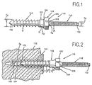
- Fig. 1 is an enlarged elevational view illustrating a bone screw according to an embodiment of the present invention;
- Fig. 2 is an enlarged view, partly in section, illustrating the bone screw in Fig. 1 partially threaded into a vertebra;
- Fig. 3 is a view, similar to Fig. 2, illustrating the bone screw attaching a connecting member of a corrective device to a vertebra;
- Fig. 4 is an enlarged view of a portion of Fig. 3;
- Fig. 5 is an enlarged cross sectional fragmentary view of the bone screw in Fig. 1, taken approximately along line 11-11 in Fig. 1;
- Fig. 6 is is an enlarged cross sectional fragmentary view of the coarse threaded portion of the bone screw of Fig. 1; and
- Fig. 7 is an enlarged cross sectional fragmentary view of a portion of the bone screw in Fig. 1.
-
- An embodiment of a
bone screw 110 according to the present invention is illustrated in Fig. 1. Thebone screw 110 is for use with a connecting member 120 (Fig. 3) of a corrective device for connecting bone portions together. Thebone screw 110 is threaded into abone portion 122 to connect the connectingmember 120 with the bone portion. The bone portions may be parts of a fractured bone or may be different bones of a group of bones, such as vertebrae of a spinal column. - The
bone screw 110 is made from a material compatible with human tissue, such as surgical grade stainless steel or titanium. Thebone screw 110 includes an elongate cylindrical shank 132 (Fig. 5) having a longitudinal central axis B. Thebone screw 110 has an externally threadedportion 142 integrally formed on theshank 132 and extending longitudinally along a portion of the shank. The threadedportion 142 receives a standard internally threaded nut 146 (Fig. 3) to secure the connectingmember 120 to thebone screw 110. - The
bone screw 110 also has another externally threadedportion 144 integrally formed on theshank 132 and extending longitudinally along another portion of the shank. The threadedportion 144 is for connecting thebone screw 110 to acancellous bone portion 122, such as a vertebra, as illustrated in Figs. 2-4. - The configuration of the coarse threaded
portion 144 is illustrated in detail in Figs. 6 and 7 The coarse threadedportion 144 has a leadingface 46 and a trailingface 48 relative to the direction thebone screw 110 advances into thebone portion 122 to the left as viewed in Figs. 6 and 7. The leadingface 46 faces forward in a direction away from the standard threadedportion 142 and is angled to the rear of the bone screw between 40° and 50°. Preferably, the leadingface 46 is disposed at a 45° angle relative to aline 52 normal to the longitudinal central axis A, or 45 degrees relative to the longitudinal central axis. The trailingface 48 faces toward the standard threaded portion and is angled to the rear of the bone screw 10 between 5° and 15°. Preferably, the trailingface 48 is disposed at a 10° angle relative to theline 52 normal to the longitudinal central axis A, or 80 degrees relative to the longitudinal central axis. - An
arcuate root portion 54 having a radius R (Fig. 7) is formed between thefaces face 46 and trailingface 48 of the same thread convolution intersect to form acrest 56. The trailingface 48 slopes rearwardly and radially outwardly from thearcuate root portion 54 to thecrest 56. Thecrest 56 is offset rearwardly from the forwardmost portion 48a of the trailingface 48 by a distance Q which is less than the radius R of curvature of thearcuate root portion 54 to form a rearwardly facingrecess 58. - The
recess 58 is formed between thecrest 56 and thearcuate root portion 54. A portion of the cancellous bone extends into therecess 58 and is trapped by the recess. If a force attempts to move the bone screw axially to the right, as viewed in Fig. 7, thecrests 56 are impaled in the cancellous bone and the portion of the cancellous bone trapped in therecess 58 must be forced rearwardly and radially outwardly of the recess before the bone screw may move to the right. - A relatively
wide opening 59 is formed between thecrests 56 of adjacent thread convolutions of the coarse threadedportion 144. A portion of the cancellous bone in which the bone screw is used projects into the relativelywide opening 59 betweencrests 56 of adjacent threads on opposite sides of a radial plane P. The plane P extends through a center of curvature C of thearcuate root portion 54 and perpendicular to the longitudinal central axis A of the bone screw and does not intersect any portion of a thread convolution of the coarse threadedportion 144. The thread configuration of the threadedportion 144 allows a relatively thick portion of the cancellous bone to extend into the relativelywide opening 59 between theadjacent crests 56. Thus, a relatively strong portion of the cancellous bone forms a solid mounting for the bone screw in the bone. - A line L extending perpendicular to the leading
face 46 of one of the thread convolutions of the coarse threadedportion 144 and extending through thecrest 56 of the next forward adjacent thread convolution is disposed radially outwardly from the center of curvature C of anarcuate root portion 54. The distance that the line L extends radially outwardly of the center of curvature C of thearcuate root portion 54 is less than the radius R of the arcuate root portion. Thus, a cross section of any of the thread convolutions of the coarse threadedportion 144, taken in a radial plane containing the longitudinal central axis A is relatively thick and, therefore, relatively strong and relatively more resistant to breakage than heretofore known screws with rearwardly angled trailing faces. - In one embodiment, the coarse threaded
portion 144 has a crest diameter of approximately 6.5mm and a pitch of 10 threads per 2.5cm extending for approximately 31mm along theshanks 132. The standard threadedportion 142 is a 10-32 NF-2 thread of ca.4.75mm diameter extending for approximately 31mm along theshank 132. Thedrive portion 162 has a hexagonal head configuration for gripping with a suitable tool (not shown). The width across the corners of the drivingportion 162 is slightly smaller than the root diameter of the standard threadedportion 142 to allow thenut 146 pass over the driving portion. - The thread of the threaded
portion 144 has a crest diameter D₂ (Fig. 1) which is larger than the crest diameter D₅ of the thread of the threadedportion 142. The threadedportion 144 has a taperedend portion 152 which pilots thebone screw 110 in an opening 154 (Fig. 3) formed in thebone portion 122. Theopening 154 is defined by a surface having a diameter D₆ (Fig. 2) and preferably has athread 156 tapped in the opening prior to threading thebone screw 110 into thebone portion 122. The tappedthread 156 preferably has the same configuration as the threadedportion 144 of thebone screw 110. The crest diameter D₂ of the threadedportion 144 preferably is at least as large as the diameter D₆ (Fig. 2) of theopening 154. - The last three
thread convolutions portion 144 are formed so the radii Ra, Rb, Rc, respectively, of the root of each thread convolution increases as the thread progresses toward the the right, as illustrated in Fig. 5. The root radii Ra, Rb, Rc of the last threethread convolutions 144a, 144b 144c are greater than the root radius Rr of the other threads on the threadedportion 144. The radii Ra, Rb, Rc of the roots of thethread convolutions bone screw 110 with additional strength in the area of the last threethread convolutions bone screw 110 from the connectingmember 120 tending to bend the bone screw in the area of the last threethread convolutions - The
bone screw 110 also has a drive portion 162 (Fig. 3) for engagement with a suitable tool (not shown), such as a wrench. Thedrive portion 162 is located at an axial end portion of thebone screw 110 adjacent the first threadedportion 142. When a force is applied through the tool to thedrive portion 162 to rotate thebone screw 110 about its longitudinal central axis B (Fig. 5), the threadedportion 144 advances or threads into the tappedthread 156 in the opening 154 (Fig. 2) in thebone portion 122. As described above, the interaction of thecrests 172 and trailingface 176 of the threadedportion 144 with the cancellous tissue of thebone portion 122 prevents thebone screw 110 from being removed from the bone portion by forces acting to move the bone screw axially to the right, as viewed in Fig. 3, relative to the bone portion. - The
bone screw 110 includes a cylindrical body portion 182 (Fig. 1) located between the threadedportions cylindrical body portion 182 is defined by a surface having a diameter D₁ which is substantially equal to the crest diameter D₂ of the threadedportion 144 and, thus, is larger than the diameter D₆ (Fig. 2) of theopening 154. The axial extent Y (Fig. 2) or length of thebody portion 182 is preferably less than the pitch X of the threadedportion 144. When thebone screw 110 is advanced into thebone portion 122, from the position illustrated in Fig. 2 to the position illustrated in Fig. 3, thebody portion 182 engages a portion of thebone portion 122 surrounding theopening 154. - As the
bone screw 110 advances in theopening 154 to the position illustrated in Fig. 3, thebody portion 182 forces a portion of the cancellous bone tissue of thebone portion 122 adjacent the tappedthread 156 forward and radially outward into the tapped thread so no radial clearance exists between the body portion and the surface of the opening. The axial extent Y of thebody portion 182 is shorter than the pitch X of the threadedportion 144, and thus is shorter than the pitch of the tappedthread 156, to assure that a minimum amount of deformation of thebone portion 122 occurs adjacent theopening 154. If too much deformation of thebone portion 122 is caused by thebone screw 110, damage to the bone portion could result. - The
body portion 182, thus, is in circumferential engagement with the surface defining theopening 154 in thebone portion 122. Thebody portion 182 restricts thebone screw 110 from moving relative to thebone portion 122 in a direction transversely to the longitudinal central axis B of the bone screw. Thebody portion 182 also seals or restricts the flow of body fluids from theopening 154 to the areas of the bone screw outside thebone portion 122 which are normally subjected to the highest stress. - An
alternate drive portion 192 having a hex head configuration is formed on theshank 132 between the threadedportion 142 and thebody portion 182. Thedrive portion 192 is engageable by a suitable tool to prevent the rotation of thebone screw 110 during tightening of thenut 146 on the threadedportion 142. Thedrive portion 192 may also be used to remove thebone screw 110 after the connectingmember 120 is removed from a patient, as is typically done in the case of a relatively young patient who has recovered from the injury or damage that the connecting member was used to correct. - A shoulder portion 184 (Fig. 1) is disposed adjacent the
body portion 182 between thealternate drive portion 192 and thebody portion 182. Theshoulder portion 184 acts to eliminate any stress risers which could result from a stepped transition between thebody portion 182 and thealternate drive portion 192. Theshoulder portion 184 is defined by a circular and axially tapered surface. The tapered surface of theshoulder portion 184 has a diameter D₃ which increases as the tapered surface extends in a direction from thebody portion 182 toward thealternate drive portion 192. The diameter D₃ of the tapered surface of theshoulder portion 184 is greater than the diameter D₁ of thebody portion 182. - As the
bone screw 110 is advanced into theopening 154 in thebone portion 122, the tapered surface of theshoulder portion 184 engages thecircumferential edge 180 at the end of theopening 154 to further aid in preventing movement or "wobble" of the bone screw relative to the bone portion. Since thebody portion 182 engages a circumferential portion of a portion of the surface defining theopening 154 and theshoulder portion 184 engages thecircumferential edge 180 of theopening 154, a seal is created between the part of thebone screw 110 extending from theopening 154 and thebone portion 122. The sealing action of thebody portion 182 andshoulder portion 184 restricts the flow of body fluids from theopening 154 in thebone portion 122. Thus, the flow of corrosive body fluids from theopening 154 in thebone portion 122 is further blocked to prevent corrosion to thebone screw 110 in the areas of highest stress, which are typically located between the threadedportions - The
shoulder portion 184 also provides abone screw 110 with a relatively shorter moment arm between its rightmost engagement point with theedge 180 of thebone portion 122, as viewed in Fig. 9, and the connectingmember 120 than if no shoulder portion was present. If no shoulder portion was present, the rightmost engagement point of the bone screw and bone portion, about which the bone screw tends to bend, would be inside the bone portion. The relatively shorter moment arm reduces the torque (from the equation torque = force X moment arm) and, thus, the stress in thebone screw 110 resulting from the force transmitted from the connectingmember 120 tending to bend the bone screw about theedge 180 of thebone portion 122. - A relatively
strong bone screw 110 is provided since theshoulder portion 184 has a relatively large cross-section, taken perpendicularly to the longitudinal central axis B at theengagement point 180, to distribute the force over a relatively large area tending to bend the bone screw about theedge 180. Theshoulder portion 184 also forms a reference surface integrally formed on thebone screw 110. The reference surface enables the surgeon to know how far the threadedportion 144 extends into thebone portion 122 since the length that the threaded portion extends from theshoulder portion 184 is known before threading thebone screw 110 into the bone portion. - A
seat portion 194 has a planar surface integrally formed at an axial end of thealternate drive portion 192 adjacent the threadedportion 142. Theseat portion 194 engages the connectingmember 120 to establish the axial location of the connecting member along thebone screw 110 and to space the connecting member from thebone portion 122. Forming theseat portion 194 integrally on thebone screw 110 assures that the surface engaged by the connectingmember 120 will not loosen and move relative to the bone screw after the surgical procedure so the location of the connectingmember 120 along the bone screw does not change. - Another
shoulder portion 202 extends between theseat portion 194 and the threadedportion 142. Theshoulder portion 202 eliminates any stress risers which could result from a stepped transition between theseat portion 194 and the threadedportion 142. Theshoulder portion 202 is defined by a circular and axially tapered surface. The tapered surface of theshoulder portion 202 has a diameter D₄ that increases as the shoulder portion extends from the threadedportion 142 to theseat portion 194. The diameter D₄ of the tapered surface defining theshoulder portion 202 is greater than the crest diameter D₅ of the threadedportion 142. The increasing diameter D₄ of theshoulder portion 202, thus, provides a relatively large cross-sectional area, taken perpendicular to the longitudinal central axis B, over which to distribute the forces to reduce the stress and provide abone screw 110 less prone to failure. - If the connecting
member 120 is bent to conform to a desired curvature, as illustrated in Figs. 3 and 4, a space may result between theseat portion 194 and the connecting member. If thenut 146 is tightened against the connectingmember 120, stress may concentrate in the portion of thebone screw 110 adjacent theseat portion 194 by the threadedportion 142 attempting to bend or pivot relative the threadedportion 144. To avoid this relative bending, awasher 204 having an angled or wedge-shaped configuration is preferably used between theseat portion 194 and the connectingmember 120. The configuration or angle of thewasher 204 is chosen to closely match the angle of the space between the connectingmember 120 and theseat portion 194. The connectingmember 120 will contact the entireangled surface 206 of thewasher 204 and evenly distribute load over the surface area of theseat portion 194 so the threadedportion 142 does not tend to bend relative to the threadedportion 144.
Claims (17)
- A bone screw (110) for connecting a bone portion (122) with a bone connecting member (120), said bone screw (110) comprising:
an enlongated shank having a longitudinal central axis (B), a first externally threaded portion (142) for receiving an internally threaded nut (146) and a second externally threaded portion (144) for threaded engagement with a surface defining an opening (154) in the bone portion (122) to attach the bone screw (110) to the bone portion (122), whereby the bone screw (110) comprises an unthreaded portion (182, 184) integral with said shank, whereby said unthreaded portion (182, 184) is defined by a shoulder portion with a circular and continuously merging axially tapered surface located intermediate said first externally threaded portion (142) and said second externally threaded portion (144) for projecting into the opening (154) and for engaging a portion of the surface defining the opening in the bone portion (122) to restrict movement of said bone screw (110) relative to the bone portion (122) in a direction transverse to the longitudinal central axis (B) of said shank and to block effluence from the opening (154) in the bone portion (122), said shoulder portion having a tapering in cross-section from a smaller cross-section to a larger cross-section as said shoulder portion extends from said second externally threaded portion toward said first externally threaded portion. - The bone screw (110) set forth in claim 1 wherein said bone screw (110) further includes a longitudinally extending cylindrical body portion (182) having a diameter (D1) substantially equal to the crest diameter (D2) of the thread on said second externally threaded portion (144), said shoulder portion (184) being located between said first externally threaded portion (142) and said body portion (182), said shoulder portion (184) having a circular tapering surface with a diameter (D3) which increases as said shoulder portion (184) extends from said body portion (182) toward said first externally threaded portion (142), the diameter (D3) of the circular tapering surface defining said shoulder portion (184) being greater than the diameter (D1) defining said body portion (182), said body portion (182) having a longitudinal extent which is less than the pitch of the thread of said second externally threaded portion (144).
- The bone screw (110) set forth in claim 1 further including a first driving portion (162) for transmitting a force to said shank to rotate said shank about its longitudinal central axis (B) for threading said second externally threaded portion (144) in the opening (154) in the bone portion (122) upon the application of the force to said driving portion (162), said first driving portion (162) being disposed at an axial end portion of said bone screw (110) which is trimmed away after said second externally threaded portion (144) is threaded into the opening in the bone portion (122), a second driving portion (192) located between said first (142) and second (144) externally threaded portions for rotating said shank about its longitudinal central axis to remove said second externally threaded portion (144) from the bone portion (122) after the first driving portion (162) has been trimmed away.
- The bone screw (110) set forth in claim 2 wherein said second externally threaded portion (144) further includes at least one thread (144c) located adjacent said body portion (182) having a root diameter greater than the root diameter of other threads (144a, 144b) on said second externally threaded portion (144).
- The bone screw (110) set forth in claim 1 wherein said second externally threaded portion (144) has a thread with a crest diameter (D2) greater than the crest diameter (D5) of a thread on said first externally threaded portion (142).
- The bone screw (110) as set forth in claim 1 wherein said bone screw (110) comprises a seat portion (194) on said shank having a surface for engaging the bone connecting member (120) to establish the axial location of said bone connecting member (120) along said bone screw (110).
- A bone screw (110) as set forth in claim 2 wherein said bone screw (110) comprises a second shoulder portion (202) located intermediate said body portion (182) and said first externally threaded portion (142) and having a circular tapering surface which increases in diameter (D4) as said second shoulder portion (202) extends from said first threaded portion (142) toward said body portion (182), the diameter (D4) of the circular tapering surface defining said second shoulder portion (202) being greater than the root diameter of the thread on said first threaded portion (142).
- A bone screw (110) as set forth in claim 6 wherein a shoulder portion (202) is located intermediate said seat portion (194) and said first externally threaded portion (142) and having a circular tapering surface which increases in diameter (D4) as said shoulder portion (202) extends from said first threaded portion (142) toward said seat portion (194), the diameter (D4) of the circular tapering surface defining said shoulder portion (202) being greater than the root diameter of the thread on said first threaded portion (142).
- A bone screw (110) as set forth in claim 1 wherein:
a second driving portion (192) is integral with said shank and is located intermediate said first externally threaded portion (142) and said second externally threaded portion (144);
said second driving portion having a transverse cross-section greater than the transverse cross-section of each of said first externally threaded portion (142) and said second externally threaded portion (144); and
said shoulder portion (184) integral with said shank is located intermediate said second externally threaded portion (144) and said second driving portion (192);
said shoulder portion (184) being unthreaded and tapering in cross-section from a larger cross-section adjacent said second driving portion (192) to a smaller cross-section adjacent said second externally threaded portion;
said shoulder portion (184) having a transverse cross-section greater than the transverse cross-section of the opening (154) in the bone portion (122), for projecting into the opening (154) and for engaging a portion of the surface defining the opening (154) in the bone portion (122) to restrict movement of said bone screw (110) relative to the bone portion (122) in a direction transverse to the longitudinal central axis (B) of said shank and to block effluence from the opening (154) in the bone portion (122). - A bone screw (110) as set forth in claim 9, comprising a seat portion (194, 202) integral with said shank and located intermediate said first externally threaded portion (142) and said second driving portion (192), said seat portion (194, 202) being unthreaded and tapering in cross-section from a larger cross-section adjacent said second driving portion (192) to a smaller cross-section adjacent said first externally threaded portion (142).
- A bone screw (110) as set forth in claim 1 wherein said second externally threaded portion (144, 14) includes a thread convolution having a root portion (54), a crest portion (56), a leading flank surface (46) extending between said root (54) and crest portions (56) and facing forwardly in a direction away from said first externally threaded portion (142) and a trailing flank surface (48) extending between said crest (56) and root (54) portions and facing rearwardly in a direction towards said first externally threaded portion (142), said root portion (54) having an arcuate cross sectional configuration in a radial plane containing the longitudinal central axis (B) of said bone screw (110), said trailing flank surface (48) sloping rearwardly and outwardly from said root portion (54) to said crest portion (56), said crest portion (56) being offset rearwardly of the forwardmost portion of said trailing flank surface (48) by a distance (Q) which is less than the radius of curvature (R) of the arcuate root portion (54) to form a rearwardly facing recess (58) between said crest (56) and root (54) portions and to form a wide space (59) between adjacent turns of said crest portion (56) of said thread convolution of said second externally threaded portion (144) through which bone may project radially inwardly into the space (59) between adjacent turns on opposite sides of a radial plane extending through the center of curvature (C) of said root portion (54) and perpendicular to the longitudinal central axis (B) of said bone screw (110) to form a solid mounting for said bone screw (110) in the bone.
- A bone screw (110) as set forth in claim 11 wherein a line (L) extending perpendicular to the leading flank (46) of one turn of the thread convolution and extending through the crest (56) of the next forward turn of the thread convolution is disposed radially outwardly from the center of curvature (C) of the arcuate root portion (54) of the thread convolution by a distance which is less than the radius of curvature (R) of the arcuate root (54) of the thread convolution.
- The bone screw (110) set forth in claim 11 wherein said leading flank surface (46) extends at an angle of between 40° and 50° relative to the longitudinal central axis (B) of said bone screw (110) and said trailing flank surface (48) extends at an angle of between 75° and 85° relative to the longitudinal central axis (B) of said bone screw (110).
- The bone screw (110) set forth in claim 9 wherein said second externally threaded portion (144) further includes at least one thread (144c) located adjacent said shoulder portion (184) having a root diameter greater than the root diameter of other threads (144a, 144b) on said second externally threaded portion (144).
- The bone screw (110) as set forth in claim 1 wherein said second externally threaded portion (144) has a plurality of thread convolutions with equal crest diameters (D2).
- The bone screw (110) as set forth in claim 15 wherein said second externally threaded portion (144) has a plurality of thread convolutions along the entire length of said second externally threaded end portion (144), all of the thread convolutions of said plurality of thread convolutions having the same crest diameter (D2).
- The bone screw (110), as set forth in claim 1 and claim 16 further including a seat portion (194) having a surface for engaging the bone connecting member (120) and located between said shoulder portion (184) and said first externally threaded portion (142), said shoulder portion (184) extending from said seat portion (194) toward said second externally threaded portion (144).
Applications Claiming Priority (2)
| Application Number | Priority Date | Filing Date | Title |
|---|---|---|---|
| US146739 | 1988-01-21 | ||
| US07/146,739 US4854311A (en) | 1986-01-09 | 1988-01-21 | Bone screw |
Publications (2)
| Publication Number | Publication Date |
|---|---|
| EP0325682A1 EP0325682A1 (en) | 1989-08-02 |
| EP0325682B1 true EP0325682B1 (en) | 1993-11-18 |
Family
ID=22518788
Family Applications (1)
| Application Number | Title | Priority Date | Filing Date |
|---|---|---|---|
| EP88109604A Expired - Lifetime EP0325682B1 (en) | 1988-01-21 | 1988-06-16 | Bone screw |
Country Status (6)
| Country | Link |
|---|---|
| US (1) | US4854311A (en) |
| EP (1) | EP0325682B1 (en) |
| JP (1) | JPH01192345A (en) |
| CA (1) | CA1294501C (en) |
| DE (2) | DE3885731T2 (en) |
| ES (1) | ES2023085T3 (en) |
Families Citing this family (155)
| Publication number | Priority date | Publication date | Assignee | Title |
|---|---|---|---|---|
| JPH066810Y2 (en) * | 1989-11-29 | 1994-02-23 | 旭光学工業株式会社 | Vertebral body fixation plate |
| DE3942326A1 (en) * | 1989-12-21 | 1991-06-27 | Haerle Anton | SCREW AS AN OSTEOSYNTHESIS TOOL |
| DE4010977C1 (en) * | 1990-04-05 | 1991-11-14 | Aesculap Ag, 7200 Tuttlingen, De | |
| JPH04138152A (en) * | 1990-09-29 | 1992-05-12 | Ikufumi Yamada | Internal fixing tool for collum humeri fracture |
| US5113685A (en) * | 1991-01-28 | 1992-05-19 | Acromed Corporation | Apparatus for contouring spine plates and/or rods |
| US5222954A (en) * | 1991-06-21 | 1993-06-29 | Artifex, Ltd. | Spinal implant system and method for installing the implant |
| DE4136178A1 (en) * | 1991-11-02 | 1993-05-06 | Deutsche Thomson-Brandt Gmbh, 7730 Villingen-Schwenningen, De | CIRCUIT FOR CONTINUOUS ZOOM ADJUSTMENT OF PICTURE WIDTH IN A TELEVISION RECEIVER |
| US5282862A (en) * | 1991-12-03 | 1994-02-01 | Artifex Ltd. | Spinal implant system and a method for installing the implant onto a vertebral column |
| JPH07501845A (en) * | 1991-12-13 | 1995-02-23 | エクソン・ケミカル・パテンツ・インク | Copolymers of ethylene and longer alpha olefins |
| US5171279A (en) * | 1992-03-17 | 1992-12-15 | Danek Medical | Method for subcutaneous suprafascial pedicular internal fixation |
| US6299615B1 (en) | 1993-01-21 | 2001-10-09 | Acumed, Inc. | System for fusing joints |
| US6984235B2 (en) * | 1993-01-21 | 2006-01-10 | Acumed Llc | System for fusing joints |
| US8070786B2 (en) | 1993-01-21 | 2011-12-06 | Acumed Llc | System for fusing joints |
| US5871486A (en) * | 1993-01-21 | 1999-02-16 | Acumed, Inc. | Variable pitch bone screw |
| US6030162A (en) * | 1998-12-18 | 2000-02-29 | Acumed, Inc. | Axial tension screw |
| US5964768A (en) * | 1993-01-21 | 1999-10-12 | Acumed, Inc. | Tapered bone screw with continuously varying pitch |
| US9161793B2 (en) | 1993-01-21 | 2015-10-20 | Acumed Llc | Axial tension screw |
| DE4307633C1 (en) * | 1993-03-11 | 1994-05-19 | Pennig Dietmar | Screw for locking marrow-cavity pin in position - has threaded section of shank near head and opposite thread on head with unthreaded section of shank between |
| US5476463A (en) * | 1994-01-12 | 1995-12-19 | Acromed Corporation | Spinal column retaining apparatus |
| US5443564A (en) * | 1994-04-14 | 1995-08-22 | Reaves; Donald G. | Tie rod loosening tool for use with a tie rod assembly |
| US5556687A (en) | 1994-10-14 | 1996-09-17 | Acromed Corporation | Composite structure suitable for use as a bone plate and method for making said structure |
| US6176861B1 (en) | 1994-10-25 | 2001-01-23 | Sdgi Holdings, Inc. | Modular spinal system |
| US6004322A (en) * | 1994-10-25 | 1999-12-21 | Sdgi Holdings, Inc. | Modular pedicle screw system |
| US5613967A (en) | 1995-04-28 | 1997-03-25 | Acromed Corporation | Apparatus for maintaining bone portions in a desired spatial relationship |
| US5728127A (en) * | 1995-06-27 | 1998-03-17 | Acro Med Corporation | Apparatus for maintaining vertebrae of a spinal column in a desired spatial relationship |
| US6146384A (en) * | 1995-10-13 | 2000-11-14 | Sdgi Holdings, Inc. | Orthopedic fixation device and method of implantation |
| US5688275A (en) * | 1996-02-09 | 1997-11-18 | Koros; Tibor | Spinal column rod fixation system |
| DE19608859A1 (en) * | 1996-03-07 | 1997-09-11 | Hilti Ag | Anchor rod for composite anchors |
| US5899902A (en) * | 1997-07-03 | 1999-05-04 | Depuy Motech Acromed Corporation | Fastener |
| EP0888754A1 (en) | 1997-07-03 | 1999-01-07 | Acromed Corporation | Osteosynthetic Fastener |
| WO1999011177A2 (en) * | 1997-09-05 | 1999-03-11 | Deslauriers Richard J | Self-retaining anchor track and method of making and using same |
| US5891146A (en) * | 1997-10-15 | 1999-04-06 | Applied Biological Concepts, Inc. | Wedge orthopedic screw |
| SE9802571D0 (en) * | 1998-07-17 | 1998-07-17 | Astra Ab | Implant |
| US6302883B1 (en) | 1998-10-22 | 2001-10-16 | Depuy Acromed, Inc. | Bone plate-ratcheting compression apparatus |
| US6341917B1 (en) * | 1998-12-30 | 2002-01-29 | Emhart Inc. | Double ended stud fastening system |
| DE19912364B4 (en) * | 1999-03-19 | 2004-10-07 | Peter Brehm | pedicle screw |
| US6315779B1 (en) * | 1999-04-16 | 2001-11-13 | Sdgi Holdings, Inc. | Multi-axial bone anchor system |
| US6248107B1 (en) | 2000-03-15 | 2001-06-19 | Sdgi Holdings, Inc. | System for reducing the displacement of a vertebra |
| US6468277B1 (en) * | 2000-04-04 | 2002-10-22 | Ethicon, Inc. | Orthopedic screw and method |
| EP1284707A4 (en) | 2000-05-30 | 2003-06-25 | Paul S Lin | Implant for placement between cervical vertebrae |
| US6468309B1 (en) | 2000-10-05 | 2002-10-22 | Cleveland Clinic Foundation | Method and apparatus for stabilizing adjacent bones |
| US6953462B2 (en) * | 2000-10-05 | 2005-10-11 | The Cleveland Clinic Foundation | Apparatus for implantation into bone |
| US6551322B1 (en) | 2000-10-05 | 2003-04-22 | The Cleveland Clinic Foundation | Apparatus for implantation into bone |
| US6551319B2 (en) | 2000-11-08 | 2003-04-22 | The Cleveland Clinic Foundation | Apparatus for implantation into bone |
| US6527774B2 (en) | 2000-11-08 | 2003-03-04 | The Cleveland Clinic Foundation | Apparatus for attaching fractured sections of bone |
| US6488683B2 (en) | 2000-11-08 | 2002-12-03 | Cleveland Clinic Foundation | Method and apparatus for correcting spinal deformity |
| US6551320B2 (en) | 2000-11-08 | 2003-04-22 | The Cleveland Clinic Foundation | Method and apparatus for correcting spinal deformity |
| US6544265B2 (en) | 2000-11-08 | 2003-04-08 | The Cleveland Clinic Foundation | Apparatus for implantation into bone related applications |
| RS49794B (en) * | 2000-11-22 | 2008-06-05 | Milorad Mitković | Internal fixator of bones |
| US20030215564A1 (en) * | 2001-01-18 | 2003-11-20 | Heller Phillip F. | Method and apparatus for coating an endoprosthesis |
| US6530731B2 (en) * | 2001-02-01 | 2003-03-11 | General Dynamics Land Systems, Inc. | Self-tapping insert, insert assembly, and method for mounting the insert |
| US6666638B2 (en) * | 2001-02-15 | 2003-12-23 | Phillips Screw Company | Deck screw having multiple threaded sections |
| US7235079B2 (en) | 2004-11-18 | 2007-06-26 | Acumed Llc | Composite bone fasteners |
| US6770075B2 (en) | 2001-05-17 | 2004-08-03 | Robert S. Howland | Spinal fixation apparatus with enhanced axial support and methods for use |
| US6478798B1 (en) | 2001-05-17 | 2002-11-12 | Robert S. Howland | Spinal fixation apparatus and methods for use |
| US7314467B2 (en) | 2002-04-24 | 2008-01-01 | Medical Device Advisory Development Group, Llc. | Multi selective axis spinal fixation system |
| US6966737B2 (en) * | 2001-08-06 | 2005-11-22 | Olympic Manufacturing Group, Inc. | Deck screws suitable for use with composite lumber |
| US6827538B2 (en) * | 2001-09-10 | 2004-12-07 | Htg-Wyandotte, Llc | Torque prevailing stud |
| US6899714B2 (en) * | 2001-10-03 | 2005-05-31 | Vaughan Medical Technologies, Inc. | Vertebral stabilization assembly and method |
| KR20030037616A (en) * | 2001-11-07 | 2003-05-14 | 주식회사 코렌텍 | Free length hip pin |
| US7322983B2 (en) * | 2002-02-12 | 2008-01-29 | Ebi, L.P. | Self-locking bone screw and implant |
| US6758512B2 (en) * | 2002-08-01 | 2004-07-06 | Alan Dobbs | Window frame stud |
| EP1420298B1 (en) | 2002-11-12 | 2013-02-20 | ASML Netherlands B.V. | Lithographic apparatus |
| US7641677B2 (en) * | 2002-11-20 | 2010-01-05 | Orthopediatrics Corp. | Compression bone fragment wire |
| US7517350B2 (en) * | 2002-11-20 | 2009-04-14 | Orthopediatrics Corp. | Convertible threaded compression device and method of use |
| US7141051B2 (en) | 2003-02-05 | 2006-11-28 | Pioneer Laboratories, Inc. | Low profile spinal fixation system |
| US20040228705A1 (en) | 2003-05-16 | 2004-11-18 | Abbott-Interfast Corporation. | Fasteners for composite material |
| FR2856579B1 (en) * | 2003-06-27 | 2006-03-17 | Medicrea | VERTEBRAL OSTEOSYNTHESIS EQUIPMENT AND METHOD FOR MANUFACTURING BONE ANCHORING MEMBER INCLUDING THESE MATERIALS |
| US7316714B2 (en) * | 2003-08-05 | 2008-01-08 | Flexuspine, Inc. | Artificial functional spinal unit assemblies |
| US7753958B2 (en) * | 2003-08-05 | 2010-07-13 | Gordon Charles R | Expandable intervertebral implant |
| US7909869B2 (en) * | 2003-08-05 | 2011-03-22 | Flexuspine, Inc. | Artificial spinal unit assemblies |
| US7204853B2 (en) * | 2003-08-05 | 2007-04-17 | Flexuspine, Inc. | Artificial functional spinal unit assemblies |
| US20060229729A1 (en) * | 2003-08-05 | 2006-10-12 | Gordon Charles R | Expandable intervertebral implant for use with instrument |
| US7785351B2 (en) | 2003-08-05 | 2010-08-31 | Flexuspine, Inc. | Artificial functional spinal implant unit system and method for use |
| US7503924B2 (en) | 2004-04-08 | 2009-03-17 | Globus Medical, Inc. | Polyaxial screw |
| US8475495B2 (en) | 2004-04-08 | 2013-07-02 | Globus Medical | Polyaxial screw |
| US8114158B2 (en) | 2004-08-03 | 2012-02-14 | Kspine, Inc. | Facet device and method |
| US7854752B2 (en) | 2004-08-09 | 2010-12-21 | Theken Spine, Llc | System and method for dynamic skeletal stabilization |
| US20060095037A1 (en) * | 2004-10-29 | 2006-05-04 | Jones Bryan S | Connector assemblies for connecting a bone anchor to a fixation element |
| EP1814463A4 (en) * | 2004-11-15 | 2013-10-02 | Scandius Biomedical Inc | Method and apparatus for the repair of a rotator cuff (rtc) tendon or ligament |
| US8740955B2 (en) | 2005-02-15 | 2014-06-03 | Zimmer, Inc. | Bone screw with multiple thread profiles for far cortical locking and flexible engagement to a bone |
| US7338491B2 (en) * | 2005-03-22 | 2008-03-04 | Spinefrontier Inc | Spinal fixation locking mechanism |
| US7811310B2 (en) * | 2005-05-04 | 2010-10-12 | Spinefrontier, Inc | Multistage spinal fixation locking mechanism |
| DE102005054461B4 (en) * | 2005-11-15 | 2010-10-14 | Daimler Ag | Device for the pivotable connection of at least two components and method for mounting the device |
| US20070162017A1 (en) * | 2005-11-28 | 2007-07-12 | Gambale Michael A | Method and apparatus for treatment of bones |
| US7255523B2 (en) * | 2005-12-22 | 2007-08-14 | Prime Source Building Products, Inc. | Dual threaded screw for composite materials |
| US8740947B2 (en) * | 2006-02-15 | 2014-06-03 | Warsaw, Orthopedic, Inc. | Multiple lead bone fixation apparatus |
| US8118869B2 (en) | 2006-03-08 | 2012-02-21 | Flexuspine, Inc. | Dynamic interbody device |
| US8025681B2 (en) | 2006-03-29 | 2011-09-27 | Theken Spine, Llc | Dynamic motion spinal stabilization system |
| US20070288012A1 (en) * | 2006-04-21 | 2007-12-13 | Dennis Colleran | Dynamic motion spinal stabilization system and device |
| US8894661B2 (en) * | 2007-08-16 | 2014-11-25 | Smith & Nephew, Inc. | Helicoil interference fixation system for attaching a graft ligament to a bone |
| US20080154314A1 (en) * | 2006-08-16 | 2008-06-26 | Mcdevitt Dennis M | Composite interference screw for attaching a graft ligament to a bone, and other apparatus for making attachments to bone |
| US7959677B2 (en) * | 2007-01-19 | 2011-06-14 | Flexuspine, Inc. | Artificial functional spinal unit system and method for use |
| EP2175791A4 (en) * | 2007-03-23 | 2013-05-15 | Zbigniew Matulaniec | Bone screw apparatus and related methods of use |
| CA2689965A1 (en) | 2007-06-06 | 2008-12-18 | Kspine, Inc. | Medical device and method to correct deformity |
| US9095391B2 (en) * | 2007-06-11 | 2015-08-04 | Aeolin Llc | Osseointegration and biointegration coatings for bone screw implants |
| US8668725B2 (en) * | 2007-07-13 | 2014-03-11 | Southern Spine, Llc | Bone screw |
| US20090018592A1 (en) * | 2007-07-13 | 2009-01-15 | Pitbladdo Richard B | Bone screw for orthopedic apparatus |
| US8197511B2 (en) | 2007-09-24 | 2012-06-12 | Miller M Todd | Suture anchor having a suture engaging structure and inserter arrangement |
| US8632568B2 (en) * | 2007-09-24 | 2014-01-21 | Stryker Corporation | Suture anchor having a suture engaging structure and inserter arrangement |
| US20090105767A1 (en) * | 2007-10-18 | 2009-04-23 | Inbone Technologies, Inc. | Total joint subsidence protector |
| US20090105840A1 (en) * | 2007-10-18 | 2009-04-23 | Inbone Technologies, Inc. | Fibular stiffener and bony defect replacer |
| US8523912B2 (en) * | 2007-10-22 | 2013-09-03 | Flexuspine, Inc. | Posterior stabilization systems with shared, dual dampener systems |
| US8267965B2 (en) * | 2007-10-22 | 2012-09-18 | Flexuspine, Inc. | Spinal stabilization systems with dynamic interbody devices |
| US8162994B2 (en) * | 2007-10-22 | 2012-04-24 | Flexuspine, Inc. | Posterior stabilization system with isolated, dual dampener systems |
| US8187330B2 (en) * | 2007-10-22 | 2012-05-29 | Flexuspine, Inc. | Dampener system for a posterior stabilization system with a variable length elongated member |
| US8182514B2 (en) * | 2007-10-22 | 2012-05-22 | Flexuspine, Inc. | Dampener system for a posterior stabilization system with a fixed length elongated member |
| US8157844B2 (en) * | 2007-10-22 | 2012-04-17 | Flexuspine, Inc. | Dampener system for a posterior stabilization system with a variable length elongated member |
| US20090125071A1 (en) * | 2007-10-23 | 2009-05-14 | Skinlo David M | Shape-changing anatomical anchor |
| US8821546B2 (en) | 2007-11-06 | 2014-09-02 | Stanus Investments, Inc. | Vertebral screw arrangement with locking pin |
| KR101225940B1 (en) * | 2007-11-21 | 2013-01-24 | 탄탈린 에이/에스 | Object having a ductile and corrosion resistant surface layer |
| US9017329B2 (en) * | 2008-06-24 | 2015-04-28 | Extremity Medical, Llc | Intramedullary fixation assembly and method of use |
| US8828058B2 (en) | 2008-11-11 | 2014-09-09 | Kspine, Inc. | Growth directed vertebral fixation system with distractible connector(s) and apical control |
| KR20110131210A (en) * | 2009-02-16 | 2011-12-06 | 유니스틸 테크놀로지 리미티드 | Self-tapping thread forming screw and corresponding thread roll die |
| US8357182B2 (en) | 2009-03-26 | 2013-01-22 | Kspine, Inc. | Alignment system with longitudinal support features |
| US9566098B2 (en) | 2009-04-23 | 2017-02-14 | University Of Massachusetts | Bone fixture assembly |
| WO2010124230A1 (en) * | 2009-04-23 | 2010-10-28 | University Of Massachusetts | Bone fixture assembly |
| US9168071B2 (en) | 2009-09-15 | 2015-10-27 | K2M, Inc. | Growth modulation system |
| US9011504B2 (en) * | 2009-10-02 | 2015-04-21 | Gary Reed | Apparatus and method for use in the treatment of hammertoe |
| FR2957239B1 (en) * | 2010-03-09 | 2013-06-28 | Synchro Medical | SCREWS FOR BONE REPAIR |
| US9579188B2 (en) | 2010-03-10 | 2017-02-28 | Smith & Nephew, Inc. | Anchor having a controlled driver orientation |
| US9775702B2 (en) | 2010-03-10 | 2017-10-03 | Smith & Nephew, Inc. | Composite interference screws and drivers |
| US9308080B2 (en) | 2010-03-10 | 2016-04-12 | Smith & Nephew Inc. | Composite interference screws and drivers |
| JP5899124B2 (en) | 2010-03-10 | 2016-04-06 | スミス アンド ネフュー インコーポレーテッド | Compound tightening screw and device |
| US8617216B2 (en) | 2010-04-05 | 2013-12-31 | David L. Brumfield | Fully-adjustable bone fixation device |
| SG179322A1 (en) | 2010-10-01 | 2012-04-27 | Infastech Ip Pte Ltd | Threaded fastener |
| WO2012074991A1 (en) | 2010-11-30 | 2012-06-07 | Amit Sinha | Bone compression and fixation devices |
| FR2971413B1 (en) * | 2011-02-15 | 2013-12-27 | Jean-Pierre Py | SCREW FOR MEDICAL USE, PARTICULARLY FOR REALIZING A OSTEOSYNTHESIS |
| CN103841920B (en) | 2011-03-11 | 2016-12-07 | 史密夫和内修有限公司 | Trepan |
| US8388687B2 (en) | 2011-03-25 | 2013-03-05 | Flexuspine, Inc. | Interbody device insertion systems and methods |
| CA2838047A1 (en) | 2011-06-03 | 2012-12-06 | Kspine, Inc. | Spinal correction system actuators |
| AU2012267924B2 (en) | 2011-06-07 | 2016-08-11 | Smith & Nephew, Inc. | Surgical anchor delivery system |
| US9186187B2 (en) | 2011-07-15 | 2015-11-17 | Globus Medical, Inc. | Orthopedic fixation devices and methods of installation thereof |
| US9358047B2 (en) | 2011-07-15 | 2016-06-07 | Globus Medical, Inc. | Orthopedic fixation devices and methods of installation thereof |
| US9198694B2 (en) | 2011-07-15 | 2015-12-01 | Globus Medical, Inc. | Orthopedic fixation devices and methods of installation thereof |
| US8888827B2 (en) | 2011-07-15 | 2014-11-18 | Globus Medical, Inc. | Orthopedic fixation devices and methods of installation thereof |
| US9993269B2 (en) | 2011-07-15 | 2018-06-12 | Globus Medical, Inc. | Orthopedic fixation devices and methods of installation thereof |
| WO2013013218A2 (en) | 2011-07-20 | 2013-01-24 | Horwitz Michael H | Minimal incision removable bone screw, driver, and method of use |
| US9468468B2 (en) | 2011-11-16 | 2016-10-18 | K2M, Inc. | Transverse connector for spinal stabilization system |
| US9468469B2 (en) | 2011-11-16 | 2016-10-18 | K2M, Inc. | Transverse coupler adjuster spinal correction systems and methods |
| US9451987B2 (en) | 2011-11-16 | 2016-09-27 | K2M, Inc. | System and method for spinal correction |
| WO2014172632A2 (en) | 2011-11-16 | 2014-10-23 | Kspine, Inc. | Spinal correction and secondary stabilization |
| US8920472B2 (en) | 2011-11-16 | 2014-12-30 | Kspine, Inc. | Spinal correction and secondary stabilization |
| US9526627B2 (en) | 2011-11-17 | 2016-12-27 | Exactech, Inc. | Expandable interbody device system and method |
| ITTO20120104A1 (en) * | 2012-02-08 | 2013-08-09 | Twocare S R L | DENTAL PLANT OR BONE |
| US8858596B2 (en) | 2012-03-20 | 2014-10-14 | Stryker Corporation | Suture anchor having a suture engaging structure |
| US9492288B2 (en) | 2013-02-20 | 2016-11-15 | Flexuspine, Inc. | Expandable fusion device for positioning between adjacent vertebral bodies |
| US9155531B2 (en) | 2013-03-15 | 2015-10-13 | Smith & Nephew, Inc. | Miniaturized dual drive open architecture suture anchor |
| JP6747969B2 (en) | 2013-04-09 | 2020-08-26 | スミス アンド ネフュー インコーポレーテッドSmith & Nephew,Inc. | Open structure type interference screw |
| US9468471B2 (en) | 2013-09-17 | 2016-10-18 | K2M, Inc. | Transverse coupler adjuster spinal correction systems and methods |
| US9078702B1 (en) * | 2014-03-20 | 2015-07-14 | Amendia, Inc. | Spinal alignment correction system and methods of use |
| US9517144B2 (en) | 2014-04-24 | 2016-12-13 | Exactech, Inc. | Limited profile intervertebral implant with incorporated fastening mechanism |
| US10398565B2 (en) | 2014-04-24 | 2019-09-03 | Choice Spine, Llc | Limited profile intervertebral implant with incorporated fastening and locking mechanism |
| AT517141B1 (en) * | 2015-04-15 | 2019-08-15 | Pastl Klaus | bone screw |
| US20180073547A1 (en) * | 2016-09-13 | 2018-03-15 | Ying-Chin CHAO | Structure of screw |
Citations (1)
| Publication number | Priority date | Publication date | Assignee | Title |
|---|---|---|---|---|
| US4653481A (en) * | 1985-07-24 | 1987-03-31 | Howland Robert S | Advanced spine fixation system and method |
Family Cites Families (21)
| Publication number | Priority date | Publication date | Assignee | Title |
|---|---|---|---|---|
| US272778A (en) * | 1883-02-20 | William schilling | ||
| GB189313867A (en) * | 1893-07-18 | 1893-11-25 | George Augustus Macnutt | An Improved Screw for Woodwork and other purposes. |
| US1801186A (en) * | 1929-04-18 | 1931-04-14 | Internat Screw Co | Single-point, double-thread drive screw |
| US2121193A (en) * | 1932-12-21 | 1938-06-21 | Hanicke Paul Gustav Erich | Fracture clamping apparatus |
| US2570465A (en) * | 1949-08-01 | 1951-10-09 | Joseph S Lundholm | Means for fixation of hip fractures |
| GB913039A (en) * | 1961-10-03 | 1962-12-12 | Down Bros And Meyer & Phelps L | Improvements in and relating to surgical implants |
| US3489143A (en) * | 1967-12-15 | 1970-01-13 | William X Halloran | Convertible hip pin |
| US3660233A (en) * | 1969-11-12 | 1972-05-02 | Gen Electric | Nuclear reactor upper core grid |
| US3693616A (en) * | 1970-06-26 | 1972-09-26 | Robert Roaf | Device for correcting scoliotic curves |
| US3706309A (en) * | 1971-04-29 | 1972-12-19 | Irwing N Toftness | Device for applying and releasing pressure |
| GB1519139A (en) * | 1974-06-18 | 1978-07-26 | Crock H V And Pericic L | L securing elongate members to structurs more especially in surgical procedures |
| GB1565178A (en) * | 1977-02-24 | 1980-04-16 | Interfix Ltd | Bone screw |
| CH651192A5 (en) * | 1980-11-20 | 1985-09-13 | Synthes Ag | OSTEOSYNTHETIC DEVICE AND CORRESPONDING DRILL GAUGE. |
| US4448191A (en) * | 1981-07-07 | 1984-05-15 | Rodnyansky Lazar I | Implantable correctant of a spinal curvature and a method for treatment of a spinal curvature |
| GB2108229B (en) * | 1981-10-16 | 1985-10-30 | Howse And Company Limited D | Bone fixation screws |
| US4456005A (en) * | 1982-09-30 | 1984-06-26 | Lichty Terry K | External compression bone fixation device |
| SU1115738A1 (en) * | 1983-05-10 | 1984-09-30 | Кемеровский государственный медицинский институт | Fixative of femur neck |
| US4611581A (en) * | 1983-12-16 | 1986-09-16 | Acromed Corporation | Apparatus for straightening spinal columns |
| US4612920A (en) * | 1984-11-06 | 1986-09-23 | Zimmer, Inc. | Compression hip screw |
| US4655199A (en) * | 1985-03-29 | 1987-04-07 | Acromed Corporation | Spinal column straightening apparatus |
| DE3538593A1 (en) * | 1985-10-30 | 1987-05-07 | Thomas Dr Med Jungeblod | Device for the surgical treatment of bones, especially of fractured bones |
-
1988
- 1988-01-21 US US07/146,739 patent/US4854311A/en not_active Expired - Lifetime
- 1988-06-10 CA CA000569173A patent/CA1294501C/en not_active Expired - Lifetime
- 1988-06-16 EP EP88109604A patent/EP0325682B1/en not_active Expired - Lifetime
- 1988-06-16 ES ES198888109604T patent/ES2023085T3/en not_active Expired - Lifetime
- 1988-06-16 DE DE88109604T patent/DE3885731T2/en not_active Expired - Lifetime
- 1988-06-16 DE DE198888109604T patent/DE325682T1/en active Pending
- 1988-08-03 JP JP63194316A patent/JPH01192345A/en active Granted
Patent Citations (1)
| Publication number | Priority date | Publication date | Assignee | Title |
|---|---|---|---|---|
| US4653481A (en) * | 1985-07-24 | 1987-03-31 | Howland Robert S | Advanced spine fixation system and method |
Also Published As
| Publication number | Publication date |
|---|---|
| EP0325682A1 (en) | 1989-08-02 |
| US4854311A (en) | 1989-08-08 |
| JPH0567288B2 (en) | 1993-09-24 |
| ES2023085A4 (en) | 1992-01-01 |
| CA1294501C (en) | 1992-01-21 |
| DE3885731T2 (en) | 1994-04-28 |
| DE3885731D1 (en) | 1993-12-23 |
| JPH01192345A (en) | 1989-08-02 |
| DE325682T1 (en) | 1991-09-05 |
| ES2023085T3 (en) | 1994-02-01 |
Similar Documents
| Publication | Publication Date | Title |
|---|---|---|
| EP0325682B1 (en) | Bone screw | |
| CA2165453C (en) | Clamps for spinal fixation systems | |
| AU682839B2 (en) | Pedicular screw and posterior spinal instrumentation | |
| US5814046A (en) | Pedicular screw and posterior spinal instrumentation | |
| US5382248A (en) | System and method for stabilizing bone segments | |
| EP1087711B1 (en) | Device for securing spinal rods | |
| EP1088521B1 (en) | Apparatus for maintaining bone portions in a desired spatial relationship | |
| EP1449486B1 (en) | Implant device including threaded locking profile | |
| US8771322B2 (en) | Cranial flap fixation system and method | |
| KR0179649B1 (en) | Device for straightening securing compressing and elongating the spinal column | |
| EP0874594B1 (en) | Device for linking adjacent rods in spinal instrumentation | |
| US5476463A (en) | Spinal column retaining apparatus | |
| IE922307A1 (en) | Spinal fixation system | |
| HU219422B (en) | Spinal fixation device | |
| CA2103200A1 (en) | Cervical spine rod fixation system | |
| WO2000006038A1 (en) | Spinal osteosynthesis device | |
| WO2001047425A1 (en) | Pedicle screws with inclined channels to hold support rods | |
| US20030093076A1 (en) | Bone screw, particularly for use with external fixators in fracture stabilization | |
| WO1995013756A1 (en) | Spine rod anchors, spine rod connectors and nut alignment guide |
Legal Events
| Date | Code | Title | Description |
|---|---|---|---|
| PUAI | Public reference made under article 153(3) epc to a published international application that has entered the european phase |
Free format text: ORIGINAL CODE: 0009012 |
|
| 17P | Request for examination filed |
Effective date: 19880715 |
|
| AK | Designated contracting states |
Kind code of ref document: A1 Designated state(s): CH DE ES FR GB LI NL |
|
| TCNL | Nl: translation of patent claims filed | ||
| EL | Fr: translation of claims filed | ||
| DET | De: translation of patent claims | ||
| 17Q | First examination report despatched |
Effective date: 19910731 |
|
| GRAA | (expected) grant |
Free format text: ORIGINAL CODE: 0009210 |
|
| AK | Designated contracting states |
Kind code of ref document: B1 Designated state(s): CH DE ES FR GB LI NL |
|
| REF | Corresponds to: |
Ref document number: 3885731 Country of ref document: DE Date of ref document: 19931223 |
|
| REG | Reference to a national code |
Ref country code: ES Ref legal event code: FG2A Ref document number: 2023085 Country of ref document: ES Kind code of ref document: T3 |
|
| ET | Fr: translation filed | ||
| PLBE | No opposition filed within time limit |
Free format text: ORIGINAL CODE: 0009261 |
|
| STAA | Information on the status of an ep patent application or granted ep patent |
Free format text: STATUS: NO OPPOSITION FILED WITHIN TIME LIMIT |
|
| 26N | No opposition filed | ||
| REG | Reference to a national code |
Ref country code: GB Ref legal event code: IF02 |
|
| PGFP | Annual fee paid to national office [announced via postgrant information from national office to epo] |
Ref country code: NL Payment date: 20070523 Year of fee payment: 20 |
|
| PGFP | Annual fee paid to national office [announced via postgrant information from national office to epo] |
Ref country code: DE Payment date: 20070614 Year of fee payment: 20 Ref country code: CH Payment date: 20070614 Year of fee payment: 20 |
|
| PGFP | Annual fee paid to national office [announced via postgrant information from national office to epo] |
Ref country code: ES Payment date: 20070717 Year of fee payment: 20 |
|
| PGFP | Annual fee paid to national office [announced via postgrant information from national office to epo] |
Ref country code: GB Payment date: 20070613 Year of fee payment: 20 |
|
| PGFP | Annual fee paid to national office [announced via postgrant information from national office to epo] |
Ref country code: FR Payment date: 20070608 Year of fee payment: 20 |
|
| REG | Reference to a national code |
Ref country code: GB Ref legal event code: PE20 Expiry date: 20080615 |
|
| REG | Reference to a national code |
Ref country code: CH Ref legal event code: PL |
|
| NLV7 | Nl: ceased due to reaching the maximum lifetime of a patent |
Effective date: 20080616 |
|
| REG | Reference to a national code |
Ref country code: ES Ref legal event code: FD2A Effective date: 20080617 |
|
| PG25 | Lapsed in a contracting state [announced via postgrant information from national office to epo] |
Ref country code: NL Free format text: LAPSE BECAUSE OF EXPIRATION OF PROTECTION Effective date: 20080616 Ref country code: ES Free format text: LAPSE BECAUSE OF EXPIRATION OF PROTECTION Effective date: 20080617 |
|
| PG25 | Lapsed in a contracting state [announced via postgrant information from national office to epo] |
Ref country code: GB Free format text: LAPSE BECAUSE OF EXPIRATION OF PROTECTION Effective date: 20080615 |