EP0322363A1 - Bezugssystem zur Implantation von kondylären Knie-Totalprothesen - Google Patents
Bezugssystem zur Implantation von kondylären Knie-Totalprothesen Download PDFInfo
- Publication number
- EP0322363A1 EP0322363A1 EP88810867A EP88810867A EP0322363A1 EP 0322363 A1 EP0322363 A1 EP 0322363A1 EP 88810867 A EP88810867 A EP 88810867A EP 88810867 A EP88810867 A EP 88810867A EP 0322363 A1 EP0322363 A1 EP 0322363A1
- Authority
- EP
- European Patent Office
- Prior art keywords
- tibia
- rod
- reference system
- cutting block
- knee
- Prior art date
- Legal status (The legal status is an assumption and is not a legal conclusion. Google has not performed a legal analysis and makes no representation as to the accuracy of the status listed.)
- Granted
Links
Images

Classifications
-
- A—HUMAN NECESSITIES
- A61—MEDICAL OR VETERINARY SCIENCE; HYGIENE
- A61B—DIAGNOSIS; SURGERY; IDENTIFICATION
- A61B17/00—Surgical instruments, devices or methods, e.g. tourniquets
- A61B17/14—Surgical saws ; Accessories therefor
- A61B17/15—Guides therefor
- A61B17/154—Guides therefor for preparing bone for knee prosthesis
-
- A—HUMAN NECESSITIES
- A61—MEDICAL OR VETERINARY SCIENCE; HYGIENE
- A61B—DIAGNOSIS; SURGERY; IDENTIFICATION
- A61B17/00—Surgical instruments, devices or methods, e.g. tourniquets
- A61B17/02—Surgical instruments, devices or methods, e.g. tourniquets for holding wounds open; Tractors
- A61B17/025—Joint distractors
-
- A—HUMAN NECESSITIES
- A61—MEDICAL OR VETERINARY SCIENCE; HYGIENE
- A61B—DIAGNOSIS; SURGERY; IDENTIFICATION
- A61B17/00—Surgical instruments, devices or methods, e.g. tourniquets
- A61B17/14—Surgical saws ; Accessories therefor
- A61B17/15—Guides therefor
- A61B17/154—Guides therefor for preparing bone for knee prosthesis
- A61B17/155—Cutting femur
-
- A—HUMAN NECESSITIES
- A61—MEDICAL OR VETERINARY SCIENCE; HYGIENE
- A61B—DIAGNOSIS; SURGERY; IDENTIFICATION
- A61B17/00—Surgical instruments, devices or methods, e.g. tourniquets
- A61B17/14—Surgical saws ; Accessories therefor
- A61B17/15—Guides therefor
- A61B17/154—Guides therefor for preparing bone for knee prosthesis
- A61B17/157—Cutting tibia
Definitions
- the present invention relates to a reference system which allows the surgeon to carry out the osteotomies in an extremely precise manner when implanting condylar knee prostheses. This is a prerequisite for the implantation to be carried out in such a way that the correct mechanical leg axis is achieved by the operation.
- FC Ewald Biomechanical Indications for Implant Selection III : Knee, Role of Ligaments and Alignment, American Academy of Orthopedic Surgeons, 54th Annual Meeting, San Francisco, January 22-27, 1987. Instructural Course Number 323).
- the condylar knee prostheses consist of a component attached to the femur and a tibia, which, in contrast to the hinge prosthesis, are not connected to one another by artificial mechanical aids.
- the flexible connection between the two components is established by ligaments and muscles, insofar as these are retained during the implantation of the prosthesis.
- the femur and tibia must be brought into the shape suitable for the prosthesis using bone saws and other tools.
- the instruments generally offered by the manufacturers of the knee prosthesis primarily serve to make the corresponding bone cuts on the femur and on the tibia required for this, and to perform the osteotomies with the necessary accuracy.
- the components of the knee prosthesis that slide against each other during the bending and extension of the knee always have the correct position to one another, i.e. that the mechanical leg axis may deviate from the physiological leg axis by a maximum of 3 ° varus or 3 ° valgus and that an equilibration of the ligamentous apparatus is achieved, which ensures good stability of the knee joint both during extension and flexion.
- the known instruments for the implantation of condylar total knee prostheses generally include fol resources: - Means for aligning the tibia on the femur to achieve the desired leg axis position. - Means for performing osteotomies, in the form of cutting gauges, which serve to guide the saw. These cutting gauges are tailored to specific prosthesis shapes and can usually be used for different sizes of a prosthesis type. - Means for producing the desired tension of the knee ligaments.
- the known instruments have the disadvantage that the cutting template for the osteotomies has two reference systems, namely one on the tibia for cuts on the same and a second on the femur for cuts on the femur.
- the measuring equipment and cutting guide are first on the tibia, e.g. fixed with Steinmann nails or bone screws. After the tibia cuts have been made, the measuring equipment and cutting guide are attached to the femur.
- This change does not guarantee an exact geometric relationship between the tibia-side and the femur-side joint prosthesis component. Indeed, errors in this regard are known to any surgeon who implants total condylar knee prostheses. Such errors are described, for example, by Lotke, P.A., Ecker, M.L .: Influence of Positioning of Prosthesis in Total Knee Replacement, J. of Bone and Joint Surgery 55-A, 1977, 77-79.
- the present invention accordingly relates to the reference system defined in claim 1 for the implantation of condylar total knee prostheses.
- the reference system represents a set of instruments with which the cutting jig for the tibial and femoral osteotomies can be set from the same reference point.
- the instruments are preferably attached laterally to the tibia by means of modified bulwark screws by means of two fastening arms.
- the basic element of the instruments is the measuring stick, which is preferably attached about 10 cm from the tibia axis by means of the aforementioned fastening arms.
- the cutting block is movably attached to the guide rail on this measuring stick, which can be precisely positioned in front of the opened knee.
- a so-called target rod is also present on the aforementioned measuring rod, which essentially represents the extension of the measuring rod and extends into the region of the pelvic bone.
- a target element which is slidably arranged at the top of the target rod, is fixed with respect to the target rod, for example with a screw, so that it points to a specific point on the pelvic bone.
- This point is preferably a screw screwed into the anterior superior iliac spine perpendicular to the frontal plane.
- the tibia can also be brought into the correct position with respect to the femur at any time during the operation. This is particularly necessary when incisions have to be made on the femur and at a late stage of the operation for the correct insertion of the total condylar knee prosthesis.
- the target rod preferably has a joint at the point where it is connected to the measuring rod, which allows it to be folded away so that the surgical field remains easily accessible.
- the knee is brought into a flexed position for the osteotomy of the ventral and dorsal femoral condyles. This position is also possible when using the reference system according to the invention.
- the osteotomy of the ventral and dorsal femoral condyles is performed in the first phase of the operation, in the second phase If the osteotomy of the tibia and in the third phase the osteotomy of the distal condyles are carried out, a tensioning instrument is inserted between the tibia and the femur before this second and third phase. In this state, the tensioned ligaments and tissue pull the two bones together.
- Aids are therefore required to bring the tibia into the correct position so that the osteotomies can be carried out correctly on the tibia and femur with the joint flexed at 90 ° and on the femur with the leg extended.
- One such tool is the tensioning instrument. It has the task of pushing apart the articular surfaces of the tibia and the femur, this process being able to be controlled by the reference system according to the invention.
- Two different tensioning instruments are provided, one for the extended knee and the other for the flexed knee.
- the first stretching instrument for the extended knee osteotomies is preferably a block-shaped device that can be inserted between the femur and the tibia after the osteotomy of the tibial head has been performed.
- the block is preferably designed in such a way that on its upper side two movable plates can be displaced independently of one another parallel to a plate lying on the tibia, for example by tightening screws in the direction of the femur, so that different distances between the medial and lateral Femoral condyles can be adjusted and various forces can be exerted. In this way it is possible to correctly set the soft tissue tension medially and laterally and to check any axis correction that may need to be carried out.
- the second tensioning instrument is constructed according to the principle of expanding pliers and, in connection with the reference system according to the invention, has a number of advantages over known instruments of this type.
- the tensioning instrument can be used with the knee flexed without removing the cutting block.
- An arm of the tensioning instrument can be inserted through an opening so that it lies against the roof of the intercondylic fossa.
- the other arm of the tensioning instrument is designed such that it is supported on a bone screw which is screwed into the tibia below the knee. This bone screw, a modified bulwark, has already been screwed in to secure the knee-side mounting arm.
- the support on this screw has the advantage over the support on the tibia osteotomy adjacent to the femur that the osteotomy surface is not damaged by the force.
- the tensioning instrument also has the advantage that it is not impaired by the rotation of the knee joint caused by the medial and lateral soft tissue forces, so that this rotation can be checked and changed in the desired manner by known surgical interventions on the soft tissue.
- the measuring slide can be cut using the scale on the guide rail block in the correct position for the osteotomy of the distal condyles.
- the distance between the cuts of the tibia and on the femur is adapted to the prosthesis to be inserted.
- the reference system according to the invention is important not only for the osteotomies but also when inserting the prosthesis components, since their correct adaptation or the correct axis relationships can be checked at any time during this crucial operation phase.
- the lateral arrangement of the reference system reduces parallax errors when checking the axis position. Such parallax errors are greater in the case of frontal straightening rods of conventional instruments, since the neutral rotational position of the stretched leg cannot be reliably established intraoperatively due to the covering with sterile cloths.
- the correct leg axis position with the knee extended is checked with the aiming stick.
- the distance from the spina to the center of the hip joint is measured preoperatively on a pelvic overview and transferred to the target element or the spine pointer at the distal end of the instrument set.
- the reference system according to the invention is basically suitable for any sequence of osteotomies. This order is determined by the operating surgeon depending on the condition of the knee joint or the present axis position.
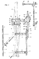
- FIG. 1 shows an overview of the instruments, which comprises the essential components of the reference system according to the invention.
- the tibia T and femur F bones are also shown, to which the reference system is applied.
- the lateral fastening arms 2 are arranged, which are connected to the measuring rod by means of the fastening means 3.
- the dipstick is attached to the tibia T by means of the bulwark screws 4 through the holes 5 in the mounting arms 2.
- the associated bores 5 for the modified bulwark screws are drilled in the tibia in the course of the preparation for the operation with the jig 6, the drilling jig being fixed to the tibia head with a Steinmann nail driven through the bore 7 into the tibia head.
- a guide rail 9 is fastened to the measuring rod 1 by means of the fastening means 8.
- the scale 10 is visible on this guide rail.
- a measuring slide 11 is located on the guide rail 9 and can be moved in the area of the scale 10 into the position required for the osteotomies.
- the measuring rod 1 and the guide rail 9 could consist of one piece.
- the guide rail 9 is set back with respect to the frontal plane, so that the operating field is optimally released.
- a movable pointer 12 is arranged on the measuring slide, with which the scale can be calibrated for each operation.
- the measuring slide has guide rods 13 which serve to guide the guide element 14 of the cutting block 15.
- the cutting block 15 can be displaceably moved up and down on these guide rods 13.
- the cutting block 15 has slots 16 which are used to insert a sawing instrument and has various holes 17 for receiving Steinmann nails.
- the hole 18 is used to attach the stylus according to FIG. 3, which is flexed in the case of osteotomies on the femur Location of the knee is used.
- the opening 19 serves to insert a tensioning instrument for osteotomies on the flexed knee (cf. FIG. 2).
- a target rod 20 is removably arranged on the measuring rod 1. In the present illustration, this is shown in the removed state.
- the aiming rod 20 is fastened to the mandrel 22 and to a screw connection 23 by means of the hinge part 21.
- the aiming rod 20 can be folded away by rotating it 180 ° around the hinge, whereby unobstructed access to the operating field is achieved.
- the aiming rod 20 in the present embodiment can be telescopically pushed together, the pin 24 engaging in a groove providing security against rotation.
- the target element 26 is slidably attached by means of a removable holder 25. It can be fixed to the bracket 25 by tightening the screw.
- the target element 26 ends at its end in a button-like structure 27 which can be aligned with the reference point of the operation, namely a screw B in the anterior superior spine of the pelvis.
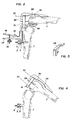
- the position of the cutting block 15 with the probe bracket 28 attached can be seen with respect to the flexed knee.
- the cutting block is attached to the femur F with two Steinmann nails 29.
- the ventral condyles 30 are osteotomized by means of the uppermost saw slot.
- the femur is pressed away from the tibia T by means of a tensioning instrument 31.
- the arm 49 of the tensioning instrument 31 for the flexed knee is inserted through window 19 in the cutting block 15.
- the arm of part 47 of the tensioning instrument 31 is on the upper modified bulwark 4 supported on the tibia T.
- the screw 32 is used to fix the parts 47 and 48.
- the osteotomy 33 of the ventral femoral condyles is indicated.
- Fig. 3 the probe bracket 28 is shown in perspective.
- FIG 4 shows in particular the cutting line 34, which indicates the position of the osteotomy of the dorsal condyles.
- FIG. 5 shows a side view of the reference system according to the invention with the knee extended.
- the attachment of the measuring rod 1 to the tibia T by the bulge screws 4 can be seen here.
- the guide rail 9 on which the measuring slide 11 is guided is set back with respect to the part of the measuring rod 1 fastened to the tibia. This results in better accessibility to the surgical field.
- the measuring slide 11 is attached, which has the movable pointer 12 for reading the scale.
- the guide rods 13, on which the cutting block 15 is movably attached by means of the guide element 14, are fastened to the slide.
- the aiming rod 20, which can be folded back by means of the hinge part 21, is fastened to the measuring rod 1 by means of the mandrel 22 and the screw connection 23. If necessary, the target rod 20 can be removed by loosening the nut 23 'on the screw 23. At the upper end of the target rod, the holder 25 can be seen, by means of which - the target element 26 can be brought into the correct position with the feeler element 27.
- Fig. 6 shows the same arrangement, but in a front view.
- the lateral fastening of the measuring rod 1 by means of the fastening arms 2, which are fastened to the tibia by the bulge screws 4, can be clearly seen here.
- the position of the cutting block 15 in front of the knee is also illustrated.
- the guide rail 9, on which the measuring slide 11 runs, is arranged such that the cutting block 15 can be brought into the correct position for all necessary cuts.
- the function of the target rod 20 with the target element 26 and the probe element 27 can be derived.
- the position of the tibia can be corrected at any time during the operation by placing the probe element 27 on a screw in the spina iliaca anterior superior as a reference point .
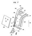
- FIG. 7 shows a tensioning instrument 35, the use of which is explained in more detail by FIG. 8.
- the part 36 has contact surfaces 37 for the osteotomized tibia.
- the parts 39 which have contact surfaces 40 for the femoral condyles.
- a mandrel 41 is arranged, at the end of which a thread 42 is present.
- the nut 43 with the radial groove 44 fits onto this thread.
- the parts 39 and the nuts 43 are held together on the part 36 by means of the plate 45 and the cover plate 46. By this arrangement the parts 39 can be moved precisely with respect to the part 36 by turning the nuts 43.
- the contact surfaces 37 and 40 remain parallel; only the distance changes.
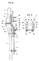
- FIG. 8 shows the use of the tensioning instrument 35 in connection with the reference system according to the invention.
- the representation of the reference system essentially corresponds to that of FIG. 5.
- the position of the instruments corresponds to the preparation for the osteotomy of the distal femoral condyles.
- the tibia is pressed away from the femur by the pressure of the contact surfaces 37, 40. Once the correct position has been set, the cutting block can be brought into the predetermined position and the osteotomy performed.
- FIG. 9 shows the tensioning instrument 35 from the front. It can be seen in particular how the contact surfaces 40 of the movable parts 39 act on the femoral condyles. It can be seen that by turning the nuts 43 provided with the groove, the distance between the tibia and femur can be increased or decreased.
- the downward-facing part 36 with the cover plate 46 provides optimum access to the operating field for performing osteotomies on the femur.
- An advantage of the instruments according to the invention is that the order of the osteotomies is up to the surgeon. With a joint with considerable fixed frontal deformity, he will first perform the osteotomy of the distal tibia and then perform a soft tissue release. The osteotomy of the ventral and dorsal femoral condyles after the ligament correction then ensures a stable joint, both in extension and in flexion. For joints with a largely correct axis position, the osteotomy of the ventral and dorsal femoral condyles can be started.
- the cutting block When using the cutting block in the flexed position of the knee, its position is determined by the feeler and by the Steinmann nails.
- the ventral condyles are osteotomized through the uppermost saw slot and that of the dorsal condyles through the middle saw slot.
- the distance between the holes in the cutting block for fixation by the Steinmann nails corresponds to the different prosthesis sizes.
- the cutting block can be lifted off and pushed back onto the two Steinmann nails by the distance between the holes.
- the cutting block can also be moved at right angles to the measuring rod on guide rods of the measuring carriage in the sagittal direction, it can be brought into the optimal position for each osteotomy on the tibia and femur.
- the position of the cutting block can be read according to the component sizes of the prostheses in a table attached to the instrument set.
- the correct leg axis position is checked with the aiming rod when the knee is stretched.
- the distance between the anterior superior iliac spine to the center of the hip joint is measured preoperatively on a pelvic overview and transmitted at the distal end of the target rod using the feeler element or spine pointer.
- the correct resection height is set on the measuring rod, the cutting block is screwed onto the osteotomized ventral condyles with a cortical screw with a diameter of 4.5 mm.
- the distal condyles are osteotomized through the lowest slot of the cutting block, the correct ligament tension is established with the help of the tensioner and the axis position is checked repeatedly with the aiming rod.
Abstract
Description
- Die vorliegende Erfindung betrifft ein Bezugssystem, welches es dem Chirurgen erlaubt, bei der Implantation von kondylären Knieprothesen die Osteotomien in äusserst präziser Weise durchzuführen. Dies ist eine Voraussetzung dafür, dass die Implantation so durchgeführt werden kann, dass durch die Operation die richtige mechanische Beinachse realisiert wird.
- Es ist erwiesen, dass die Verwirklichung der richtigen mechanischen Beinachse eine der wichtigsten Voraussetzungen für eine lange Lebensdauer der Knieprothese ohne Lokkerung und Schmerz ist (Bargren, J.H., Blaha, J.D., Freeman, M.A.R.: Alignment in Total Knee Arthroplasty, Clinical Orthopaedics and Related Research 173: 178 - 183, 1983).
- Dabei kommt es nicht nur darauf an, den richtigen statischen Knieaufbau (alignment) herzustellen, sondern es ist ebenfalls wichtig, dass die ausgewogene Spannung der Kniebänder, soweit sie erhalten sind bzw. die richtige Weichteilspannung vorliegt (F.C. Ewald: Biomechanical Indications for Implant Selection III: Knee. Role of Ligaments and Alignment, American Academy of Orthopaedic Surgeons, 54th Annual Meeting, San Francisco, January 22 - 27, 1987. Instructural Course Number 323).
- Die kondylären Knieprothesen bestehen aus einer am Femur und einer an der Tibia befestigten Komponente, die im Gegensatz zur Scharnierprothese nicht durch künstliche mechanische Hilfsmittel miteinander verbunden sind.
- Wie beim natürlichen Kniegelenk wird die flexible Verbindung zwischen den beiden Komponenten durch Bänder und Muskeln hergestellt, soweit diese bei der Implantation der Prothese erhalten bleiben. Bevor die Prothesenkomponenten auf dem Femur bzw. der Tibia durch Verklemmen, Verkeilen und/oder Knochenzement befestigt werden können, müssen Femur und Tibia mit Hilfe von Knochensägen und anderen Werkzeugen in die zur Prothese passende Form gebracht werden. Die im allgemeinen von den Herstellern der Knieprothese angebotenen Instrumente dienen in erster Linie dazu, die hierfür erforderlichen korrespondierenden Knochenschnitte am Femur und an der Tibia, die Osteotomien mit der notwendigen Genauigkeit vorzunehmen.
- Dabei ist es eine wesentliche Forderung, dass die bei der Biegung und Streckung des Knies aneinandergleitenden Komponenten der Knieprothese immer die richtige Stellung zueinander haben, d.h. dass die mechanische Beinachse maximal 3° Varus oder 3° Valgus von der physiologischen Beinachse abweichen darf und dass eine Equilibrierung des Bandapparates erreicht wird, die sowohl bei der Extension als auch bei der Flexion eine gute Stabilität des Kniegelenks bewirkt.
- Die bekannten Instrumentarien für die Implantation von kondylären Knie-Totalprothesen umfassen in der Regel fol gende Mittel:
- Mittel zur Ausrichtung der Tibia auf dem Femur zur Erzielung der gewünschten Beinachsenstellung.
- Mittel zur Durchführung von Osteotomien, in Form von Schneidlehren, welche der Führung der Säge dienen. Diese Schneidlehren sind auf bestimmte Prothesenformen abgestimmt und lassen sich meist für verschiedene Grössen eines Prothesentyps verwenden.
- Mittel zur Herstellung der gewünschten Spannung der Kniebänder. - Solche Instrumentarien sind beispielsweise in den folgenden Druckschriften beschrieben: Richards GmbH, Osterbrooksweg 69, 2000 Hamburg-Schenefeld: TRICON-M (R) "Die zementfreie Kniegelenksendoprothese", Operationstechnik mit dem ProFit TM Instrumentarium, ohne Datum. Pappas, M.J., Buechel, F.F.: N.J. Knee Instrumentation System: Biomechanical and Surgical Rationale, Biomedical Engineering Corp., Issue Date 7/1984. ZIMMER (R) Intramedullary Surgical Technique for the Miller/Galante Total Knee System, ohne Datum. Intermedics Orthopaedics, 1300 East Anderson Lane, Austin, Texas 78752: The Intermedics Natural-Knee TM System, 1986. Howmedica, Inc., Orthopaedics Division, 359 Veterans Blvd., Rutherford, N.J. 07070: The Howmedica (R) Total Knee Instrument System, 1980. Interplanta GmbH, Barkhausenweg 10, 2000 Hamburg 63: Schalen-Kniegelenkprothesen-System Modell Interplanta (C), W. Link, 1981.
- Die bekannten Instumentarien weisen den Nachteil auf, dass die Schneidlehre für die Osteotomien zwei Bezugssysteme besitzt, nämlich eines an der Tibia für Schnitte an derselben und ein zweites am Femur für Schnitte am Femur. Zur Bestimmung der Schnittebenen und zur Ausführung der Osteotomie mit der Säge an der Tibia werden Messmittel und Schneidlehre zunächst an der Tibia, z.B. mit Steinmann-Nägeln oder Knochenschrauben befestigt. Nach der Ausführung der Tibia-Schnitte werden Messmittel und Schneidlehre am Femur befestigt. Durch diesen Wechsel ist eine genaue geometrische Beziehung zwischen der Tibia-seitigen und der Femur-seitigen Gelenkprothesenkomponente nicht gewährleistet. Tatsächlich sind diesbezügliche Fehler jedem Chirurgen, der kondyläre Knie-Totalprothesen implantiert, bekannt. Solche Fehler sind beispielsweise beschrieben von Lotke, P.A., Ecker, M.L.: Influence of Positioning of Prosthesis in Total Knee Replacement, J. of Bone and Joint Surgery 55-A, 1977, 77 - 79.
- Es wurden auch schon Massnahmen getroffen, um den genannten Nachteil zu vermeiden, beispielsweise indem das Knie mittels einer mechanischen Vorrichtung am Operationstisch befestigt wurde, wobei auch die Säge mit dieser Vorrichtung verbunden war (siehe Cooke, T.D.V., Saunders, G., Siu, D., Yoshioka, Y., Wevers, W.: Application of bench mounted saws for precision arthroplasty of the arthritic knee (Questor knee jigs). Abstract Book, Second European Congress of Knee Surgery and Arthroscopy, Basel, September 29 - October 4, 1986, p. 110 - 111. J. Biomed. Eng. 7: 45 - 50, 1985).
- Die in den genannten Publikationen beschriebenen Vorrichtungen umfassen aufwendige mechanische Konstruktionen, deren Anwendung zeitaufwendig ist und ebenfalls den Zugang zum Operationsfeld behindern.
- Es ist demzufolge Aufgabe der vorliegenden Erfindung, ein Instrumentarium zu schaffen, welches die obenbeschriebenen Nachteile der bekannten Instrumentarien vermeidet.
- Es wurde gefunden, dass diese Aufgabe gelöst werden konnte, indem ein Bezugssystem zur Implantation von kondylären Knie-Totalprothesen geschaffen wurde, in welchem die Messmittel und die Schneidlehre für die tibialen und femoralen Osteotomien allein an der Tibia befestigt sind. Das Bezugssystem muss so ausgebildet sein, dass es während der gesamten Operation an der Tibia angeschraubt bleiben kann, ohne dass der Zugang zum Operationsfeld wesentlich behindert wird und ohne dass Bewegungen des Kniegelenkes verhindert werden.
- Gegenstand der vorliegenden Erfindung ist demzufolge das in Patentanspruch 1 definierte Bezugssystem zur Implantation von kondylären Knie-Totalprothesen.
- Das erfindungsgemässe Bezugssystem stellt ein Instrumentarium dar, mit welchem die Schneidlehre für die tibialen und femoralen Osteotomien vom gleichen Bezugspunkt aus eingestellt werden kann. Das Instrumentarium ist dabei vorzugsweise mittels zwei Befestigungsarmen seitlich an der Tibia mittels modifizierten Schanzschrauben befestigt. Das Basiselement des Instrumentariums ist der Messstab, welcher mittels der erwähnten Befestigungsarme vorzugsweise etwa 10 cm von der Tibiaachse entfernt befestigt wird. An diesem Messstab ist der Schneidblock auf der Führungsschiene beweglich angebracht, welcher präzise vor dem eröffneten Knie in Position gebracht werden kann. Am genannten Messstab ist ebenfalls ein sogenannter Zielstab vorhanden, welcher im wesentlichen die Verlängerung des Messtabs darstellt und bis in die Gegend des Beckenknochens reicht. Vor der Operation wird ein Zielelement, welches oben am Zielstab verschiebbar angeordnet ist bezüglich des Zielstabs z.B. mit einer Schraube so fixiert, dass es auf einen bestimmten Punkt am Beckenknochen zeigt. Dieser Punkt ist vorzugsweise eine in die Spina iliaca anterior superior senkrecht zur Frontalebene eingeschraubte Schraube. Durch das erfindungsgemässe Bezugssystem kann auch während der Operation die Tibia bezüglich dem Femur jederzeit in die richtige Position gebracht werden. Dies ist insbesondere dann erforderlich, wenn Schnitte am Femur durchgeführt werden müssen und in einem späten Stadium der Operation zum richtigen Einsetzen der kondylären Knie-Totalprothese.
- Der Zielstab weist vorzugsweise an der Stelle, wo er mit dem Messstab verbunden ist, ein Gelenk auf, welches das Wegklappen erlaubt, damit die gute Zugänglichkeit des Operationsfeldes gewährleistet bleibt. Für die Osteotomie der ventralen und dorsalen Femurkondylen wird das Knie in flektierte Lage gebracht. Auch diese Position ist bei der Verwendung des erfindungsgemässen Bezugssystem möglich. Wird in der ersten Phase der Operation die Osteotomie der ventralen und dorsalen Femurkondylen, in der zweiten Phase die Osteotomie der Tibia und in der dritten Phase die Osteotomie der distalen Kondylen durchgeführt, wird vor der Durchführung dieser zweiten und dritten Phase zwischen die Tibia und das Femur ein Spanninstrument eingesetzt. In diesem Zustand ziehen die gespannten Bänder und Gewebe die beiden Knochen zusammen.
- Deshalb sind Hilfsmittel erforderlich, um die Tibia in die richtige Position zu bringen, damit die Osteotomien bei 90° flektiertem Gelenk an Tibia und Femur und bei gestrecktem Bein am Femur in korrekter Weise durchgeführt werden können. Ein solches Hilfsmittel ist das Spanninstrument. Es hat die Aufgabe, die Gelenkflächen der Tibia und des Femur auseinanderzudrücken, wobei dieser Vorgang durch das erfindungsgemässe Bezugssystem kontrolliert werden kann.
- Es sind zwei verschiedene Spanninstrumente vorgesehen, das eine für die Osteotomien am gestreckten, das andere für Osteotomien am flektierten Knie.
- Das erste Spanninstrument für die Osteotomien am gestreckten Knie ist vorzugsweise eine blockförmige Vorrichtung, die zwischen Femur und Tibia eingeführt werden kann, nachdem die Osteotomie des Tibiakopfes durchgeführt worden ist. Der Block ist vorzugsweise so ausgestaltet, dass auf seiner Oberseite zwei bewegliche Platten unabhängig voneinander parallel zu einer auf der Tibia aufliegenden Platte beispielsweise durch Anziehen von Schrauben in Richtung Femur verschoben werden können, so dass verschiedene Abstände zwischen der medialen und lateralen Femurkondyle eingestellt und verschiedene Kräfte ausgeübt werden können. Auf diese Weise ist es möglich, die Weichteilspannung medial und lateral richtig einzustellen und eine eventuell auszuführende Achsenkorrektur zu prüfen.
- Das zweite Spanninstrument ist nach dem Prinzip eine Spreizzange konstruiert und weist in Verbindung mit dem erfindungsgemässen Bezugssystem gegenüber bekannten derartigen Instrumenten eine Reihe von Vorteilen auf. Das Spanninstrument kann ohne Entfernung des Schneidblockes bei flektiertem Knie eingesetzt werden. Dabei kann ein Arm des Spanninstruments durch eine Oeffnung so eingeführt werden, dass es am Dach der Fossa intercondylica anliegt. Der andere Arm des Spanninstruments ist so ausgebildet, dass er sich auf einer unterhalb des Knies in die Tibia eingedrehten Knochenschraube abstützt. Diese Knochenschraube, eine modifizierte Schanzschraube, ist bereits zur Befestigung des knieseitigen Befestigungsarmes eingedreht worden. Die Abstützung an dieser Schraube hat gegenüber der Abstützung auf der dem Femur benachbarten Tibiaosteotomie den Vorteil, dass die Osteotomiefläche durch die Krafteinwirkung nicht beschädigt wird. Das Spanninstrument hat ferner den Vorteil, dass es durch die von den medial und lateral unterschiedlichen Weichteilkräften verursachte Rotation des Kniegelenks nicht beeinträchtigt, so dass diese Rotation geprüft und durch bekannte chirurgische Eingriffe an den Weichteilen in der gewünschten Weise verändert werden kann.
- Ist diese Position richtig, kann mit Hilfe der Skala an der Führungsschiene der Messschlitten mit dem Schneid block in die richtige Position zur Osteotomie der distalen Kondylen gebracht werden. Dabei ist der Abstand der Schnitte der Tibia und am Femur der einzusetzenden Prothese angepasst. Das erfindungsgemässe Bezugssystem ist nicht nur für die Osteotomien sondern ebenfalls beim Einsetzen der Prothesenkomponenten wichtig, da ihre korrekte Anpassung, bzw. die richtigen Achsenverhältnisse jederzeit während dieser entscheidenden Operationsphase kontrolliert werden können.
- Die laterale Anordnung des Bezugssystem verringert Parallaxenfehler bei der Kontrolle der Achsenstellung. Solche Parallaxenfehler sind bei frontalen Richtstäben von herkömmlichen Instrumentarien grösser, da die Neutralrotationslage des gestreckten Beines wegen der Abdeckung mit sterilen Tüchern intraoperativ nicht zuverlässig hergestellt werden kann.
- Die korrekte Beinachsenstellung bei gestrecktem Kniegelenk wird mit dem Zielstab kontrolliert. Hierzu wird präoperativ auf einer Beckenübersichtsaufnahme die Distanz von Spina zum Hüftgelenkzentrum gemessen und am distalen Ende des Instrumentariums auf das Zielelement bzw. den Spinazeiger übertragen.
- Das erfindungsgemässe Bezugssystem eignet sich grundsätzlich für eine beliebige Reihenfolge der Osteotomien. Diese Reihenfolge wird vom operierenden Chirurgen je nach dem Zustand des Kniegelenkes bzw. der vorliegenden Achsenstellung festgelegt.
- Im folgenden wird die Erfindung beispielsweise anhand der beiliegenden Zeichnungen näher erläutert. Es zeigen:
- Fig. 1 eine perspektivische Uebersichtszeichnung des erfindungsgemässen Bezugssystems und der Knochenteile, auf welche es angewendet wird,
- Fig. 2 das 90° flektierte, mit Hilfe eines Spanninstrumentes distrahierte Kniegelenk, auf welches das erfindungsgemässe Bezugssystem angewendet wird,
- Fig. 3 den Tastbügel in perspektivischer Darstellung,
- Fig. 4 das flektierte Kniegelenk mit Schneidblock und Tastbügel des erfindungsgemässen Bezugssystems, wobei die durchzuführenden Osteotomien sichtbar sind,
- Fig. 5 eine Seitenansicht des erfindungsgemässen Bezugssystem
- Fig. 6 eine Vorderansicht des erfindungsgemässen Bezugssystem
- Fig. 7 Explosionszeichnung eines Spanninstrumentes für das gestreckte Knie,
- Fig. 8 eine Seitenansicht des Bezugssystems, wobei die Wirkung des ersten Spanninstrumentes am gestreckten Knie zur Geltung kommt,
- Fig. 9 eine Vorderansicht des Spanninstrumentes für das gestreckte Knie.
- In Fig. 1 ist eine Uebersicht des Instrumentariums dargestellt, welches die wesentlichen Bestandteile des erfindungsgemässen Bezugssystems umfasst. Es sind ebenfalls die Knochen Tibia T und Femur F dargestellt, auf welche das Bezugssystem zur Anwendung kommt. Am Messstab 1 sind die lateralen Befestigungsarme 2 angeordnet, welche mittels den Befestigungsmitteln 3 mit dem Messstab verbunden sind. Der Messstab wird mittels der Schanzschrauben 4 durch die Löcher 5 in den Befestigungsarmen 2 an der Tibia T befestigt. Die zugehörigen Bohrungen 5 für die modifizierten Schanzschrauben werden im Zuge der Operationsvorbereitung mit der Lehre 6 in die Tibia gebohrt, wobei die Bohrlehre mit einem durch die Bohrung 7 in den Tibiakopf eingeschlagenen Steinmann-Nagel am Tibiakopf fixiert wird.
- Am Messstab 1 ist mittels den Befestigungsmitteln 8 eine Führungsschiene 9 befestigt. Auf dieser Führungsschiene ist die Skala 10 sichtbar. Auf der Führungsschiene 9 befindet sich ein Messschlitten 11, welcher im Bereich der Skala 10 in die für die Osteotomien erforderlichen Lage verschoben werden kann. Alternativ könnte der Messstab 1 und die Führungsschiene 9 aus einem Stück bestehen. Im vorliegenden Beispiel ist die Führungsschiene 9 bezüglich der Frontalebene zurückversetzt, damit das Operationsfeld optimal freigegeben wird. Am Messschlitten ist ein beweglicher Zeiger 12 angeordnet, mit welchem die Eichung der Skala für jede Operation vorgenommen werden kann. Der Messschlitten weist Führungsstäbe 13 auf, welche zur Führung des Führungselementes 14 des Schneidblokkes 15 dienen. Auf diesen Führungsstäben 13 kann der Schneidblock 15 fixierbar nach oben und unten verschoben werden. Der Schneidblock 15 weist Schlitze 16 auf, welche zur Einführung eines Sägeinstrumentes dienen und besitzt verschiedene Löcher 17 zur Aufnahme von Steinmann-Nägeln. Das Loch 18 dient zur Befestigung des Tastbügels gemäss Fig. 3, welcher bei Osteotomien am Femur in flektierter Lage des Knies zur Anwendung kommt. Die Oeffnung 19 dient zum Einführen eines Spanninstrumentes für Osteotomien am flektierten Knie (vgl. Fig. 2). Am Messstab 1 ist ein Zielstab 20 abnehmbar angeordnet. In der vorliegenden Darstellung ist dieser im abgenommenen Zustand dargestellt. Der Zielstab 20 wird mittels des Scharnierteils 21 am Dorn 22 und an einer Schraubverbindung 23 befestigt. Während der Operation kann der Zielstab 20 weggeklappt werden, indem er um 180° um das Scharnier gedreht wird, wobei ein unbehinderter Zugang zum Operationsfeld erreicht wird. Zur besseren Handhabung ist der Zielstab 20 in der vorliegenden Ausführungsform teleskopartig zusammenschiebbar, wobei der in eine Nut eingreifende Stift 24 eine Verdrehsicherung bewirkt. Mittels einer abnehmbaren Halterung 25 ist das Zielelement 26 verschiebbar angebracht. Es kann durch Anziehen der Schraube an der Halterung 25 fixiert werden. Das Zielelement 26 läuft an seinem Ende in ein knopfartiges Gebilde 27 aus, welches auf den Bezugspunkt der Operation, nämlich einer Schraube B in der Spina anterior superior des Beckens ausgerichtet werden kann.
- In den Fig. 2 und 3 ist die Position des Schneidblokkes 15 mit aufgesetztem Tastbügel 28 bezüglich des flektierten Knies ersichtlich. Der Schneidblock ist mit zwei Steinmann-Nägeln 29 am Femur F befestigt. Mittels des obersten Sägeschlitzes werden die ventralen Kondylen 30 osteotomiert. Dabei wird das Femur mittels eines Spanninstrumentes 31 von der Tibia T weggedrückt. Der Arm 49 des Spanninstrumentes 31 für das flektierte Knie wird durch Fenster 19 im Schneidblock 15 eingesetzt. Der Arm des Teils 47 des Spanninstrumentes 31 wird auf der oberen modifizierten Schanzschraube 4 an der Tibia T abgestützt. Die Schraube 32 dient zur Feststellung der Teile 47 und 48. Im weiteren ist die Osteotomie 33 der ventralen Femurkondylen angedeutet.
- In Fig. 3 ist der Tastbügel 28 in perspektivischer Darstellung abgebildet.
- In Fig. 4 ist insbesondere auch die Schneidlinie 34 ersichtlich, welche die Lage der Osteotomie der dorsalen Kondylen anzeigt.
- Fig. 5 zeigt eine Seitenansicht des erfindungsgemässen Bezugssystem bei gestrecktem Knie. Hier ist die Befestigung des Messstabes 1 durch die Schanzschrauben 4 an der Tibia T ersichtlich. Im vorliegenden Beispiel ist die Führungsschiene 9, auf welcher der Messschlitten 11 geführt wird, bezüglich des an der Tibia befestigten Teils des Messstabes 1 zurückversetzt. Dadurch wird eine bessere Zugänglichkeit des Operationsfeldes bewirkt. Am zurückversetzten Teil des Messstabes ist der Messschlitten 11 angebracht, welcher den beweglichen Zeiger 12 zur Ablesung der Skala besitzt. Am Schlitten sind die Führungsstäbe 13 befestigt, auf welchen der Schneidblock 15 mittels dem Führungselement 14 beweglich angebracht ist. Am Messstab 1 ist mittels des Dornes 22 und der Schraubverbindung 23 der Zielstab 20 befestigt, welcher mittels des Scharnierteils 21 zurückgeklappt werden kann. Erforderlichenfalls kann der Zielstab 20 durch Lösen der Mutter 23′ an der Schraubverbindung 23 entfernt werden. Am oberen Ende des Zielstabes ist die Halterung 25 ersichtlich, mittels welcher - das Zielelement 26 mit dem Tastelement 27 in die richtige Lage gebracht werden kann.
- Die Fig. 6 zeigt die gleiche Anordnung, jedoch in Vorderansicht. Hier ist die laterale Befestigung des Messstabes 1 mittels der Befestigungsarme 2, die durch die Schanzschrauben 4 an der Tibia befestigt sind, deutlich ersichtlich. Es wird ebenfalls die Lage des Schneidblockes 15 vor dem Knie verdeutlicht. Die Führungsschiene 9, auf welcher der Messschlitten 11 läuft, ist so angeordnet, dass der Schneidblock 15 für sämtliche erforderlichen Schnitte in die richtige Position gebracht werden kann. Weiter kann die Funktion des Zielstabes 20 mit dem Zielelement 26 und dem Tastelement 27 abgeleitet werden. Ist vor der Operation die Lage des Zielelementes 26 am Zielstab 20 und der Abstand des Tastelementes 27 vom Zielstab 20 bestimmt, kann durch Anlegen des Tastelementes 27 an eine Schraube in der Spina iliaca anterior superior als Bezugspunkt die Lage der Tibia jederzeit während der Operation korrigiert werden.
- Fig. 7 zeigt ein Spanninstrument 35, deren Anwendung durch Fig. 8 näher erläutert wird. Der Teil 36 weist Auflageflächen 37 für die osteotomierte Tibia auf. In den Führungsnuten 38 sind die Teile 39 vorhanden, welche Auflageflächen 40 für die Femurkondylen aufweisen. An den Teilen 39 ist je ein Dorn 41 angeordnet, an dessen Ende ein Gewinde 42 vorhanden ist. Auf dieses Gewinde passt die Mutter 43 mit der radialen Nut 44. Mittels der Platte 45 und der Deckplatte 46 werden die Teile 39 und die Muttern 43 auf dem Teil 36 zusammengehalten. Durch diese Anordnung können durch Drehen der Muttern 43 die Teile 39 bezüglich dem Teil 36 präzise bewegt werden. Die Auflageflächen 37 und 40 bleiben dabei parallel; einzig der Abstand erfährt eine Aenderung.
- In Fig. 8 ist die Anwendung des Spanninstrumentes 35 im Zusammenhang mit dem erfindungsgemässen Bezugssystem dargestellt. Die Darstellung des Bezugssystems entspricht im wesentlichen derjenigen von Fig. 5. Im Gegensatz dazu ist hier die Osteotomie der Tibia und der dorsalen und ventralen Femurkondylen bereits durchgeführt. Die Lage des Instrumentariums entspricht der Vorbereitung für die Osteotomie der distalen Femurkondylen. Durch den Druck der Auflageflächen 37, 40 wird die Tibia vom Femur weggedrückt. Ist die korrekte Position eingestellt, kann der Schneidblock in die vorbestimmte Position gebracht und die Osteotomie durchgeführt werden.
- Fig. 9 zeigt das Spanninstrument 35 von vorne. Dabei ist insbesondere ersichtlich, wie die Auflageflächen 40 der beweglichen Teile 39 auf die Femurkondylen einwirken. Es ist ersichtlich, dass durch Drehen der mit der Nut versehenen Muttern 43 der Abstand von Tibia und Femur vergrössert oder verkleinert werden kann. Der nach unten gerichtete Teil 36 mit der Deckplatte 46 bewirkt eine optimale Zugänglichkeit des Operationsfeldes für die Durchführung von Osteotomien am Femur.
- Ein Vorteil des erfindungsgemässen Instrumentariums besteht darin, dass die Reihenfolge der Osteotomien dem Chirurgen freisteht. Bei einem Gelenk mit erheblicher fixierter frontaler Fehlstellung wird er zuerst die Osteotomie der distalen Tibia vornehmen und anschliessend ein Weichteil-Release durchführen. Die Osteotomie der ventralen und dorsalen Femurkondylen nach der Korrektur der Ligamente, gewährleistet dann ein stabiles Gelenk, sowohl in Extension als auch in Flexion. Bei Gelenken mit weitgehend korrekter Achsenstellung kann mit der Osteotomie der ventralen und dorsalen Femurkondylen begonnen werden.
- Bei der Verwendung des Schneidblockes in der flektierten Stellung des Knies, wird dessen Lage durch den Tastbügel und durch die Steinmann-Nägel bestimmt. Die Osteotomie der ventralen Kondylen erfolgt durch den obersten Sägeschlitz und diejenige der dorsalen Kondylen durch den mittleren Sägeschlitz. Der Abstand der Bohrungen im Schneidblock für die Fixierung durch die Steinmann-Nägel entspricht den verschiedenen Prothesengrössen. Der Schneidblock kann abgehoben und um den Bohrungsabstand verschoben wieder auf die zwei Steinmann-Nägel aufgesteckt werden.
- Durch die Möglichkeit, dass der Schneidblock zusätzlich rechtwinklig zum Messstab auf Führungsstäben des Messschlittens in sagittaler Richtung verschiebbar ist, kann er für jede Osteotomie an Tibia und Femur in die optimale Position gebracht werden.
- Die Lage des Schneidblockes kann entsprechend der Komponentengrössen der Prothesen einer dem Instrumentarium beigegebenen Tabelle abgelesen werden.
- Wie schon erwähnt, wird die korrekte Beinachsenstellung bei gestrecktem Kniegelenk mit dem Zielstab kontrolliert. Präoperativ wird auf einer Beckenübersichtsaufnahme die Distanz zwischen Spina iliaca anterior superior zum Hüftgelenkszentrum gemessen und am distalen Ende des Zielstabes mittels dem Tastelement oder Spinazeiger übertragen.
- Die richtige Resektionshöhe wird am Messstab eingestellt, der Schneidblock wird auf die osteotomierten ventralen Kondylen mit einer Corticalisschraube mit einem Durchmesser von 4,5 mm aufgeschraubt. Die distalen Kondylen werden durch den untersten Schlitz des Schneidblockes osteotomiert, wobei die korrekte Bandspannung mit Hilfe des Spanners hergestellt wird und die Achsenstellung mit dem Zielstab wiederholt kontrolliert wird.
Claims (12)
Applications Claiming Priority (2)
| Application Number | Priority Date | Filing Date | Title |
|---|---|---|---|
| CH4904/87 | 1987-12-16 | ||
| CH490487 | 1987-12-16 |
Publications (2)
| Publication Number | Publication Date |
|---|---|
| EP0322363A1 true EP0322363A1 (de) | 1989-06-28 |
| EP0322363B1 EP0322363B1 (de) | 1992-12-30 |
Family
ID=4284569
Family Applications (1)
| Application Number | Title | Priority Date | Filing Date |
|---|---|---|---|
| EP88810867A Expired - Lifetime EP0322363B1 (de) | 1987-12-16 | 1988-12-16 | Bezugssystem zur Implantation von kondylären Knie-Totalprothesen |
Country Status (3)
| Country | Link |
|---|---|
| US (1) | US4938762A (de) |
| EP (1) | EP0322363B1 (de) |
| DE (1) | DE3877174D1 (de) |
Cited By (19)
| Publication number | Priority date | Publication date | Assignee | Title |
|---|---|---|---|---|
| EP0469966A1 (de) * | 1990-07-31 | 1992-02-05 | Faro Medical Technologies (Us) Inc. | Computerunterstützte chirurgische Vorrichtung |
| FR2679766A1 (fr) * | 1991-07-30 | 1993-02-05 | Sophia Med | Dispositif de pose d'une prothese du genou. |
| EP0551572A2 (de) * | 1991-12-10 | 1993-07-21 | Bristol-Myers Squibb Company | Führer für Strienbeinosteotomie |
| US5251127A (en) * | 1988-02-01 | 1993-10-05 | Faro Medical Technologies Inc. | Computer-aided surgery apparatus |
| EP0574656A1 (de) * | 1992-06-18 | 1993-12-22 | D. Barclay Slocum | Passer zur Osteotomie |
| WO1994000056A1 (en) * | 1992-06-29 | 1994-01-06 | Minnesota Mining And Manufacturing Company | Sizing and cutting guide for resecting the distal end of the femur |
| US5305203A (en) * | 1988-02-01 | 1994-04-19 | Faro Medical Technologies Inc. | Computer-aided surgery apparatus |
| FR2703584A1 (fr) * | 1993-04-07 | 1994-10-14 | Medinov Sa | Viseur de coupes tibiales. |
| WO1995000076A1 (en) * | 1993-06-21 | 1995-01-05 | Osteonics Corp. | Apparatus and method for aligning knee prostheses |
| EP0677274A2 (de) * | 1994-02-22 | 1995-10-18 | Osteonics Corp. | Methode und Gerät zur Ausrichtung des Femurteils einer Knieprothese |
| EP0720834A3 (de) * | 1995-01-06 | 1996-07-17 | Bristol-Myers Squibb Company | Instrumentation zur Verwendung in der orthopädischen Chirurgie |
| US5611353A (en) * | 1993-06-21 | 1997-03-18 | Osteonics Corp. | Method and apparatus for locating functional structures of the lower leg during knee surgery |
| DE19709960A1 (de) * | 1997-03-11 | 1998-09-24 | Aesculap Ag & Co Kg | Verfahren und Vorrichtung zur präoperativen Bestimmung der Positionsdaten von Endoprothesenteilen |
| WO2000000093A1 (de) | 1998-06-29 | 2000-01-06 | Plus Endoprothetik Ag | Vorrichtung und verfahren zum einsetzen einer knieprothese |
| DE29910761U1 (de) * | 1999-06-19 | 2000-11-23 | Mathys Medizinaltechnik Ag Bet | Bänderspannvorrichtung für nicht-kugelige Gelenke |
| WO2002009596A1 (de) | 2000-07-28 | 2002-02-07 | Biomet Merck Gmbh | Vorrichtung zur ausrichtung einer führungsschablone |
| FR2899091A1 (fr) * | 2006-04-04 | 2007-10-05 | Michel Assor | Systeme ancillaire de pose de prothese totale du genou par voie minimale sans effraction du quadriceps, avec reglage de l'equilibre ligamentaire et de la rotation horizontale |
| EP1859748A1 (de) * | 2006-05-27 | 2007-11-28 | Depuy International Limited | Führungsanordnung |
| WO2012113735A1 (de) | 2011-02-21 | 2012-08-30 | Christoph Weber | Patientenspezifischer proberepositionsblock |
Families Citing this family (129)
| Publication number | Priority date | Publication date | Assignee | Title |
|---|---|---|---|---|
| US6347240B1 (en) | 1990-10-19 | 2002-02-12 | St. Louis University | System and method for use in displaying images of a body part |
| DE69132412T2 (de) | 1990-10-19 | 2001-03-01 | Univ St Louis | Lokalisierungssystem für eine chirurgische sonde zur anwendung am kopf |
| US5514143A (en) * | 1991-11-27 | 1996-05-07 | Apogee Medical Products, Inc. | Apparatus and method for use during surgery |
| US5603318A (en) | 1992-04-21 | 1997-02-18 | University Of Utah Research Foundation | Apparatus and method for photogrammetric surgical localization |
| US5464406A (en) * | 1992-12-09 | 1995-11-07 | Ritter; Merrill A. | Instrumentation for revision surgery |
| CA2161430C (en) | 1993-04-26 | 2001-07-03 | Richard D. Bucholz | System and method for indicating the position of a surgical probe |
| US5431653A (en) * | 1993-07-06 | 1995-07-11 | Callaway; George H. | Knee joint flexion-gap distraction device |
| US5908424A (en) * | 1994-05-16 | 1999-06-01 | Zimmer, Inc, By Said Stalcup, Dietz, Bays And Vanlaningham | Tibial milling guide system |
| DE4423717C1 (de) * | 1994-07-08 | 1996-01-04 | Eska Medical Gmbh & Co | Vorrichtung zur Festlegung von Resektionsflächen am Femur und an der Tibia zur Vorbereitung einer Implantation einer Kniegelenkstotalendoprothese |
| US8603095B2 (en) | 1994-09-02 | 2013-12-10 | Puget Bio Ventures LLC | Apparatuses for femoral and tibial resection |
| US5597379A (en) * | 1994-09-02 | 1997-01-28 | Hudson Surgical Design, Inc. | Method and apparatus for femoral resection alignment |
| US6695848B2 (en) | 1994-09-02 | 2004-02-24 | Hudson Surgical Design, Inc. | Methods for femoral and tibial resection |
| US5643272A (en) * | 1994-09-02 | 1997-07-01 | Hudson Surgical Design, Inc. | Method and apparatus for tibial resection |
| CA2201877C (en) | 1994-10-07 | 2004-06-08 | Richard D. Bucholz | Surgical navigation systems including reference and localization frames |
| US6978166B2 (en) | 1994-10-07 | 2005-12-20 | Saint Louis University | System for use in displaying images of a body part |
| US5649929A (en) * | 1995-07-10 | 1997-07-22 | Callaway; George Hadley | Knee joint flexion-gap distraction device |
| US5733292A (en) * | 1995-09-15 | 1998-03-31 | Midwest Orthopaedic Research Foundation | Arthroplasty trial prosthesis alignment devices and associated methods |
| WO1997030648A1 (en) * | 1996-02-23 | 1997-08-28 | Midwest Orthopedic Research Foundation | Device and method for distal femur cutting and prothesis measuring |
| US6167145A (en) | 1996-03-29 | 2000-12-26 | Surgical Navigation Technologies, Inc. | Bone navigation system |
| US5830216A (en) * | 1996-10-30 | 1998-11-03 | Bristol-Myers Squibb Company | Apparatus and method for knee implantation |
| US5788700A (en) * | 1996-10-30 | 1998-08-04 | Osteonics Corp. | Apparatus and method for the alignment of a total knee prosthesis |
| US5735856A (en) * | 1997-01-31 | 1998-04-07 | Johnson & Johnson Professional, Inc. | Orthopedic cutting guide and bushing |
| US5916219A (en) * | 1997-02-10 | 1999-06-29 | Matsuno; Shigeo | Tibial plateau resection guide |
| US6090114A (en) * | 1997-02-10 | 2000-07-18 | Stryker Howmedica Osteonics Corp. | Tibial plateau resection guide |
| US7635390B1 (en) | 2000-01-14 | 2009-12-22 | Marctec, Llc | Joint replacement component having a modular articulating surface |
| WO2001066022A1 (en) | 2000-03-10 | 2001-09-13 | Smith & Nephew, Inc | Apparatus for use in arthroplasty of the knees |
| ATE279884T1 (de) * | 2000-05-31 | 2004-11-15 | Stratec Medical Ag | Vorrichtung zur positionierung eines chirurgischen instrumentes |
| US6478799B1 (en) * | 2000-06-29 | 2002-11-12 | Richard V. Williamson | Instruments and methods for use in performing knee surgery |
| US6612977B2 (en) * | 2001-01-23 | 2003-09-02 | American Medical Systems Inc. | Sling delivery system and method of use |
| US7547307B2 (en) | 2001-02-27 | 2009-06-16 | Smith & Nephew, Inc. | Computer assisted knee arthroplasty instrumentation, systems, and processes |
| US8062377B2 (en) | 2001-03-05 | 2011-11-22 | Hudson Surgical Design, Inc. | Methods and apparatus for knee arthroplasty |
| US6770077B2 (en) * | 2001-05-21 | 2004-08-03 | Nemco Medical, Ltd. | Femoral knee saw guide and method |
| US6482209B1 (en) * | 2001-06-14 | 2002-11-19 | Gerard A. Engh | Apparatus and method for sculpting the surface of a joint |
| US6723102B2 (en) * | 2001-06-14 | 2004-04-20 | Alexandria Research Technologies, Llc | Apparatus and method for minimally invasive total joint replacement |
| US7708741B1 (en) | 2001-08-28 | 2010-05-04 | Marctec, Llc | Method of preparing bones for knee replacement surgery |
| US7618421B2 (en) | 2001-10-10 | 2009-11-17 | Howmedica Osteonics Corp. | Tools for femoral resection in knee surgery |
| ES2329346T3 (es) * | 2001-11-14 | 2009-11-25 | Durect Corporation | Composicion de deposito inyectable. |
| WO2003063682A2 (en) * | 2002-01-25 | 2003-08-07 | Depuy Products, Inc. | Extramedullary fluoroscopic alignment guide |
| CA2475979A1 (en) * | 2002-02-11 | 2003-08-21 | Smith & Nephew, Inc. | Image-guided fracture reduction |
| US7799084B2 (en) | 2002-10-23 | 2010-09-21 | Mako Surgical Corp. | Modular femoral component for a total knee joint replacement for minimally invasive implantation |
| US7094241B2 (en) * | 2002-11-27 | 2006-08-22 | Zimmer Technology, Inc. | Method and apparatus for achieving correct limb alignment in unicondylar knee arthroplasty |
| US20040122439A1 (en) * | 2002-12-20 | 2004-06-24 | Dwyer Kimberly A. | Adjustable biomechanical templating & resection instrument and associated method |
| US7854737B2 (en) * | 2002-12-20 | 2010-12-21 | Depuy Products, Inc. | Instrument and associated method of trailing for modular hip stems |
| US7235106B2 (en) * | 2002-12-20 | 2007-06-26 | Depuy Products, Inc. | Modular hip stems and associated method of trialing |
| US7235080B2 (en) * | 2003-02-20 | 2007-06-26 | Zimmer Technology, Inc. | Femoral reference tibial cut guide |
| ES2261812T3 (es) * | 2003-04-25 | 2006-11-16 | Zimmer Gmbh | Dispositivo para la preparacion de un condilo femoral. |
| ES2261813T3 (es) * | 2003-04-25 | 2006-11-16 | Zimmer Gmbh | Dispositivo para la definicion de cortes oseos. |
| JP4231813B2 (ja) * | 2003-05-06 | 2009-03-04 | ツィマー ゲーエムベーハー | 牽引装置 |
| US20050021037A1 (en) * | 2003-05-29 | 2005-01-27 | Mccombs Daniel L. | Image-guided navigated precision reamers |
| US7559931B2 (en) | 2003-06-09 | 2009-07-14 | OrthAlign, Inc. | Surgical orientation system and method |
| US8057482B2 (en) * | 2003-06-09 | 2011-11-15 | OrthAlign, Inc. | Surgical orientation device and method |
| DE50300339D1 (de) * | 2003-09-15 | 2005-04-07 | Zimmer Gmbh Winterthur | Einstellvorrichtung |
| FR2859902B1 (fr) * | 2003-09-23 | 2005-11-25 | Michel Assor | Dispositif de pose sans malposition rotatoire dans les trois plan de l'espace d'une prothese unicompartimentale (et par extension totale)du genou |
| US7862570B2 (en) | 2003-10-03 | 2011-01-04 | Smith & Nephew, Inc. | Surgical positioners |
| CA2538126A1 (en) * | 2003-10-06 | 2005-05-06 | Smith & Nephew, Inc. | Modular navigated portal |
| US7764985B2 (en) | 2003-10-20 | 2010-07-27 | Smith & Nephew, Inc. | Surgical navigation system component fault interfaces and related processes |
| DE602004031147D1 (de) | 2003-11-14 | 2011-03-03 | Smith & Nephew Inc | |
| US8657824B2 (en) | 2003-11-18 | 2014-02-25 | Smith & Nephew, Inc. | Universal double offset surgical instrument |
| DE602004023422D1 (de) | 2003-11-18 | 2009-11-12 | Smith & Nephew Inc | Operationstechnik und instrumente für die minimalinzisions-hüft-arthoplastiechirurgie |
| US7641661B2 (en) * | 2003-12-26 | 2010-01-05 | Zimmer Technology, Inc. | Adjustable resection guide |
| US7815645B2 (en) | 2004-01-14 | 2010-10-19 | Hudson Surgical Design, Inc. | Methods and apparatus for pinplasty bone resection |
| US20060030854A1 (en) | 2004-02-02 | 2006-02-09 | Haines Timothy G | Methods and apparatus for wireplasty bone resection |
| US8114083B2 (en) | 2004-01-14 | 2012-02-14 | Hudson Surgical Design, Inc. | Methods and apparatus for improved drilling and milling tools for resection |
| US8021368B2 (en) | 2004-01-14 | 2011-09-20 | Hudson Surgical Design, Inc. | Methods and apparatus for improved cutting tools for resection |
| US7857814B2 (en) | 2004-01-14 | 2010-12-28 | Hudson Surgical Design, Inc. | Methods and apparatus for minimally invasive arthroplasty |
| US20050171545A1 (en) * | 2004-01-30 | 2005-08-04 | Howmedica Osteonics Corp. | Knee computer-aided navigation instruments |
| US20060030855A1 (en) | 2004-03-08 | 2006-02-09 | Haines Timothy G | Methods and apparatus for improved profile based resection |
| FR2867963B1 (fr) * | 2004-03-26 | 2006-06-02 | Francis Guillaume | Ensemble d'ancillaires pour implanter une prothese de genou |
| WO2005096982A1 (en) | 2004-03-31 | 2005-10-20 | Smith & Nephew, Inc. | Methods and apparatuses for providing a reference array input device |
| US8109942B2 (en) | 2004-04-21 | 2012-02-07 | Smith & Nephew, Inc. | Computer-aided methods, systems, and apparatuses for shoulder arthroplasty |
| US7507242B2 (en) * | 2004-06-02 | 2009-03-24 | Facet Solutions | Surgical measurement and resection framework |
| US8167888B2 (en) | 2004-08-06 | 2012-05-01 | Zimmer Technology, Inc. | Tibial spacer blocks and femoral cutting guide |
| US20060155293A1 (en) * | 2005-01-07 | 2006-07-13 | Zimmer Technology | External rotation cut guide |
| US8317797B2 (en) | 2005-02-08 | 2012-11-27 | Rasmussen G Lynn | Arthroplasty systems and methods for optimally aligning and tensioning a knee prosthesis |
| US8303597B2 (en) | 2005-02-08 | 2012-11-06 | Rasmussen G Lynn | Systems and methods for guiding cuts to a femur and tibia during a knee arthroplasty |
| CA2601976A1 (en) | 2005-02-22 | 2006-08-31 | Smith & Nephew, Inc. | In-line milling system |
| GB0519832D0 (en) * | 2005-09-30 | 2005-11-09 | Depuy Int Ltd | Instrument assembly for use in knee joint replacement surgery |
| GB0519829D0 (en) | 2005-09-30 | 2005-11-09 | Depuy Int Ltd | Distractor instrument |
| US7780671B2 (en) * | 2006-01-23 | 2010-08-24 | Zimmer Technology, Inc. | Bone resection apparatus and method for knee surgery |
| US20080015602A1 (en) * | 2006-06-22 | 2008-01-17 | Howmedica Osteonics Corp. | Cutting block for bone resection |
| US20110208200A1 (en) * | 2006-08-15 | 2011-08-25 | Gary Keffer | Veterinary precision fixation device and method of using the same |
| US7805853B2 (en) * | 2006-08-31 | 2010-10-05 | David H Littig | Transfemoral pelvic impression system |
| US8398645B2 (en) | 2007-09-30 | 2013-03-19 | DePuy Synthes Products, LLC | Femoral tibial customized patient-specific orthopaedic surgical instrumentation |
| US8197489B2 (en) * | 2008-06-27 | 2012-06-12 | Depuy Products, Inc. | Knee ligament balancer |
| EP2344078B1 (de) | 2008-07-24 | 2018-04-18 | OrthAlign, Inc. | Systeme zum gelenkersatz |
| US8337498B2 (en) | 2008-08-13 | 2012-12-25 | Rasmussen G Lynn | Systems and methods for providing a bone milling device |
| EP2358310B1 (de) | 2008-09-10 | 2019-07-31 | OrthAlign, Inc. | Systeme für die hüftchirurgie |
| US8721568B2 (en) | 2009-03-31 | 2014-05-13 | Depuy (Ireland) | Method for performing an orthopaedic surgical procedure |
| US8597210B2 (en) | 2009-03-31 | 2013-12-03 | Depuy (Ireland) | System and method for displaying joint force data |
| US8740817B2 (en) | 2009-03-31 | 2014-06-03 | Depuy (Ireland) | Device and method for determining forces of a patient's joint |
| US8551023B2 (en) * | 2009-03-31 | 2013-10-08 | Depuy (Ireland) | Device and method for determining force of a knee joint |
| US8556830B2 (en) | 2009-03-31 | 2013-10-15 | Depuy | Device and method for displaying joint force data |
| US10869771B2 (en) | 2009-07-24 | 2020-12-22 | OrthAlign, Inc. | Systems and methods for joint replacement |
| US8118815B2 (en) * | 2009-07-24 | 2012-02-21 | OrthAlign, Inc. | Systems and methods for joint replacement |
| EP2525740A4 (de) | 2010-01-21 | 2016-01-20 | Orthalign Inc | Systeme und verfahren für den ersatz von gelenken |
| GB201115411D0 (en) | 2011-09-07 | 2011-10-19 | Depuy Ireland | Surgical instrument |
| US9138237B2 (en) * | 2011-10-13 | 2015-09-22 | Arthrex, Inc. | Total joint instrumentation and method for use |
| US9381011B2 (en) | 2012-03-29 | 2016-07-05 | Depuy (Ireland) | Orthopedic surgical instrument for knee surgery |
| US9545459B2 (en) | 2012-03-31 | 2017-01-17 | Depuy Ireland Unlimited Company | Container for surgical instruments and system including same |
| US10098761B2 (en) | 2012-03-31 | 2018-10-16 | DePuy Synthes Products, Inc. | System and method for validating an orthopaedic surgical plan |
| US10206792B2 (en) | 2012-03-31 | 2019-02-19 | Depuy Ireland Unlimited Company | Orthopaedic surgical system for determining joint forces of a patients knee joint |
| US10070973B2 (en) | 2012-03-31 | 2018-09-11 | Depuy Ireland Unlimited Company | Orthopaedic sensor module and system for determining joint forces of a patient's knee joint |
| JP2015517361A (ja) | 2012-05-18 | 2015-06-22 | オースアライン・インコーポレイテッド | 膝関節形成術用の装置および方法 |
| US9649160B2 (en) | 2012-08-14 | 2017-05-16 | OrthAlign, Inc. | Hip replacement navigation system and method |
| US9730712B2 (en) * | 2012-10-18 | 2017-08-15 | Smith & Nephew, Inc. | Alignment devices and methods |
| US9770272B2 (en) | 2012-12-12 | 2017-09-26 | Wright Medical Technology, Inc. | Orthopedic compression/distraction device |
| US11793424B2 (en) | 2013-03-18 | 2023-10-24 | Orthosensor, Inc. | Kinetic assessment and alignment of the muscular-skeletal system and method therefor |
| US9820678B2 (en) | 2013-03-18 | 2017-11-21 | Orthosensor Inc | Kinetic assessment and alignment of the muscular-skeletal system and method therefor |
| CN103845104B (zh) | 2014-03-19 | 2015-03-25 | 张英泽 | 能分散应力的髂前上棘及髂嵴适形固定连接装置 |
| JP6601812B2 (ja) * | 2014-03-28 | 2019-11-06 | アルスロデザイン株式会社 | 関節置換術用手術具 |
| CN103932771B (zh) * | 2014-04-03 | 2014-11-26 | 张英泽 | 不易造成髂前上棘及髂嵴损坏的牵引固定连接器 |
| EP3215070B1 (de) * | 2014-11-07 | 2019-05-15 | Implantcast GmbH | Vorrichtung für gelenkrekonstruktion |
| JP6389740B2 (ja) * | 2014-11-26 | 2018-09-12 | 京セラ株式会社 | 人工膝関節置換術用手術器具 |
| US10363149B2 (en) | 2015-02-20 | 2019-07-30 | OrthAlign, Inc. | Hip replacement navigation system and method |
| US10517741B2 (en) * | 2015-03-06 | 2019-12-31 | Tornier, Inc. | Surgical method and instrumentation assembly for positioning an ankle prosthesis |
| US10568650B2 (en) | 2015-03-25 | 2020-02-25 | E. Marlowe Goble | Knee instruments and methods |
| JP6949001B2 (ja) | 2015-03-25 | 2021-10-13 | ゴーブル イー.マーロウ | 膝関節器具及び方法 |
| DE102015105931A1 (de) * | 2015-04-02 | 2016-10-06 | Aesculap Ag | Medizinische Führungsvorrichtung |
| CN104840240B (zh) * | 2015-05-21 | 2017-07-14 | 南方医科大学第三附属医院 | 一种股骨截骨辅助器 |
| US11406502B2 (en) | 2017-03-02 | 2022-08-09 | Optimotion Implants LLC | Orthopedic implants and methods |
| US11039938B2 (en) | 2017-07-26 | 2021-06-22 | Optimotion Implants LLC | Modular knee prothesis |
| JP6392470B1 (ja) * | 2017-03-03 | 2018-09-19 | 誠 五島 | 取付位置確認部材、骨切断補助キット、及び位置検出プログラム |
| JP7344122B2 (ja) | 2017-03-14 | 2023-09-13 | オースアライン・インコーポレイテッド | 軟部組織の測定およびバランシングを行うシステムおよび方法 |
| CA3056382A1 (en) | 2017-03-14 | 2018-09-20 | OrthAlign, Inc. | Hip replacement navigation systems and methods |
| WO2019115744A1 (en) | 2017-12-15 | 2019-06-20 | Depuy Ireland Unlimited Company | A knee balancing instrument |
| US11234720B2 (en) | 2018-03-07 | 2022-02-01 | E. Marlowe Goble | Knee instruments and methods |
| US11051829B2 (en) | 2018-06-26 | 2021-07-06 | DePuy Synthes Products, Inc. | Customized patient-specific orthopaedic surgical instrument |
| CN109009582B (zh) * | 2018-08-29 | 2020-07-28 | 中山市中医院 | 膝关节置换测量装置及测量系统 |
| EP3893772A4 (de) * | 2018-12-13 | 2022-11-23 | Paragon 28, Inc. | Resektionsführungen, kehrende fräser und verfahren zur verwendung beim vollständigen knöchelersatz |
Citations (4)
| Publication number | Priority date | Publication date | Assignee | Title |
|---|---|---|---|---|
| US3670724A (en) * | 1970-03-12 | 1972-06-20 | David N Bosacco | Prosthetic or fracture device and method |
| US4457307A (en) * | 1982-08-20 | 1984-07-03 | Stillwell William T | Bone cutting device for total knee replacement |
| US4524766A (en) * | 1982-01-07 | 1985-06-25 | Petersen Thomas D | Surgical knee alignment method and system |
| US4574794A (en) * | 1984-06-01 | 1986-03-11 | Queen's University At Kingston | Orthopaedic bone cutting jig and alignment device |
Family Cites Families (4)
| Publication number | Priority date | Publication date | Assignee | Title |
|---|---|---|---|---|
| US4567885A (en) * | 1981-11-03 | 1986-02-04 | Androphy Gary W | Triplanar knee resection system |
| US4487203A (en) * | 1981-11-03 | 1984-12-11 | Androphy Gary W | Triplanar knee resection method |
| US4567886A (en) * | 1983-01-06 | 1986-02-04 | Petersen Thomas D | Flexion spacer guide for fitting a knee prosthesis |
| US4566448A (en) * | 1983-03-07 | 1986-01-28 | Rohr Jr William L | Ligament tensor and distal femoral resector guide |
-
1988
- 1988-12-08 US US07/281,676 patent/US4938762A/en not_active Expired - Fee Related
- 1988-12-16 EP EP88810867A patent/EP0322363B1/de not_active Expired - Lifetime
- 1988-12-16 DE DE8888810867T patent/DE3877174D1/de not_active Expired - Fee Related
Patent Citations (4)
| Publication number | Priority date | Publication date | Assignee | Title |
|---|---|---|---|---|
| US3670724A (en) * | 1970-03-12 | 1972-06-20 | David N Bosacco | Prosthetic or fracture device and method |
| US4524766A (en) * | 1982-01-07 | 1985-06-25 | Petersen Thomas D | Surgical knee alignment method and system |
| US4457307A (en) * | 1982-08-20 | 1984-07-03 | Stillwell William T | Bone cutting device for total knee replacement |
| US4574794A (en) * | 1984-06-01 | 1986-03-11 | Queen's University At Kingston | Orthopaedic bone cutting jig and alignment device |
Cited By (28)
| Publication number | Priority date | Publication date | Assignee | Title |
|---|---|---|---|---|
| US5251127A (en) * | 1988-02-01 | 1993-10-05 | Faro Medical Technologies Inc. | Computer-aided surgery apparatus |
| US5305203A (en) * | 1988-02-01 | 1994-04-19 | Faro Medical Technologies Inc. | Computer-aided surgery apparatus |
| US5748767A (en) * | 1988-02-01 | 1998-05-05 | Faro Technology, Inc. | Computer-aided surgery apparatus |
| EP0469966A1 (de) * | 1990-07-31 | 1992-02-05 | Faro Medical Technologies (Us) Inc. | Computerunterstützte chirurgische Vorrichtung |
| FR2679766A1 (fr) * | 1991-07-30 | 1993-02-05 | Sophia Med | Dispositif de pose d'une prothese du genou. |
| EP0551572A2 (de) * | 1991-12-10 | 1993-07-21 | Bristol-Myers Squibb Company | Führer für Strienbeinosteotomie |
| EP0551572A3 (en) * | 1991-12-10 | 1993-10-20 | Bristol Myers Squibb Co | Tibial resector guide |
| EP0574656A1 (de) * | 1992-06-18 | 1993-12-22 | D. Barclay Slocum | Passer zur Osteotomie |
| WO1994000056A1 (en) * | 1992-06-29 | 1994-01-06 | Minnesota Mining And Manufacturing Company | Sizing and cutting guide for resecting the distal end of the femur |
| FR2703584A1 (fr) * | 1993-04-07 | 1994-10-14 | Medinov Sa | Viseur de coupes tibiales. |
| US5611353A (en) * | 1993-06-21 | 1997-03-18 | Osteonics Corp. | Method and apparatus for locating functional structures of the lower leg during knee surgery |
| US5520694A (en) * | 1993-06-21 | 1996-05-28 | Dance; Mark N. | Apparatus and method for aligning knee prostheses |
| AU679242B2 (en) * | 1993-06-21 | 1997-06-26 | Howmedica Osteonics Corp. | Apparatus and method for aligning knee prostheses |
| WO1995000076A1 (en) * | 1993-06-21 | 1995-01-05 | Osteonics Corp. | Apparatus and method for aligning knee prostheses |
| EP0677274A3 (de) * | 1994-02-22 | 1995-11-29 | Osteonics Corp | |
| EP0677274A2 (de) * | 1994-02-22 | 1995-10-18 | Osteonics Corp. | Methode und Gerät zur Ausrichtung des Femurteils einer Knieprothese |
| EP0720834A3 (de) * | 1995-01-06 | 1996-07-17 | Bristol-Myers Squibb Company | Instrumentation zur Verwendung in der orthopädischen Chirurgie |
| US6915150B2 (en) | 1997-03-11 | 2005-07-05 | Aesculap Ag & Co. Kg | Process and device for the preoperative determination of the positioning data of endoprosthetic parts |
| US6385475B1 (en) | 1997-03-11 | 2002-05-07 | Philippe Cinquin | Process and device for the preoperative determination of the positioning data of endoprosthetic parts |
| DE19709960A1 (de) * | 1997-03-11 | 1998-09-24 | Aesculap Ag & Co Kg | Verfahren und Vorrichtung zur präoperativen Bestimmung der Positionsdaten von Endoprothesenteilen |
| US7033360B2 (en) | 1997-03-11 | 2006-04-25 | Aesculap Ag & Co. Kg | Process and device for the preoperative determination of the positioning data endoprosthetic parts |
| WO2000000093A1 (de) | 1998-06-29 | 2000-01-06 | Plus Endoprothetik Ag | Vorrichtung und verfahren zum einsetzen einer knieprothese |
| US6554837B1 (en) | 1998-06-29 | 2003-04-29 | Plus Endoprothetik Ag | Device and method for inserting a prosthetic knee |
| DE29910761U1 (de) * | 1999-06-19 | 2000-11-23 | Mathys Medizinaltechnik Ag Bet | Bänderspannvorrichtung für nicht-kugelige Gelenke |
| WO2002009596A1 (de) | 2000-07-28 | 2002-02-07 | Biomet Merck Gmbh | Vorrichtung zur ausrichtung einer führungsschablone |
| FR2899091A1 (fr) * | 2006-04-04 | 2007-10-05 | Michel Assor | Systeme ancillaire de pose de prothese totale du genou par voie minimale sans effraction du quadriceps, avec reglage de l'equilibre ligamentaire et de la rotation horizontale |
| EP1859748A1 (de) * | 2006-05-27 | 2007-11-28 | Depuy International Limited | Führungsanordnung |
| WO2012113735A1 (de) | 2011-02-21 | 2012-08-30 | Christoph Weber | Patientenspezifischer proberepositionsblock |
Also Published As
| Publication number | Publication date |
|---|---|
| DE3877174D1 (de) | 1993-02-11 |
| US4938762A (en) | 1990-07-03 |
| EP0322363B1 (de) | 1992-12-30 |
Similar Documents
| Publication | Publication Date | Title |
|---|---|---|
| EP0322363B1 (de) | Bezugssystem zur Implantation von kondylären Knie-Totalprothesen | |
| EP1492461B1 (de) | Bänderspannvorrichtung mit schnittlehre | |
| DE602005003462T2 (de) | Hilfsanordnung zur implantation von knieprothesen | |
| EP1819280B1 (de) | Bänderspannvorrichtung und schnittlehre zur osteotomie | |
| DE60312628T2 (de) | Vorrichtung zum Ausrichten des Beines für eine unikondylare Arthroplastie des Knies | |
| EP0828455B1 (de) | Instrumentarium für umstellungs-osteotomie der unteren extremität | |
| EP1470786B1 (de) | Vorrichtung zur Vorbereitung einer Femurkondyle | |
| EP1091696B1 (de) | Vorrichtung zum einsetzen einer knieprothese | |
| DE60301635T2 (de) | Vorrichtung zum Einstellen des Beugungsabstandes einer Knieprosthese | |
| DE69630776T2 (de) | Instrument zur tibiaresektion | |
| DE69822197T2 (de) | Bohrlehre zum ansetzen einer bohrung am schienbein | |
| US4574794A (en) | Orthopaedic bone cutting jig and alignment device | |
| DE69534232T2 (de) | Vorrichtung zur femur- und tibiarresektion | |
| EP1786369B1 (de) | Chirurgisches instrument | |
| EP1304964A1 (de) | Vorrichtung zur ausrichtung einer führungsschablone | |
| DE3842645A1 (de) | Saegelehrensystem | |
| EP1139937A1 (de) | Knieprothesensystem | |
| DE10358926B4 (de) | Resektionsschnittlehre | |
| DE102010013258A1 (de) | Vorrichtung zur Positionierung von Schnittführungselementen | |
| EP1645229B1 (de) | Bänderkraft-Erfassungssystem | |
| EP1292235B1 (de) | Vorrichtung zur positionierung eines chirurgischen instrumentes | |
| DE69728430T2 (de) | Hilfsinstrument zur vorbereitung des einsetzens einer knieprothese | |
| EP3429484B1 (de) | Operationsvorrichtung für eine operation des menschlichen knies | |
| EP3753501A1 (de) | Schablone und sets für eine domosteotomie | |
| EP2081505B1 (de) | Schablone zum durchführen einer umstellungsosteotomie |
Legal Events
| Date | Code | Title | Description |
|---|---|---|---|
| PUAI | Public reference made under article 153(3) epc to a published international application that has entered the european phase |
Free format text: ORIGINAL CODE: 0009012 |
|
| AK | Designated contracting states |
Kind code of ref document: A1 Designated state(s): CH DE FR GB LI |
|
| 17P | Request for examination filed |
Effective date: 19891216 |
|
| 17Q | First examination report despatched |
Effective date: 19920218 |
|
| GRAA | (expected) grant |
Free format text: ORIGINAL CODE: 0009210 |
|
| AK | Designated contracting states |
Kind code of ref document: B1 Designated state(s): CH DE FR GB LI |
|
| REF | Corresponds to: |
Ref document number: 3877174 Country of ref document: DE Date of ref document: 19930211 |
|
| ET | Fr: translation filed | ||
| GBT | Gb: translation of ep patent filed (gb section 77(6)(a)/1977) |
Effective date: 19930330 |
|
| PLBE | No opposition filed within time limit |
Free format text: ORIGINAL CODE: 0009261 |
|
| STAA | Information on the status of an ep patent application or granted ep patent |
Free format text: STATUS: NO OPPOSITION FILED WITHIN TIME LIMIT |
|
| 26N | No opposition filed | ||
| REG | Reference to a national code |
Ref country code: CH Ref legal event code: PUE Owner name: PROTEK AG TRANSFER- DR. MED. ULRICH WEHRLI |
|
| REG | Reference to a national code |
Ref country code: GB Ref legal event code: 732E |
|
| REG | Reference to a national code |
Ref country code: FR Ref legal event code: TP |
|
| REG | Reference to a national code |
Ref country code: CH Ref legal event code: NV Representative=s name: DR. LUSUARDI AG |
|
| REG | Reference to a national code |
Ref country code: CH Ref legal event code: PUE Owner name: DR. MED. ULRICH WEHRLI TRANSFER- MATHYS AG BETTLAC |
|
| REG | Reference to a national code |
Ref country code: GB Ref legal event code: 732E |
|
| REG | Reference to a national code |
Ref country code: FR Ref legal event code: TP |
|
| REG | Reference to a national code |
Ref country code: GB Ref legal event code: IF02 |
|
| PGFP | Annual fee paid to national office [announced via postgrant information from national office to epo] |
Ref country code: GB Payment date: 20031208 Year of fee payment: 16 |
|
| PG25 | Lapsed in a contracting state [announced via postgrant information from national office to epo] |
Ref country code: GB Free format text: LAPSE BECAUSE OF NON-PAYMENT OF DUE FEES Effective date: 20041216 |
|
| GBPC | Gb: european patent ceased through non-payment of renewal fee |
Effective date: 20041216 |
|
| PGFP | Annual fee paid to national office [announced via postgrant information from national office to epo] |
Ref country code: FR Payment date: 20051103 Year of fee payment: 18 |
|
| PGFP | Annual fee paid to national office [announced via postgrant information from national office to epo] |
Ref country code: DE Payment date: 20051104 Year of fee payment: 18 |
|
| PGFP | Annual fee paid to national office [announced via postgrant information from national office to epo] |
Ref country code: CH Payment date: 20070111 Year of fee payment: 19 |
|
| PG25 | Lapsed in a contracting state [announced via postgrant information from national office to epo] |
Ref country code: DE Free format text: LAPSE BECAUSE OF NON-PAYMENT OF DUE FEES Effective date: 20070703 |
|
| REG | Reference to a national code |
Ref country code: FR Ref legal event code: ST Effective date: 20070831 |
|
| PG25 | Lapsed in a contracting state [announced via postgrant information from national office to epo] |
Ref country code: FR Free format text: LAPSE BECAUSE OF NON-PAYMENT OF DUE FEES Effective date: 20070102 |
|
| REG | Reference to a national code |
Ref country code: CH Ref legal event code: PL |
|
| PG25 | Lapsed in a contracting state [announced via postgrant information from national office to epo] |
Ref country code: LI Free format text: LAPSE BECAUSE OF NON-PAYMENT OF DUE FEES Effective date: 20071231 Ref country code: CH Free format text: LAPSE BECAUSE OF NON-PAYMENT OF DUE FEES Effective date: 20071231 |