EP0314341A2 - Computer graphic apparatus for processing lighting model information - Google Patents
Computer graphic apparatus for processing lighting model information Download PDFInfo
- Publication number
- EP0314341A2 EP0314341A2 EP88309573A EP88309573A EP0314341A2 EP 0314341 A2 EP0314341 A2 EP 0314341A2 EP 88309573 A EP88309573 A EP 88309573A EP 88309573 A EP88309573 A EP 88309573A EP 0314341 A2 EP0314341 A2 EP 0314341A2
- Authority
- EP
- European Patent Office
- Prior art keywords
- vertices
- floating point
- colour
- lighting
- processors
- Prior art date
- Legal status (The legal status is an assumption and is not a legal conclusion. Google has not performed a legal analysis and makes no representation as to the accuracy of the status listed.)
- Granted
Links
Images


Classifications
-
- G—PHYSICS
- G06—COMPUTING; CALCULATING OR COUNTING
- G06T—IMAGE DATA PROCESSING OR GENERATION, IN GENERAL
- G06T15/00—3D [Three Dimensional] image rendering
- G06T15/50—Lighting effects
- G06T15/506—Illumination models
Definitions
- the present invention relates, generally, to the field of computer graphics.
- Computer graphics display systems e.g. CAD/CAM graphics workstations, are widely used to generate and display images of objects for scientific, engineering, manufacturing and other applications.
- a polygon mesh is a collection of vertices, edges, and polygons. The vertices are connected by edges, while polygons can be thought of as sequences of edges or of vertices.
- the present invention relates to implementation of a shading function in a graphics workstation and more specifically to the computer processing and display of shaded images in which a lighting model is used. Effects which may be taken into account in such a lighting model include ambient lighting, diffuse and specular reflection effects, the number, position, intensity and hue of the light sources, parallel and perspective projections, and attenuation of the light due to the distance of different portions of an object being modeled from the viewer (depth cueing).
- the general system architecture of shading hardware for a graphics workstation is depicted, in block diagram form, in Figure 1.
- the overall shading function system 10 includes a lighting model processing system 12, a shading processing system 14, a video pixel memory 16 and a display monitor 18.
- the lighting model processing system 12 calculates the color intensities (e.g. red, green and blue components) at the vertices of each polygon for a specified lighting model.
- the shading processing system 14 uses the information from the lighting model processing system to calculate the color intensities of pixels interior to visible polygons and sends this information to the video pixel memory 16.
- the display monitor 18 displays the shaded image stored in the video pixel memory.
- calculation of the effects due to lighting is done by a number of identical floating point processing elements that are connected and operated in a pipeline fashion.
- the pipeline configuration used may be purely serial, or it may be serial with certain stages of the pipeline containing parallel arrangements of the same identical processing element.
- the lighting model processing system of the present invention consists of multiple floating point processing stages connected in series and operated in pipeline fashion. Each stage preferably comprises one or more identical floating point processors (also referred to as processing elements). Each stage is considered to be a separate processing unit which performs its particular function(s) concurrently with the other stages, thereby producing a marked increase in throughput.
- Figure 2 portrays a first embodiment of the lighting model calculation system 12 consisting of four floating point processing stages 20, 22, 24 and 26, in pipeline.
- First stage 20 and second stage 22 are used for lighting model calculations.
- Third stage 24 is employed to perform a projection transformation and to map from a viewing space to a screen space and
- fourth stage 26 is used to depth cueing, color mapping and color clipping.
- the functions of these different stages are described in more detail hereinafter. The number and order of stages, as well as the partitioning of functions among the stages, may vary from that shown in Figure 2.
- the input to lighting model processing system 12 consists of: x, y, z which represent the coordinates, in viewing space, of the vertices of a polygon; and a, b, c which represent the X, Y, and Z components of the normal at each of the vertices of the polygon.
- the output of the lighting model processing system 12 consists of: Xs, Ys, Zs which represent the screen coordinates of the vertices of the polygon; and C"R, C"G, C"B which represent the color intensity values (R denoting the red component, G denoting the green component and B denoting the blue component) to be displayed at each vertex of the polygon.
- the output screen vertex coordinates and RGB intensity values are integers, with the intensity values being in the range of the capabilities of the display system.
- the output of lighting model processing system 12 is provided to a shading processing system 14, as shown in Figure 1, wherein the intensity values at the vertices are, in effect, interpolated across the visible face of the polygon so that a realistically shaded image of the object may be displayed.
- a preprocessing step is implemented in the preceding geometry processor to ensure that all of the input polygons to the lighting model processing system are 1-sided polygons with normals pointing towards the viewer.
- the preprocessing step which can be implemented in software or hardware or a combination thereof, processes incoming polygons based on their surface normal in the following way:
- the input to the lighting model processing system has the following format:
- Each stage of the pipelined lighting model processing system of the present invention is composed of one or more identical floating point processors.
- the common usage of the same processor results in efficiencies in manufacturing, assembly, operation, programming and maintenance of the lighting model processing system.
- Processor 30 is a graphics floating point processing element which, in its presently preferred form, comprises a VLSI chip with 32-bit floating point capability.
- Processor 30 includes: a floating point multiplier 32 (preferably with 2-stages of internal pipeline and special hardware assists for calculating inverses and square roots); a floating point adder 34, also used as an accumulator for the multiplier 32; a sequencer 36; storage 38, e.g. RAM, for control programs, e.g. microcode, and control logic 40; input FIFO 42 and output FIFO 44 for interface purposes; a bank 46 of registers for storing data (e.g.
- Sequencer 36 controls the operation of the other components and in turn is under microcode control for program flow, i.e., branch, subroutine call, etc.
- the input/output data path is 33 bits wide, and consists of a 32-bit data field and a 1-bit flag which indicates whether the data field is a command or a floating point number.
- a command in the datastream instructs the graphics floating point processor how to use the floating point data that follows it; for instance, the datastream to cause a polygon to be shaded would consist of a 'shaded polygon' command followed by the floating point data (vertices and normals at the vertices) that define the polygon to be shaded.
- the data put into the input FIFO of a Floating Point Processor is produced by a front-end processor of some type or by another Floating Point Processor. In the latter case, the other Floating Point Processor's output FIFO is directly connected to the input FIFO.
- a particularly advantageous approach for interconnecting such identical floating point processors in pipeline and/or parallel arrangements is described in concurrently filed, commonly assigned application (docket No. KI986019) which description is incorporated by reference herein.
- the microcode reads the data from the input FIFO 42, and performs the following functions:
- lighting model processing system 60 consists of four separate, identical, floating point processors 62, 64, 66, and 68 arranged and operated in pipeline.
- the first and second processors 62 and 64 perform lighting model calculations;
- the third processor 66 performs a projection transformation and maps from viewing space to screen space;
- the fourth processor 68 performs depth cueing, color mapping and color clipping.
- the partitioning of the lighting model calculations between the first and second floating point processors varies depending on the number of light sources in the model. If there is a single light source as indicated, e.g. by a "Begin Shaded Polygon (Single Light Source)" datastream command, the first floating point processor 62 determines the light intensity due to the ambient and diffuse lighting effects, and the second floating point processor 64 determines the light intensity due to specular lighting effects.
- the first floating point processor 62' determines the light intensity (ambient, diffuse and specular) due to odd numbered light sources, while the second floating point processor 64' determines the light intensity (ambient, diffuse and specular) due to even numbered light sources. This is done to evenly divide the work to be performed between these two floating point processors and thereby avoid creating a bottleneck in the pipeline.
- Figure 5 depicts an alternate hardware embodiment 61 of the lighting model processing system of the present invention.
- the first and second stages of the system are each composed of three of the identical processors arranged in parallel. Each of these processors may be advantageously used to operate on a different color component.
- first stage floating point processor 62R calculates ambient and diffuse lighting effects with regard to a red light component and passes the resulting red component intensity value to a second stage floating point processor 64R which calculates the specular reflection effect on the red component and adds that to the value received from floating point processor 62R.
- first stage floating point processor 62G and second stage floating point processor 64G perform lighting model calculations on a green component
- first stage floating point processor 62B and second stage floating point processor 64B perform the lighting model calculations on a blue component.
- the remainder of the system i.e. the third and fourth stages are unchanged.
- RGB red, green, blue
- the principles of the invention are applicable to other color models as well, e.g. CMY (cyan, magenta, yellow), YIQ, HSV (hue, saturation, value), HLS (hue, lightness, saturation) etc.
- the invention is applicable not only to light sources assumed to be at infinity but also to those at a finite distance, and to spot lighting and other lighting effects.
- the Viewing Coordinate System adopted here is the right-hand system. If we considered looking at a display screen, then the x-axis points to the right, y-axis points upward, and the z-axis points toward us. Therefore, z-coordinate of data z-coordinate of viewpoint.
- the light sources in the lighting model considered here are assumed at infinity. Their positions are specified by directional vectors of unit length; the viewpoint is at infinity.
- the shading color/intensity at the vertex is given by the sum of the following three terms: (we only include the R-component, the other two, G and B, can be expressed in similar fashion)
- the lighting model calculations performed by the first and second processors are described for the following cases: single light source -- viewpoint at a finite distance; single light source -- viewpoint at an infinite distance, multiple light sources -- viewpoint at a finite distance, and multiple light sources -- viewpoint at an infinite distance.
- the mapping function performed by the third processor, and the depth cueing, color mapping and color clipping functions performed by the fourth processor are presented.
- the function of calculating the intensity of the vertex is divided among two floating point processors.
- the first floating point processor calculates the intensity of the ambient light and the diffuse term; and the second floating point processor calculates the intensity of the specular term.
- the input to the first floating point processor consists of six pieces of data: x,y,z coordinates of the vertex; and the coordinates of the normal to the surface at the vertex, i.e. a, b, c.
- the output of the first floating point processor to the second floating point processor for each vertex consists of nine words: x, y, z coordinates of the vertex; the components of the reflection direction rx, ry, rz; and the partial intensity values (ambient plus diffuse effects) for R, G, and B.
- the maximum number of light sources is assumed to be 10.
- the function of calculating the intensity for each vertex is divided among two floating point processors.
- the first floating point processor processes the color intensity due to light source #1, #3, #5, etc.
- the second floating point processor processes the color intensity due to light source #2, #4, #6, etc.
- the case where the viewpoint is at infinity differs from the case where the viewpoint is at a finite distance, only in the treatment of the reflection vector during the calculation of the light due to specular reflection.
- the viewpoint direction is given by (0, 0, 1) in the parallel projection case.
- This stage of the pipeline performs the following two steps on each polygon vertex in the order listed:
- the projection transformation is accomplished by means of the following formulae: where (Xproj, Yproj) is the projection of (x,y,z) from the 3D viewing space onto the viewing plane, and d is the distance from the viewpoint to the viewing plane.
- the projection function for z is chosen to ensure that the projection of a plane in the 3D viewing space is still a plane, and that Zproj increases as z increases.
- the projection transformation is followed by the mapping transformation, which is accomplished by means of the following formulae: Xscreen ⁇ - XVmin + Rx*(X - XCmin) Yscreen ⁇ - YVmin + Ry*(Y - YCmin)
- XVmin is the left boundary of the viewport (the area of the screen which will be used to display the image)
- XCmin is the left boundary of the clipping volume (the region of viewing space which will be mapped to the viewport)
- YVmin is the lower boundary of the viewport
- YCmin is the lower boundary of the clipping volume
- Rx and Ry are the X and Y ratios of the size of the viewport to the size of the clipping volume.
- the RGB intensities calculated by the lighting model at a vertex are blended with a specified colour value as a visual cue indicating to the workstation user which portions of the image on the screen are furthest from the viewpoint.
- Ci w*Intensi + (1-w)*Cdi
- - Intensi is the component of the input colour at the vertex
- - Cdi is the component of the colour intensity with which blending is done
- - Ci is the component of the output colour intensity at the vertex
- - Pb is the z value of the back reference plane
- - Sf is the front scale factor
- - Sb is the back scale factor
- - w the mixing function variable, is defined as a function of Zproj, the z value created by the projection and mapping stage
- the colour intensities calculated by the lighting and depth cueing processes are independent of the dynamic range of colour intensities that can be displayed by the display hardware subsequent in the system.
- this step applies a linear transformation to each individual colour component to match the dynamic colour range available in the display hardware.
- the intensities calculated by the lighting stage may range higher than the maximum intensity supported by the display hardware.
- the purpose of the colour clipping step is to make sure the colour intensities passed to the display hardware do not exceed the maximum allowed value. This removes saturation problems caused by large colour values created during the lighting caluclation stages.
- this step converts the floating point representation of the output colour intensity to the integer representation needed by the display hardware.
Abstract
Description
- The present invention relates, generally, to the field of computer graphics. Computer graphics display systems, e.g. CAD/CAM graphics workstations, are widely used to generate and display images of objects for scientific, engineering, manufacturing and other applications.
- In such computer graphics systems, surfaces of an object are usually represented by a polygon mesh. A polygon mesh is a collection of vertices, edges, and polygons. The vertices are connected by edges, while polygons can be thought of as sequences of edges or of vertices. To present a visual image of an object on the viewing screen of the display which is more realistic in appearance than the corresponding polygon mesh, procedures have been developed for removing hidden surfaces and shading and adding texture to visible surfaces.
- The present invention relates to implementation of a shading function in a graphics workstation and more specifically to the computer processing and display of shaded images in which a lighting model is used. Effects which may be taken into account in such a lighting model include ambient lighting, diffuse and specular reflection effects, the number, position, intensity and hue of the light sources, parallel and perspective projections, and attenuation of the light due to the distance of different portions of an object being modeled from the viewer (depth cueing).
- The general system architecture of shading hardware for a graphics workstation is depicted, in block diagram form, in Figure 1. The overall
shading function system 10 includes a lightingmodel processing system 12, ashading processing system 14, avideo pixel memory 16 and adisplay monitor 18. - The lighting
model processing system 12 calculates the color intensities (e.g. red, green and blue components) at the vertices of each polygon for a specified lighting model. Theshading processing system 14 uses the information from the lighting model processing system to calculate the color intensities of pixels interior to visible polygons and sends this information to thevideo pixel memory 16. Thedisplay monitor 18 displays the shaded image stored in the video pixel memory. - In prior graphics workstations, calculation of the effects due to lighting has been performed by some type of general purpose processor. This approach, while having the advantage of using commonly available "off the shelf" components, suffers the disadvantage of being slow, since the entire process is performed by a single general purpose processing element.
- According to the present invention, calculation of the effects due to lighting is done by a number of identical floating point processing elements that are connected and operated in a pipeline fashion. The pipeline configuration used may be purely serial, or it may be serial with certain stages of the pipeline containing parallel arrangements of the same identical processing element.
- By using a pipeline arrangement of multiple identical processing elements to perform the computation-intensive lighting model calculations, a many-fold improvement in throughput is achieved. By dramatically increasing the number of polygons/second the system can process, it is possible to use much finer polygonal meshes to represent any given object, and the use of finer meshes yields shaded images of much greater realism. Thus, the performance increase afforded by the use of the present invention manifests itself to the workstation user in the forms of improved interactivity and higher image quality.
- In order that the invention may be fully understood it will now be explained by way of example with reference to the accompanying drawings in which:
- Figure 1 is a block diagram depicting a hardware implementation of a shading function in a computer graphics workstation;
- Figure 2 is a block diagram of a generalized embodiment of the lighting model processing system of the present invention;
- Figure 3 depicts a preferred embodiment of the processor of the present invention;
- Figure 4 is a block diagram depicting a single light source configuration of a lighting model processing system of the present invention;
- Figure 5 depicts an alternate single light source configuration of the lighting model processing system of Figure 4; and
- Figure 6 depicts a multiple light source configuration of a lighting model processing system of the present invention.
- The lighting model processing system of the present invention consists of multiple floating point processing stages connected in series and operated in pipeline fashion. Each stage preferably comprises one or more identical floating point processors (also referred to as processing elements). Each stage is considered to be a separate processing unit which performs its particular function(s) concurrently with the other stages, thereby producing a marked increase in throughput.
- Figure 2 portrays a first embodiment of the lighting
model calculation system 12 consisting of four floatingpoint processing stages First stage 20 andsecond stage 22 are used for lighting model calculations.Third stage 24 is employed to perform a projection transformation and to map from a viewing space to a screen space andfourth stage 26 is used to depth cueing, color mapping and color clipping. The functions of these different stages are described in more detail hereinafter. The number and order of stages, as well as the partitioning of functions among the stages, may vary from that shown in Figure 2. - As illustrated in Figure 2, the input to lighting
model processing system 12 consists of:
x, y, z which represent the coordinates, in viewing space, of the vertices of a polygon; and
a, b, c which represent the X, Y, and Z components of the normal at each of the vertices of the polygon. - These inputs are in floating point format and are produced by a geometry processor (not shown) earlier in the graphics display system. The output of the lighting
model processing system 12 consists of:
Xs, Ys, Zs which represent the screen coordinates of the vertices of the polygon; and
C"R, C"G, C"B which represent the color intensity values (R denoting the red component, G denoting the green component and B denoting the blue component) to be displayed at each vertex of the polygon. - The output screen vertex coordinates and RGB intensity values are integers, with the intensity values being in the range of the capabilities of the display system. The output of lighting
model processing system 12 is provided to ashading processing system 14, as shown in Figure 1, wherein the intensity values at the vertices are, in effect, interpolated across the visible face of the polygon so that a realistically shaded image of the object may be displayed. - Computer graphics display systems must handle 1-sided and 2-sided surfaces depending upon the nature of the object being modeled. To simplify the operation of the lighting model processing system of the present invention, a preprocessing step is implemented in the preceding geometry processor to ensure that all of the input polygons to the lighting model processing system are 1-sided polygons with normals pointing towards the viewer. The preprocessing step, which can be implemented in software or hardware or a combination thereof, processes incoming polygons based on their surface normal in the following way:
- 1. 1-sided surface --
- a. If the dot product of the polygon normal and the vector from the object to the viewpoint is positive, then the polygon is facing forward, and the polygon data is sent to the lighting model processing system as input,
- b. If the dot product of the polygon normal and the vector from the object to the viewpoint is negative, then the polygon is facing backward, and the polygon is discarded before reaching the lighting model processing system.
- 2. 2-sided surface --
- a. If the dot product of the polygon normal and the vector from the object to the viewpoint is positive, then the polygon is facing forward, and the polygon data is sent to the lighting model processing system as input,
- b. If the dot product of the polygon normal and the vector from the object to the viewpoint is negative, then the polygon is facing backward; therefore the vertex normals are reversed, and the rest of the polygon data is sent to the lighting model processing system as input.
- Accordingly, the input to the lighting model processing system has the following format:

- Each stage of the pipelined lighting model processing system of the present invention is composed of one or more identical floating point processors. The common usage of the same processor results in efficiencies in manufacturing, assembly, operation, programming and maintenance of the lighting model processing system.
- A
suitable processor 30 for implementing the lighting model processing system of the present invention is depicted in Figure 3.Processor 30 is a graphics floating point processing element which, in its presently preferred form, comprises a VLSI chip with 32-bit floating point capability.Processor 30 includes: a floating point multiplier 32 (preferably with 2-stages of internal pipeline and special hardware assists for calculating inverses and square roots); a floatingpoint adder 34, also used as an accumulator for themultiplier 32; asequencer 36;storage 38, e.g. RAM, for control programs, e.g. microcode, and controllogic 40;input FIFO 42 andoutput FIFO 44 for interface purposes; abank 46 of registers for storing data (e.g. sixty-four 32-bit registers); acommand register 48; and a plurality ofmultiplexers processor 30 are connected as shown in Figure 3.Sequencer 36 controls the operation of the other components and in turn is under microcode control for program flow, i.e., branch, subroutine call, etc. - The input/output data path is 33 bits wide, and consists of a 32-bit data field and a 1-bit flag which indicates whether the data field is a command or a floating point number. A command in the datastream instructs the graphics floating point processor how to use the floating point data that follows it; for instance, the datastream to cause a polygon to be shaded would consist of a 'shaded polygon' command followed by the floating point data (vertices and normals at the vertices) that define the polygon to be shaded.
- The data put into the input FIFO of a Floating Point Processor is produced by a front-end processor of some type or by another Floating Point Processor. In the latter case, the other Floating Point Processor's output FIFO is directly connected to the input FIFO. A particularly advantageous approach for interconnecting such identical floating point processors in pipeline and/or parallel arrangements is described in concurrently filed, commonly assigned application (docket No. KI986019) which description is incorporated by reference herein.
- The microcode reads the data from the
input FIFO 42, and performs the following functions: - 1. if it is a command, it will be passed to a decoding RAM to branch to the correct microcode subroutine; in this case, it is also stored in the
command register 48, and if the microcode is so programmed, may be passed to theoutput FIFO 44; - 2. if it is floating point data, it can be
- a. stored in the
register bank 46; or - b. passed to the
multiplier 32 as one of the inputs to the multiplier; or - c. passed to the adder (accumulator) 34 as one of the inputs to the adder; or
- d. passed directly to the
output FIFO 44; or - e. ignored (not used).
- a. stored in the
- The following example of vector multiplication is helpful in understanding how data flows within
processor 30.
Example: Calculate m1*x + m2*y + m3*z
where m1, m2, m3 are in the internal registers
an asterisk "*" denotes a multiplication operation, and the input data is
- 1. read from the
input FIFO 42 the 32-bit words, - 2. when the 'vector multiplication' command is encountered (signaled to the hardware by the command bit being on, and the particular value of the 32-bit data field), the microcode branches to a subroutine in the microcode storage that performs the vector multiplication, the address of the subroutine being obtained by the hardware via a branch table;
- 3. the subroutine reads in the next word, in this case the data x; the data x will be passed to the multiplier input, and m1 will be passed to the other input of the
multiplier 32 for the multiplication operation. - 4. the subroutine reads in the next word, in this case the data y; the data y will be passed to the multiplier input, and m2 will be passed to the other input of the multiplier for the multiplication operation; at the same time the product m1*x is passed to the second internal stage of the multiplier.
- 5. the subroutine reads in the next word, in this case the data z; the data z will be passed to the multiplier input, and m3 will be passed to the other input of the multiplier for the multiplication operation. At the same time, the product of m1*x is accumulated in the adder with the value zero.
- 6. the product m2*y is passed to the
adder 34 and added to m1*x. - 7. the product m3*z is passed to the adder and added to m1*x + m2*y, and the result is written to the
output FIFO 44. - In the lighting model processing system of this invention, a typical data stream will be as follows:


- The processing of the above datastream is done as follows:
- 1. the microcode reads from the input FIFO the 32-bit words of the datastream as needed,
- 2. when the 'begin shaded polygon' command is encountered (signaled to the hardware by the command bit being on, and the particular value of the 32-bit data field), the microcode branches to a subroutine in the microcode storage that processes shaded polygon data, the address of the subroutine being obtained by the hardware via a branch table;
- 3. the microcode subroutine reads data from the input FIFO as needed and processes it according to the subroutine's design; when an output is generated, it is put into the output FIFO.
- 4. when the 'end shaded polygon' command is processed, the Floating Point Processor jumps to another microcode routine that completes the processing required for shaded polygon.
- In the presently preferred embodiment, a single processor is used to implement each stage of the multiple stage pipeline arrangement. This preferred embodiment will now be described.
- As illustrated in Figure 4, lighting
model processing system 60 consists of four separate, identical, floatingpoint processors second processors third processor 66 performs a projection transformation and maps from viewing space to screen space; and thefourth processor 68 performs depth cueing, color mapping and color clipping. - To optimize performance, provision is made for dynamic partitioning, preferably via a distinct datastream command read by the microcode inside each of the relevant floating point processors, of the lighting model calculations among the first and second processors in order to maintain a computational workload balance between said two processors. The partitioning of the lighting model calculations between the first and second floating point processors varies depending on the number of light sources in the model. If there is a single light source as indicated, e.g. by a "Begin Shaded Polygon (Single Light Source)" datastream command, the first floating
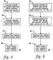
point processor 62 determines the light intensity due to the ambient and diffuse lighting effects, and the second floatingpoint processor 64 determines the light intensity due to specular lighting effects. On the other hand, in the case of multiple light sources (see Figure 6), as might for example be indicated by a "Begin Shaded Polygon (Multiple Light Sources)" datastream command, the first floating point processor 62' determines the light intensity (ambient, diffuse and specular) due to odd numbered light sources, while the second floating point processor 64' determines the light intensity (ambient, diffuse and specular) due to even numbered light sources. This is done to evenly divide the work to be performed between these two floating point processors and thereby avoid creating a bottleneck in the pipeline. - More particularly, when there is only one light source in the lighting model (see Figure 4);
- a. the first floating
point processor 62 calculates for each vertex the intensity due to ambient light and diffuse reflection, and then passes this value to the second floating point processor; - b. the second floating
point processor 64 calculates for each vertex the intensity due to specular reflection, and adds this result to the value passed to it by the first floating point processor; the second floating point processor then sends the data to the next floating point processor; - c. the third floating
point processor 66 performs a projection transformation and maps the coordinate data from viewing space to the screen space of the display system, passing this data to the next floating point processor; and - d. the fourth floating
point processor 68 does the calculations for depth cueing, color mapping and color clipping. - When there are multiple light sources in the lighting model (see Figure 6);
- a. the first floating point processor 62' calculates for each vertex the intensity due to ambient light, and diffuse and specular reflection of the odd numbered (#1, #3, #5, #7, etc.) light sources and then passes this value to the second floating point processor;
- b. the second floating point processor 64' calculates for each vertex the intensity due to ambient light, and diffuse and specular reflection of the even numbered (#2, #4, #6, #8, etc.) light sources and then adds this result to the one passed to it by the first floating point processor; it then passes this data to the third floating point processor;
- c. the third floating
point processor 66 performs a projection transformation and maps the coordinate data from viewing space to the screen space of the display system, passing this data to the next floating point processor; and - d. the fourth floating
point processor 68 does the calculations for depth cueing, color clipping and color mapping. - Figure 5 depicts an
alternate hardware embodiment 61 of the lighting model processing system of the present invention. In this alternate embodiment, the first and second stages of the system are each composed of three of the identical processors arranged in parallel. Each of these processors may be advantageously used to operate on a different color component. By way of example, a single light source modeling system is shown in Figure 5 wherein first stage floatingpoint processor 62R calculates ambient and diffuse lighting effects with regard to a red light component and passes the resulting red component intensity value to a second stage floatingpoint processor 64R which calculates the specular reflection effect on the red component and adds that to the value received from floatingpoint processor 62R. In a similar fashion, first stage floating point processor 62G and second stage floatingpoint processor 64G perform lighting model calculations on a green component, while first stage floating point processor 62B and second stage floatingpoint processor 64B perform the lighting model calculations on a blue component. The remainder of the system (i.e. the third and fourth stages) are unchanged. - For illustrative purposes, an RGB (red, green, blue) color model is used in this description. However, the principles of the invention are applicable to other color models as well, e.g. CMY (cyan, magenta, yellow), YIQ, HSV (hue, saturation, value), HLS (hue, lightness, saturation) etc. Similarly, the invention is applicable not only to light sources assumed to be at infinity but also to those at a finite distance, and to spot lighting and other lighting effects.
- Various specific implementations of the lighting model processing system of the present invention will be described hereinafter by reference to pseudo-code used to program the individual processors. The case of perspective projection (viewpoint at a finite distance) will be covered in detail. The simpler case of parallel projection (the viewpoint at infinity) will be covered briefly by mentioning the differences that occur when the viewpoint is at infinity. But first, a generalized lighting model taking into account the number of light sources, surface characteristics, and the positions and orientations of the surfaces and sources will be developed.
- The Viewing Coordinate System adopted here is the right-hand system. If we considered looking at a display screen, then the x-axis points to the right, y-axis points upward, and the z-axis points toward us. Therefore,
z-coordinate of data z-coordinate of viewpoint. - The following are the parameters of the lighting model with 1 light source:

- For a given vertex x,y,z and normal N = (a,,b,c) to the surface at that vertex, let:
L be the unit vector from the vertex to the light source, i.e. the direction to the point light source;
R be the direction of reflection; and
V be the direction of the viewpoint. - Then the shading color/intensity at the vertex is given by the sum of the following three terms: (we only include the R-component), the other two, G and B, can be expressed in a similar fashion)

- The light sources in the lighting model considered here are assumed at infinity. Their positions are specified by directional vectors of unit length; the viewpoint is at infinity.
- For multiple light sources, we have multiple terms for the second and third items.
- Assume there are j light sources (1 j =M) where M is the maximum number of light sources to be allowed in the particular implementation.
- The shading color/intensity at the vertex is given by the sum of the following three terms:
(we only include the R-component, the other two, G and B, can be expressed in similar fashion)
- A more detailed description of the derivation of the general lighting model can be found, for example, in Foley & Van Dam "Fundamentals of Interactive Computer Graphics" Addison-Wesley 1984, pp. 575-578.
- Specific exemplary implementations of the lighting model processing system of the present invention will now be presented. First, the lighting model calculations performed by the first and second processors are described for the following cases: single light source -- viewpoint at a finite distance; single light source -- viewpoint at an infinite distance, multiple light sources -- viewpoint at a finite distance, and multiple light sources -- viewpoint at an infinite distance. Then the mapping function performed by the third processor, and the depth cueing, color mapping and color clipping functions performed by the fourth processor (which functions are common to all of the above listed cases) are presented.
- In the following examples, software is presented in pseudocode, a commonly used notational scheme in which a single asterisk (*) indicates a multiplication operation, double asterisks (**) denotes a power term, the symbol (<) denotes "gets the value of", and in which a comment is bracketed between /* and */.
- This is the case of a single light source at a finite distance from the object with perspective projection (i.e. the viewpoint is at a finite distance from the object). The function of calculating the intensity of the vertex is divided among two floating point processors. The first floating point processor calculates the intensity of the ambient light and the diffuse term; and the second floating point processor calculates the intensity of the specular term.
- The input to the first floating point processor consists of six pieces of data:
x,y,z coordinates of the vertex; and
the coordinates of the normal to the surface at the vertex, i.e. a, b, c. - The output of the first floating point processor to the second floating point processor for each vertex consists of nine words:
x, y, z coordinates of the vertex;
the components of the reflection direction rx, ry, rz; and
the partial intensity values (ambient plus diffuse effects) for R, G, and B. - The pseudocode for the first and second floating point processors, for this case, follows:
Procedure Intensity_Single 12 (viewing at a finite distance)


- The simpler case where the viewpoint is at infinity (parallel projection) differs from the above described case where the viewpoint is at a finite distance, only in the treatment of the reflection vector during the calculation of the light due to specular reflection. In the case where the viewpoint is at infinity, only the z-component is used since the viewpoint direction is given by (0,0,1) in a parallel projection case.
- In this example, the maximum number of light sources is assumed to be 10. The function of calculating the intensity for each vertex is divided among two floating point processors. The first floating point processor processes the color intensity due to light source #1, #3, #5, etc., and the second floating point processor processes the color intensity due to light source #2, #4, #6, etc.
- The pseudocode for the first floating point processor, for this case, follows:
Procedure Intensity_Multiple 12 (viewpoint at a finite distance)


- The pseudocode for the second floating point processor in this case (multiple light sources -- viewpoint at a finite distance) is identical to that listed above for the first floating point processor, with the following differences:
- 1. The reflection direction (direction to the viewpoint) calculated by the first floating point processor is passed as an input to the second floating point processor so that the second floating point processor does not need to calculate it.
- 2. The light contributions due to the even-numbered light sources (#2, #4, #6, etc.) are computed rather than those due to the odd-numbered light sources; and
- 3. The contributions due to the even-numbered light sources are added to the contributions of the odd-numbered light sources (which were passed from the first floating point processor to the second as inputs) to obtain the total light intensity at each vertex.
- Once again, the case where the viewpoint is at infinity (parallel projection) differs from the case where the viewpoint is at a finite distance, only in the treatment of the reflection vector during the calculation of the light due to specular reflection. In the case where the viewpoint is at infinity, only the z-component is used since the viewpoint direction is given by (0, 0, 1) in the parallel projection case.
- This stage of the pipeline performs the following two steps on each polygon vertex in the order listed:
- 1. An input vertex is transformed from the 3D viewing space to another 3D space according to a "projection" transformation that has the following characteristics:
- a. The x and y coordinates produced by the transformation are the projection of the vertex onto the viewpoint plane;
- b. The transformation preserves planarity (i.e., applying the transformation to vertices that are coplanar in the 3D viewing space yields vertices that are coplanar in the output 3D space.
- 2. The transformed vertex is then mapped to the viewport by means of a "mapping" transformation.
- In the case of perspective projection (viewpoint at a finite distance from the object), the projection transformation is accomplished by means of the following formulae:

- In the case of parallel projection (viewpoint at infinity), the viewing space coordinate values themselves are used as the projection values:
Xproj = x
Yproj = y
Zproj = z. - Whether parallel or perspective, the projection transformation is followed by the mapping transformation, which is accomplished by means of the following formulae:
Xscreen ←- XVmin + Rx*(X - XCmin)
Yscreen ←- YVmin + Ry*(Y - YCmin)
where XVmin is the left boundary of the viewport (the area of the screen which will be used to display the image), XCmin is the left boundary of the clipping volume (the region of viewing space which will be mapped to the viewport), YVmin is the lower boundary of the viewport, YCmin is the lower boundary of the clipping volume, and Rx and Ry are the X and Y ratios of the size of the viewport to the size of the clipping volume. - Pseudocode for the projection and mapping procedure follows:
Procedure Projection and Mapping


- The following conceptual steps are implemented in this processor:
- Depth cueing (the changing of the light intensity at a point as a function of the point's distance from the viewer);
- Colour mapping (the process by which the light intensities calculated as a result of the lighting and depth cueing processes are mapped to the dynamic colour capabilities of the subsequent display system); and
- Colour clipping (the process by which intensities that exceed the maximum intensity supported by the dynamic colour capabilities of the display system are replaced with the maximum intensity value). - In this process, the RGB intensities calculated by the lighting model at a vertex are blended with a specified colour value as a visual cue indicating to the workstation user which portions of the image on the screen are furthest from the viewpoint. This is done by means of a mixing function which varies the output colour intensity as a function of the z coordinate of the vertex:
Ci = w*Intensi + (1-w)*Cdi
Where:
- Intensi is the component of the input colour at the vertex;
- Cdi is the component of the colour intensity with which blending is done; and
- Ci is the component of the output colour intensity at the vertex;
for i = R, G, and B, and
- Pf is the z value of the front reference plane;
- Pb is the z value of the back reference plane;
- Sf is the front scale factor;
- Sb is the back scale factor; and
- w, the mixing function variable, is defined as a function of Zproj, the z value created by the projection and mapping stage, according to the following formulae:
w = Sb; Zproj <Pb - The colour intensities calculated by the lighting and depth cueing processes are independent of the dynamic range of colour intensities that can be displayed by the display hardware subsequent in the system. In order to couple the lighting model calculation stages to the display hardware following it in the graphics workstation, this step applies a linear transformation to each individual colour component to match the dynamic colour range available in the display hardware. The new colour values C'i (i = R, G, and B) are obtained by means of the formulae:
C'i = ai Ci + bi (i = R, G, B)
where the ai's and bi's are the colour mapping parameters appropriate for the display hardware. - Even after the mapping step, the intensities calculated by the lighting stage may range higher than the maximum intensity supported by the display hardware. The purpose of the colour clipping step is to make sure the colour intensities passed to the display hardware do not exceed the maximum allowed value. This removes saturation problems caused by large colour values created during the lighting caluclation stages. The new colour values, C"i (i + R, G, and B), are given by the formulae:
C"i = MIN(Bhi, C'i) (i = R, G, B)
where Bhi is the maximum allowable value for colour component i, and C'i is the output colour component from the colour mapping step. In addition, this step converts the floating point representation of the output colour intensity to the integer representation needed by the display hardware. - Since the formulae used in the depth cueing and colour mapping steps are linear equations, they can be combined into one equation to reduce the number of calculations that must be performed in this stage of the pipeline. To this end, the following parameters of the combined equation are calculated in advance, that is, at the time that the control parameters for these steps are specified:
Qfi = ai*Sf
Qbi = ai*Sb
Ai = ai*F
Bi = ai(Sb - F*Pb)
hi = ai*Cdi + bi
for i = R, G, and B, where
- Having calculated the preceding parameters in advance, the following sequence of operations is performed:
- 1. Compute qi as a linear function of x, the depth cueing parameters, and the display hardware parameters:

- 2. Compute the mapped depth-cued colour intensity C'i as a function of the input colour Ci and previously computed parameters qi and hi:
C'i = qi (Ci - Cdi) + hi (i = R, G, B) - 3. Clip the mapped depth-cued colour intensity C'i and convert it to integer representation for the subsequent display hardware's use:
C"i = TRUNC(MIN(Bhi,C'i)) (i = R, G, B)
where the function TRUNC for TRUNCation) converts the floating point value to integer representation. - Pseudocode suitable for implementing the depth cueing, colour mapping and colour clipping procedures follows:
Procedure Depth_Colour


- From the preceding detailed description it will be apparent that a new lighting model processing system has been developed which exhibits high throughput, affords improved interactivity and higher image quality, and fulfills all of the other objects set forth hereinabove. Although various specific embodiments have been depicted and described, it will be evident to those skilled in this art that numerous modifications, substitutions, additions and other changes may be made without departing from the principles of the invention, the scope of which is defined by the claims appended hereto.
Claims (10)
a pipeline arrangement of multiple identical floating point processors, which arrangement receives data representing coordinates in viewing space of vertices of a polygon and a normal at each of the vertices of the polygon, and calculates therefrom coordinates on the viewing screen of the vertices, and screen colour intensity values associated with each of said vertices based upon a specified lighting model.
at least one processor for calculating for each of said vertices a first set of colour intensity values due to ambient lighting and diffuse and specular reflection effects;
a second processor for receiving and processing said first set of colour intensity values to provide for depth cueing, colour mapping and colour clipping; and
a third processor for performing a projection transformation and for mapping the coordinates of each of the vertices from viewing space to screen space.
an input FIFO, an output FIFO, floating point arithmetic processing means connected between said input FIFO and output FIFO, data storage means for interfacing with said arithmetic processing means, control logic and control program storage means, and sequencer means for controlling the operation of said arithmetic processing means and data storage means in accordance with said control logic and control program.
said data storage means comprises a bank of registers for storing data; and
said arithmetic processing means comprises a floating point multiplier, means for calculating inverses and square roots, and a floating point adder, the adder being connected to said multiplier in such a way as to serve as an accumulator for the multiplier.
wherein the pipeline arrangement of multiple processing stages receives data representing x, y and z coordinates in viewing space of vertices of a polygon and x, y and z components of a normal at each of the vertices of the polygon, and calculates therefrom x and y coordinates on the viewing screen of the vertices and screen colour intensity values associated with each of said vertices based upon a specified lighting model.
first and second processing stages for jointly calculating vertex intensity values due to ambient light and diffuse and specular reflection;
a third processing stage for receiving the intensity values jointly calculated by said first and second processing stages and for further processing said intensity values to provide for depth cueing,
a fourth processing stage for mapping vertices onto a viewing screen,
said third processing stage further comprises means for performing colour mapping and colour clipping,
said first and second processing stages are selectively programmable to accommodate a single light source model and a multiple light source model, with the intensity value calculations being partitioned so as to maintain a computational work load balance between said first and second processing stages, and
wherein the first processing stage calculates ambient lighting and diffuse reflection effects, and the second processing stage calculates specular reflection effects when said first and second processing stages are programmed to accommodate a single light source model.
providing multiple identical floating point processors capable of performing such lighting model calculations;
connecting and operating said multiple processors in a pipeline arrangement;
partitioning the lighting model calculations among said multiple processors so as to substantially balance computational workload between said processors,
said partitioning step comprises dynamically partitioning the lighting model calculations in a fashion designed to maintain substantial computational workload balance between said processors irrespective of the number of light sources being modeled.
Applications Claiming Priority (2)
| Application Number | Priority Date | Filing Date | Title |
|---|---|---|---|
| US07/115,467 US4866637A (en) | 1987-10-30 | 1987-10-30 | Pipelined lighting model processing system for a graphics workstation's shading function |
| US115467 | 1993-09-01 |
Publications (3)
| Publication Number | Publication Date |
|---|---|
| EP0314341A2 true EP0314341A2 (en) | 1989-05-03 |
| EP0314341A3 EP0314341A3 (en) | 1991-07-24 |
| EP0314341B1 EP0314341B1 (en) | 1995-03-15 |
Family
ID=22361599
Family Applications (1)
| Application Number | Title | Priority Date | Filing Date |
|---|---|---|---|
| EP88309573A Expired - Lifetime EP0314341B1 (en) | 1987-10-30 | 1988-10-13 | Computer graphic apparatus for processing lighting model information |
Country Status (5)
| Country | Link |
|---|---|
| US (1) | US4866637A (en) |
| EP (1) | EP0314341B1 (en) |
| JP (1) | JPH0731741B2 (en) |
| CA (1) | CA1304824C (en) |
| DE (1) | DE3853336T2 (en) |
Cited By (8)
| Publication number | Priority date | Publication date | Assignee | Title |
|---|---|---|---|---|
| EP0489552A2 (en) * | 1990-12-03 | 1992-06-10 | I.G.E. Medical Systems Limited | Image processing system |
| FR2670924A1 (en) * | 1990-12-20 | 1992-06-26 | Gen Electric | Simulation of the illumination of a light source in computer image generation |
| GB2271257A (en) * | 1992-10-02 | 1994-04-06 | Canon Res Ct Europe Ltd | Processing image data |
| WO1995006298A1 (en) * | 1993-08-24 | 1995-03-02 | Taligent, Inc. | Object oriented shading |
| EP0817010A2 (en) * | 1996-07-02 | 1998-01-07 | Sun Microsystems, Inc. | Floating point processor for a three-dimensional graphics accelerator |
| EP0837429A2 (en) * | 1996-10-15 | 1998-04-22 | Lockhead Martin Corporation | Apparatus and method for simulating specular reflection in a computer graphics/imaging system |
| EP0933729A2 (en) * | 1998-02-03 | 1999-08-04 | Sun Microsystems, Inc. | Three-dimensional graphics accelerator |
| US8683182B2 (en) | 1995-08-16 | 2014-03-25 | Microunity Systems Engineering, Inc. | System and apparatus for group floating-point inflate and deflate operations |
Families Citing this family (124)
| Publication number | Priority date | Publication date | Assignee | Title |
|---|---|---|---|---|
| GB9405914D0 (en) * | 1994-03-24 | 1994-05-11 | Discovision Ass | Video decompression |
| US5222203A (en) * | 1989-01-20 | 1993-06-22 | Daikin Industries, Ltd. | Method and apparatus for displaying translucent surface |
| JP2774627B2 (en) * | 1989-12-28 | 1998-07-09 | 株式会社日立製作所 | Image display method and apparatus |
| SE464265B (en) * | 1990-01-10 | 1991-03-25 | Stefan Blixt | Graphics Processor |
| DE69129995T2 (en) * | 1990-01-23 | 1998-12-24 | Hewlett Packard Co | Decentralized processing device and method for use in global reproduction |
| JPH0476680A (en) * | 1990-05-14 | 1992-03-11 | Mitsubishi Electric Corp | Graphic display method for rotary body |
| JPH04122544A (en) * | 1990-05-14 | 1992-04-23 | Mitsubishi Electric Corp | Cutting simulation method for lathe |
| EP0459761A3 (en) * | 1990-05-31 | 1993-07-14 | Hewlett-Packard Company | Three dimensional computer graphics employing ray tracking to compute form factors in radiosity |
| US5253339A (en) * | 1990-07-26 | 1993-10-12 | Sun Microsystems, Inc. | Method and apparatus for adaptive Phong shading |
| TW225595B (en) * | 1991-09-03 | 1994-06-21 | Gen Electric | |
| US5706415A (en) * | 1991-12-20 | 1998-01-06 | Apple Computer, Inc. | Method and apparatus for distributed interpolation of pixel shading parameter values |
| US5388841A (en) * | 1992-01-30 | 1995-02-14 | A/N Inc. | External memory system having programmable graphics processor for use in a video game system or the like |
| JP3102031B2 (en) * | 1992-03-31 | 2000-10-23 | セイコーエプソン株式会社 | 3D color image generation system and method using simulated light source |
| US6079009A (en) * | 1992-06-30 | 2000-06-20 | Discovision Associates | Coding standard token in a system compromising a plurality of pipeline stages |
| US6067417A (en) * | 1992-06-30 | 2000-05-23 | Discovision Associates | Picture start token |
| US7095783B1 (en) | 1992-06-30 | 2006-08-22 | Discovision Associates | Multistandard video decoder and decompression system for processing encoded bit streams including start codes and methods relating thereto |
| US6330665B1 (en) | 1992-06-30 | 2001-12-11 | Discovision Associates | Video parser |
| US6263422B1 (en) | 1992-06-30 | 2001-07-17 | Discovision Associates | Pipeline processing machine with interactive stages operable in response to tokens and system and methods relating thereto |
| US5768561A (en) * | 1992-06-30 | 1998-06-16 | Discovision Associates | Tokens-based adaptive video processing arrangement |
| US5809270A (en) * | 1992-06-30 | 1998-09-15 | Discovision Associates | Inverse quantizer |
| US6034674A (en) * | 1992-06-30 | 2000-03-07 | Discovision Associates | Buffer manager |
| US5842033A (en) | 1992-06-30 | 1998-11-24 | Discovision Associates | Padding apparatus for passing an arbitrary number of bits through a buffer in a pipeline system |
| US5828907A (en) | 1992-06-30 | 1998-10-27 | Discovision Associates | Token-based adaptive video processing arrangement |
| DE69229338T2 (en) * | 1992-06-30 | 1999-12-16 | Discovision Ass | Data pipeline system |
| US6417859B1 (en) | 1992-06-30 | 2002-07-09 | Discovision Associates | Method and apparatus for displaying video data |
| US6112017A (en) * | 1992-06-30 | 2000-08-29 | Discovision Associates | Pipeline processing machine having a plurality of reconfigurable processing stages interconnected by a two-wire interface bus |
| US6047112A (en) * | 1992-06-30 | 2000-04-04 | Discovision Associates | Technique for initiating processing of a data stream of encoded video information |
| EP0578950A3 (en) * | 1992-07-15 | 1995-11-22 | Ibm | Method and apparatus for converting floating-point pixel values to byte pixel values by table lookup |
| US5357599A (en) * | 1992-07-30 | 1994-10-18 | International Business Machines Corporation | Method and apparatus for rendering polygons |
| US5821940A (en) * | 1992-08-03 | 1998-10-13 | Ball Corporation | Computer graphics vertex index cache system for polygons |
| US5315701A (en) * | 1992-08-07 | 1994-05-24 | International Business Machines Corporation | Method and system for processing graphics data streams utilizing scalable processing nodes |
| TW241196B (en) * | 1993-01-15 | 1995-02-21 | Du Pont | |
| US5402533A (en) * | 1993-04-22 | 1995-03-28 | Apple Computer, Inc. | Method and apparatus for approximating a signed value between two endpoint values in a three-dimensional image rendering device |
| US5606650A (en) * | 1993-04-22 | 1997-02-25 | Apple Computer, Inc. | Method and apparatus for storage and retrieval of a texture map in a graphics display system |
| IL109462A0 (en) * | 1993-04-30 | 1994-07-31 | Scitex Corp Ltd | Method for generating artificial shadow |
| US5583974A (en) * | 1993-05-10 | 1996-12-10 | Apple Computer, Inc. | Computer graphics system having high performance multiple layer Z-buffer |
| WO1994027240A1 (en) * | 1993-05-10 | 1994-11-24 | Apple Computer, Inc. | Computer graphics system having high performance multiple layer z-buffer |
| US5974189A (en) * | 1993-05-24 | 1999-10-26 | Eastman Kodak Company | Method and apparatus for modifying electronic image data |
| DE69418646T2 (en) * | 1993-06-04 | 2000-06-29 | Sun Microsystems Inc | Floating point processor for a high-performance three-dimensional graphics accelerator |
| US5805914A (en) * | 1993-06-24 | 1998-09-08 | Discovision Associates | Data pipeline system and data encoding method |
| US5613052A (en) * | 1993-09-02 | 1997-03-18 | International Business Machines Corporation | Method and apparatus for clipping and determining color factors for polygons |
| US5742292A (en) * | 1993-10-29 | 1998-04-21 | Kabushiki Kaisha Toshiba | System and method for realistically displaying images indicating the effects of lighting on an object in three dimensional space |
| CA2145363C (en) * | 1994-03-24 | 1999-07-13 | Anthony Mark Jones | Ram interface |
| CA2145365C (en) * | 1994-03-24 | 1999-04-27 | Anthony M. Jones | Method for accessing banks of dram |
| CA2145379C (en) * | 1994-03-24 | 1999-06-08 | William P. Robbins | Method and apparatus for addressing memory |
| US5808627A (en) * | 1994-04-22 | 1998-09-15 | Apple Computer, Inc. | Method and apparatus for increasing the speed of rendering of objects in a display system |
| GB9417138D0 (en) | 1994-08-23 | 1994-10-12 | Discovision Ass | Data rate conversion |
| US5835096A (en) * | 1995-03-24 | 1998-11-10 | 3D Labs | Rendering system using 3D texture-processing hardware for accelerated 2D rendering |
| US6025853A (en) * | 1995-03-24 | 2000-02-15 | 3Dlabs Inc. Ltd. | Integrated graphics subsystem with message-passing architecture |
| US5798770A (en) * | 1995-03-24 | 1998-08-25 | 3Dlabs Inc. Ltd. | Graphics rendering system with reconfigurable pipeline sequence |
| US5764243A (en) * | 1995-03-24 | 1998-06-09 | 3Dlabs Inc. Ltd. | Rendering architecture with selectable processing of multi-pixel spans |
| US5764228A (en) * | 1995-03-24 | 1998-06-09 | 3Dlabs Inc., Ltd. | Graphics pre-processing and rendering system |
| US5717715A (en) * | 1995-06-07 | 1998-02-10 | Discovision Associates | Signal processing apparatus and method |
| JPH096424A (en) * | 1995-06-19 | 1997-01-10 | Mitsubishi Electric Corp | Cad and cam device and working simulation method |
| US6111584A (en) * | 1995-12-18 | 2000-08-29 | 3Dlabs Inc. Ltd. | Rendering system with mini-patch retrieval from local texture storage |
| US5739819A (en) * | 1996-02-05 | 1998-04-14 | Scitex Corporation Ltd. | Method and apparatus for generating an artificial shadow in a two dimensional color image |
| DE19606357A1 (en) * | 1996-02-12 | 1997-08-14 | Gmd Gmbh | Image processing method for the representation of reflecting objects and associated device |
| JP3226153B2 (en) * | 1996-03-18 | 2001-11-05 | シャープ株式会社 | Multimedia data display device |
| JP3387750B2 (en) * | 1996-09-02 | 2003-03-17 | 株式会社リコー | Shading processing equipment |
| US6016149A (en) * | 1997-06-30 | 2000-01-18 | Sun Microsystems, Inc. | Lighting unit for a three-dimensional graphics accelerator with improved processing of multiple light sources |
| US6650327B1 (en) | 1998-06-16 | 2003-11-18 | Silicon Graphics, Inc. | Display system having floating point rasterization and floating point framebuffering |
| US6977649B1 (en) | 1998-11-23 | 2005-12-20 | 3Dlabs, Inc. Ltd | 3D graphics rendering with selective read suspend |
| US6417858B1 (en) * | 1998-12-23 | 2002-07-09 | Microsoft Corporation | Processor for geometry transformations and lighting calculations |
| US6181352B1 (en) | 1999-03-22 | 2001-01-30 | Nvidia Corporation | Graphics pipeline selectively providing multiple pixels or multiple textures |
| US6333744B1 (en) * | 1999-03-22 | 2001-12-25 | Nvidia Corporation | Graphics pipeline including combiner stages |
| US6611265B1 (en) | 1999-10-18 | 2003-08-26 | S3 Graphics Co., Ltd. | Multi-stage fixed cycle pipe-lined lighting equation evaluator |
| US6452600B1 (en) | 1999-10-28 | 2002-09-17 | Nintendo Co., Ltd. | Graphics system interface |
| US6618048B1 (en) | 1999-10-28 | 2003-09-09 | Nintendo Co., Ltd. | 3D graphics rendering system for performing Z value clamping in near-Z range to maximize scene resolution of visually important Z components |
| US6411301B1 (en) | 1999-10-28 | 2002-06-25 | Nintendo Co., Ltd. | Graphics system interface |
| US6597357B1 (en) * | 1999-12-20 | 2003-07-22 | Microsoft Corporation | Method and system for efficiently implementing two sided vertex lighting in hardware |
| US6859862B1 (en) | 2000-04-07 | 2005-02-22 | Nintendo Co., Ltd. | Method and apparatus for software management of on-chip cache |
| US6857061B1 (en) | 2000-04-07 | 2005-02-15 | Nintendo Co., Ltd. | Method and apparatus for obtaining a scalar value directly from a vector register |
| US6664963B1 (en) * | 2000-05-31 | 2003-12-16 | Nvidia Corporation | System, method and computer program product for programmable shading using pixel shaders |
| US6724394B1 (en) | 2000-05-31 | 2004-04-20 | Nvidia Corporation | Programmable pixel shading architecture |
| US7119813B1 (en) | 2000-06-02 | 2006-10-10 | Nintendo Co., Ltd. | Variable bit field encoding |
| US6788302B1 (en) | 2000-08-03 | 2004-09-07 | International Business Machines Corporation | Partitioning and load balancing graphical shape data for parallel applications |
| US6700586B1 (en) | 2000-08-23 | 2004-03-02 | Nintendo Co., Ltd. | Low cost graphics with stitching processing hardware support for skeletal animation |
| US7184059B1 (en) | 2000-08-23 | 2007-02-27 | Nintendo Co., Ltd. | Graphics system with copy out conversions between embedded frame buffer and main memory |
| US7034828B1 (en) | 2000-08-23 | 2006-04-25 | Nintendo Co., Ltd. | Recirculating shade tree blender for a graphics system |
| US7002591B1 (en) | 2000-08-23 | 2006-02-21 | Nintendo Co., Ltd. | Method and apparatus for interleaved processing of direct and indirect texture coordinates in a graphics system |
| US6580430B1 (en) | 2000-08-23 | 2003-06-17 | Nintendo Co., Ltd. | Method and apparatus for providing improved fog effects in a graphics system |
| US7538772B1 (en) | 2000-08-23 | 2009-05-26 | Nintendo Co., Ltd. | Graphics processing system with enhanced memory controller |
| US6707458B1 (en) | 2000-08-23 | 2004-03-16 | Nintendo Co., Ltd. | Method and apparatus for texture tiling in a graphics system |
| US7196710B1 (en) | 2000-08-23 | 2007-03-27 | Nintendo Co., Ltd. | Method and apparatus for buffering graphics data in a graphics system |
| US6606689B1 (en) | 2000-08-23 | 2003-08-12 | Nintendo Co., Ltd. | Method and apparatus for pre-caching data in audio memory |
| US6999100B1 (en) | 2000-08-23 | 2006-02-14 | Nintendo Co., Ltd. | Method and apparatus for anti-aliasing in a graphics system |
| US6636214B1 (en) | 2000-08-23 | 2003-10-21 | Nintendo Co., Ltd. | Method and apparatus for dynamically reconfiguring the order of hidden surface processing based on rendering mode |
| US6811489B1 (en) | 2000-08-23 | 2004-11-02 | Nintendo Co., Ltd. | Controller interface for a graphics system |
| US6980218B1 (en) | 2000-08-23 | 2005-12-27 | Nintendo Co., Ltd. | Method and apparatus for efficient generation of texture coordinate displacements for implementing emboss-style bump mapping in a graphics rendering system |
| US7134960B1 (en) | 2000-08-23 | 2006-11-14 | Nintendo Co., Ltd. | External interfaces for a 3D graphics system |
| US6664962B1 (en) | 2000-08-23 | 2003-12-16 | Nintendo Co., Ltd. | Shadow mapping in a low cost graphics system |
| US6609977B1 (en) | 2000-08-23 | 2003-08-26 | Nintendo Co., Ltd. | External interfaces for a 3D graphics system |
| US6867781B1 (en) | 2000-08-23 | 2005-03-15 | Nintendo Co., Ltd. | Graphics pipeline token synchronization |
| US6664958B1 (en) | 2000-08-23 | 2003-12-16 | Nintendo Co., Ltd. | Z-texturing |
| US6639595B1 (en) | 2000-08-23 | 2003-10-28 | Nintendo Co., Ltd. | Achromatic lighting in a graphics system and method |
| US6937245B1 (en) | 2000-08-23 | 2005-08-30 | Nintendo Co., Ltd. | Graphics system with embedded frame buffer having reconfigurable pixel formats |
| US6825851B1 (en) | 2000-08-23 | 2004-11-30 | Nintendo Co., Ltd. | Method and apparatus for environment-mapped bump-mapping in a graphics system |
| US6697074B2 (en) | 2000-11-28 | 2004-02-24 | Nintendo Co., Ltd. | Graphics system interface |
| FR2826769B1 (en) * | 2001-06-29 | 2003-09-05 | Thales Sa | METHOD FOR DISPLAYING MAPPING INFORMATION ON AIRCRAFT SCREEN |
| US6781594B2 (en) * | 2001-08-21 | 2004-08-24 | Sony Computer Entertainment America Inc. | Method for computing the intensity of specularly reflected light |
| US7003588B1 (en) | 2001-08-22 | 2006-02-21 | Nintendo Co., Ltd. | Peripheral devices for a video game system |
| WO2003032253A2 (en) * | 2001-10-10 | 2003-04-17 | Sony Computer Entertainment America Inc. | System and method for environment mapping |
| US7451457B2 (en) | 2002-04-15 | 2008-11-11 | Microsoft Corporation | Facilitating interaction between video renderers and graphics device drivers |
| US7219352B2 (en) | 2002-04-15 | 2007-05-15 | Microsoft Corporation | Methods and apparatuses for facilitating processing of interlaced video images for progressive video displays |
| US7308139B2 (en) * | 2002-07-12 | 2007-12-11 | Chroma Energy, Inc. | Method, system, and apparatus for color representation of seismic data and associated measurements |
| US7006090B2 (en) * | 2003-02-07 | 2006-02-28 | Crytek Gmbh | Method and computer program product for lighting a computer graphics image and a computer |
| US7106326B2 (en) * | 2003-03-03 | 2006-09-12 | Sun Microsystems, Inc. | System and method for computing filtered shadow estimates using reduced bandwidth |
| JP2005057738A (en) * | 2003-07-18 | 2005-03-03 | Canon Inc | Signal processing apparatus, signal processing method, and program |
| US7643675B2 (en) * | 2003-08-01 | 2010-01-05 | Microsoft Corporation | Strategies for processing image information using a color information data structure |
| US7139002B2 (en) * | 2003-08-01 | 2006-11-21 | Microsoft Corporation | Bandwidth-efficient processing of video images |
| US7158668B2 (en) | 2003-08-01 | 2007-01-02 | Microsoft Corporation | Image processing using linear light values and other image processing improvements |
| US8133115B2 (en) | 2003-10-22 | 2012-03-13 | Sony Computer Entertainment America Llc | System and method for recording and displaying a graphical path in a video game |
| US20060071933A1 (en) | 2004-10-06 | 2006-04-06 | Sony Computer Entertainment Inc. | Application binary interface for multi-pass shaders |
| US7636126B2 (en) | 2005-06-22 | 2009-12-22 | Sony Computer Entertainment Inc. | Delay matching in audio/video systems |
| US7965859B2 (en) | 2006-05-04 | 2011-06-21 | Sony Computer Entertainment Inc. | Lighting control of a user environment via a display device |
| US7880746B2 (en) | 2006-05-04 | 2011-02-01 | Sony Computer Entertainment Inc. | Bandwidth management through lighting control of a user environment via a display device |
| US7940266B2 (en) * | 2006-10-13 | 2011-05-10 | International Business Machines Corporation | Dynamic reallocation of processing cores for balanced ray tracing graphics workload |
| WO2008060948A2 (en) * | 2006-11-10 | 2008-05-22 | Sandbridge Technologies, Inc. | Method and system for parallelization of pipelined computations |
| US8922565B2 (en) * | 2007-11-30 | 2014-12-30 | Qualcomm Incorporated | System and method for using a secondary processor in a graphics system |
| US8081019B2 (en) * | 2008-11-21 | 2011-12-20 | Flextronics Ap, Llc | Variable PFC and grid-tied bus voltage control |
| US10786736B2 (en) | 2010-05-11 | 2020-09-29 | Sony Interactive Entertainment LLC | Placement of user information in a game space |
| US9342817B2 (en) | 2011-07-07 | 2016-05-17 | Sony Interactive Entertainment LLC | Auto-creating groups for sharing photos |
| CN105023249B (en) * | 2015-06-26 | 2017-11-17 | 清华大学深圳研究生院 | Bloom image repair method and device based on light field |
| US11756254B2 (en) * | 2020-12-08 | 2023-09-12 | Nvidia Corporation | Light importance caching using spatial hashing in real-time ray tracing applications |
Citations (2)
| Publication number | Priority date | Publication date | Assignee | Title |
|---|---|---|---|---|
| US4343037A (en) * | 1979-06-15 | 1982-08-03 | Redifon Simulation Limited | Visual display systems of the computer generated image type |
| EP0193151A2 (en) * | 1985-02-26 | 1986-09-03 | Sony Corporation | Method of displaying image |
Family Cites Families (6)
| Publication number | Priority date | Publication date | Assignee | Title |
|---|---|---|---|---|
| JPS5513582A (en) * | 1978-07-13 | 1980-01-30 | Sanyo Electric Co Ltd | Color television receiver |
| US4241341A (en) * | 1979-03-05 | 1980-12-23 | Thorson Mark R | Apparatus for scan conversion |
| US4646075A (en) * | 1983-11-03 | 1987-02-24 | Robert Bosch Corporation | System and method for a data processing pipeline |
| US4658247A (en) * | 1984-07-30 | 1987-04-14 | Cornell Research Foundation, Inc. | Pipelined, line buffered real-time color graphics display system |
| JPH0746391B2 (en) * | 1984-09-14 | 1995-05-17 | 株式会社日立製作所 | Graphic seeding device |
| US4737921A (en) * | 1985-06-03 | 1988-04-12 | Dynamic Digital Displays, Inc. | Three dimensional medical image display system |
-
1987
- 1987-10-30 US US07/115,467 patent/US4866637A/en not_active Expired - Fee Related
-
1988
- 1988-10-13 EP EP88309573A patent/EP0314341B1/en not_active Expired - Lifetime
- 1988-10-13 DE DE3853336T patent/DE3853336T2/en not_active Expired - Fee Related
- 1988-10-27 CA CA000581529A patent/CA1304824C/en not_active Expired - Lifetime
- 1988-10-28 JP JP63271091A patent/JPH0731741B2/en not_active Expired - Lifetime
Patent Citations (2)
| Publication number | Priority date | Publication date | Assignee | Title |
|---|---|---|---|---|
| US4343037A (en) * | 1979-06-15 | 1982-08-03 | Redifon Simulation Limited | Visual display systems of the computer generated image type |
| EP0193151A2 (en) * | 1985-02-26 | 1986-09-03 | Sony Corporation | Method of displaying image |
Cited By (13)
| Publication number | Priority date | Publication date | Assignee | Title |
|---|---|---|---|---|
| EP0489552A2 (en) * | 1990-12-03 | 1992-06-10 | I.G.E. Medical Systems Limited | Image processing system |
| EP0489552A3 (en) * | 1990-12-03 | 1992-12-30 | I.G.E. Medical Systems Limited | Image processing system |
| FR2670924A1 (en) * | 1990-12-20 | 1992-06-26 | Gen Electric | Simulation of the illumination of a light source in computer image generation |
| GB2271257A (en) * | 1992-10-02 | 1994-04-06 | Canon Res Ct Europe Ltd | Processing image data |
| WO1995006298A1 (en) * | 1993-08-24 | 1995-03-02 | Taligent, Inc. | Object oriented shading |
| US8769248B2 (en) | 1995-08-16 | 2014-07-01 | Microunity Systems Engineering, Inc. | System and apparatus for group floating-point inflate and deflate operations |
| US8683182B2 (en) | 1995-08-16 | 2014-03-25 | Microunity Systems Engineering, Inc. | System and apparatus for group floating-point inflate and deflate operations |
| EP0817010A3 (en) * | 1996-07-02 | 2001-12-19 | Sun Microsystems, Inc. | Floating point processor for a three-dimensional graphics accelerator |
| EP0817010A2 (en) * | 1996-07-02 | 1998-01-07 | Sun Microsystems, Inc. | Floating point processor for a three-dimensional graphics accelerator |
| EP0837429A3 (en) * | 1996-10-15 | 1998-12-09 | Lockhead Martin Corporation | Apparatus and method for simulating specular reflection in a computer graphics/imaging system |
| EP0837429A2 (en) * | 1996-10-15 | 1998-04-22 | Lockhead Martin Corporation | Apparatus and method for simulating specular reflection in a computer graphics/imaging system |
| EP0933729A2 (en) * | 1998-02-03 | 1999-08-04 | Sun Microsystems, Inc. | Three-dimensional graphics accelerator |
| EP0933729A3 (en) * | 1998-02-03 | 2002-05-08 | Sun Microsystems, Inc. | Three-dimensional graphics accelerator |
Also Published As
| Publication number | Publication date |
|---|---|
| CA1304824C (en) | 1992-07-07 |
| DE3853336T2 (en) | 1995-09-28 |
| DE3853336D1 (en) | 1995-04-20 |
| JPH01163884A (en) | 1989-06-28 |
| EP0314341A3 (en) | 1991-07-24 |
| EP0314341B1 (en) | 1995-03-15 |
| US4866637A (en) | 1989-09-12 |
| JPH0731741B2 (en) | 1995-04-10 |
Similar Documents
| Publication | Publication Date | Title |
|---|---|---|
| EP0314341A2 (en) | Computer graphic apparatus for processing lighting model information | |
| US6333744B1 (en) | Graphics pipeline including combiner stages | |
| US6664963B1 (en) | System, method and computer program product for programmable shading using pixel shaders | |
| US8144158B2 (en) | Display system having floating point rasterization and floating point framebuffering | |
| US5185856A (en) | Arithmetic and logic processing unit for computer graphics system | |
| US6624823B2 (en) | Graphics system configured to determine triangle orientation by octant identification and slope comparison | |
| US5553208A (en) | Image synthesizing system having a field buffer unit that stores texture coordinates | |
| US5230039A (en) | Texture range controls for improved texture mapping | |
| US5268995A (en) | Method for executing graphics Z-compare and pixel merge instructions in a data processor | |
| US8130227B2 (en) | Distributed antialiasing in a multiprocessor graphics system | |
| US6525723B1 (en) | Graphics system which renders samples into a sample buffer and generates pixels in response to stored samples at different rates | |
| US6496186B1 (en) | Graphics system having a super-sampled sample buffer with generation of output pixels using selective adjustment of filtering for reduced artifacts | |
| EP0622747A2 (en) | Method and apparatus for an adaptive texture mapping controller | |
| US5877769A (en) | Image processing apparatus and method | |
| US6806886B1 (en) | System, method and article of manufacture for converting color data into floating point numbers in a computer graphics pipeline | |
| US6489956B1 (en) | Graphics system having a super-sampled sample buffer with generation of output pixels using selective adjustment of filtering for implementation of display effects | |
| GB2226219A (en) | Method for three-dimensional clip checking for computer graphics | |
| US6778188B2 (en) | Reconfigurable hardware filter for texture mapping and image processing | |
| US7116333B1 (en) | Data retrieval method and system | |
| EP1155385B1 (en) | Graphics system having a super-sampled sample buffer with efficient storage of sample position information | |
| US20030164842A1 (en) | Slice blend extension for accumulation buffering | |
| US20030169279A1 (en) | Reconfigurable pixel computation unit |
Legal Events
| Date | Code | Title | Description |
|---|---|---|---|
| PUAI | Public reference made under article 153(3) epc to a published international application that has entered the european phase |
Free format text: ORIGINAL CODE: 0009012 |
|
| AK | Designated contracting states |
Kind code of ref document: A2 Designated state(s): DE FR GB IT |
|
| 17P | Request for examination filed |
Effective date: 19890809 |
|
| PUAL | Search report despatched |
Free format text: ORIGINAL CODE: 0009013 |
|
| AK | Designated contracting states |
Kind code of ref document: A3 Designated state(s): DE FR GB IT |
|
| 17Q | First examination report despatched |
Effective date: 19930907 |
|
| GRAA | (expected) grant |
Free format text: ORIGINAL CODE: 0009210 |
|
| AK | Designated contracting states |
Kind code of ref document: B1 Designated state(s): DE FR GB IT |
|
| PG25 | Lapsed in a contracting state [announced via postgrant information from national office to epo] |
Ref country code: IT Free format text: LAPSE BECAUSE OF FAILURE TO SUBMIT A TRANSLATION OF THE DESCRIPTION OR TO PAY THE FEE WITHIN THE PRESCRIBED TIME-LIMIT;WARNING: LAPSES OF ITALIAN PATENTS WITH EFFECTIVE DATE BEFORE 2007 MAY HAVE OCCURRED AT ANY TIME BEFORE 2007. THE CORRECT EFFECTIVE DATE MAY BE DIFFERENT FROM THE ONE RECORDED. Effective date: 19950315 |
|
| REF | Corresponds to: |
Ref document number: 3853336 Country of ref document: DE Date of ref document: 19950420 |
|
| ET | Fr: translation filed | ||
| PGFP | Annual fee paid to national office [announced via postgrant information from national office to epo] |
Ref country code: GB Payment date: 19950926 Year of fee payment: 8 |
|
| PGFP | Annual fee paid to national office [announced via postgrant information from national office to epo] |
Ref country code: FR Payment date: 19951009 Year of fee payment: 8 |
|
| PGFP | Annual fee paid to national office [announced via postgrant information from national office to epo] |
Ref country code: DE Payment date: 19951030 Year of fee payment: 8 |
|
| PLBE | No opposition filed within time limit |
Free format text: ORIGINAL CODE: 0009261 |
|
| STAA | Information on the status of an ep patent application or granted ep patent |
Free format text: STATUS: NO OPPOSITION FILED WITHIN TIME LIMIT |
|
| 26N | No opposition filed | ||
| PG25 | Lapsed in a contracting state [announced via postgrant information from national office to epo] |
Ref country code: GB Effective date: 19961013 |
|
| GBPC | Gb: european patent ceased through non-payment of renewal fee |
Effective date: 19961013 |
|
| PG25 | Lapsed in a contracting state [announced via postgrant information from national office to epo] |
Ref country code: FR Effective date: 19970630 |
|
| PG25 | Lapsed in a contracting state [announced via postgrant information from national office to epo] |
Ref country code: DE Effective date: 19970701 |
|
| REG | Reference to a national code |
Ref country code: FR Ref legal event code: ST |