EP0312724A1 - Method for excavating hole and apparatus therefor - Google Patents
Method for excavating hole and apparatus therefor Download PDFInfo
- Publication number
- EP0312724A1 EP0312724A1 EP88113024A EP88113024A EP0312724A1 EP 0312724 A1 EP0312724 A1 EP 0312724A1 EP 88113024 A EP88113024 A EP 88113024A EP 88113024 A EP88113024 A EP 88113024A EP 0312724 A1 EP0312724 A1 EP 0312724A1
- Authority
- EP
- European Patent Office
- Prior art keywords
- rod
- excavating
- hole
- space
- ground
- Prior art date
- Legal status (The legal status is an assumption and is not a legal conclusion. Google has not performed a legal analysis and makes no representation as to the accuracy of the status listed.)
- Granted
Links
Images


Classifications
-
- E—FIXED CONSTRUCTIONS
- E02—HYDRAULIC ENGINEERING; FOUNDATIONS; SOIL SHIFTING
- E02F—DREDGING; SOIL-SHIFTING
- E02F5/00—Dredgers or soil-shifting machines for special purposes
- E02F5/16—Machines for digging other holes in the soil
-
- E—FIXED CONSTRUCTIONS
- E21—EARTH DRILLING; MINING
- E21B—EARTH DRILLING, e.g. DEEP DRILLING; OBTAINING OIL, GAS, WATER, SOLUBLE OR MELTABLE MATERIALS OR A SLURRY OF MINERALS FROM WELLS
- E21B7/00—Special methods or apparatus for drilling
- E21B7/04—Directional drilling
- E21B7/06—Deflecting the direction of boreholes
- E21B7/061—Deflecting the direction of boreholes the tool shaft advancing relative to a guide, e.g. a curved tube or a whipstock
-
- E—FIXED CONSTRUCTIONS
- E02—HYDRAULIC ENGINEERING; FOUNDATIONS; SOIL SHIFTING
- E02F—DREDGING; SOIL-SHIFTING
- E02F3/00—Dredgers; Soil-shifting machines
- E02F3/04—Dredgers; Soil-shifting machines mechanically-driven
- E02F3/06—Dredgers; Soil-shifting machines mechanically-driven with digging screws
-
- E—FIXED CONSTRUCTIONS
- E21—EARTH DRILLING; MINING
- E21B—EARTH DRILLING, e.g. DEEP DRILLING; OBTAINING OIL, GAS, WATER, SOLUBLE OR MELTABLE MATERIALS OR A SLURRY OF MINERALS FROM WELLS
- E21B7/00—Special methods or apparatus for drilling
- E21B7/003—Drilling with mechanical conveying means
- E21B7/005—Drilling with mechanical conveying means with helical conveying means
-
- E—FIXED CONSTRUCTIONS
- E21—EARTH DRILLING; MINING
- E21B—EARTH DRILLING, e.g. DEEP DRILLING; OBTAINING OIL, GAS, WATER, SOLUBLE OR MELTABLE MATERIALS OR A SLURRY OF MINERALS FROM WELLS
- E21B7/00—Special methods or apparatus for drilling
- E21B7/20—Driving or forcing casings or pipes into boreholes, e.g. sinking; Simultaneously drilling and casing boreholes
- E21B7/201—Driving or forcing casings or pipes into boreholes, e.g. sinking; Simultaneously drilling and casing boreholes with helical conveying means
-
- E—FIXED CONSTRUCTIONS
- E21—EARTH DRILLING; MINING
- E21B—EARTH DRILLING, e.g. DEEP DRILLING; OBTAINING OIL, GAS, WATER, SOLUBLE OR MELTABLE MATERIALS OR A SLURRY OF MINERALS FROM WELLS
- E21B7/00—Special methods or apparatus for drilling
- E21B7/28—Enlarging drilled holes, e.g. by counterboring
Definitions
- This invention relates to a method for excavating a hole in the ground and an apparatus therefor and, more particularly, to a method and an apparatus suitable for the operation of excavating a hole used for laying a lateral sewer or mounting pipe, which extends from a main sewer pipe toward the surface of the ground, on the main sewer pipe.
- a following method comprises the steps of excavating a spot to be disposed the mounting pipe by a open cut method or driving method, disposing the mounting pipe in an excavated ditch and then connecting the mounting pipe to a main pipe provided in the ground.
- the method noted above cannot be applied to spots which cannot be excavated by the driving method.
- a method for laying the mounting pipe for sewage which comprises the steps of excavating a hole from the ground surface to the main pipe provided in the ground at a spot to be disposed the mounting pipe by an excavating machine like an earth auger and then disposing the mounting pipe in the hole.
- the hole is excavated from the ground surface to the main pipe provided in the ground, so that the tip of the excavated hole often deviates from the position, at which the main pipe is embedded and, as a result, the mounting pipe cannot be accurately laid.
- An object of the present invention is to provide a method for excavating a hole and an apparatus therefor, which can easily accurately excavate a hole even in a spot incapable of being excavated by a driving method.
- a method for excavating a hole comprises a step of rotating a rod about its axis in a space provided in the ground while advancing the rod to penetrate a wall member defining the space and a step of utilizing the advanced rod for a guide while excavating a hole in the ground from the tip side of the rod toward the space.
- An apparatus for excavating a hole comprises a rod propelling machine disposed in a space provided in the ground and for rotating the rod about its axis while advancing the rod and an excavating machine utilizing the advanced rod for a guide while excavating a hole in the ground from the tip side of the rod toward the space, wherein the rod propelling machine is provided with operating means for rotating the rod about its axis while advancing the rod and rod guiding means placed in front of the operating means and for guiding the rod in the direction of penetrating a wall member defining the space.
- the rod propelling machine rotates the rod about its axis while advancing the rod, and comprises operating means for clamping the rod and rotating the rod about its axis while advancing the rod, means for guiding the rod along a curved path and means for supporting the operating means and guide means.
- the excavating machine utilizes the rod extending from the space provided in the ground for a guide while excavating a hole in the ground from the tip side of the rod toward the space, and comprises means for clamping the tip of the rod, excavating means disposed coaxially with the rod to extend along the rod, drive means for rotating the excavating means around the rod while advancing the excavating means along the rod and means for supporting the clamping means, excavating means and drive means.
- the rotated and advanced rod is guided in the direction of penetrating the wall member defining the space. Therefore, when the space is elongated like a pipeline, the hole can be excavated so as to extend in the direction intersecting the extending direction of the space.
- the guide means since the guide means guides the rod along the curved path, the guide means does not hinder the rotation and advance of the rod.
- the excavating machine of the present invention since the excavating means is advanced along the rod in the state of being clamped the rod, the hole can be excavated accurately.
- a rod propelling machine or rod propeller 14 for rotating a flexible rod 12 like an oil-tempered wire about its axis while advancing the same is disposed in a main sewer pipe 10 embedded in the ground.
- the rod propeller 14 comprises a support mechanism 15 for supporting respective mechanisms of the rod propeller.
- the support mechanism 15 is provided with a base member 16 extending along the main pipe 10 and a plurality of jacks 18 disposed in spots longitudinally spaced apart from each other on the base member 16 such as to maintain the base member 16 to be in a fixed state relative to the main pipe 10.
- the jacks 18 are disposed at positions angularly spaced apart from each other about the axis of the main pipe 10 and extend radially of the main pipe 10.
- On the tip of a rod of each jack 18 is mounted a pad 20 pressed against the inner surface of the main pipe 10 when the jack is expanded.
- an operating mechanism 21 for rotating the rod 12 about its axis while advancing the same is supported by the base member 16.
- the operating mechanism 21 is provided with a pair of rod-like guides 22 extending backwardly along the rod 12 in the main pipe 10 from the rear end of the base member 16 such that they are parallel with each other.
- the tip of each guide 22 is secured to the base member 16 by a nut 24.
- To the rear end of each guide 22 is secured by a nut 28 a connecting piece 26 for interconnecting both the guides 22 to prevent their relative positional relationship from any change.
- a slider 30 of the operating mechanism 21 is supported by the guides 22 to be slidable along the guides 22.
- the slider 30 has through holes for receiving slidably the guides 22 and is connected to a jack 32 for moving back and forth the slider 30 along the guides 22.
- a cylinder of the jack 32 is secured to the connecting piece 26 so as to extend backwardly from the slider 30.
- a rod of the jack 32 is secured to the slider 30 by a nut 34.
- the slider 30 is provided with a space which extends through the slider 30 along the rod 12.
- a chuck 36 of the operating mechanism 21 In the space of the slider 30 is disposed a chuck 36 of the operating mechanism 21 such that the chuck is rotatable about the axis of the rod 12 in the state of being clamped the rod.
- a chuck body 38 of the chuck 36 is rotatably supported by the slider 30 through a plurality of bearings 40.
- the chuck body 38 is provided with a through hole for receiving slidably the rod 12.
- the tip of the through hole is a hole having a small bore to such an extent that a slight gap is formed between the chuck body 38 and the rod 12.
- a central portion of the through hole constitutes a space larger than the hole of the small bore.
- the rear end of the through hole constitutes a conical space. In the conical space at the rear end of the through hole are disposed a plurality of clamping claws 42 movable along the rod 12.
- the respective claws 42 are subjected to force for protruding the claws 42 from the central space, i.e., force for releasing the rod 12 from the clamping claws 42, by a coiled spring 44 disposed in the central space. Also, a cylinder mechanism 46 for advancing the respective claws 42 relative to the chuck body 38 is supported by the chuck body 38.
- the slider 30 supports a motor 48 for rotating the chuck body 38. As shown in Figs. 1 and 2, rotation of the motor 48 is transmitted to the chuck body 38 through a gear-like timing pulley 50 mounted on the rotary shaft of the motor 48, a timing belt 52 trained over the timing pulley 50 and a timing pulley 54 provided on the chuck body 38 to mesh with the timing belt 52.
- the rod 12 extends rotatably slidably through the cylinder mechanism 46.
- the cylinder mechanism 46 is provided with a plurality of bearings 56 for receiving rotatably slidably the rod 12.
- the chuck body 38 is also provided with a bearing 58 for receiving the rod 12 rotatably slidably.
- the base member 16 supports a guide mechanism 59 for guiding along the curved path the rod 12, which is rotated by the operating mechanism 21 while being drawn out along the axis of the main pipe 10.
- the guide mechanism 59 is provided with a plurality of bearings 60 which are respectively fitted in holes bored in the central portions of square plates 62. Also, the respective bearings 60 are sequentially disposed between spacers 64 such that the rotary centers of the bearings are disposed along a curve having a predetermined radius of curvature. Each plate 62 and spacer 64 are interconnected fixedly to each other by a plurality of bolts 66 extending along the curved paths. In the adjacent bearings 60 are respectively fitted rings 68, through which the rod 12 extends rotatably slidably.
- the rod 12 is passed from the operating mechanism 21 to the guide mechanism 59 and a drill 70 is mounted on the tip of the rod 12.
- the rod propeller 14 is disposed in a predetermined spot in the main pipe 10 by pushing the rod propeller 14 by a predetermined distance from one vertical shaft or manhole communicating to the main pipe 10 to the other, or by inserting a wire extending from one manhole to the other into the main pipe 10, connecting the rod propeller 14 to one end of the wire and then drawing the wire toward the other end thereof by a predetermined length.
- the rod propeller 14 is secured to the main pipe 10 by expanding the jacks 18 of the support mechanism 15. Subsequently, the motor 48 is rotated, and the jack 32 is repetitively expanded and contracted in synchronism with the operation of the cylinder mechanism 46. That is, the cylinder mechanism 46 is expanded while the jack 32 is expanded, and the cylinder mechanism 46 is contracted while the jack 32 is contracted.
- the slider 30 reciprocates back and forth.
- the chuck 36 reciprocates back and forth along with reciprocation of the slider 30. Further, the chuck 36 clamps the rod 12 at the time of advancing and releases the rod 12 at the time of retreating.
- the rod 12 repeats intermittently the process of rotating about its axis while advancing. By so doing, the rod 12 penetrates the wall member of the main pipe 10 to be propelled toward the ground surface. As shown in Fig. 8(A), the tip of the rod 12 finally projects upward from the ground surface 72.
- the rod 12 can be advanced straight through its rotation with high speed.
- an excavating machine 74 is installed on the ground, which utilizes the rod 12 extending from the main pipe 10 for a guide while excavating a hole from the tip side of the rod 12 toward the main pipe 10.
- the excavating machine 74 comprises a chuck 78 fixed to the upper portion of a support bed 76 to releasably clamp the tip of the rod 12 protruded on the ground.
- the support bed 76 supports a slider 80 to be movable parallelly to the rod 12.
- the slider 80 is moved by a cylinder mechanism 82 mounted on the support bed 76.
- An excavating mechanism 84 for drilling a hole along the rod 12 is removably mounted on the slider 80 by fittings 86,88.
- the excavating mechanism 84 in the embodiment shown in the drawing is an earth auger provided with a tubular casing 90, a screw conveyer 92 received rotatably in the casing and a cutter 94 mounted on the tip of the screw conveyer.
- a different type of excavating mechanism may be applied to the present invention.
- a shaft 96 of the screw conveyer 92 has a through hole 98 extending through the shaft 96 along the axis thereof such as to receive rotatably movably the rod 12. Also, the lower end of the through hole 98 constitutes a small hole, through which the rod 12 passes, and communicates to the outside through a plurality of holes 100 extending radially of the shaft 96.
- the casing 90 and shaft 96 are supported rotatably about the axis of the rod 12 by fittings 86 and 88, respectively. Also, the rotation of a motor 102 supported by the support bed 76 is transmitted through a chain 104 to the shaft 96.
- the tip of the rod 12 is clamped by the chuck 78 so as to tension the rod 12.
- the chuck 36 of the rod propeller 14 is operated to clamp the rod 12.
- the hole excavated as above mentioned reaches accurately to the main pipe 10 since the excavating mechanism 84 is advanced by the guidance of the rod 12. Therefore, the accurate hole can be easily excavated.
- a cap 106 is first mounted on the upper end of the shaft 96 to close the hole 98 of the shaft 96 at the upper end of the shaft 96. As shown in Fig. 9, the cap 106 may be mounted before the excavation.
- the cap 106 has a nipple 108 communicating to the hole 98 in the shaft 96.
- a hose 110 is connected to the nipple 108 and seal agent 112 is poured from the hose 110.
- the seal agent 112 flows out of the hole 98 through the holes 100 to close a gap between the casing 90 and the main pipe 10.
- the lateral sewer or mounting pipe 116 is inserted into the casing 90 until the tip of the mounting pipe 116 is fitted in a hole 118 bored in the main pipe 10.
- the mounting pipe 116 may be inserted either manually or mechanically.
- the chuck of the excavating machine 74 releases the rod 12. Then, the rod 12 is drawn back by the rod propeller 14, and the rod propeller 14 is removed.
- the rod 12 can be drawn back by the operating mechanism 21 of the rod propeller f14. Namely, the rod 12 can be drawn back by repeating the process of drawing back the claws 42 while clamping the rod 12, and advancing the claws 32 while releasing the rod 12.
- seal agent 120 is poured from a thin pipe 122 into the outer periphery of a bottom of the mounting pipe 116, and then the casing 90 is removed. After the removal of the casing 90, earth and sand are poured into a gap between the casing 90 and the mounting pipe 116. Thus, the mounting pipe 116 is stabilized.
- the present invention can be applied not only to the method and apparatus for excavating holes used laying the mounting pipe 116, but also to a method and apparatus for excavating holes used for laying a pipe extending from a shaft to another shaft for example and other purpose holes.
Abstract
Description
- This invention relates to a method for excavating a hole in the ground and an apparatus therefor and, more particularly, to a method and an apparatus suitable for the operation of excavating a hole used for laying a lateral sewer or mounting pipe, which extends from a main sewer pipe toward the surface of the ground, on the main sewer pipe.
- As one of methods for laying a mounting pipe for sewage, a following method has been disclosed which comprises the steps of excavating a spot to be disposed the mounting pipe by a open cut method or driving method, disposing the mounting pipe in an excavated ditch and then connecting the mounting pipe to a main pipe provided in the ground. The method noted above, however, cannot be applied to spots which cannot be excavated by the driving method.
- There has also disclosed, as a different method for laying the mounting pipe for sewage, a method which comprises the steps of excavating a hole from the ground surface to the main pipe provided in the ground at a spot to be disposed the mounting pipe by an excavating machine like an earth auger and then disposing the mounting pipe in the hole. According to this method, however, the hole is excavated from the ground surface to the main pipe provided in the ground, so that the tip of the excavated hole often deviates from the position, at which the main pipe is embedded and, as a result, the mounting pipe cannot be accurately laid.
- An object of the present invention is to provide a method for excavating a hole and an apparatus therefor, which can easily accurately excavate a hole even in a spot incapable of being excavated by a driving method.
- A method for excavating a hole according to the present invention comprises a step of rotating a rod about its axis in a space provided in the ground while advancing the rod to penetrate a wall member defining the space and a step of utilizing the advanced rod for a guide while excavating a hole in the ground from the tip side of the rod toward the space.
- An apparatus for excavating a hole according to the present invention comprises a rod propelling machine disposed in a space provided in the ground and for rotating the rod about its axis while advancing the rod and an excavating machine utilizing the advanced rod for a guide while excavating a hole in the ground from the tip side of the rod toward the space, wherein the rod propelling machine is provided with operating means for rotating the rod about its axis while advancing the rod and rod guiding means placed in front of the operating means and for guiding the rod in the direction of penetrating a wall member defining the space.
- The rod propelling machine according to the present invention rotates the rod about its axis while advancing the rod, and comprises operating means for clamping the rod and rotating the rod about its axis while advancing the rod, means for guiding the rod along a curved path and means for supporting the operating means and guide means.
- The excavating machine according to the present invention utilizes the rod extending from the space provided in the ground for a guide while excavating a hole in the ground from the tip side of the rod toward the space, and comprises means for clamping the tip of the rod, excavating means disposed coaxially with the rod to extend along the rod, drive means for rotating the excavating means around the rod while advancing the excavating means along the rod and means for supporting the clamping means, excavating means and drive means.
- According to the present invention, since a hole is excavated from the tip side of the rod toward the space while utilizing the rod extending from the space provided in the ground for a guide, it is possible to excavate accurately easily the hole even in spots incapable of being excavated by a driving method.
- According to the apparatus for excavating a hole of the present invention, the rotated and advanced rod is guided in the direction of penetrating the wall member defining the space. Therefore, when the space is elongated like a pipeline, the hole can be excavated so as to extend in the direction intersecting the extending direction of the space.
- According to the rod propelling machine of the present invention, since the guide means guides the rod along the curved path, the guide means does not hinder the rotation and advance of the rod.
- According to the excavating machine of the present invention, since the excavating means is advanced along the rod in the state of being clamped the rod, the hole can be excavated accurately.
- The foregoing and other objects and features of the invention will become apparent from the following description of a preferred embodiment of the invention with reference to the accompanying drawings, in which:
- Fig. 1 is a front view showing an embodiment of a rod propeller used in the present invention;
- Fig. 2 is an enlarged-scale plan view showing a portion of an operating mechanism of the rod propelling machine shown in Fig. 1;
- Fig. 3 is an enlarged-scale sectional view taken along the line 3-3 in Fig. 1;
- Fig. 4 is an enlarged-scale sectional view taken along the line 4-4 in Fig. 1;
- Fig. 5 is an enlarged-scale sectional view taken along the line 5-5 in Fig. 1;
- Fig. 6 is a sectional view showing an embodiment of a guide mechanism used in the rod propeller shown in Fig. 1;
- Fig. 7 is a sectional view taken along the line 7-7 in Fig. 6;
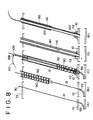
- Fig. 8 is a view for explaining a process until a mounting pipe is disposed;
- Fig. 9 is a front view showing an embodiment of an excavating machine used in the present invention; and
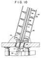
- Fig. 10 is an enlarged-scale view showing the excavating machine under the final process of excavation.
- Referring to Fig. 1, a rod propelling machine or
rod propeller 14 for rotating aflexible rod 12 like an oil-tempered wire about its axis while advancing the same is disposed in amain sewer pipe 10 embedded in the ground. Therod propeller 14 comprises asupport mechanism 15 for supporting respective mechanisms of the rod propeller. - The
support mechanism 15 is provided with abase member 16 extending along themain pipe 10 and a plurality ofjacks 18 disposed in spots longitudinally spaced apart from each other on thebase member 16 such as to maintain thebase member 16 to be in a fixed state relative to themain pipe 10. Thejacks 18 are disposed at positions angularly spaced apart from each other about the axis of themain pipe 10 and extend radially of themain pipe 10. On the tip of a rod of eachjack 18 is mounted apad 20 pressed against the inner surface of themain pipe 10 when the jack is expanded. - An
operating mechanism 21 for rotating therod 12 about its axis while advancing the same is supported by thebase member 16. As shown in Figs. 1 to 5, theoperating mechanism 21 is provided with a pair of rod-like guides 22 extending backwardly along therod 12 in themain pipe 10 from the rear end of thebase member 16 such that they are parallel with each other. The tip of eachguide 22 is secured to thebase member 16 by anut 24. To the rear end of eachguide 22 is secured by a nut 28 a connectingpiece 26 for interconnecting both theguides 22 to prevent their relative positional relationship from any change. - A
slider 30 of theoperating mechanism 21 is supported by theguides 22 to be slidable along theguides 22. Theslider 30 has through holes for receiving slidably theguides 22 and is connected to ajack 32 for moving back and forth theslider 30 along theguides 22. A cylinder of thejack 32 is secured to the connectingpiece 26 so as to extend backwardly from theslider 30. A rod of thejack 32 is secured to theslider 30 by anut 34. - As shown in Fig. 2, the
slider 30 is provided with a space which extends through theslider 30 along therod 12. In the space of theslider 30 is disposed achuck 36 of theoperating mechanism 21 such that the chuck is rotatable about the axis of therod 12 in the state of being clamped the rod. Achuck body 38 of thechuck 36 is rotatably supported by theslider 30 through a plurality ofbearings 40. - The
chuck body 38 is provided with a through hole for receiving slidably therod 12. The tip of the through hole is a hole having a small bore to such an extent that a slight gap is formed between thechuck body 38 and therod 12. On the contrary, a central portion of the through hole constitutes a space larger than the hole of the small bore. Also, the rear end of the through hole constitutes a conical space. In the conical space at the rear end of the through hole are disposed a plurality of clampingclaws 42 movable along therod 12. - The
respective claws 42 are subjected to force for protruding theclaws 42 from the central space, i.e., force for releasing therod 12 from theclamping claws 42, by acoiled spring 44 disposed in the central space. Also, acylinder mechanism 46 for advancing therespective claws 42 relative to thechuck body 38 is supported by thechuck body 38. - the
slider 30 supports amotor 48 for rotating thechuck body 38. As shown in Figs. 1 and 2, rotation of themotor 48 is transmitted to thechuck body 38 through a gear-like timing pulley 50 mounted on the rotary shaft of themotor 48, atiming belt 52 trained over thetiming pulley 50 and atiming pulley 54 provided on thechuck body 38 to mesh with thetiming belt 52. - As shown in Fig. 3, the
rod 12 extends rotatably slidably through thecylinder mechanism 46. Thus, thecylinder mechanism 46 is provided with a plurality ofbearings 56 for receiving rotatably slidably therod 12. Thechuck body 38 is also provided with abearing 58 for receiving therod 12 rotatably slidably. - The
base member 16 supports aguide mechanism 59 for guiding along the curved path therod 12, which is rotated by theoperating mechanism 21 while being drawn out along the axis of themain pipe 10. - As shown in Figs. 6 and 7, the
guide mechanism 59 is provided with a plurality ofbearings 60 which are respectively fitted in holes bored in the central portions ofsquare plates 62. Also, therespective bearings 60 are sequentially disposed betweenspacers 64 such that the rotary centers of the bearings are disposed along a curve having a predetermined radius of curvature. Eachplate 62 andspacer 64 are interconnected fixedly to each other by a plurality ofbolts 66 extending along the curved paths. In theadjacent bearings 60 are respectively fittedrings 68, through which therod 12 extends rotatably slidably. - At the time of propelling the rod, the
rod 12 is passed from theoperating mechanism 21 to theguide mechanism 59 and adrill 70 is mounted on the tip of therod 12. - Then, the
rod propeller 14 is disposed in a predetermined spot in themain pipe 10 by pushing therod propeller 14 by a predetermined distance from one vertical shaft or manhole communicating to themain pipe 10 to the other, or by inserting a wire extending from one manhole to the other into themain pipe 10, connecting therod propeller 14 to one end of the wire and then drawing the wire toward the other end thereof by a predetermined length. - Next, the
rod propeller 14 is secured to themain pipe 10 by expanding thejacks 18 of thesupport mechanism 15. Subsequently, themotor 48 is rotated, and thejack 32 is repetitively expanded and contracted in synchronism with the operation of thecylinder mechanism 46. That is, thecylinder mechanism 46 is expanded while thejack 32 is expanded, and thecylinder mechanism 46 is contracted while thejack 32 is contracted. - Accordingly, the
slider 30 reciprocates back and forth. Also, thechuck 36 reciprocates back and forth along with reciprocation of theslider 30. Further, thechuck 36 clamps therod 12 at the time of advancing and releases therod 12 at the time of retreating. - As a result, the
rod 12 repeats intermittently the process of rotating about its axis while advancing. By so doing, therod 12 penetrates the wall member of themain pipe 10 to be propelled toward the ground surface. As shown in Fig. 8(A), the tip of therod 12 finally projects upward from theground surface 72. Therod 12 can be advanced straight through its rotation with high speed. - As shown in Fig. 9, an excavating
machine 74 is installed on the ground, which utilizes therod 12 extending from themain pipe 10 for a guide while excavating a hole from the tip side of therod 12 toward themain pipe 10. - The excavating
machine 74 comprises achuck 78 fixed to the upper portion of asupport bed 76 to releasably clamp the tip of therod 12 protruded on the ground. Thesupport bed 76 supports aslider 80 to be movable parallelly to therod 12. Theslider 80 is moved by acylinder mechanism 82 mounted on thesupport bed 76. - An
excavating mechanism 84 for drilling a hole along therod 12 is removably mounted on theslider 80 byfittings excavating mechanism 84 in the embodiment shown in the drawing is an earth auger provided with atubular casing 90, ascrew conveyer 92 received rotatably in the casing and acutter 94 mounted on the tip of the screw conveyer. However, a different type of excavating mechanism may be applied to the present invention. - As clearly shown in Fig. 10, a
shaft 96 of thescrew conveyer 92 has a throughhole 98 extending through theshaft 96 along the axis thereof such as to receive rotatably movably therod 12. Also, the lower end of the throughhole 98 constitutes a small hole, through which therod 12 passes, and communicates to the outside through a plurality ofholes 100 extending radially of theshaft 96. - The
casing 90 andshaft 96 are supported rotatably about the axis of therod 12 byfittings motor 102 supported by thesupport bed 76 is transmitted through achain 104 to theshaft 96. - In excavation, after the tip of the
rod 12 is first inserted into thehole 98 of the excavatingmachine 84, the tip of therod 12 is clamped by thechuck 78 so as to tension therod 12. At this time, thechuck 36 of therod propeller 14 is operated to clamp therod 12. - In this state, the
motor 102 is operated and thecylinder mechanism 82 is expanded. Accordingly, when thescrew conveyer 92 is rotated about the axis of therod 12 while being advanced, thecasing 90 is advanced together with thescrew conveyer 92. As shown in Fig. 8(B), theexcavating mechanism 84 is then advanced along therod 12 and finally the tip of theexcavating mechanism 84 reaches themain pipe 10 as shown in Figs. 8(C) and Fig. 10. Consequently, a portion of a wall of themain pipe 10 is cut off by thecutter 94. - The hole excavated as above mentioned reaches accurately to the
main pipe 10 since theexcavating mechanism 84 is advanced by the guidance of therod 12. Therefore, the accurate hole can be easily excavated. - In laying the mounting pipe, a
cap 106 is first mounted on the upper end of theshaft 96 to close thehole 98 of theshaft 96 at the upper end of theshaft 96. As shown in Fig. 9, thecap 106 may be mounted before the excavation. Thecap 106 has anipple 108 communicating to thehole 98 in theshaft 96. - Next, as shown in Fig. 8(C), a
hose 110 is connected to thenipple 108 andseal agent 112 is poured from thehose 110. As shown in Fig. 10, theseal agent 112 flows out of thehole 98 through theholes 100 to close a gap between thecasing 90 and themain pipe 10. - Then, after the
screw conveyer 92 is removed together withcut pieces 114 of themain pipe 10, as shown in Fig. 8(D), the lateral sewer or mounting pipe 116 is inserted into thecasing 90 until the tip of the mounting pipe 116 is fitted in ahole 118 bored in themain pipe 10. The mounting pipe 116 may be inserted either manually or mechanically. - Thereafter, the chuck of the excavating
machine 74 releases therod 12. Then, therod 12 is drawn back by therod propeller 14, and therod propeller 14 is removed. Therod 12 can be drawn back by theoperating mechanism 21 of the rod propeller f14. Namely, therod 12 can be drawn back by repeating the process of drawing back theclaws 42 while clamping therod 12, and advancing theclaws 32 while releasing therod 12. - Next, as shown in Fig. 8(E),
seal agent 120 is poured from athin pipe 122 into the outer periphery of a bottom of the mounting pipe 116, and then thecasing 90 is removed. After the removal of thecasing 90, earth and sand are poured into a gap between thecasing 90 and the mounting pipe 116. Thus, the mounting pipe 116 is stabilized. - Further, the present invention can be applied not only to the method and apparatus for excavating holes used laying the mounting pipe 116, but also to a method and apparatus for excavating holes used for laying a pipe extending from a shaft to another shaft for example and other purpose holes.
Claims (13)
a step of rotating a rod (12) about its axis in a space provided in the ground while advancing the rod in the direction of penetrating a wall member (10) defining said space; and
a step of utilizing said advanced rod for a guide while excavating a hole in the ground (72) from the tip side of the rod toward said space.
a rod propelling machine (14) disposed in a space provided in the ground (72) and for rotating a rod (12) about its axis while advancing said rod; and
an excavating machine (74) utilizing said advanced rod for a guide while excavating a hole in the ground from the tip side of the rod toward said space;
wherein said rod propelling machine (14) includes operating means (21) for rotating said rod about its axis while advancing said rod and rod guiding means (59) provided in front of said operating means and for guiding said rod in the direction of penetrating a wall member (10) defining said space.
operating means (21) for clamping said rod and rotating said rod about its axis while advancing said rod;
means (59) for guiding said rod along a curved path; and
means (15) for supporting said operating means and guide means.
means (78) for clamping the tip of said rod;
excavating means (84) disposed coaxially with said rod to extend along said rod;
drive means (82,102,104) for rotating said excavating means about said rod while advancing said excavating means along said rod; and
means (76) for supporting said clamping means, excavating means and drive means.
Priority Applications (1)
| Application Number | Priority Date | Filing Date | Title |
|---|---|---|---|
| AT88113024T ATE58936T1 (en) | 1987-10-20 | 1988-08-10 | METHOD AND DEVICE FOR MAKING BORED HOLES IN THE SOIL. |
Applications Claiming Priority (2)
| Application Number | Priority Date | Filing Date | Title |
|---|---|---|---|
| JP262815/87 | 1987-10-20 | ||
| JP62262815A JPH01105897A (en) | 1987-10-20 | 1987-10-20 | Method and device for excavating hole |
Publications (2)
| Publication Number | Publication Date |
|---|---|
| EP0312724A1 true EP0312724A1 (en) | 1989-04-26 |
| EP0312724B1 EP0312724B1 (en) | 1990-12-05 |
Family
ID=17380996
Family Applications (1)
| Application Number | Title | Priority Date | Filing Date |
|---|---|---|---|
| EP88113024A Expired - Lifetime EP0312724B1 (en) | 1987-10-20 | 1988-08-10 | Method for excavating hole and apparatus therefor |
Country Status (11)
| Country | Link |
|---|---|
| US (1) | US4869619A (en) |
| EP (1) | EP0312724B1 (en) |
| JP (1) | JPH01105897A (en) |
| KR (1) | KR890006935A (en) |
| AT (1) | ATE58936T1 (en) |
| AU (1) | AU596311B2 (en) |
| CA (1) | CA1327788C (en) |
| DE (1) | DE3861236D1 (en) |
| DK (1) | DK168095B1 (en) |
| ES (1) | ES2019982B3 (en) |
| NO (1) | NO169608C (en) |
Cited By (1)
| Publication number | Priority date | Publication date | Assignee | Title |
|---|---|---|---|---|
| WO2007103417A3 (en) * | 2006-03-09 | 2007-12-21 | William E Shook | Connection between a lateral and main pipe and method for making same remotely |
Families Citing this family (11)
| Publication number | Priority date | Publication date | Assignee | Title |
|---|---|---|---|---|
| US5076730A (en) * | 1991-04-23 | 1991-12-31 | Bergey Michael J | Earth duct tunnel enlargement apparatus and method |
| US5364207A (en) * | 1993-03-26 | 1994-11-15 | Reber Cleve C | Method for making service connections to polyethylene pipe |
| US5649786A (en) * | 1993-03-26 | 1997-07-22 | Tti Trenchless Technologies, Inc. | Apparatus for down hole fusing |
| US5613807A (en) * | 1993-03-26 | 1997-03-25 | Tti Trenchless Technologies, Inc. | Apparatus for down hold fusing |
| CN1058933C (en) * | 1994-11-14 | 2000-11-29 | Tt1管线施工技术有限公司 | Apparatus and method for down hole fusing |
| US20030081998A1 (en) * | 2001-10-18 | 2003-05-01 | Yodock Leo J. | Barrier device with foam interior |
| CN100343566C (en) * | 2005-10-08 | 2007-10-17 | 上海隧道工程股份有限公司 | Reaming type mud and water balance micro-push bench |
| US7416364B2 (en) * | 2006-03-03 | 2008-08-26 | Yodock Iii Leo J | Pivot unit for barrier devices |
| US7537411B2 (en) * | 2007-05-18 | 2009-05-26 | Yodock Jr Leo J | End connector for barrier devices |
| JP6235372B2 (en) * | 2014-02-25 | 2017-11-22 | 鹿島建設株式会社 | Drilling device and drilling method |
| CN107476368B (en) * | 2017-08-25 | 2019-11-08 | 东阳市君泰建筑工程有限公司 | Riverway waste cleaning push plate |
Citations (7)
| Publication number | Priority date | Publication date | Assignee | Title |
|---|---|---|---|---|
| US2198016A (en) * | 1938-08-18 | 1940-04-23 | James C Rogers | Lateral drill mechanism |
| US2746719A (en) * | 1952-05-22 | 1956-05-22 | Alain R Seligman | Drilling device for large bores |
| US2837324A (en) * | 1955-04-04 | 1958-06-03 | West Canadian Collieries Ltd | Apparatus for drilling large holes between galleries |
| US3443649A (en) * | 1967-02-23 | 1969-05-13 | Stanley G Atkins | Apparatus for earth coring |
| US3486572A (en) * | 1967-02-28 | 1969-12-30 | Lawrence Mfg Co | Apparatus for forming inclined bores |
| US4176985A (en) * | 1975-07-14 | 1979-12-04 | Reading And Bates Construction Co. | System and method for installing production casings |
| GB2194183A (en) * | 1986-08-22 | 1988-03-02 | Perard Torque Tension Ltd | Drilling apparatus |
Family Cites Families (10)
| Publication number | Priority date | Publication date | Assignee | Title |
|---|---|---|---|---|
| DE1257077B (en) * | 1962-09-27 | 1967-12-28 | Wolfgang Ebeling Dipl Ing | Self-advancing pre-drilling machine |
| US4043136A (en) * | 1975-07-14 | 1977-08-23 | Tidril Corporation | System and method for installing production casings |
| JPS55132899A (en) * | 1979-04-05 | 1980-10-16 | Nippon Steel Corp | Method of inserting largeediameter pipe into curved smallldiameter hole |
| JPS5615276U (en) * | 1979-07-12 | 1981-02-09 | ||
| JPS5753512A (en) * | 1980-09-18 | 1982-03-30 | Toyo Ink Mfg Co Ltd | Water-based resin composition |
| JPS5758792A (en) * | 1980-09-24 | 1982-04-08 | Kumagai Gumi Co Ltd | Method of and apparatus for horizontal excavation from vertical hole |
| US4619555A (en) * | 1984-08-27 | 1986-10-28 | Press-Seal Gasket Corporation | Slipline adjustable manhole seal |
| US4784230A (en) * | 1985-05-14 | 1988-11-15 | Cherrington Martin D | Apparatus and method for installing a conduit within an arcuate bore |
| US4699224A (en) * | 1986-05-12 | 1987-10-13 | Sidewinder Joint Venture | Method and apparatus for lateral drilling in oil and gas wells |
| US4762186A (en) * | 1986-11-05 | 1988-08-09 | Atlantic Richfield Company | Medium curvature directional drilling method |
-
1987
- 1987-10-20 JP JP62262815A patent/JPH01105897A/en active Granted
-
1988
- 1988-06-14 CA CA000569475A patent/CA1327788C/en not_active Expired - Fee Related
- 1988-06-15 AU AU17745/88A patent/AU596311B2/en not_active Ceased
- 1988-06-22 KR KR1019880007530A patent/KR890006935A/en not_active Application Discontinuation
- 1988-07-28 US US07/225,181 patent/US4869619A/en not_active Expired - Fee Related
- 1988-08-10 DE DE8888113024T patent/DE3861236D1/en not_active Expired - Fee Related
- 1988-08-10 EP EP88113024A patent/EP0312724B1/en not_active Expired - Lifetime
- 1988-08-10 AT AT88113024T patent/ATE58936T1/en not_active IP Right Cessation
- 1988-08-10 ES ES88113024T patent/ES2019982B3/en not_active Expired - Lifetime
- 1988-10-19 NO NO884651A patent/NO169608C/en unknown
- 1988-10-19 DK DK581088A patent/DK168095B1/en not_active IP Right Cessation
Patent Citations (7)
| Publication number | Priority date | Publication date | Assignee | Title |
|---|---|---|---|---|
| US2198016A (en) * | 1938-08-18 | 1940-04-23 | James C Rogers | Lateral drill mechanism |
| US2746719A (en) * | 1952-05-22 | 1956-05-22 | Alain R Seligman | Drilling device for large bores |
| US2837324A (en) * | 1955-04-04 | 1958-06-03 | West Canadian Collieries Ltd | Apparatus for drilling large holes between galleries |
| US3443649A (en) * | 1967-02-23 | 1969-05-13 | Stanley G Atkins | Apparatus for earth coring |
| US3486572A (en) * | 1967-02-28 | 1969-12-30 | Lawrence Mfg Co | Apparatus for forming inclined bores |
| US4176985A (en) * | 1975-07-14 | 1979-12-04 | Reading And Bates Construction Co. | System and method for installing production casings |
| GB2194183A (en) * | 1986-08-22 | 1988-03-02 | Perard Torque Tension Ltd | Drilling apparatus |
Cited By (2)
| Publication number | Priority date | Publication date | Assignee | Title |
|---|---|---|---|---|
| WO2007103417A3 (en) * | 2006-03-09 | 2007-12-21 | William E Shook | Connection between a lateral and main pipe and method for making same remotely |
| US7674072B2 (en) | 2006-03-09 | 2010-03-09 | Shook William E | Connection between a lateral and main pipe and method for making same |
Also Published As
| Publication number | Publication date |
|---|---|
| AU1774588A (en) | 1989-04-20 |
| US4869619A (en) | 1989-09-26 |
| DK581088A (en) | 1989-04-21 |
| JPH01105897A (en) | 1989-04-24 |
| NO884651D0 (en) | 1988-10-19 |
| NO884651L (en) | 1989-04-21 |
| NO169608B (en) | 1992-04-06 |
| ES2019982B3 (en) | 1991-07-16 |
| NO169608C (en) | 1992-07-15 |
| ATE58936T1 (en) | 1990-12-15 |
| KR890006935A (en) | 1989-06-17 |
| DE3861236D1 (en) | 1991-01-17 |
| CA1327788C (en) | 1994-03-15 |
| EP0312724B1 (en) | 1990-12-05 |
| DK581088D0 (en) | 1988-10-19 |
| JPH0528315B2 (en) | 1993-04-23 |
| DK168095B1 (en) | 1994-02-07 |
| AU596311B2 (en) | 1990-04-26 |
Similar Documents
| Publication | Publication Date | Title |
|---|---|---|
| US4869619A (en) | Method for excavating hole and apparatus therefor | |
| US4648454A (en) | Robot | |
| US4553612A (en) | Earth boring machine | |
| US4953638A (en) | Method of and apparatus for drilling a horizontal controlled borehole in the earth | |
| EP0058517A2 (en) | Remote drilling apparatus | |
| US5125768A (en) | Method and apparatus for the production of underground pipelines | |
| FI92507B (en) | Method and apparatus for guiding pipes forced into the ground | |
| CA1320124C (en) | Boring device for lining material in branched portions of lined conduit | |
| EP0103283A2 (en) | An apparatus for inserting a tool into the ground and continuously rotating it | |
| JP2505870B2 (en) | How to drill a lining pipe | |
| JPS63232905A (en) | Drilling device | |
| US5984583A (en) | Methods and apparatus for directionally drilling a bore and placing pipe | |
| JP3436695B2 (en) | Drilling method and core boring machine | |
| JPH09234699A (en) | Drilling guide device for drilling machine of large diameter tube | |
| JP2688134B2 (en) | Pipe joining device | |
| JP6195376B2 (en) | Ruler for placing steel pipe sheet pile, method for placing steel pipe sheet pile, and swivel excavator used for the method for placing steel pipe sheet pile | |
| KR102509897B1 (en) | Moving type perforator with three perforating rods for free surface formation and the method of forming free surface on rock using the same | |
| JP2001329554A (en) | Hole drilling method for concrete structure and concrete core cutter | |
| JP2022143914A (en) | Manhole barrel frame removing device and barrel frame removing method | |
| JP2672635B2 (en) | Direction control device for punching machine | |
| JP2022115154A (en) | Cutting device, cutting method, and earthquake resistant structure | |
| JPH0448158B2 (en) | ||
| JPH0257198B2 (en) | ||
| JPH0643699B2 (en) | Equipment for cutting underground objects | |
| JPH089864B2 (en) | Pile press-fitting method on hard ground |
Legal Events
| Date | Code | Title | Description |
|---|---|---|---|
| PUAI | Public reference made under article 153(3) epc to a published international application that has entered the european phase |
Free format text: ORIGINAL CODE: 0009012 |
|
| AK | Designated contracting states |
Kind code of ref document: A1 Designated state(s): AT BE CH DE ES FR GB IT LI LU NL SE |
|
| 17P | Request for examination filed |
Effective date: 19890801 |
|
| 17Q | First examination report despatched |
Effective date: 19891006 |
|
| GRAA | (expected) grant |
Free format text: ORIGINAL CODE: 0009210 |
|
| AK | Designated contracting states |
Kind code of ref document: B1 Designated state(s): AT BE CH DE ES FR GB IT LI LU NL SE |
|
| REF | Corresponds to: |
Ref document number: 58936 Country of ref document: AT Date of ref document: 19901215 Kind code of ref document: T |
|
| ET | Fr: translation filed | ||
| REF | Corresponds to: |
Ref document number: 3861236 Country of ref document: DE Date of ref document: 19910117 |
|
| ITF | It: translation for a ep patent filed |
Owner name: GUZZI E RAVIZZA S.R.L. |
|
| PLBE | No opposition filed within time limit |
Free format text: ORIGINAL CODE: 0009261 |
|
| STAA | Information on the status of an ep patent application or granted ep patent |
Free format text: STATUS: NO OPPOSITION FILED WITHIN TIME LIMIT |
|
| 26N | No opposition filed | ||
| ITTA | It: last paid annual fee | ||
| EPTA | Lu: last paid annual fee | ||
| PGFP | Annual fee paid to national office [announced via postgrant information from national office to epo] |
Ref country code: GB Payment date: 19940720 Year of fee payment: 7 |
|
| PGFP | Annual fee paid to national office [announced via postgrant information from national office to epo] |
Ref country code: LU Payment date: 19940801 Year of fee payment: 7 |
|
| PGFP | Annual fee paid to national office [announced via postgrant information from national office to epo] |
Ref country code: FR Payment date: 19940817 Year of fee payment: 7 |
|
| PGFP | Annual fee paid to national office [announced via postgrant information from national office to epo] |
Ref country code: AT Payment date: 19940823 Year of fee payment: 7 |
|
| PGFP | Annual fee paid to national office [announced via postgrant information from national office to epo] |
Ref country code: SE Payment date: 19940824 Year of fee payment: 7 |
|
| PGFP | Annual fee paid to national office [announced via postgrant information from national office to epo] |
Ref country code: ES Payment date: 19940830 Year of fee payment: 7 |
|
| PGFP | Annual fee paid to national office [announced via postgrant information from national office to epo] |
Ref country code: NL Payment date: 19940831 Year of fee payment: 7 |
|
| PGFP | Annual fee paid to national office [announced via postgrant information from national office to epo] |
Ref country code: BE Payment date: 19940902 Year of fee payment: 7 |
|
| PGFP | Annual fee paid to national office [announced via postgrant information from national office to epo] |
Ref country code: CH Payment date: 19940921 Year of fee payment: 7 |
|
| PGFP | Annual fee paid to national office [announced via postgrant information from national office to epo] |
Ref country code: DE Payment date: 19941018 Year of fee payment: 7 |
|
| EAL | Se: european patent in force in sweden |
Ref document number: 88113024.9 |
|
| PG25 | Lapsed in a contracting state [announced via postgrant information from national office to epo] |
Ref country code: LU Free format text: LAPSE BECAUSE OF NON-PAYMENT OF DUE FEES Effective date: 19950810 Ref country code: GB Effective date: 19950810 Ref country code: AT Effective date: 19950810 |
|
| PG25 | Lapsed in a contracting state [announced via postgrant information from national office to epo] |
Ref country code: SE Effective date: 19950811 Ref country code: ES Free format text: LAPSE BECAUSE OF EXPIRATION OF PROTECTION Effective date: 19950811 |
|
| PG25 | Lapsed in a contracting state [announced via postgrant information from national office to epo] |
Ref country code: LI Effective date: 19950831 Ref country code: CH Effective date: 19950831 Ref country code: BE Effective date: 19950831 |
|
| BERE | Be: lapsed |
Owner name: ISEKI KAIHATSU KOKI K.K. Effective date: 19950831 |
|
| PG25 | Lapsed in a contracting state [announced via postgrant information from national office to epo] |
Ref country code: NL Effective date: 19960301 |
|
| GBPC | Gb: european patent ceased through non-payment of renewal fee |
Effective date: 19950810 |
|
| REG | Reference to a national code |
Ref country code: CH Ref legal event code: PL |
|
| PG25 | Lapsed in a contracting state [announced via postgrant information from national office to epo] |
Ref country code: FR Effective date: 19960430 |
|
| NLV4 | Nl: lapsed or anulled due to non-payment of the annual fee |
Effective date: 19960301 |
|
| PG25 | Lapsed in a contracting state [announced via postgrant information from national office to epo] |
Ref country code: DE Effective date: 19960501 |
|
| EUG | Se: european patent has lapsed |
Ref document number: 88113024.9 |
|
| REG | Reference to a national code |
Ref country code: FR Ref legal event code: ST |
|
| REG | Reference to a national code |
Ref country code: ES Ref legal event code: FD2A Effective date: 19990601 |
|
| PG25 | Lapsed in a contracting state [announced via postgrant information from national office to epo] |
Ref country code: IT Free format text: LAPSE BECAUSE OF NON-PAYMENT OF DUE FEES;WARNING: LAPSES OF ITALIAN PATENTS WITH EFFECTIVE DATE BEFORE 2007 MAY HAVE OCCURRED AT ANY TIME BEFORE 2007. THE CORRECT EFFECTIVE DATE MAY BE DIFFERENT FROM THE ONE RECORDED. Effective date: 20050810 |