EP0309880A2 - Hand tool - Google Patents
Hand tool Download PDFInfo
- Publication number
- EP0309880A2 EP0309880A2 EP88115440A EP88115440A EP0309880A2 EP 0309880 A2 EP0309880 A2 EP 0309880A2 EP 88115440 A EP88115440 A EP 88115440A EP 88115440 A EP88115440 A EP 88115440A EP 0309880 A2 EP0309880 A2 EP 0309880A2
- Authority
- EP
- European Patent Office
- Prior art keywords
- toothing
- handle
- slide
- tool head
- counter
- Prior art date
- Legal status (The legal status is an assumption and is not a legal conclusion. Google has not performed a legal analysis and makes no representation as to the accuracy of the status listed.)
- Granted
Links
Images

Classifications
-
- B—PERFORMING OPERATIONS; TRANSPORTING
- B25—HAND TOOLS; PORTABLE POWER-DRIVEN TOOLS; MANIPULATORS
- B25G—HANDLES FOR HAND IMPLEMENTS
- B25G1/00—Handle constructions
- B25G1/06—Handle constructions reversible or adjustable for position
- B25G1/063—Handle constructions reversible or adjustable for position for screwdrivers, wrenches or spanners
-
- B—PERFORMING OPERATIONS; TRANSPORTING
- B25—HAND TOOLS; PORTABLE POWER-DRIVEN TOOLS; MANIPULATORS
- B25G—HANDLES FOR HAND IMPLEMENTS
- B25G3/00—Attaching handles to the implements
- B25G3/38—Hinged, pivoted, swivelling, or folding joints
Definitions
- the invention relates to a hand tool with a tool head, for example in the form of a square drive, a spanner or spanner, a switchable ratchet or the like, and with a handle on which the tool head is pivotally mounted about an axis extending transversely to the longitudinal axis of the handle and in one of Several angular positions can be positively determined, for which purpose the tool head is provided at its handle-side end surrounding the pivot axis with a toothing which is formed on a surface which is concentric to the pivot axis and forms part of a circular cylinder and into which the respective angular position of the tool head is opposite Handle engaging locking piece engages positively, which is designed as a slide and is provided with a mating toothing engaging in the toothing of the tool head.
- Hand tools of this type are known in particular as reversible ratchets, but also as articulated handles, in which the tool head carrying the actual tool, for example a socket wrench, is pivotably mounted on the handle, so that the respective tool can be used in the respectively required angular position with respect to the longitudinal axis of the handle.
- the tool head carrying the actual tool for example a socket wrench
- the handle pivotably mounted on the handle, so that the respective tool can be used in the respectively required angular position with respect to the longitudinal axis of the handle.
- a hand tool of the type described is known, in which the slide is guided displaceably in the longitudinal direction of the handle.
- the slide is provided with a tooth engaging in the toothing of the tool head and is displaced by a cam, which is rotatably mounted in the handle and in one position presses the tooth of the slide into a tooth gap of the toothing on the tool head, while in the 180 ° twisted position of the tooth is withdrawn from the tooth gap due to the action of a spring, so that the tool head can be pivoted.
- This known construction has a complex and prone to failure structure.
- the invention is based on the object of developing a hand tool of the type presupposed as known in such a way that, with a structurally simple structure, the tool head is fixed reliably and also transmits high forces.
- the solution to this problem by the invention is characterized in that the slide along an oblique to the pivot axis sliding axis between two ends positions is displaceable, in which one engages the counter-toothing in the toothing and in the other the counter-toothing is due to the inclined position of the sliding axis at a distance from the toothing, which excludes an engagement of the two toothings.
- the tool head is positively attached to the handle in each of the selected positions by means of the slider, since the slider, which is displaceable on the oblique sliding axis, engages with its toothing over a large area in the toothing of the tool head in one end position and is in turn positively mounted on the handle. High forces can thus also be transmitted without the risk that the tooth engagement is canceled. If, on the other hand, the slide is moved into the other end position, in which its toothing is withdrawn from the counter toothing of the tool head due to the inclined position of the sliding axis, the tool head can be pivoted in a simple manner.
- the form-fitting fixing of the tool head on the handle is thus canceled after a lateral displacement of the locking piece designed as a slide, so that the tool head can then be moved by hand into the desired angular position relative to the handle, in which it can be moved by pushing back the slide-like Blocking piece is secured again by shape intervention.
- the sliding axis can be formed by a bearing pin arranged obliquely to the pivot axis in the handle, on which the slide is slidably mounted.
- the bearing pin can be arranged in the bifurcated end of the handle and the part of the slide provided with the counter-serration can be approximately half as wide as the serration on the tool head which is also in the bifurcation, so that in one End position in which the slide rests on the left part of the fork, for example, there is a tooth mesh between the teeth and counter-toothing, and in the other end position in which the slide rests on the right part of the fork, the tooth engagement is canceled and the tool head is pivoted relative to the handle can.
- this latching element can be designed as a spring-loaded ball, which is arranged in a bore in the handle and engages on the side of the slide opposite the counter-toothing.
- this hand tool comprises a tool head 1 and a handle 2.
- the tool head 1 is designed as a reversible ratchet
- the tool head 1 of the first exemplary embodiment according to FIGS. 1 to 6 is designed as a square drive
- the second embodiment according to FIGS. 7 and 8 as a ring spanner.
- the tool head 1 is pivotally mounted on the handle 2 about a pivot axis A, which extends transversely to the longitudinal axis of the handle.
- this pivot axis A is formed in each case by a screw bolt 3 which is screwed into a fork-shaped end of the handle 2 and here engages in the handle-side end of the tool head 1 which projects into the forked opening of the handle 2.
- the tool head 1 is provided on its handle-side end surrounding the pivot axis A with a toothing 4 which is formed on a surface which is aligned concentrically with the pivot axis A and forms part of a circular cylinder, as shown in particular in FIGS. 2, 4, 6, 8 and 10 emerges.
- a locking piece engages in this toothing 4 in a form-fitting manner and, by its engagement, fixes the tool head 1 in the respective angular position relative to the handle 2.
- the locking piece is designed as a slide 6, which is provided with counter-toothing 6a, which corresponds to the toothing 4 of the tool head 1.
- the slide 6 is displaceable along a sliding axis S which lies in the same longitudinal center plane of the handle 2 as the pivot axis A, but extends obliquely with respect to the pivot axis A.
- this sliding axis S is formed by a bearing pin 7 which extends between the two arms of the fork-shaped end of the handle 2, as can best be seen in FIGS. 3 and 5.
- the slide 6 provided with the counter-toothing 6a can be displaced between two end positions, which are shown in FIG. 3 or in FIG.
- the counter toothing 6a of the slide 6 engages in the end position shown in FIG. 3 in the toothing 4 of the tool head 1 and thus secures the tool head 1 against pivoting about the pivot axis A
- the counter toothing 6a of the slide 6 is in the other end position according to FIG. 5 out of engagement with the toothing 4, so that in this case the tool head 1 can be pivoted about the pivot axis A by hand.
- the inclined position of the bearing pin 7 is chosen such that the slide between the left end position in FIG. 3 and the right end position in FIG. 5 is removed by at least the amount relative to the toothing 4 that corresponds to the depth of the toothing 4 and 6a.
- FIGS. 1 and 2 and 7 to 11 show furthermore, that the slider 6 is provided with gripping surfaces 6b both on the front and on the back, which facilitate displacement of the slider 6.
- Figures 2, 8 and 10 show that the slide 6 is secured in the locked position by a non-positively engaging locking member, which in the exemplary embodiments is designed as a ball 8 loaded by a spring 8a, which is arranged in a bore in the handle 2 are. The ball 8 engages on the side of the slide 6 opposite the counter-toothing 6a.
- the locking piece designed as a slider 6 can be actuated by the fingers of the hand that holds the tool, so that here, too, a one-handed release of the locking device, pivoting of the tool head 1 relative to the handle and subsequent attachment of the locking device is possible .
- a swivel axis S sliding axis 1 tool head 2 handles 3 bolts 4 teeth 6 sliders 6a counter toothing 6b grip surface 7 bearing pin 8 bullet 8a spring
Abstract
Description
Die Erfindung betrifft ein Handwerkzeug mit einem Werkzeugkopf, beispielsweise in Form eines Antriebsvierkants, eines Ring- oder Maulschlüssels, einer umschaltbaren Knarre oder dgl., sowie mit einem Griff, an dem der Werkzeugkopf um eine quer zur Grifflängsachse verlaufende Achse verschwenkbar gelagert und in einer von mehreren Winkelstellungen formschlüssig feststellbar ist, wozu der Werkzeugkopf an seinem die Schwenkachse umgebenden, griffseitigen Ende mit einer Verzahnung versehen ist, die auf einer konzentrisch zur Schwenkachse ausgerichteten, einen Teil eines Kreiszylinders bildenden Fläche ausgebildet ist und in die ein die jeweilige Winkelstellung des Werkzeugkopfes gegenüber dem Griff festlegendes Sperrstück formschlüssig eingreift, das als Schieber ausgebildet und mit einer in die Verzahnung des Werkzeugkopfes eingreifenden Gegenverzahnung versehen ist.The invention relates to a hand tool with a tool head, for example in the form of a square drive, a spanner or spanner, a switchable ratchet or the like, and with a handle on which the tool head is pivotally mounted about an axis extending transversely to the longitudinal axis of the handle and in one of Several angular positions can be positively determined, for which purpose the tool head is provided at its handle-side end surrounding the pivot axis with a toothing which is formed on a surface which is concentric to the pivot axis and forms part of a circular cylinder and into which the respective angular position of the tool head is opposite Handle engaging locking piece engages positively, which is designed as a slide and is provided with a mating toothing engaging in the toothing of the tool head.
Derartige Handwerkzeuge sind insbesondere als Umschaltknarren, aber auch als Gelenkgriffe bekannt, bei denen der das eigentliche Werkzeug, beispielsweise einen Steckschlüssel tragende Werkzeugkopf verschwenkbar am Griff gelagert ist, so daß das jeweilige Werkzeug in der jeweils erforderlichen Winkelstellung gegenüber der Grifflängsachse eingesetzt werden kann. Hierbei gibt es verschiedene bekannte Konstruktionen, um den Werkzeugkopf in einer von mehreren Winkelstellungen gegenüber dem Griff formschlüssig festzulegen.Hand tools of this type are known in particular as reversible ratchets, but also as articulated handles, in which the tool head carrying the actual tool, for example a socket wrench, is pivotably mounted on the handle, so that the respective tool can be used in the respectively required angular position with respect to the longitudinal axis of the handle. There are various known designs for positively locking the tool head in one of several angular positions relative to the handle.
Aus der DE-OS 30 06 651 ist ein Handwerkzeug der eingangs beschriebenen Art bekannt, bei dem der Schieber in Längsrichtung des Griffes verschiebbar geführt ist. Der Schieber ist mit einem in die Verzahnung des Werkzeugkopfes eingreifenden Zahn versehen und wird durch eine Nocke verschoben, die drehbar im Griff gelagert ist und in der einen Stellung den Zahn des Schiebers in eine Zahnlücke der Verzahnung am Werkzeugkopf eindrückt, wogegen in der um 180° verdrehten Stellung der Zahn aufgrund der Wirkung einer Feder aus der Zahnlücke zurückgezogen ist, so daß der Werkzeugkopf verschwenkt werden kann. Diese bekannte Konstruktion hat einen aufwendigen und störanfälligen Aufbau.From DE-OS 30 06 651 a hand tool of the type described is known, in which the slide is guided displaceably in the longitudinal direction of the handle. The slide is provided with a tooth engaging in the toothing of the tool head and is displaced by a cam, which is rotatably mounted in the handle and in one position presses the tooth of the slide into a tooth gap of the toothing on the tool head, while in the 180 ° twisted position of the tooth is withdrawn from the tooth gap due to the action of a spring, so that the tool head can be pivoted. This known construction has a complex and prone to failure structure.
Auch aus der US-PS 1,942,640 ist ein Handwerkzeug der eingangs beschriebenen Art bekannt, bei dem der Schieber im wesentlichen in Längsrichtung des Griffes verschiebbar ist. Bei dieser bekannten Konstruktion wird der Schieber von Hand entgegen der Kraft einer Feder zurückgezogen, um den Zahneingriff zwischen Schieber und Werkzeugkopf zu lösen; der erneute Zahneingriff wird hierbei im wesentlichen durch Federkraft hergestellt, so daß bei hohen Belastungen nicht ausgeschlossen werden kann, daß die Federkraft überwunden, der Schieber zurückgedrückt und die Arretierung des Werkzeugkopfes aufgehoben wird.Also known from US Pat. No. 1,942,640 is a hand tool of the type described in the introduction, in which the slide can be displaced essentially in the longitudinal direction of the handle. In this known construction, the slide is pulled back by hand against the force of a spring in order to release the tooth engagement between the slide and the tool head; the renewed tooth engagement is produced essentially by spring force, so that it cannot be ruled out at high loads that the spring force is overcome, the slide is pushed back and the locking of the tool head is released.
Der Erfindung liegt die Aufgabe zugrunde, ein Handwerkzeug der als bekannt vorausgesetzten Art derart weiterzubilden, daß bei konstruktiv einfachem Aufbau eine zuverlässige und auch hohe Kräfte übertragende Festlegung des Werkzeugkopfes erfolgt.The invention is based on the object of developing a hand tool of the type presupposed as known in such a way that, with a structurally simple structure, the tool head is fixed reliably and also transmits high forces.
Die Lösung dieser Aufgabenstellung durch die Erfindung ist dadurch gekennzeichnet, daß der Schieber längs einer schräg zur Schwenkachse verlaufenden Schiebeachse zwischen zwei End stellungen verschiebbar ist, in deren einer die Gegenverzahnung in die Verzahnung eingreift und in deren anderer die Gegenverzahnung aufgrund der Schrägstellung der Schiebeachse sich in einem Abstand von der Verzahnung befindet, der einen Eingriff der beiden Verzahnungen ausschließt.The solution to this problem by the invention is characterized in that the slide along an oblique to the pivot axis sliding axis between two ends positions is displaceable, in which one engages the counter-toothing in the toothing and in the other the counter-toothing is due to the inclined position of the sliding axis at a distance from the toothing, which excludes an engagement of the two toothings.
Bei dieser erfindungsgemäßen Ausbildung wird der Werkzeugkopf in jeder der gewählten Stellungen mittels des Schiebers formschlüssig am Griff festgelegt, da der auf der schrägen Schiebeachse verschiebbare Schieber in der einen Endstellung mit seiner Verzahnung großflächig in die Verzahnung des Werkzeugkopfes eingreift und seinerseits formschlüssig am Griff gelagert ist. Es können somit auch hohe Kräfte ohne die Gefahr übertragen werden, daß der Zahneingriff aufgehoben wird. Wird dagegen der Schieber in die andere Endstellung überführt, in der seine Verzahnung aufgrund der Schrägstellung der Schiebeachse aus der Gegenverzahnung des Werkzeugkopfes zurückgezogen ist, kann auf einfache Weise ein Verschwenken des Werkzeugkopfes erfolgen. Bei dieser Ausführung wird somit nach einem seitlichen Verschieben des als Schieber ausgebildeten Sperrstückes die formschlüssige Festlegung des Werkzeugkopfes am Griff aufgehoben, so daß der Werkzeugkopf anschließend von Hand in die jeweils gewünschte Winkelstellung gegenüber dem Griff gebracht werden kann, in der er durch ein Zurückschieben des schieberartigen Sperrstückes erneut durch Formeingriff gesichert wird.In this embodiment according to the invention, the tool head is positively attached to the handle in each of the selected positions by means of the slider, since the slider, which is displaceable on the oblique sliding axis, engages with its toothing over a large area in the toothing of the tool head in one end position and is in turn positively mounted on the handle. High forces can thus also be transmitted without the risk that the tooth engagement is canceled. If, on the other hand, the slide is moved into the other end position, in which its toothing is withdrawn from the counter toothing of the tool head due to the inclined position of the sliding axis, the tool head can be pivoted in a simple manner. In this embodiment, the form-fitting fixing of the tool head on the handle is thus canceled after a lateral displacement of the locking piece designed as a slide, so that the tool head can then be moved by hand into the desired angular position relative to the handle, in which it can be moved by pushing back the slide-like Blocking piece is secured again by shape intervention.
Bei einer bevorzugten Ausführungsform der Erfindung kann die Schiebeachse durch einen schräg zur Schwenkachse im Griff angeordneten Lagerstift gebildet werden, auf dem der Schieber verschiebbar gelagert ist. Gemäß einem weiteren Merkmal kann der Lagerstift im gegabelten Ende des Griffes angeordnet und der mit der Gegenverzahnung versehene Teil des Schiebers etwa halb so breit wie die ebenfalls in der Gabelung liegende Verzahnung am Werkzeugkopf ausgebildet sein, so daß in der einen Endstellung, in der der Schieber z.B. am linken Teil der Gabel anliegt, ein Zahneingriff zwischen Verzahnung und Gegenverzahnung vorliegt und in der anderen Endstellung, in der der Schieber am rechten Teil der Gabel anliegt, der Zahneingriff aufgehoben ist und der Werkzeugkopf gegenüber dem Griff verschwenkt werden kann.In a preferred embodiment of the invention, the sliding axis can be formed by a bearing pin arranged obliquely to the pivot axis in the handle, on which the slide is slidably mounted. According to a further feature, the bearing pin can be arranged in the bifurcated end of the handle and the part of the slide provided with the counter-serration can be approximately half as wide as the serration on the tool head which is also in the bifurcation, so that in one End position in which the slide rests on the left part of the fork, for example, there is a tooth mesh between the teeth and counter-toothing, and in the other end position in which the slide rests on the right part of the fork, the tooth engagement is canceled and the tool head is pivoted relative to the handle can.
Mit der Erfindung wird schließlich vorgeschlagen, den Schieber in der Sperrstellung durch ein kraftschlüssig an ihm angreifendes Rastglied zu sichern. Dieses Rastglied kann bei einer bevorzugten Ausführung als eine federbelastete Kugel ausgebildet sein, die in einer Bohrung des Griffes angeordnet ist und an der der Gegenverzahnung gegenüberliegenden Seite des Schiebers angreift.Finally, the invention proposes to secure the slide in the locked position by means of a non-positively engaging locking member. In a preferred embodiment, this latching element can be designed as a spring-loaded ball, which is arranged in a bore in the handle and engages on the side of the slide opposite the counter-toothing.
Auf der Zeichnung sind drei Ausführungsbeispiele des erfindungsgemäßen Handwerkzeuges dargestellt, und zwar zeigen:
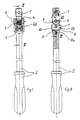
- Fig. 1 eine Draufsicht auf ein erstes Ausführungsbeispiel eines Handwerkzeugs,
- Fig. 2 das Handwerkzeug gemäß Fig.1 in einem Längsschnitt gemäß der Schnittlinie II - II in Fig.1,
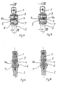
- Fig. 3 eine vergrößerte Darstellung eines Teilschnittes gemäß der Schnittlinie III - III in Fig.2 mit in der Sperrstellung befindlichem Sperrstück,
- Fig. 4 einen Schnitt gemäß der Schnittlinie IV - IV in Fig.3,
- Fig. 5 eine der Fig.3 entsprechende Darstellung mit in der Außereingriffstellung befindlichem Sperrstück,
- Fig. 6 einen Schnitt gemäß der Schnittlinie VI - VI in Fig.5,
- Fig. 7 eine Draufsicht auf eine zweite Ausführungsform eines Handwerkzeugs,
- Fig. 8 einen Längsschnitt durch das Werkzeug gemäß Fig.7 entsprechend der Schnittlinie VIII - VIII in Fig.7,
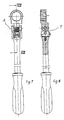
- Fig. 9 eine Draufsicht auf eine weitere, als Gelenkknarre ausgebildete Ausführungsform,
- Fig.10 einen Schnitt gemäß der Schnittlinie X - X in Fig.9 und
- Fig.11 eine Ansicht des Werkzeuges gemäß den Figuren 9 und 10 von unten.
- 1 is a plan view of a first embodiment of a hand tool,
- 2 shows the hand tool according to FIG. 1 in a longitudinal section along the section line II-II in FIG. 1,
- 3 is an enlarged view of a partial section along the section line III - III in Figure 2 with the locking piece in the locked position,
- 4 shows a section along the section line IV - IV in FIG. 3,
- 5 shows a representation corresponding to FIG. 3 with the locking piece in the disengaged position,
- 6 shows a section along the section line VI - VI in FIG. 5,
- 7 is a plan view of a second embodiment of a hand tool,
- 8 shows a longitudinal section through the tool according to FIG. 7 along the section line VIII - VIII in FIG. 7,
- 9 is a plan view of a further embodiment designed as an articulated ratchet,
- 10 shows a section along the section line X - X in Fig.9 and
- 11 shows a view of the tool according to FIGS. 9 and 10 from below.
Bei sämtlichen Ausführungsformen des auf den Zeichnungen dargestellten Handwerkzeuges umfaßt dieses Handwerkzeug einen Werkzeugkopf 1 und einen Griff 2. Der Werkzeugkopf 1 ist beim Ausführungsbeispiel gemäß den Figuren 9 bis 11 als umschaltbare Knarre ausgebildet, wogegen der Werkzeugkopf 1 des ersten Ausführungsbeispiels nach den Figuren 1 bis 6 als Antriebsvierkant und des zweiten Ausführungsbeispiels nach den Figuren 7 und 8 als Ringschlüssel ausgebildet ist.In all embodiments of the hand tool shown in the drawings, this hand tool comprises a
Bei allen Ausführungen ist der Werkzeugkopf 1 um eine Schwenkachse A, die quer zur Grifflängsachse verläuft, verschwenkbar am Griff 2 gelagert. Diese Schwenkachse A wird bei den dargestellten Ausführungen jeweils durch einen Schraubenbolzen 3 gebildet, der in ein gabelförmiges Ende des Griffes 2 eingeschraubt ist und hierbei in das griffseitige Ende des Werkzeugkopfes 1 eingreift, das in die gegabelte Öffnung des Griffes 2 hineinragt.In all versions, the
Der Werkzeugkopf 1 ist unabhängig von seiner Ausbildung an seinem die Schwenkachse A umgebenden, griffseitigen Ende mit einer Verzahnung 4 versehen, die auf einer konzentrisch zur Schwenkachse A ausgerichteten, einen Teil eines Kreiszylinders bildenden Fläche ausgebildet ist, wie insbesondere aus den Figuren 2, 4, 6, 8 und 10 hervorgeht. In diese Verzahnung 4 greift formschlüssig ein Sperrstück ein, das durch seinen Eingriff den Werkzeugkopf 1 in der jeweiligen Winkelstellung gegenüber dem Griff 2 festlegt.Regardless of its design, the
Das Sperrstück ist als Schieber 6 ausgebildet, der mit einer Gegenverzahnung 6a versehen ist, die mit der Verzahnung 4 des Werkzeugkopfes 1 korrespondiert. Außerdem ist der Schieber 6 längs einer Schiebeachse S verschiebbar, die in derselben Längsmittelebene des Griffes 2 wie die Schwenkachse A liegt, jedoch schräg gegenüber der Schwenkachse A verläuft. Bei den dargestellten Ausführungsbeispielen wird diese Schiebeachse S durch einen Lagerstift 7 gebildet, der sich zwischen den beiden Armen des gabelförmigen Endes des Griffes 2 erstreckt, wie am besten in den Figuren 3 und 5 zu erkennen ist. Auf diesem Lagerstift 7 ist der mit der Gegenverzahnung 6a versehene Schieber 6 zwischen zwei Endstellungen verschiebbar, die in Fig.3 bzw. in Fig.5 eingezeichnet sind. Während die Gegenverzahnung 6a des Schiebers 6 in der in Fig.3 dargestellten Endstellung in die Verzahnung 4 des Werkzeugkopfes 1 eingreift und damit den Werkzeugkopf 1 gegen Verschwenken um die Schwenkachse A sichert, steht die Gegenverzahnung 6a des Schiebers 6 in der anderen Endstellung gemäß Fig.5 außer Eingriff mit der Verzahnung 4, so daß in diesem Fall der Werkzeugkopf 1 um die Schwenkachse A von Hand verschwenkt werden kann. Die Schrägstellung des Lagerstiftes 7 ist hierbei derart gewählt, daß der Schieber zwischen der linken Endstellung in Fig.3 und der rechten Endstellung in Fig.5 mindestens um den Betrag gegenüber der Verzahnung 4 entfernt wird, der der Tiefe der Verzahnungen 4 und 6a entspricht.The locking piece is designed as a
Wie insbesondere aus den Figuren 3 bis 6 hervorgeht, ist der mit der Gegenverzahnung 6a versehene Teil des Schiebers 6 etwa halb so breit wie die in der Gabelung des Griffes 2 liegende Verzahnung 4 des Werkzeugkopfes 1. Die Figuren 1 und 2 sowie 7 bis 11 zeigen weiterhin, daß der Schieber 6 sowohl auf der Vorderseite als auch auf der Rückseite mit Griffflächen 6b versehen ist, die ein Verschieben des Schiebers 6 erleichtern. Außerdem zeigen die Figuren 2, 8 und 10, daß der Schieber 6 in der Sperrstellung durch ein kraftschlüssig an ihm angreifendes Rastglied gesichert ist, das bei den Ausführungsbeispielen als durch eine Feder 8a belastete Kugel 8 ausgebildet ist, die in einer Bohrung des Griffes 2 angeordnet sind. Die Kugel 8 greift an der der Gegenverzahnung 6a gegenüberliegenden Seite des Schiebers 6 an. Auch bei den Werkzeugen dieser Ausführungsform kann das als Schieber 6 ausgebildete Sperrstück von den Fingern derjenigen Hand betätigt werden, die das Werkzeug hält, so daß auch hier ein einhändiges Lösen der Arretierung, Verschwenken des Werkzeugkopfes 1 gegenüber dem Griff und anschließendes Anbringen der Arretierung möglich ist.As can be seen in particular from FIGS. 3 to 6, the part of the
A Schwenkachse
S Schiebeachse
1 Werkzeugkopf
2 Griff
3 Schraubenbolzen
4 Verzahnung
6 Schieber
6a Gegenverzahnung
6b Grifffläche
7 Lagerstift
8 Kugel
8a Feder
A swivel axis
S sliding axis
1 tool head
2 handles
3 bolts
4 teeth
6 sliders
6a counter toothing
6b grip surface
7 bearing pin
8 bullet
8a spring
Claims (5)
dadurch gekennzeichnet,
daß der Schieber (6) längs einer schräg zur Schwenkachse (A) verlaufenden Schiebeachse (S) zwischen zwei Endstellungen verschiebbar ist, in deren einer die Gegenverzahnung (6a) in die Verzahnung (4) eingreift und in deren anderer die Gegenverzahnung (6a) aufgrund der Schrägstellung der Schiebeachse (S) sich in einem Abstand von der Verzahnung (4) befindet, der einen Eingriff der beiden Verzahnungen (4,6a) ausschließt.1.Hand tool with a tool head, for example in the form of a square drive, a spanner or open-end wrench, a switchable ratchet or the like, and with a handle on which the tool head is pivotally mounted about an axis running transversely to the longitudinal axis of the handle and in one of several angular positions is positively lockable, for which purpose the tool head is provided at its handle-side end surrounding the pivot axis with a toothing which is formed on a surface which concentrically forms part of a circular cylinder and forms a locking piece which defines the respective angular position of the tool head relative to the handle engages positively, which is designed as a slide and is provided with counter-toothing which engages in the toothing of the tool head,
characterized,
that the slide (6) can be displaced along an oblique to the pivot axis (A) sliding axis (S) between two end positions, in one of which the counter-toothing (6a) engages in the toothing (4) and in the other the counter-toothing (6a) the inclined position of the sliding axis (S) is at a distance from the toothing (4), which prevents the two toothings (4,6a) from engaging.
Applications Claiming Priority (2)
| Application Number | Priority Date | Filing Date | Title |
|---|---|---|---|
| DE19873732695 DE3732695C1 (en) | 1987-09-29 | 1987-09-29 | Hand tool |
| DE3732695 | 1987-09-29 |
Publications (3)
| Publication Number | Publication Date |
|---|---|
| EP0309880A2 true EP0309880A2 (en) | 1989-04-05 |
| EP0309880A3 EP0309880A3 (en) | 1990-07-04 |
| EP0309880B1 EP0309880B1 (en) | 1992-11-11 |
Family
ID=6337082
Family Applications (1)
| Application Number | Title | Priority Date | Filing Date |
|---|---|---|---|
| EP19880115440 Expired - Lifetime EP0309880B1 (en) | 1987-09-29 | 1988-09-21 | Hand tool |
Country Status (3)
| Country | Link |
|---|---|
| EP (1) | EP0309880B1 (en) |
| DE (1) | DE3732695C1 (en) |
| ES (1) | ES2036646T3 (en) |
Cited By (4)
| Publication number | Priority date | Publication date | Assignee | Title |
|---|---|---|---|---|
| WO1998008419A1 (en) * | 1996-08-26 | 1998-03-05 | Andrew Paul Hosemans | Tool holder |
| EP0981422A1 (en) * | 1998-03-13 | 2000-03-01 | Snap-On Tools Company | Ratchet wrench with multi-position ratchet head |
| EP1958736A1 (en) * | 2007-02-19 | 2008-08-20 | Eduard Wille GmbH & Co KG | Spanner with adjustable hinges |
| USD1002309S1 (en) | 2020-12-30 | 2023-10-24 | Milwaukee Electric Tool Corporation | Wrench |
Families Citing this family (3)
| Publication number | Priority date | Publication date | Assignee | Title |
|---|---|---|---|---|
| DE3926916A1 (en) * | 1989-08-16 | 1991-02-21 | Wuerth Adolf Gmbh & Co Kg | DRIVE TOOL FOR SOCKET INSERTS |
| TW380468U (en) * | 1998-03-10 | 2000-01-21 | Jiang De Ching | Hand tool whose head and handle can be bent & positioned |
| TWI262118B (en) | 2003-01-28 | 2006-09-21 | Hou-Fei Hu | Structure improvement of head-rotatable wrench |
Citations (6)
| Publication number | Priority date | Publication date | Assignee | Title |
|---|---|---|---|---|
| US3779107A (en) * | 1972-10-19 | 1973-12-18 | T Avery | Ratchet wrench tool head positioner |
| DE3006651A1 (en) * | 1980-02-22 | 1981-08-27 | Hans 5630 Remscheid Mesenhöller | Articulated box spanner ratchet - has swingable arm on ratchet head fitted with manually operated swing-arresting device |
| DE3023882A1 (en) * | 1980-06-26 | 1982-01-14 | Hazet-Werk Hermann Zerver Gmbh & Co Kg, 5630 Remscheid | Variable position box spanner-operating handle - has splined connecting piece working together with rotary spring loaded coupling element |
| US4463632A (en) * | 1982-09-29 | 1984-08-07 | Parke W Rod | Tool having locking device for rotatable head |
| US4530262A (en) * | 1983-05-31 | 1985-07-23 | Pownall Larry D | Releasably lockable articulated handle |
| DE3518661A1 (en) * | 1985-05-24 | 1986-11-27 | Hans 5630 Remscheid Mesenhöller | Spanner |
Family Cites Families (6)
| Publication number | Priority date | Publication date | Assignee | Title |
|---|---|---|---|---|
| DE485883C (en) * | 1929-11-09 | Friedr Buerki | Wrench | |
| US1942640A (en) * | 1933-03-09 | 1934-01-09 | Frank W Fromme | Wrench |
| US2341564A (en) * | 1941-12-09 | 1944-02-15 | Pierre William G La | Wrench |
| FR1110021A (en) * | 1954-08-23 | 1956-02-06 | Improvement in tightening keys | |
| US3383962A (en) * | 1966-06-27 | 1968-05-21 | New Britain Machine Co | Ratchet-wrench construction |
| DE3406063A1 (en) * | 1984-02-20 | 1985-08-22 | Eiji Sanjo Niigata Nakayama | Spanner |
-
1987
- 1987-09-29 DE DE19873732695 patent/DE3732695C1/en not_active Expired
-
1988
- 1988-09-21 EP EP19880115440 patent/EP0309880B1/en not_active Expired - Lifetime
- 1988-09-21 ES ES88115440T patent/ES2036646T3/en not_active Expired - Lifetime
Patent Citations (6)
| Publication number | Priority date | Publication date | Assignee | Title |
|---|---|---|---|---|
| US3779107A (en) * | 1972-10-19 | 1973-12-18 | T Avery | Ratchet wrench tool head positioner |
| DE3006651A1 (en) * | 1980-02-22 | 1981-08-27 | Hans 5630 Remscheid Mesenhöller | Articulated box spanner ratchet - has swingable arm on ratchet head fitted with manually operated swing-arresting device |
| DE3023882A1 (en) * | 1980-06-26 | 1982-01-14 | Hazet-Werk Hermann Zerver Gmbh & Co Kg, 5630 Remscheid | Variable position box spanner-operating handle - has splined connecting piece working together with rotary spring loaded coupling element |
| US4463632A (en) * | 1982-09-29 | 1984-08-07 | Parke W Rod | Tool having locking device for rotatable head |
| US4530262A (en) * | 1983-05-31 | 1985-07-23 | Pownall Larry D | Releasably lockable articulated handle |
| DE3518661A1 (en) * | 1985-05-24 | 1986-11-27 | Hans 5630 Remscheid Mesenhöller | Spanner |
Cited By (6)
| Publication number | Priority date | Publication date | Assignee | Title |
|---|---|---|---|---|
| WO1998008419A1 (en) * | 1996-08-26 | 1998-03-05 | Andrew Paul Hosemans | Tool holder |
| EP0981422A1 (en) * | 1998-03-13 | 2000-03-01 | Snap-On Tools Company | Ratchet wrench with multi-position ratchet head |
| EP0981422A4 (en) * | 1998-03-13 | 2001-06-13 | Snap On Tools Co | Ratchet wrench with multi-position ratchet head |
| US6405621B1 (en) | 1998-03-13 | 2002-06-18 | Snap-On Tools Company | Ratchet wrench with multi-position ratchet head |
| EP1958736A1 (en) * | 2007-02-19 | 2008-08-20 | Eduard Wille GmbH & Co KG | Spanner with adjustable hinges |
| USD1002309S1 (en) | 2020-12-30 | 2023-10-24 | Milwaukee Electric Tool Corporation | Wrench |
Also Published As
| Publication number | Publication date |
|---|---|
| DE3732695C1 (en) | 1989-03-02 |
| EP0309880B1 (en) | 1992-11-11 |
| ES2036646T3 (en) | 1993-06-01 |
| EP0309880A3 (en) | 1990-07-04 |
Similar Documents
| Publication | Publication Date | Title |
|---|---|---|
| DE1775524C3 (en) | Self-locking joint | |
| DE2430671C2 (en) | Ratchet wrench | |
| EP0904898B1 (en) | Wrench with variable opening and interlocking arms | |
| DE102016011975A1 (en) | Adjustable attachment adapter | |
| DE4427553C2 (en) | Tool for crimping, cutting, pressing or the like | |
| EP0309880B1 (en) | Hand tool | |
| DE3023882C2 (en) | ||
| EP3563973B1 (en) | Forceps | |
| DE2136636C3 (en) | Latch bolt lock that can be used by turning right / left | |
| DE3727245A1 (en) | NOTCH PLIERS FOR PRESSING CORE SLEEVES, CABLE SHOES AND CONNECTORS ON ELECTRICAL LADDERS | |
| DE19526968A1 (en) | Screwdriver | |
| DE2800980C3 (en) | Connecting chain | |
| DE3427713A1 (en) | Espagnolette lock with multi-turn closing | |
| DE3720790A1 (en) | Door or wall fastening | |
| CH671603A5 (en) | ||
| DE19612759A1 (en) | Self-locking wrench | |
| DE19819457A1 (en) | Hand-held tool with turning tool head to which socket spanner can be attached | |
| DE2441219C3 (en) | Latch bolt slot that can be switched right / left from the outside | |
| AT502167B1 (en) | DEVICE FOR HANDLING A HANDLEBAR OF A THREE-POINT STEERING OF A TRACTOR | |
| EP0953496A2 (en) | Operating device for Latching means for cargo doors, bonnets, tailgates or the like, in particular of utility vehicle superstructures | |
| DE556228C (en) | Door lock | |
| DE619496C (en) | Lock, especially for doors of motor vehicles | |
| DE8525568U1 (en) | Scissors, especially secateurs | |
| DE347877C (en) | Key lock with a locking device rotatably attached to the key shaft | |
| DE3246216C2 (en) |
Legal Events
| Date | Code | Title | Description |
|---|---|---|---|
| PUAI | Public reference made under article 153(3) epc to a published international application that has entered the european phase |
Free format text: ORIGINAL CODE: 0009012 |
|
| AK | Designated contracting states |
Kind code of ref document: A2 Designated state(s): ES FR GB IT |
|
| PUAL | Search report despatched |
Free format text: ORIGINAL CODE: 0009013 |
|
| AK | Designated contracting states |
Kind code of ref document: A3 Designated state(s): ES FR GB IT |
|
| 17P | Request for examination filed |
Effective date: 19900606 |
|
| 17Q | First examination report despatched |
Effective date: 19920423 |
|
| GRAA | (expected) grant |
Free format text: ORIGINAL CODE: 0009210 |
|
| AK | Designated contracting states |
Kind code of ref document: B1 Designated state(s): ES FR GB IT |
|
| ET | Fr: translation filed | ||
| GBT | Gb: translation of ep patent filed (gb section 77(6)(a)/1977) | ||
| ITF | It: translation for a ep patent filed |
Owner name: ING. ZINI MARANESI & C. S.R.L. |
|
| REG | Reference to a national code |
Ref country code: ES Ref legal event code: FG2A Ref document number: 2036646 Country of ref document: ES Kind code of ref document: T3 |
|
| PLBE | No opposition filed within time limit |
Free format text: ORIGINAL CODE: 0009261 |
|
| STAA | Information on the status of an ep patent application or granted ep patent |
Free format text: STATUS: NO OPPOSITION FILED WITHIN TIME LIMIT |
|
| 26N | No opposition filed | ||
| PGFP | Annual fee paid to national office [announced via postgrant information from national office to epo] |
Ref country code: GB Payment date: 19940905 Year of fee payment: 7 |
|
| PGFP | Annual fee paid to national office [announced via postgrant information from national office to epo] |
Ref country code: FR Payment date: 19940919 Year of fee payment: 7 |
|
| PGFP | Annual fee paid to national office [announced via postgrant information from national office to epo] |
Ref country code: ES Payment date: 19940930 Year of fee payment: 7 |
|
| PG25 | Lapsed in a contracting state [announced via postgrant information from national office to epo] |
Ref country code: GB Effective date: 19950921 |
|
| PG25 | Lapsed in a contracting state [announced via postgrant information from national office to epo] |
Ref country code: ES Free format text: LAPSE BECAUSE OF THE APPLICANT RENOUNCES Effective date: 19950922 |
|
| GBPC | Gb: european patent ceased through non-payment of renewal fee |
Effective date: 19950921 |
|
| PG25 | Lapsed in a contracting state [announced via postgrant information from national office to epo] |
Ref country code: FR Effective date: 19960531 |
|
| REG | Reference to a national code |
Ref country code: FR Ref legal event code: ST |
|
| REG | Reference to a national code |
Ref country code: ES Ref legal event code: FD2A Effective date: 19991007 |
|
| PG25 | Lapsed in a contracting state [announced via postgrant information from national office to epo] |
Ref country code: IT Free format text: LAPSE BECAUSE OF NON-PAYMENT OF DUE FEES Effective date: 20050921 |