EP0301757B1 - High power density evaporatively cooled ion exchange membrane fuel cell - Google Patents
High power density evaporatively cooled ion exchange membrane fuel cell Download PDFInfo
- Publication number
- EP0301757B1 EP0301757B1 EP88306661A EP88306661A EP0301757B1 EP 0301757 B1 EP0301757 B1 EP 0301757B1 EP 88306661 A EP88306661 A EP 88306661A EP 88306661 A EP88306661 A EP 88306661A EP 0301757 B1 EP0301757 B1 EP 0301757B1
- Authority
- EP
- European Patent Office
- Prior art keywords
- anode
- exchange membrane
- ion exchange
- liquid water
- fuel cell
- Prior art date
- Legal status (The legal status is an assumption and is not a legal conclusion. Google has not performed a legal analysis and makes no representation as to the accuracy of the status listed.)
- Expired - Lifetime
Links
Images
Classifications
-
- H—ELECTRICITY
- H01—ELECTRIC ELEMENTS
- H01M—PROCESSES OR MEANS, e.g. BATTERIES, FOR THE DIRECT CONVERSION OF CHEMICAL ENERGY INTO ELECTRICAL ENERGY
- H01M8/00—Fuel cells; Manufacture thereof
- H01M8/04—Auxiliary arrangements, e.g. for control of pressure or for circulation of fluids
- H01M8/04007—Auxiliary arrangements, e.g. for control of pressure or for circulation of fluids related to heat exchange
-
- H—ELECTRICITY
- H01—ELECTRIC ELEMENTS
- H01M—PROCESSES OR MEANS, e.g. BATTERIES, FOR THE DIRECT CONVERSION OF CHEMICAL ENERGY INTO ELECTRICAL ENERGY
- H01M8/00—Fuel cells; Manufacture thereof
- H01M8/04—Auxiliary arrangements, e.g. for control of pressure or for circulation of fluids
- H01M8/04291—Arrangements for managing water in solid electrolyte fuel cell systems
-
- H—ELECTRICITY
- H01—ELECTRIC ELEMENTS
- H01M—PROCESSES OR MEANS, e.g. BATTERIES, FOR THE DIRECT CONVERSION OF CHEMICAL ENERGY INTO ELECTRICAL ENERGY
- H01M2300/00—Electrolytes
- H01M2300/0017—Non-aqueous electrolytes
- H01M2300/0065—Solid electrolytes
- H01M2300/0082—Organic polymers
-
- H—ELECTRICITY
- H01—ELECTRIC ELEMENTS
- H01M—PROCESSES OR MEANS, e.g. BATTERIES, FOR THE DIRECT CONVERSION OF CHEMICAL ENERGY INTO ELECTRICAL ENERGY
- H01M8/00—Fuel cells; Manufacture thereof
- H01M8/04—Auxiliary arrangements, e.g. for control of pressure or for circulation of fluids
- H01M8/04082—Arrangements for control of reactant parameters, e.g. pressure or concentration
- H01M8/04089—Arrangements for control of reactant parameters, e.g. pressure or concentration of gaseous reactants
- H01M8/04119—Arrangements for control of reactant parameters, e.g. pressure or concentration of gaseous reactants with simultaneous supply or evacuation of electrolyte; Humidifying or dehumidifying
- H01M8/04156—Arrangements for control of reactant parameters, e.g. pressure or concentration of gaseous reactants with simultaneous supply or evacuation of electrolyte; Humidifying or dehumidifying with product water removal
-
- Y—GENERAL TAGGING OF NEW TECHNOLOGICAL DEVELOPMENTS; GENERAL TAGGING OF CROSS-SECTIONAL TECHNOLOGIES SPANNING OVER SEVERAL SECTIONS OF THE IPC; TECHNICAL SUBJECTS COVERED BY FORMER USPC CROSS-REFERENCE ART COLLECTIONS [XRACs] AND DIGESTS
- Y02—TECHNOLOGIES OR APPLICATIONS FOR MITIGATION OR ADAPTATION AGAINST CLIMATE CHANGE
- Y02E—REDUCTION OF GREENHOUSE GAS [GHG] EMISSIONS, RELATED TO ENERGY GENERATION, TRANSMISSION OR DISTRIBUTION
- Y02E60/00—Enabling technologies; Technologies with a potential or indirect contribution to GHG emissions mitigation
- Y02E60/30—Hydrogen technology
- Y02E60/50—Fuel cells
Definitions
- This invention relates to electrochemical fuel cells, particularly ion exchange membrane fuel cells, and more particularly, to a method of cooling such fuel cells.
- an ion exchange membrane fuel cell stack is comprised of a plurality of individual fuel cells, each fuel cell including an anode, a cathode and an ion exchange membrane.
- the ion exchange membrane must be kept wet and there is always water present in a healthy ion exchange membrane.
- an ion exchange membrane fuel cell by a known mechanism.
- a fuel such as hydrogen gas is injected into the anode.
- the anode typically comprises platinum bound with fluorocarbon or a substrate on which is placed a catalyst, typically platinum.
- the amount of catalyst can vary and efforts have been made to reduce the amount of catalyst needed by adding a filler or ion exchange membrane material into the anode thereby having more of the generally expensive catalyst located near ion exchange membrane material and attempting thereby to maintain fuel cell efficiency while reducing the cost.
- the catalyst located on the surface of the ion exchange membrane within the anode ionizes the fuel to form ions and free electrons.
- the free electrons pass via a suitable means to one terminal of the fuel cell with the other terminal being connected to the cathode electrode from which free electrons are supplied to reduce an oxidant, for example, oxygen gas.
- the ions pass through the ion exchange membrane to the cathode located on the opposite surface of the ion exchange membrane.
- the ions are solvated so with each ion several water molecules are also transported. Such water transport is referred to as electroosmosis or protonic pumping.
- the ions upon reaching the cathode electrode react with the oxidant which has been supplied to the cathode to form a liquid, typically water, on the surface of the cathode.
- This liquid can cause a problem of masking the oxidant's ability to contact the cathode catalyst thereby reducing the efficiency of the cell operation. This condition is referred to as flooding. To prevent such flooding, wet proofing is typically used in relationship with the cathode.
- the waste heat generated must be removed to allow a continuously operational fuel cell.
- a traditional ion exchange membrane fuel cell has an added third compartment for cooling.
- the cooling chamber is typically a passage through which a coolant flows to effect heat transfer from the rest of the cell to the coolant.
- the cooling chamber displays a significantly lower packing density capability. This packing density is important for applications requiring low weight and low volume.
- a method of evaporatively cooling a fuel cell wherein the cell exhibits high packing density by eliminating the need for a separate cooling chamber.
- the method provides for supplying a controlled amount of liquid water as a mist to the anode.
- hydrogen fuel may optionally be recirculated.
- a desiccant material in the anode discourages local area flooding and transports the liquid water mist through the anode to the ion exchange membrane. Evaporation of a portion of the water formed in the cathode, both the supplied liquid water and the product water, cools the fuel cell without the need for a separate cooling chamber.
- the fuel cell comprising aspirator means, an anode with a desiccant material throughout the anode to transport water mist, an ion exchange membrane, a cathode and wet proofing means wherein the fuel cell is cooled by evaporation of water from the cathode is also disclosed.
- the drawing is a diagrammatic representation of an evaporatively cooled fuel cell.
- the ion exchange membrane 12, the cathode 14 and the electrically conductive wet proofing 16 are conventional.
- liquid water is introduced through the water inlet 2 and then formed into a fine liquid water mist 3 by aspirator means 4.
- the liquid water mist 3 is introduced onto the anode 6 and directed to the ion exchange membrane 12 by the desiccant 8 (in powdered form) which has been applied to the catalyst 10.
- All of the water in the cathode 14, including the liquid water mist 3 which has been transported through the ion exchange membrane 12 and the product water formed at the cathode 14, is available to be evaporated and is shown in the drawing as excess liquid water 15 and evaporated water 17.
- Electrically conductive wet proofing 16 discourages water buildup on the cathode electrode surface. Both excess liquid water 15 and evaporated water 17 may be removed from the fuel cell 100 by the blowing air or oxygen gas reactant entering through inlet 18.
- Liquid water may be supplied by any conventional methods or techniques.
- the water must be supplied in the liquid phase rather than the vapor phase because without a phase change no heat will be lost from the system and the evaporation of the water will not cool the cell.
- the amount of liquid water introduced is critical to the invention because the cell will protonically pump up to only about seven times the number of water molecules per hydrogen atom (i.e., 2H+ protons). Therefore, the amount of water introduced into the system must be controlled to effect cooling of the fuel cell and yet prevent flooding of the anode.
- the amount of liquid water can be controlled in a variety of ways. For example, a simple valve could be used or the aspirator means could control the amount of liquid water introduced as well as aspirating the water. Additionally, a modest recirculation of the fuel is possible. This recirculation will help control the introduction rate by improved distribution of the mist over the entire anode surface area.
- the amount of liquid water which is required to be introduced into the anode to effect the cell cooling depends upon the efficiency at which the cell is running.
- the efficiency it is meant the ratio of the electrical power produced to the higher heating value of the hydrogen fuel.
- the lower the efficiency of the fuel cell the more waste heat generated, and therefore, the greater the amount of liquid water which must be introduced in order to cool the fuel cell.
- running a cell at about 50% efficiency requires the introduction of an amount of liquid water equal to about two and a half times the amount of product water formed, whereas, running the cell at 30% efficiency requires introducing almost four times the amount of product water formed.
- the amount of water introduced into the anode will be greater than two times, but less than seven times the product water production rate.
- the aspirator can be any means which will form small droplets of water from supplied liquid water.
- the mist may be introduced into the anode directly or it may be introduced into the anode indirectly by first injecting the mist into the fuel stream.
- the aspirator means will also function to control the critical amount of liquid water entering the anode, although other means for controlling the amount of liquid water could be used instead of the aspirator.
- the liquid water is introduced into the anode in mist form rather than in a stream to give better distribution of the water in the anode, thereby helping to prevent local area flooding. Additionally, the mist is beneficial because the ion exchange membrane water gradient can be essentially eliminated.
- the water gradient is due to the electroosmosis with a slower back migration rate of the water molecules in the ion exchange membrane, leaving the anode side of the ion exchange membrane drier than the cathode side of the ion exchange membrane. Because a drier ion exchange membrane has more internal resistance, eliminating the water gradient will lead to increased current density capability and further increases in power density.
- the Sonotek Corporation produces an ultrasonic nozzle which appears to be useful as an aspirator in this invention. The nozzle creates a very fine mist. In the practice of this invention, the finer the mist the better to discourage water flooding.
- the desiccant material can be any material which will transport the liquid water mist from the surface of the anode to the ion exchange membrane and help prevent local area flooding.
- the desiccant material is preferably made of a material similar to the material of which an ion exchange membrane is made. For example, a material produced by E.I. Dupont DeNemours Company and marketed under the trademark Nafion® would function well as a desiccant.
- the desiccant material can be applied either in liquid or powdered form. It is preferred that the desiccant used should not contaminate the membrane or there will be decreases in cell performance.
- the amount of desiccant should be selected so as to maximize liquid water transport while minimizing interference with electron transport.
- the amount of desiccant material used is about 5 percent to about 50 percent of the catalyst.
- the desiccant material can be applied to the anode in any way that allows transport of the liquid water mist to the ion exchange membrane surface.
- a thin film coating of the desiccant (liquified membrane) is brushed onto the catalyst and platinum cells in the anode compartment.
- Other methods for placement of desiccant into the anode are as powders mixed with the catalysts or as a liquid by a spray technique.
- the desiccant is important for two reasons: it transports the water from the anode to the ion exchange membrane and it helps prevent local area flooding.
- the desiccant is hydrophilic and will absorb the liquid water mist. This water will quickly travel along the path of the desiccant and be deposited on the ion exchange membrane surface. This provides an additional benefit of keeping the ion exchange membrane wet and increasing current density capability.
- the liquid water mist is carried through the ion exchange membrane by electroosmosis, reappears in the cathode and then passes through the wet proofing and at least a portion is evaporated.
- the second important reason for the desiccant is to help prevent local area flooding. Flooding of the anode as a whole, is prevented by controlling the amount of water introduced into the anode. However, even with controlling the total amount of water introduced into the anode certain local areas would probably be flooded because of inconsistent distribution of the liquid water within the anode. This distribution is helped by both aspirating the liquid water into a mist and then having the desiccant material immediately absorbing and transporting the liquid water mist, thereby discouraging local area flooding.
- the ion exchange membrane is a conventional electrolyte.
- NafionTM ion exchange membrane supplied by the E.I. DuPont DeNemours Company can be used in the invention as well as other membranes such as those made by Dow Chemical Corporation. It is not necessary that the ion exchange membrane be made of the same material as that of the desiccant, however, the ion exchange membrane should be the sole electrolyte.
- Using other electrolytes such as a liquid acid electrolyte in this invention is not desirable because the acid concentration would be difficult to maintain because of the added water.
- liquid acid electrolyte maintenance of an evaporation rate which is similar to the sum of the product water rate and the introduction rate of water would be necessary.
- the present invention overcomes these problems using an ion exchange membrane electrolyte; therefore, only the introduction rate of the supplied liquid water must be controlled.
- the cathode electrode of the fuel cell can be entirely conventional for these ion exchange fuel cells.
- these cathodes include a catalyst dispursed on a substrate.
- a most common cathode is formed of a platinum catalyst and a fluorocarbon substrate.
- Conventional wet proofing is also desirable to allow the oxygen access to the cathode without having to permeate water that has built up on the cathode surface.
- the cell could be used anywhere that a large, very efficient power to weight ratio is required or desired. For example, it could be used in such devices as spacecraft, submarines or ground vehicles. Evaporation is the most effective way of heat removal. The main advantage in using this type of fuel cell, is that it removes heat effectively. Because of the evaporative cooling of the fuel cell, the number of chambers in the fuel cell is reduced from three chambers to two chambers. The elimination of the cooling chamber creates a fuel cell which can be packed more efficiently. The high packing density results in a stack which produces a great amount of power for its size.
Description
- This invention relates to electrochemical fuel cells, particularly ion exchange membrane fuel cells, and more particularly, to a method of cooling such fuel cells.
- Fuel cells within which oxygen and hydrogen gas are used to produce electrical current are well known in the art. Typically, an ion exchange membrane fuel cell stack is comprised of a plurality of individual fuel cells, each fuel cell including an anode, a cathode and an ion exchange membrane. The ion exchange membrane must be kept wet and there is always water present in a healthy ion exchange membrane.
- Generally, electricity is generated in an ion exchange membrane fuel cell by a known mechanism. A fuel such as hydrogen gas is injected into the anode. The anode typically comprises platinum bound with fluorocarbon or a substrate on which is placed a catalyst, typically platinum. The amount of catalyst can vary and efforts have been made to reduce the amount of catalyst needed by adding a filler or ion exchange membrane material into the anode thereby having more of the generally expensive catalyst located near ion exchange membrane material and attempting thereby to maintain fuel cell efficiency while reducing the cost. In any event, in a typical cell, the catalyst located on the surface of the ion exchange membrane within the anode ionizes the fuel to form ions and free electrons. The free electrons pass via a suitable means to one terminal of the fuel cell with the other terminal being connected to the cathode electrode from which free electrons are supplied to reduce an oxidant, for example, oxygen gas. The ions pass through the ion exchange membrane to the cathode located on the opposite surface of the ion exchange membrane. The ions are solvated so with each ion several water molecules are also transported. Such water transport is referred to as electroosmosis or protonic pumping. The ions upon reaching the cathode electrode react with the oxidant which has been supplied to the cathode to form a liquid, typically water, on the surface of the cathode. This liquid can cause a problem of masking the oxidant's ability to contact the cathode catalyst thereby reducing the efficiency of the cell operation. This condition is referred to as flooding. To prevent such flooding, wet proofing is typically used in relationship with the cathode.
- Unfortunately, not only electricity and product water are generated during this process but also heat. The heat is produced primarily at the cathode when the hydrogen ions and the oxygen combine. Some of this heat (about one third or less) can be removed by evaporation of this product water, but the remaining heat must be removed by other means.
- The waste heat generated must be removed to allow a continuously operational fuel cell. For this reason, a traditional ion exchange membrane fuel cell has an added third compartment for cooling. The cooling chamber is typically a passage through which a coolant flows to effect heat transfer from the rest of the cell to the coolant. However, when the cooling chamber is added, the fuel cell displays a significantly lower packing density capability. This packing density is important for applications requiring low weight and low volume.
- Accordingly, there remains a continuing need in the art for a fuel cell which exhibits high packing density without overheating.
- A method of evaporatively cooling a fuel cell is disclosed wherein the cell exhibits high packing density by eliminating the need for a separate cooling chamber. The method provides for supplying a controlled amount of liquid water as a mist to the anode. To help control the amount of liquid water introduced into the anode, hydrogen fuel may optionally be recirculated. A desiccant material in the anode discourages local area flooding and transports the liquid water mist through the anode to the ion exchange membrane. Evaporation of a portion of the water formed in the cathode, both the supplied liquid water and the product water, cools the fuel cell without the need for a separate cooling chamber.
- The fuel cell comprising aspirator means, an anode with a desiccant material throughout the anode to transport water mist, an ion exchange membrane, a cathode and wet proofing means wherein the fuel cell is cooled by evaporation of water from the cathode is also disclosed.
- Other features and advantages of the present invention will become apparent in light of the following description thereof.
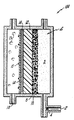
- The drawing is a diagrammatic representation of an evaporatively cooled fuel cell.
- One embodiment of the fuel cell of the
present invention 100 is shown in the drawing (not to scale). The ion exchange membrane 12, the cathode 14 and the electrically conductivewet proofing 16 are conventional. In the pictured embodiment, liquid water is introduced through the water inlet 2 and then formed into a fineliquid water mist 3 by aspirator means 4. Theliquid water mist 3 is introduced onto the anode 6 and directed to the ion exchange membrane 12 by the desiccant 8 (in powdered form) which has been applied to the catalyst 10. All of the water in the cathode 14, including theliquid water mist 3 which has been transported through the ion exchange membrane 12 and the product water formed at the cathode 14, is available to be evaporated and is shown in the drawing as excessliquid water 15 and evaporated water 17. Electrically conductivewet proofing 16 discourages water buildup on the cathode electrode surface. Both excessliquid water 15 and evaporated water 17 may be removed from thefuel cell 100 by the blowing air or oxygen gas reactant entering throughinlet 18. - Liquid water may be supplied by any conventional methods or techniques. The water must be supplied in the liquid phase rather than the vapor phase because without a phase change no heat will be lost from the system and the evaporation of the water will not cool the cell. The amount of liquid water introduced is critical to the invention because the cell will protonically pump up to only about seven times the number of water molecules per hydrogen atom (i.e., 2H+ protons). Therefore, the amount of water introduced into the system must be controlled to effect cooling of the fuel cell and yet prevent flooding of the anode.
- The amount of liquid water can be controlled in a variety of ways. For example, a simple valve could be used or the aspirator means could control the amount of liquid water introduced as well as aspirating the water. Additionally, a modest recirculation of the fuel is possible. This recirculation will help control the introduction rate by improved distribution of the mist over the entire anode surface area.
- The amount of liquid water which is required to be introduced into the anode to effect the cell cooling depends upon the efficiency at which the cell is running. By the efficiency it is meant the ratio of the electrical power produced to the higher heating value of the hydrogen fuel. The lower the efficiency of the fuel cell, the more waste heat generated, and therefore, the greater the amount of liquid water which must be introduced in order to cool the fuel cell. For example, running a cell at about 50% efficiency requires the introduction of an amount of liquid water equal to about two and a half times the amount of product water formed, whereas, running the cell at 30% efficiency requires introducing almost four times the amount of product water formed. Typically, the amount of water introduced into the anode will be greater than two times, but less than seven times the product water production rate.
- The aspirator can be any means which will form small droplets of water from supplied liquid water. The mist may be introduced into the anode directly or it may be introduced into the anode indirectly by first injecting the mist into the fuel stream. Preferably, the aspirator means will also function to control the critical amount of liquid water entering the anode, although other means for controlling the amount of liquid water could be used instead of the aspirator. The liquid water is introduced into the anode in mist form rather than in a stream to give better distribution of the water in the anode, thereby helping to prevent local area flooding. Additionally, the mist is beneficial because the ion exchange membrane water gradient can be essentially eliminated. The water gradient is due to the electroosmosis with a slower back migration rate of the water molecules in the ion exchange membrane, leaving the anode side of the ion exchange membrane drier than the cathode side of the ion exchange membrane. Because a drier ion exchange membrane has more internal resistance, eliminating the water gradient will lead to increased current density capability and further increases in power density. The Sonotek Corporation produces an ultrasonic nozzle which appears to be useful as an aspirator in this invention. The nozzle creates a very fine mist. In the practice of this invention, the finer the mist the better to discourage water flooding.
- The desiccant material can be any material which will transport the liquid water mist from the surface of the anode to the ion exchange membrane and help prevent local area flooding. The desiccant material is preferably made of a material similar to the material of which an ion exchange membrane is made. For example, a material produced by E.I. Dupont DeNemours Company and marketed under the trademark Nafion® would function well as a desiccant. The desiccant material can be applied either in liquid or powdered form. It is preferred that the desiccant used should not contaminate the membrane or there will be decreases in cell performance.
- The amount of desiccant should be selected so as to maximize liquid water transport while minimizing interference with electron transport. Typically, the amount of desiccant material used is about 5 percent to about 50 percent of the catalyst.
- The desiccant material can be applied to the anode in any way that allows transport of the liquid water mist to the ion exchange membrane surface. Preferably, a thin film coating of the desiccant (liquified membrane) is brushed onto the catalyst and platinum cells in the anode compartment. Other methods for placement of desiccant into the anode are as powders mixed with the catalysts or as a liquid by a spray technique.
- The desiccant is important for two reasons: it transports the water from the anode to the ion exchange membrane and it helps prevent local area flooding. The desiccant is hydrophilic and will absorb the liquid water mist. This water will quickly travel along the path of the desiccant and be deposited on the ion exchange membrane surface. This provides an additional benefit of keeping the ion exchange membrane wet and increasing current density capability. The liquid water mist is carried through the ion exchange membrane by electroosmosis, reappears in the cathode and then passes through the wet proofing and at least a portion is evaporated.
- The second important reason for the desiccant is to help prevent local area flooding. Flooding of the anode as a whole, is prevented by controlling the amount of water introduced into the anode. However, even with controlling the total amount of water introduced into the anode certain local areas would probably be flooded because of inconsistent distribution of the liquid water within the anode. This distribution is helped by both aspirating the liquid water into a mist and then having the desiccant material immediately absorbing and transporting the liquid water mist, thereby discouraging local area flooding.
- The ion exchange membrane is a conventional electrolyte. Nafion™ ion exchange membrane supplied by the E.I. DuPont DeNemours Company can be used in the invention as well as other membranes such as those made by Dow Chemical Corporation. It is not necessary that the ion exchange membrane be made of the same material as that of the desiccant, however, the ion exchange membrane should be the sole electrolyte. Using other electrolytes such as a liquid acid electrolyte in this invention is not desirable because the acid concentration would be difficult to maintain because of the added water. Also, with liquid acid electrolyte maintenance of an evaporation rate which is similar to the sum of the product water rate and the introduction rate of water would be necessary. The present invention overcomes these problems using an ion exchange membrane electrolyte; therefore, only the introduction rate of the supplied liquid water must be controlled.
- The cathode electrode of the fuel cell can be entirely conventional for these ion exchange fuel cells. Typically, these cathodes include a catalyst dispursed on a substrate. A most common cathode is formed of a platinum catalyst and a fluorocarbon substrate. Conventional wet proofing is also desirable to allow the oxygen access to the cathode without having to permeate water that has built up on the cathode surface.
- The cell could be used anywhere that a large, very efficient power to weight ratio is required or desired. For example, it could be used in such devices as spacecraft, submarines or ground vehicles. Evaporation is the most effective way of heat removal. The main advantage in using this type of fuel cell, is that it removes heat effectively. Because of the evaporative cooling of the fuel cell, the number of chambers in the fuel cell is reduced from three chambers to two chambers. The elimination of the cooling chamber creates a fuel cell which can be packed more efficiently. The high packing density results in a stack which produces a great amount of power for its size.
Claims (8)
Applications Claiming Priority (2)
| Application Number | Priority Date | Filing Date | Title |
|---|---|---|---|
| US76970 | 1987-07-23 | ||
| US07/076,970 US4795683A (en) | 1987-07-23 | 1987-07-23 | High power density evaporatively cooled ion exchange membrane fuel cell |
Publications (3)
| Publication Number | Publication Date |
|---|---|
| EP0301757A2 EP0301757A2 (en) | 1989-02-01 |
| EP0301757A3 EP0301757A3 (en) | 1989-04-05 |
| EP0301757B1 true EP0301757B1 (en) | 1992-03-11 |
Family
ID=22135329
Family Applications (1)
| Application Number | Title | Priority Date | Filing Date |
|---|---|---|---|
| EP88306661A Expired - Lifetime EP0301757B1 (en) | 1987-07-23 | 1988-07-20 | High power density evaporatively cooled ion exchange membrane fuel cell |
Country Status (5)
| Country | Link |
|---|---|
| US (1) | US4795683A (en) |
| EP (1) | EP0301757B1 (en) |
| JP (1) | JPH01140562A (en) |
| CA (1) | CA1297940C (en) |
| DE (1) | DE3869009D1 (en) |
Cited By (1)
| Publication number | Priority date | Publication date | Assignee | Title |
|---|---|---|---|---|
| DE10104246C1 (en) * | 2001-01-31 | 2002-06-06 | Zsw | Fuel cell e.g. for electric traction drive, incorporates dampening of process gas used for operation of fuel cell |
Families Citing this family (50)
| Publication number | Priority date | Publication date | Assignee | Title |
|---|---|---|---|---|
| DE3738370C1 (en) * | 1987-11-12 | 1989-04-13 | Dornier System Gmbh | Electrochemical cell with immobile electrolyte |
| US4824741A (en) * | 1988-02-12 | 1989-04-25 | International Fuel Cells Corporation | Solid polymer electrolyte fuel cell system with porous plate evaporative cooling |
| US4865926A (en) * | 1988-08-24 | 1989-09-12 | International Fuel Cells Corporation | Hydrogen fuel reforming in a fog cooled fuel cell power plant assembly |
| US4994331A (en) * | 1989-08-28 | 1991-02-19 | International Fuel Cells Corporation | Fuel cell evaporative cooling using fuel as a carrier gas |
| JP3106554B2 (en) * | 1990-08-03 | 2000-11-06 | 富士電機株式会社 | Solid polymer electrolyte fuel cell and method for supplying water and gas contained in the membrane |
| US5366818A (en) * | 1991-01-15 | 1994-11-22 | Ballard Power Systems Inc. | Solid polymer fuel cell systems incorporating water removal at the anode |
| US5547776A (en) * | 1991-01-15 | 1996-08-20 | Ballard Power Systems Inc. | Electrochemical fuel cell stack with concurrently flowing coolant and oxidant streams |
| US5260143A (en) * | 1991-01-15 | 1993-11-09 | Ballard Power Systems Inc. | Method and apparatus for removing water from electrochemical fuel cells |
| US5318863A (en) * | 1991-12-17 | 1994-06-07 | Bcs Technology, Inc. | Near ambient, unhumidified solid polymer fuel cell |
| US5242764A (en) * | 1991-12-17 | 1993-09-07 | Bcs Technology, Inc. | Near ambient, unhumidified solid polymer fuel cell |
| DE4318818C2 (en) * | 1993-06-07 | 1995-05-04 | Daimler Benz Ag | Method and device for providing conditioned process air for air-breathing fuel cell systems |
| US5773160A (en) * | 1994-06-24 | 1998-06-30 | Ballard Power Systems Inc. | Electrochemical fuel cell stack with concurrent flow of coolant and oxidant streams and countercurrent flow of fuel and oxidant streams |
| EP0755576B1 (en) * | 1994-10-18 | 2008-03-05 | The University Of Southern California | Organic fuel cell, and methods of operation thereof and manufacture of electrode therefor |
| JP3203150B2 (en) * | 1995-05-18 | 2001-08-27 | 三洋電機株式会社 | Polymer electrolyte fuel cell and polymer electrolyte fuel cell system |
| DE19641143A1 (en) * | 1995-10-05 | 1997-04-17 | Magnet Motor Gmbh | Polymer electrolyte fuel cell |
| WO1998045889A1 (en) * | 1997-04-10 | 1998-10-15 | Magnet-Motor Gesellschaft Für Magnetmotorische Technik Mbh | Cooling and wetting polymer-electrolyte fuel cells |
| JP4543440B2 (en) | 1997-12-22 | 2010-09-15 | 株式会社エクォス・リサーチ | Water direct injection fuel cell system |
| DE19859485A1 (en) * | 1997-12-22 | 1999-06-24 | Equos Research Kk | Fuel cell system |
| JPH11317236A (en) | 1997-12-22 | 1999-11-16 | Aqueous Reserch:Kk | Fuel cell system |
| JP4501165B2 (en) * | 1997-12-22 | 2010-07-14 | 株式会社エクォス・リサーチ | Fuel cell system for vehicles |
| US6087029A (en) * | 1998-01-06 | 2000-07-11 | Aer Energy Resources, Inc. | Water recovery using a bi-directional air exchanger for a metal-air battery |
| JP4131038B2 (en) * | 1998-06-26 | 2008-08-13 | 株式会社エクォス・リサーチ | Fuel cell system |
| JP4682386B2 (en) * | 1999-02-23 | 2011-05-11 | トヨタ自動車株式会社 | Fuel cell system |
| IT1312198B1 (en) | 1999-04-21 | 2002-04-09 | De Nora Spa | COOLED FUEL CELL BY DIRECT INJECTION OF AQUALIQUIDA |
| GB9915925D0 (en) * | 1999-07-08 | 1999-09-08 | Univ Loughborough | Flow field plates |
| US6316137B1 (en) | 1999-08-27 | 2001-11-13 | Plug Power Inc. | Cooling a fuel cell stack |
| JP4686814B2 (en) | 1999-11-17 | 2011-05-25 | 株式会社エクォス・リサーチ | Fuel cell device |
| JP4439076B2 (en) * | 2000-03-31 | 2010-03-24 | 株式会社東芝 | Polymer electrolyte fuel cell stack |
| US6468682B1 (en) | 2000-05-17 | 2002-10-22 | Avista Laboratories, Inc. | Ion exchange membrane fuel cell |
| US7326480B2 (en) | 2000-05-17 | 2008-02-05 | Relion, Inc. | Fuel cell power system and method of controlling a fuel cell power system |
| US6489049B1 (en) * | 2000-07-03 | 2002-12-03 | Johnson Electro Mechanical Systems, Llc | Electrochemical conversion system |
| US6779351B2 (en) * | 2000-09-27 | 2004-08-24 | Idalex Technologies, Inc. | Fuel cell systems with evaporative cooling and methods for humidifying and adjusting the temperature of the reactant streams |
| DE10052606A1 (en) * | 2000-10-24 | 2002-08-08 | Xcellsis Gmbh | Apparatus used in fuel cell systems recycles a liquid condensed on the inner wall of a tube having capillaries, through which a gas passes, back into the gas stream |
| JP3900952B2 (en) * | 2001-04-11 | 2007-04-04 | 株式会社デンソー | Fuel cell system |
| US6630259B2 (en) | 2001-05-23 | 2003-10-07 | Avista Laboratories, Inc. | Fuel cell power system performing AC inversion, method of distributing AC power, and method of operating a fuel cell power system |
| US6497974B2 (en) | 2001-05-23 | 2002-12-24 | Avista Laboratories, Inc. | Fuel cell power system, method of distributing power, and method of operating a fuel cell power system |
| WO2003009411A1 (en) * | 2001-07-18 | 2003-01-30 | Kabushiki Kaisha Toshiba | Solid-state polymer type fuel cell stack |
| US6532792B2 (en) | 2001-07-26 | 2003-03-18 | Avista Laboratories, Inc. | Method of compensating a MOS gas sensor, method of manufacturing a MOS gas sensor, MOS gas sensor, and fuel cell system |
| US20030118880A1 (en) * | 2001-11-28 | 2003-06-26 | Ballard Power Systems | Evaporative edge cooling of a fuel cell |
| AU2003224627A1 (en) * | 2002-02-22 | 2003-09-09 | Idalex Technologies, Inc. | Fuel cell systems with evaporative cooling and methods for humidifying and adjusting the temperature of the reactant streams |
| US20050221136A1 (en) * | 2002-04-05 | 2005-10-06 | Canon Kabushiki Kaisha | Charger, fuel cell system, and method of charring fuel cell system |
| US7036466B2 (en) * | 2004-03-10 | 2006-05-02 | General Motors Corporation | Thermal management system and method for vehicle electrochemical engine |
| GB0410850D0 (en) * | 2004-05-14 | 2004-06-16 | Cambridge Consultants | Cooling |
| US8852819B2 (en) * | 2009-06-05 | 2014-10-07 | Blackberry Limited | System and method for managing fuel cell operating conditions in a mobile communication device |
| EP2270913B1 (en) * | 2009-06-05 | 2011-11-09 | Research In Motion Limited | System and method for managing fuel cell operating conditions in a mobile communication device |
| JP5135370B2 (en) * | 2010-03-17 | 2013-02-06 | 株式会社日立製作所 | Polymer electrolyte fuel cell |
| US9441542B2 (en) | 2011-09-20 | 2016-09-13 | General Electric Company | Ultrasonic water atomization system for gas turbine inlet cooling and wet compression |
| DE102014221241A1 (en) | 2014-10-20 | 2016-04-21 | Volkswagen Aktiengesellschaft | Humidifying device for a fuel cell system and fuel cell system |
| DE102014225589A1 (en) | 2014-12-11 | 2016-06-16 | Volkswagen Ag | Method for operating a fuel cell system and fuel cell system |
| DE102016111562A1 (en) * | 2016-06-23 | 2017-12-28 | Volkswagen Ag | Filter medium and filter device with ion exchange function |
Family Cites Families (12)
| Publication number | Priority date | Publication date | Assignee | Title |
|---|---|---|---|---|
| NL259578A (en) * | 1959-12-31 | 1900-01-01 | ||
| FR1331774A (en) * | 1961-08-18 | 1963-07-05 | Thomson Houston Comp Francaise | Fuel cells |
| US3172784A (en) * | 1961-08-18 | 1965-03-09 | Gen Electric | Methods and apparatus for removing heat and water from a fuel cell |
| NL6515821A (en) * | 1965-12-06 | 1967-06-07 | ||
| US3483036A (en) * | 1966-08-19 | 1969-12-09 | Harry P Gregor | Fuel cell with ion exchange electrolyte |
| US3528858A (en) * | 1968-12-04 | 1970-09-15 | Gen Electric | Sulfonated aryl-substituted polyphenylene ether ion exchange membranes |
| US3709736A (en) * | 1970-08-17 | 1973-01-09 | Engelhard Min & Chem | Fuel cell system comprising noncirculating,counter-current gas flow means |
| US3761316A (en) * | 1971-03-29 | 1973-09-25 | United Aircraft Corp | Fuel cell with evaporative cooling |
| US4032694A (en) * | 1976-08-26 | 1977-06-28 | General Electric Company | Fuel cell with hydronium beta-alumina electrolyte |
| DE3321984A1 (en) * | 1982-06-23 | 1983-12-29 | General Electric Co., Schenectady, N.Y. | Fuel cell battery with improved membrane cooling |
| US4596748A (en) * | 1984-04-11 | 1986-06-24 | United Technologies Corporation | Method for replacing lost electrolyte in fuel cells |
| US4530886A (en) * | 1984-12-06 | 1985-07-23 | United Technologies Corporation | Process for humidifying a gaseous fuel stream |
-
1987
- 1987-07-23 US US07/076,970 patent/US4795683A/en not_active Expired - Lifetime
-
1988
- 1988-07-20 EP EP88306661A patent/EP0301757B1/en not_active Expired - Lifetime
- 1988-07-20 DE DE8888306661T patent/DE3869009D1/en not_active Expired - Fee Related
- 1988-07-21 CA CA000572445A patent/CA1297940C/en not_active Expired - Fee Related
- 1988-07-22 JP JP63183379A patent/JPH01140562A/en active Pending
Cited By (1)
| Publication number | Priority date | Publication date | Assignee | Title |
|---|---|---|---|---|
| DE10104246C1 (en) * | 2001-01-31 | 2002-06-06 | Zsw | Fuel cell e.g. for electric traction drive, incorporates dampening of process gas used for operation of fuel cell |
Also Published As
| Publication number | Publication date |
|---|---|
| EP0301757A2 (en) | 1989-02-01 |
| DE3869009D1 (en) | 1992-04-16 |
| EP0301757A3 (en) | 1989-04-05 |
| CA1297940C (en) | 1992-03-24 |
| US4795683A (en) | 1989-01-03 |
| JPH01140562A (en) | 1989-06-01 |
Similar Documents
| Publication | Publication Date | Title |
|---|---|---|
| EP0301757B1 (en) | High power density evaporatively cooled ion exchange membrane fuel cell | |
| US4973530A (en) | Fuel cell water transport | |
| CA2146325C (en) | Solid polymer fuel cell systems incorporating water removal at the anode | |
| KR102569814B1 (en) | PEM Water Electrolyzer System, PEM Water Electrolyzer Cells, Stacks and Methods of Producing Hydrogen in the System | |
| US6723461B2 (en) | Water management system for fuel cell | |
| US7172827B2 (en) | Fuel cells with integrated humidification and method for humidifying fuel cell process gas | |
| US6682839B2 (en) | Method and apparatus for controlling the temperature within an electrochemical fuel cell | |
| JP2003505824A (en) | Humidifier for fuel cell power equipment | |
| JP2003515233A (en) | Direct antifreeze-cooled fuel cell power equipment | |
| WO2001047052A1 (en) | Coolant treatment system for a direct antifreeze cooled fuel cell assembly | |
| US6368737B1 (en) | Subambient pressure coolant loop for a fuel cell power plant | |
| US20090053568A1 (en) | Evaporative Cooling of Fuel Cells Employing Antifreeze Solution | |
| KR20050007645A (en) | Fuel cell system | |
| JPH11135132A (en) | Solid polymer electrolyte fuel cell | |
| US7790330B2 (en) | Polymer fuel cell structure | |
| EP1294037B1 (en) | A fuel cell stack and a method of supplying reactant gases to the fuel cell stack | |
| US6350535B1 (en) | Mist evaporation system for fuel cell hydration | |
| JP2004529458A (en) | Method for improving the moisture balance of a fuel cell | |
| US20050112437A1 (en) | Cathode saturation arrangement for fuel cell power plant | |
| JP2006310110A (en) | On-vehicle fuel cell system | |
| US20060177723A1 (en) | Fuel cell stack | |
| WO2001028022A1 (en) | Method and apparatus for managing hydration level of fuel cell electrolyte | |
| JPH0379825B2 (en) |
Legal Events
| Date | Code | Title | Description |
|---|---|---|---|
| PUAI | Public reference made under article 153(3) epc to a published international application that has entered the european phase |
Free format text: ORIGINAL CODE: 0009012 |
|
| AK | Designated contracting states |
Kind code of ref document: A2 Designated state(s): BE DE FR GB IT NL SE |
|
| PUAL | Search report despatched |
Free format text: ORIGINAL CODE: 0009013 |
|
| AK | Designated contracting states |
Kind code of ref document: A3 Designated state(s): BE DE FR GB IT NL SE |
|
| 17P | Request for examination filed |
Effective date: 19890918 |
|
| 17Q | First examination report despatched |
Effective date: 19910311 |
|
| GRAA | (expected) grant |
Free format text: ORIGINAL CODE: 0009210 |
|
| AK | Designated contracting states |
Kind code of ref document: B1 Designated state(s): BE DE FR GB IT NL SE |
|
| ITF | It: translation for a ep patent filed |
Owner name: JACOBACCI & PERANI S.P.A. |
|
| ET | Fr: translation filed | ||
| REF | Corresponds to: |
Ref document number: 3869009 Country of ref document: DE Date of ref document: 19920416 |
|
| PLBE | No opposition filed within time limit |
Free format text: ORIGINAL CODE: 0009261 |
|
| STAA | Information on the status of an ep patent application or granted ep patent |
Free format text: STATUS: NO OPPOSITION FILED WITHIN TIME LIMIT |
|
| 26N | No opposition filed | ||
| PGFP | Annual fee paid to national office [announced via postgrant information from national office to epo] |
Ref country code: FR Payment date: 19940609 Year of fee payment: 7 |
|
| PGFP | Annual fee paid to national office [announced via postgrant information from national office to epo] |
Ref country code: SE Payment date: 19940615 Year of fee payment: 7 |
|
| PGFP | Annual fee paid to national office [announced via postgrant information from national office to epo] |
Ref country code: BE Payment date: 19940705 Year of fee payment: 7 |
|
| PGFP | Annual fee paid to national office [announced via postgrant information from national office to epo] |
Ref country code: NL Payment date: 19940731 Year of fee payment: 7 |
|
| EAL | Se: european patent in force in sweden |
Ref document number: 88306661.5 |
|
| PG25 | Lapsed in a contracting state [announced via postgrant information from national office to epo] |
Ref country code: SE Effective date: 19950721 |
|
| PG25 | Lapsed in a contracting state [announced via postgrant information from national office to epo] |
Ref country code: BE Effective date: 19950731 |
|
| BERE | Be: lapsed |
Owner name: UNITED TECHNOLOGIES CORP. Effective date: 19950731 |
|
| PG25 | Lapsed in a contracting state [announced via postgrant information from national office to epo] |
Ref country code: NL Effective date: 19960201 |
|
| NLV4 | Nl: lapsed or anulled due to non-payment of the annual fee |
Effective date: 19960201 |
|
| EUG | Se: european patent has lapsed |
Ref document number: 88306661.5 |
|
| PG25 | Lapsed in a contracting state [announced via postgrant information from national office to epo] |
Ref country code: FR Effective date: 19960430 |
|
| REG | Reference to a national code |
Ref country code: FR Ref legal event code: ST |
|
| REG | Reference to a national code |
Ref country code: FR Ref legal event code: ST |
|
| REG | Reference to a national code |
Ref country code: FR Ref legal event code: ST |
|
| PGFP | Annual fee paid to national office [announced via postgrant information from national office to epo] |
Ref country code: GB Payment date: 20010626 Year of fee payment: 14 |
|
| REG | Reference to a national code |
Ref country code: GB Ref legal event code: IF02 |
|
| PGFP | Annual fee paid to national office [announced via postgrant information from national office to epo] |
Ref country code: DE Payment date: 20020718 Year of fee payment: 15 |
|
| PG25 | Lapsed in a contracting state [announced via postgrant information from national office to epo] |
Ref country code: GB Free format text: LAPSE BECAUSE OF NON-PAYMENT OF DUE FEES Effective date: 20020720 |
|
| GBPC | Gb: european patent ceased through non-payment of renewal fee |
Effective date: 20020720 |
|
| PG25 | Lapsed in a contracting state [announced via postgrant information from national office to epo] |
Ref country code: DE Free format text: LAPSE BECAUSE OF NON-PAYMENT OF DUE FEES Effective date: 20040203 |
|
| PG25 | Lapsed in a contracting state [announced via postgrant information from national office to epo] |
Ref country code: IT Free format text: LAPSE BECAUSE OF NON-PAYMENT OF DUE FEES;WARNING: LAPSES OF ITALIAN PATENTS WITH EFFECTIVE DATE BEFORE 2007 MAY HAVE OCCURRED AT ANY TIME BEFORE 2007. THE CORRECT EFFECTIVE DATE MAY BE DIFFERENT FROM THE ONE RECORDED. Effective date: 20050720 |