EP0297227A2 - Machine unit having retaining device using static electricity - Google Patents
Machine unit having retaining device using static electricity Download PDFInfo
- Publication number
- EP0297227A2 EP0297227A2 EP88105806A EP88105806A EP0297227A2 EP 0297227 A2 EP0297227 A2 EP 0297227A2 EP 88105806 A EP88105806 A EP 88105806A EP 88105806 A EP88105806 A EP 88105806A EP 0297227 A2 EP0297227 A2 EP 0297227A2
- Authority
- EP
- European Patent Office
- Prior art keywords
- electrodes
- pair
- attraction
- electrostatic
- unit according
- Prior art date
- Legal status (The legal status is an assumption and is not a legal conclusion. Google has not performed a legal analysis and makes no representation as to the accuracy of the status listed.)
- Granted
Links
Images

Classifications
-
- B—PERFORMING OPERATIONS; TRANSPORTING
- B23—MACHINE TOOLS; METAL-WORKING NOT OTHERWISE PROVIDED FOR
- B23Q—DETAILS, COMPONENTS, OR ACCESSORIES FOR MACHINE TOOLS, e.g. ARRANGEMENTS FOR COPYING OR CONTROLLING; MACHINE TOOLS IN GENERAL CHARACTERISED BY THE CONSTRUCTION OF PARTICULAR DETAILS OR COMPONENTS; COMBINATIONS OR ASSOCIATIONS OF METAL-WORKING MACHINES, NOT DIRECTED TO A PARTICULAR RESULT
- B23Q3/00—Devices holding, supporting, or positioning work or tools, of a kind normally removable from the machine
- B23Q3/15—Devices for holding work using magnetic or electric force acting directly on the work
- B23Q3/154—Stationary devices
-
- B—PERFORMING OPERATIONS; TRANSPORTING
- B23—MACHINE TOOLS; METAL-WORKING NOT OTHERWISE PROVIDED FOR
- B23Q—DETAILS, COMPONENTS, OR ACCESSORIES FOR MACHINE TOOLS, e.g. ARRANGEMENTS FOR COPYING OR CONTROLLING; MACHINE TOOLS IN GENERAL CHARACTERISED BY THE CONSTRUCTION OF PARTICULAR DETAILS OR COMPONENTS; COMBINATIONS OR ASSOCIATIONS OF METAL-WORKING MACHINES, NOT DIRECTED TO A PARTICULAR RESULT
- B23Q3/00—Devices holding, supporting, or positioning work or tools, of a kind normally removable from the machine
- B23Q3/15—Devices for holding work using magnetic or electric force acting directly on the work
-
- B—PERFORMING OPERATIONS; TRANSPORTING
- B25—HAND TOOLS; PORTABLE POWER-DRIVEN TOOLS; MANIPULATORS
- B25B—TOOLS OR BENCH DEVICES NOT OTHERWISE PROVIDED FOR, FOR FASTENING, CONNECTING, DISENGAGING OR HOLDING
- B25B11/00—Work holders not covered by any preceding group in the subclass, e.g. magnetic work holders, vacuum work holders
- B25B11/002—Magnetic work holders
-
- H—ELECTRICITY
- H02—GENERATION; CONVERSION OR DISTRIBUTION OF ELECTRIC POWER
- H02N—ELECTRIC MACHINES NOT OTHERWISE PROVIDED FOR
- H02N13/00—Clutches or holding devices using electrostatic attraction, e.g. using Johnson-Rahbek effect
-
- Y—GENERAL TAGGING OF NEW TECHNOLOGICAL DEVELOPMENTS; GENERAL TAGGING OF CROSS-SECTIONAL TECHNOLOGIES SPANNING OVER SEVERAL SECTIONS OF THE IPC; TECHNICAL SUBJECTS COVERED BY FORMER USPC CROSS-REFERENCE ART COLLECTIONS [XRACs] AND DIGESTS
- Y10—TECHNICAL SUBJECTS COVERED BY FORMER USPC
- Y10T—TECHNICAL SUBJECTS COVERED BY FORMER US CLASSIFICATION
- Y10T279/00—Chucks or sockets
- Y10T279/23—Chucks or sockets with magnetic or electrostatic means
Definitions
- This invention relates to a machine unit having a retaining means using static electricity and, more particularly, to a machine unit having a retaining means capable of continuously and newly generating a large attraction force from a current supplied at a low voltage without being affected by temperature, humidity and other factors and capable of stably retaining an attracted object at a desired position on the machine unit.
- a type of electrostatic retention means for attracting and retaining an object by using the Coulomb force of static electricity operates in such a manner that positive and negative charges are supplied to a pair of electrodes so as to induce static electricity in an attraction mechanism, and an object is attracted and retained by an electrostatic attraction force of this attraction mechanism.
- This type of electrostatic retention means has been applied to various machines or installations in various industrial fields. For example, it is used as an original holder portion of a copier or a portion of a conveyor system adapted to retain an object to be transported.
- the conventional electrostatic retention means also tends to be affected by temperature T, humidity H, and so forth, as shown in the attached table.
- the conventional retention means cannot stably retain the attracted object when the ambient temperature is low because the attraction force abruptly decreases if the temperature is reduced.
- the attached table shows results of an experiment in which a sheet of paper of A-4 size attracted to the surface of the attraction mechanism is drawn by a force applied parallel to this surface at an ambient temperature T (humidity H). Values shown in this table represents a force F required to start separation of the sheet of paper in this manner.
- the conventional electrostatic retention means it is necessary for the conventional electrostatic retention means to be manufactured by carefully selecting specific materials in consideration of the electrical characteristics of the attraction mechanism in order to cope with the above-mentioned problems.
- the range of selection of materials is therefore narrow, and this increases the manufacturing cost.
- a conventional electrostatic retention means of the above-described type is provided in a machine unit such as a copier, it is difficult to optimize the functions of the machine unit since the retention means cannot stably attract and retain an object at a desired position.
- the present invention provides a machine unit provided with an electrostatic retention means disposed at a desired position, the electrostatic retention means having: a pair of electrodes; an attraction mechanism in which static electricity is induced so as to generate an electrostatic attraction force and which attracts and retains an object by this electrostatic attraction force; and a power source circuit for supplying positive and negative charges to the pair of electrodes while changing the polarity thereof.
- the electrostatic retention means disposed at a desired position in a machine unit can continuously and newly generate a large attraction force while preventing reduction in the attraction force due to electrification of the ambient atmosphere or due to separation of an attracted object when the power supply circuit supplies positive and negative electric charges to the pair of electrode terminals while changing the polarity thereof.
- the attracted object can therefore be readily separated from a desired portion of the machine unit or can be securely and stably retained on a desired portion of the machine unit.
- Fig. 1 denotes an electrostatic retention means
- 4 and 6 denote electrodes
- 8 denotes an attraction member
- 10 denotes a power source circuit.
- the pair of electrodes 4 and 6, for example, are comb shaped with the toothlike elements thereof being alternately disposed. These electrodes are supplied with charges from the power source circuit 10.
- An object 12 to be attracted is brought into contact with the attraction member 8 in which static electricity is induced by the pair of electrodes 4 and 6. Electric charges are thereby produced by electrostatic induction at portions of the object 12 which face the electrodes 4 and 6. These electric charges have polarities opposite to those of the corresponding electrodes.
- Electrostatic attraction occurs between the charges produced on the object 12 and the charges on the electrodes 4 and 6, thereby attracting the object 12 to the surface of the attraction member 8 so that the object 12 is retained thereon.
- the power source circuit 10 supplies positive and negative electric charges to the pair of electrodes 4 and 6 while changing the polarity thereof. That is, positive charge is first supplied to the electrode 4 while negative charge is supplied to the electrode 6. The supply of charge is temporarily stopped and negative charge is thereafter supplied to the electrode 4 and positive charge is supplied to the electrode 6. Next, positive charge is again supplied to the electrode 4 while negative charge is again supplied to the electrode 6, as in the case of the first operation.
- the power source circuit 10 thus operates to supply alternately changing positive and negative charges to the electrodes 4 and 6.
- the power source circuit 10 is constituted by a power source 14 for supplying direct current (i.e. DC) power, and a changeover or switching means 16 for changing over the polarity of the DC power from the power source 14 so as to supply alternately changing positive and negative charges to the pair of electrodes 4 and 6.
- the electrostatic retention means 2 static electricity is induced in the attraction member 8, as positive and negative charges are supplied from the power source 14 to the electrodes 4 and 6 while the polarity of DC power from the power source 14 is changed by the changeover switch 16.
- the object 12 is brought into contact with the attraction member 8, it is attracted and retained by an attraction force produced by electric charges of different polarities on the electrodes and the object.
- the attracted object 12 can be retained securely and stably even if it is not flatly placed, that is, it is inclined or standing vertically.
- a special material such as the one used by the conventional method to form the retaining means since a large attraction force is continuously and newly provided.
- the device in accordance with the present invention can be manufactured by selecting materials within a wide selection range and is therefore advantageous in terms of manufacturing cost.
- Fig. 2 shows an electrostatic chuck device 18-1 provided as a machine or holding unit.
- the electrostatic chuck device 18-1 is adapted to retain a semiconductor wafer 12-1 provided as the object 12 to be attracted, and the above-described electrostatic retention means 2 is applied to this device in such a manner that the electrodes 4 and 6 and the attraction member 8 are disposed on a base 20 at a desired position with an insulating layer 22 interposed therebetween.
- the semiconductor wafer 12-1 can be stably retained on the attraction member 8 by a large attraction force which is continuously and newly provided by supplying positive and negative charges from the power source circuit 10 to the electrodes 4 and 6 while sequentially changing the polarity thereof with elapse of time.
- the thus constructed electrostatic chuck device 18-1 enables the semiconductor wafer 12-1 to be retained while the position thereof is determined with an improved accuracy, thereby reducing the number of resultant defective products.
- Fig. 3 shows another type of electrostatic chuck device 18-2 which is provided with a conductive member 24 disposed on the base 20 at a desired position with the insulating layer 22 interposed therebetween.
- the conductive member 24 serves as one of the pair of electrodes.
- a semiconductor wafer 12-2 provided as the object 12 to be attracted is used as the other one of the pair of electrodes.
- the semiconductor wafer 12-2 can be directly retained more stably on the attraction member 8 by supplying positive and negative charges to the conductive member 24 and the semiconductor wafer 12-2 while changing the polarity thereof with elapse of time. In this case, the need for the provision of the comblike electrodes 4 and 6 is eliminated, thereby enabling simplification of the structure and a reduction in the manufacturing cost.
- Fig. 4 shows an electrostatic paper feeding device 18-3 provided as a machine unit.
- the electrostatic paper feeding device 18-3 is adapted to retain and feed a sheet of paper 12-3 provided as the object 12 to be attracted, and the electrostatic retention means 2 is applied to this device in such a manner that the electrodes 4 and 6 and the attraction member 8 are disposed around the surface of a rotatable feed roller 26 of the electrostatic paper feeding device 18-3.
- the sheet of paper 12-3 can be stably retained on the feed roller 26 and positively fed by virtue of a large attraction force which is continuously and newly provided by supplying positive and negative charges from the power source circuit 10 to the electrodes 4 and 6 while sequentially reversing the polarity thereof.
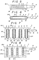
- Figs. 5 and 6 show an electrostatic conveyor 18-4 provided as a machine unit.
- the electrostatic paper feeding device 18-4 is adapted to retain and transport a transportation object 12-4 provided as the object 12 to be attracted, and the electrostatic retention means 2 is applied to this conveyor in such a manner that the electrodes 4 and 6 and the attraction member 8 are disposed on a conveyor belt 32 stretched between a pair of rollers 28 and 30.
- the transportation object 12-4 can be stably retained on the conveyor belt 32 and positively transported by virtue of a large attraction force which is continuously and newly provided by supplying positive and negative charges from the power source circuit 10 to the electrodes 4 and 6 while sequentially reversing the polarity thereof.
- the electrodes 4 and 6 are preferably of a comblike configuration with the electrodes being disposed in opposed and interfitting relationship, whereby the teethlike elements of the electrodes hence extend transversely (that is, axially) relative to the roller 26 (Fig. 4) or belt 32 (Figs. 5-6).
- the electrical charge can be supplied to the electrodes from the power source circuit 10 by conventional means, such as conventional relatively-slidable electrical contacts associated with the roller or belt.
- Fig. 7 shows an electrostatic cleaner 18-5 provided as a machine unit.
- the electrostatic cleaner 18-5 is adapted to attract and remove very small objects or particles 12-5 in the air such as particles of cement, bacteria, or dust disposed as the object 12 to be attracted.
- the electrostatic retention means 2 is applied to this device in such a manner that the electrodes 4 and 6 and the attraction member 8 are disposed on both sides of support members 40 made of an insulating material and arranged in parallel so as to extend from an inlet section 36 to an outlet section 38 in the direction in which air flows through a main body 34 of the electrostatic cleaner 18-5.
- the cleaner 18-5 can positively attract and remove very small objects 12-5 from the air flowing from the inlet section 36 to the outlet section 38 by virtue of a large attraction force which is continuously and newly provided by supplying positive and negative charges from the power source circuit 10 to the electrodes 4 and 6 while changing the polarity thereof at predetermined periods of time, e.g., 15 minute time intervals.
- the supply of electric charge to the electrodes 4 and 6 may be interrupted for a certain period of time so as to eliminate the attraction force, thereby enabling the attraction members to be cleaned by removing small objects attracted and retained thereon.
- Fig. 8 shows another type of electrostatic cleaner 18-6.
- Positive and negative charges are supplied from the power source circuit 10 to the electrodes 4 and 6 while periodically changing the polarity thereof. Since the range of selection of each material for forming the electrostatic retention means 2 in accordance with the present invention is wide, the attraction member 8 can be formed from a material capable of providing a high degree of rigidity. It is therefore possible to eliminate the support members 40 associated with the electrostatic cleaner 18-5. The attraction members 8 are directly supported on the main body 34 thereinside.
- the electrostatic cleaner 18-6 has a simple structure and can therefore be manufactured at a low cost, but it can positively remove very small objects 12-6.
- the time period with which the polarity of the positive and negative charges supplied to the pair of electrodes 4 and 6 is changed is set at 15 minutes. However, it is preferable to select a desired length of the period in the order of seconds, minutes or hours depending upon conditions of the ambient atmosphere such as temperature and humidity and/or other conditions including the material used to form the attraction member 8.
- the electrostatic retention means disposed at a desired position in a machine unit can continuously and newly generate a large attraction force while preventing reduction in the attraction force due to electrification of the ambient atmosphere or due to a reduction in the amount of static electricity on the attraction member caused by separation of the attracted object because the power supply circuit supplies positive and negative electric charges to the pair of electrode terminals while sequentially changing the polarity thereof at selected time intervals.
- the device in accordance with the present invention can generate a large attraction force compared with the conventional device even at a low ambient temperature without being influenced by temperature and humidity.
- the functions of the machine unit having this electrostatic retention means can be optimized by enabling the attracted object to be retained at a desired position in the above-described manner.
Abstract
Description
- This application is a continuation-in-part of my copending application Serial No. 084 447 filed August 12, 1987. The disclosure of Serial No. 084 447 is incorporated herein by reference. (JDEA-1)
- This invention relates to a machine unit having a retaining means using static electricity and, more particularly, to a machine unit having a retaining means capable of continuously and newly generating a large attraction force from a current supplied at a low voltage without being affected by temperature, humidity and other factors and capable of stably retaining an attracted object at a desired position on the machine unit.
- A type of electrostatic retention means for attracting and retaining an object by using the Coulomb force of static electricity operates in such a manner that positive and negative charges are supplied to a pair of electrodes so as to induce static electricity in an attraction mechanism, and an object is attracted and retained by an electrostatic attraction force of this attraction mechanism. This type of electrostatic retention means has been applied to various machines or installations in various industrial fields. For example, it is used as an original holder portion of a copier or a portion of a conveyor system adapted to retain an object to be transported.
- In this conventional electrostatic retention means, a current of constant polarity is continuously supplied to each of the pair of electrodes. As a current of constant polarity is continuously supplied in this manner, the ambient atmosphere around the attraction mechanism tends to be electrified so that the attraction force decreases if this electrostatic retention means operates for a long time. It is thus necessary to supply the current at a higher voltage (3,000 to 7,000 volts) in order to obtain a large attraction force.
- The conventional electrostatic retention means also tends to be affected by temperature T, humidity H, and so forth, as shown in the attached table. In particular, the conventional retention means cannot stably retain the attracted object when the ambient temperature is low because the attraction force abruptly decreases if the temperature is reduced. The attached table shows results of an experiment in which a sheet of paper of A-4 size attracted to the surface of the attraction mechanism is drawn by a force applied parallel to this surface at an ambient temperature T (humidity H). Values shown in this table represents a force F required to start separation of the sheet of paper in this manner.
- In addition, it is necessary for the conventional electrostatic retention means to be manufactured by carefully selecting specific materials in consideration of the electrical characteristics of the attraction mechanism in order to cope with the above-mentioned problems. The range of selection of materials is therefore narrow, and this increases the manufacturing cost.
- If a conventional electrostatic retention means of the above-described type is provided in a machine unit such as a copier, it is difficult to optimize the functions of the machine unit since the retention means cannot stably attract and retain an object at a desired position.
- It is therefore an object of the present invention to provide a machine unit having a retaining means which can continuously and newly generate a large attraction force from a current supplied at a low voltage without being affected by temperature, humidity and other factors, which can be manufactured at a lower cost by enabling a wide range of selection of materials, and which can stably attract and retain an object at a desired position in the machine unit, thereby optimizing the functions.
- To this end, the present invention provides a machine unit provided with an electrostatic retention means disposed at a desired position, the electrostatic retention means having: a pair of electrodes; an attraction mechanism in which static electricity is induced so as to generate an electrostatic attraction force and which attracts and retains an object by this electrostatic attraction force; and a power source circuit for supplying positive and negative charges to the pair of electrodes while changing the polarity thereof.
- In accordance with the present invention, the electrostatic retention means disposed at a desired position in a machine unit can continuously and newly generate a large attraction force while preventing reduction in the attraction force due to electrification of the ambient atmosphere or due to separation of an attracted object when the power supply circuit supplies positive and negative electric charges to the pair of electrode terminals while changing the polarity thereof. The attracted object can therefore be readily separated from a desired portion of the machine unit or can be securely and stably retained on a desired portion of the machine unit.
- The present invention will be described below in detail with reference to the accompanying drawings with respect to embodiments thereof.
-
- Fig. 1 is a plan view of an electrostatic retention means;
- Fig. 2 is a cross-sectional view of an electrostatic chuck having an electrostatic retention means;
- Fig. 3 is a cross-sectional view of another electrostatic chuck;
- Fig. 4 is a perspective view of an electrostatic paper feeding device having an electrostatic retention means;
- Figs. 5 and 6 are a perspective view and a side view of an electrostatic conveyor having an electrostatic retention means;
- Fig. 7 is a cross-sectional view of an electrostatic cleaner having an electrostatic retention means; and
- Fig. 8 is a cross-sectional view of another electrostatic cleaner.
- In Fig. 1, 2 denotes an electrostatic retention means, 4 and 6 denote electrodes, 8 denotes an attraction member, and 10 denotes a power source circuit. The pair of
electrodes power source circuit 10. Anobject 12 to be attracted is brought into contact with theattraction member 8 in which static electricity is induced by the pair ofelectrodes object 12 which face theelectrodes object 12 and the charges on theelectrodes object 12 to the surface of theattraction member 8 so that theobject 12 is retained thereon. - The
power source circuit 10 supplies positive and negative electric charges to the pair ofelectrodes electrode 4 while negative charge is supplied to theelectrode 6. The supply of charge is temporarily stopped and negative charge is thereafter supplied to theelectrode 4 and positive charge is supplied to theelectrode 6. Next, positive charge is again supplied to theelectrode 4 while negative charge is again supplied to theelectrode 6, as in the case of the first operation. Thepower source circuit 10 thus operates to supply alternately changing positive and negative charges to theelectrodes power source circuit 10 is constituted by apower source 14 for supplying direct current (i.e. DC) power, and a changeover or switching means 16 for changing over the polarity of the DC power from thepower source 14 so as to supply alternately changing positive and negative charges to the pair ofelectrodes - In the electrostatic retention means 2, static electricity is induced in the
attraction member 8, as positive and negative charges are supplied from thepower source 14 to theelectrodes power source 14 is changed by thechangeover switch 16. When theobject 12 is brought into contact with theattraction member 8, it is attracted and retained by an attraction force produced by electric charges of different polarities on the electrodes and the object. - It is thus possible to continuously and newly generate a large attraction force by supplying alternately changing positive and negative charges to the pair of
electrodes object 12 attracted by a large attraction force continuously and newly supplied. The attraction force is not reduced even if this operation is continued for a long time in an environment in which there is a possibility of electrification of the ambient atmosphere, or if the operation is performed while changing the position of theattracted object 12 or replacing it with another object. - Therefore, the
attracted object 12 can be retained securely and stably even if it is not flatly placed, that is, it is inclined or standing vertically. There is no need for a special material such as the one used by the conventional method to form the retaining means since a large attraction force is continuously and newly provided. Thus, the device in accordance with the present invention can be manufactured by selecting materials within a wide selection range and is therefore advantageous in terms of manufacturing cost. - It is thereby possible to optimize the performance of a machine or holding unit, various embodiments of which are shown in Figs. 2 to 8, by applying thereto the electrostatic retention means 2 which is capable of stably retaining the
object 12 at a desired position in the above described manner. - Fig. 2 shows an electrostatic chuck device 18-1 provided as a machine or holding unit. The electrostatic chuck device 18-1 is adapted to retain a semiconductor wafer 12-1 provided as the
object 12 to be attracted, and the above-described electrostatic retention means 2 is applied to this device in such a manner that theelectrodes attraction member 8 are disposed on abase 20 at a desired position with an insulatinglayer 22 interposed therebetween. The semiconductor wafer 12-1 can be stably retained on theattraction member 8 by a large attraction force which is continuously and newly provided by supplying positive and negative charges from thepower source circuit 10 to theelectrodes - The thus constructed electrostatic chuck device 18-1 enables the semiconductor wafer 12-1 to be retained while the position thereof is determined with an improved accuracy, thereby reducing the number of resultant defective products.
- Fig. 3 shows another type of electrostatic chuck device 18-2 which is provided with a
conductive member 24 disposed on thebase 20 at a desired position with the insulatinglayer 22 interposed therebetween. Theconductive member 24 serves as one of the pair of electrodes. A semiconductor wafer 12-2 provided as theobject 12 to be attracted is used as the other one of the pair of electrodes. - The semiconductor wafer 12-2 can be directly retained more stably on the
attraction member 8 by supplying positive and negative charges to theconductive member 24 and the semiconductor wafer 12-2 while changing the polarity thereof with elapse of time. In this case, the need for the provision of thecomblike electrodes - Fig. 4 shows an electrostatic paper feeding device 18-3 provided as a machine unit. The electrostatic paper feeding device 18-3 is adapted to retain and feed a sheet of paper 12-3 provided as the
object 12 to be attracted, and the electrostatic retention means 2 is applied to this device in such a manner that theelectrodes attraction member 8 are disposed around the surface of arotatable feed roller 26 of the electrostatic paper feeding device 18-3. The sheet of paper 12-3 can be stably retained on thefeed roller 26 and positively fed by virtue of a large attraction force which is continuously and newly provided by supplying positive and negative charges from thepower source circuit 10 to theelectrodes - Figs. 5 and 6 show an electrostatic conveyor 18-4 provided as a machine unit. The electrostatic paper feeding device 18-4 is adapted to retain and transport a transportation object 12-4 provided as the
object 12 to be attracted, and the electrostatic retention means 2 is applied to this conveyor in such a manner that theelectrodes attraction member 8 are disposed on aconveyor belt 32 stretched between a pair ofrollers conveyor belt 32 and positively transported by virtue of a large attraction force which is continuously and newly provided by supplying positive and negative charges from thepower source circuit 10 to theelectrodes - In the embodiments of Figs. 4 and 5-6, the
electrodes power source circuit 10 by conventional means, such as conventional relatively-slidable electrical contacts associated with the roller or belt. - Fig. 7 shows an electrostatic cleaner 18-5 provided as a machine unit. The electrostatic cleaner 18-5 is adapted to attract and remove very small objects or particles 12-5 in the air such as particles of cement, bacteria, or dust disposed as the
object 12 to be attracted. The electrostatic retention means 2 is applied to this device in such a manner that theelectrodes attraction member 8 are disposed on both sides ofsupport members 40 made of an insulating material and arranged in parallel so as to extend from aninlet section 36 to anoutlet section 38 in the direction in which air flows through amain body 34 of the electrostatic cleaner 18-5. The cleaner 18-5 can positively attract and remove very small objects 12-5 from the air flowing from theinlet section 36 to theoutlet section 38 by virtue of a large attraction force which is continuously and newly provided by supplying positive and negative charges from thepower source circuit 10 to theelectrodes electrodes - Fig. 8 shows another type of electrostatic cleaner 18-6. Positive and negative charges are supplied from the
power source circuit 10 to theelectrodes attraction member 8 can be formed from a material capable of providing a high degree of rigidity. It is therefore possible to eliminate thesupport members 40 associated with the electrostatic cleaner 18-5. Theattraction members 8 are directly supported on themain body 34 thereinside. The electrostatic cleaner 18-6 has a simple structure and can therefore be manufactured at a low cost, but it can positively remove very small objects 12-6. - In the case of the electrostatic cleaner 18-5 shown in Fig. 7, the time period with which the polarity of the positive and negative charges supplied to the pair of
electrodes attraction member 8.
- In accordance with the present invention, as described above, the electrostatic retention means disposed at a desired position in a machine unit can continuously and newly generate a large attraction force while preventing reduction in the attraction force due to electrification of the ambient atmosphere or due to a reduction in the amount of static electricity on the attraction member caused by separation of the attracted object because the power supply circuit supplies positive and negative electric charges to the pair of electrode terminals while sequentially changing the polarity thereof at selected time intervals.
- As shown in the attached table, the device in accordance with the present invention can generate a large attraction force compared with the conventional device even at a low ambient temperature without being influenced by temperature and humidity.
- It is thus possible to stably attract and retain an object at a desired position in the machine unit by a current supplied at a low voltage, by continuously and newly generating a large attraction force. There is no need for manufacturing the device in accordance with the present invention from a special material as in the case of the conventional device. The range of selection of materials in accordance with the present invention is wide, which is preferably in terms of manufacturing cost.
- The functions of the machine unit having this electrostatic retention means can be optimized by enabling the attracted object to be retained at a desired position in the above-described manner.
- Although a particular preferred embodiment of the invention has been disclosed in detail for illustrative purposes, it will be recognized that variations or modifications of the disclosed apparatus, including the rearrangement of parts, lie within the scope of the present invention.
Claims (13)
Priority Applications (1)
| Application Number | Priority Date | Filing Date | Title |
|---|---|---|---|
| AT88105806T ATE87150T1 (en) | 1987-04-14 | 1988-04-12 | MACHINE UNIT WITH A SUPPORT DEVICE USING STATIC ELECTRICITY. |
Applications Claiming Priority (4)
| Application Number | Priority Date | Filing Date | Title |
|---|---|---|---|
| JP62089848A JPS63257481A (en) | 1987-04-14 | 1987-04-14 | Static retainer |
| JP89848/87 | 1987-04-14 | ||
| JP58904/88 | 1988-03-12 | ||
| JP63-58904A JPH012947A (en) | 1988-03-12 | Mechanical equipment with electrostatic holding means |
Publications (3)
| Publication Number | Publication Date |
|---|---|
| EP0297227A2 true EP0297227A2 (en) | 1989-01-04 |
| EP0297227A3 EP0297227A3 (en) | 1989-05-03 |
| EP0297227B1 EP0297227B1 (en) | 1993-03-17 |
Family
ID=26399918
Family Applications (1)
| Application Number | Title | Priority Date | Filing Date |
|---|---|---|---|
| EP88105806A Expired - Lifetime EP0297227B1 (en) | 1987-04-14 | 1988-04-12 | Machine unit having retaining device using static electricity |
Country Status (4)
| Country | Link |
|---|---|
| US (1) | US4864461A (en) |
| EP (1) | EP0297227B1 (en) |
| CA (1) | CA1329638C (en) |
| DE (1) | DE3879295T2 (en) |
Cited By (9)
| Publication number | Priority date | Publication date | Assignee | Title |
|---|---|---|---|---|
| DE4015210A1 (en) * | 1989-05-12 | 1990-11-15 | Ricoh Kk | DEVICE FOR TRANSPORTING SHEET OR SIMILAR MATERIALS |
| DE19610953A1 (en) * | 1995-04-20 | 1996-10-24 | Heidelberger Druckmasch Ag | Digital precision positioning system |
| US5600530A (en) * | 1992-08-04 | 1997-02-04 | The Morgan Crucible Company Plc | Electrostatic chuck |
| DE19614717A1 (en) * | 1995-12-18 | 1997-06-19 | Heidelberger Druckmasch Ag | Methods and devices for holding substrates on a conveyor belt of a printing press |
| EP0782968A1 (en) | 1995-12-18 | 1997-07-09 | Heidelberger Druckmaschinen Aktiengesellschaft | Method and devices for holding substrates on a conveyor belt of a printing machine |
| US6092800A (en) * | 1997-06-26 | 2000-07-25 | Heidelberger Druckmaschinen Ag | Device for conveying sheets in a printing machine |
| WO2001032114A1 (en) * | 1999-11-02 | 2001-05-10 | Wizcare Ltd. | Skin-gripper |
| WO2013166324A3 (en) * | 2012-05-02 | 2014-03-13 | Sri International | Electroadhesive conveying surfaces |
| WO2014048916A1 (en) * | 2012-09-26 | 2014-04-03 | Fraunhofer-Gesellschaft zur Förderung der angewandten Forschung e.V. | Method for operating a gripping device and electrostatic gripping device |
Families Citing this family (33)
| Publication number | Priority date | Publication date | Assignee | Title |
|---|---|---|---|---|
| US5121170A (en) * | 1989-05-12 | 1992-06-09 | Ricoh Company, Ltd. | Device for transporting sheet members using an alternating voltage |
| JPH02307551A (en) * | 1989-05-20 | 1990-12-20 | Abisare:Kk | Electrostatic attraction sheet |
| US5173834A (en) * | 1989-06-02 | 1992-12-22 | Roland Dg Corporation | Electrostatic attraction apparatus |
| US5090643A (en) * | 1990-03-15 | 1992-02-25 | Spears Morton F | Force generating system |
| US5673750A (en) * | 1990-05-19 | 1997-10-07 | Hitachi, Ltd. | Vacuum processing method and apparatus |
| US5452177A (en) | 1990-06-08 | 1995-09-19 | Varian Associates, Inc. | Electrostatic wafer clamp |
| KR0165898B1 (en) * | 1990-07-02 | 1999-02-01 | 미다 가쓰시게 | Vacuum processing method and apparatus |
| JP3159727B2 (en) * | 1990-10-11 | 2001-04-23 | 株式会社リコー | Paper feeder |
| US5224693A (en) * | 1991-10-22 | 1993-07-06 | Ricoh Company, Ltd. | Multistage paper feeding/conveying apparatus and method that uses electro static forces |
| US5325120A (en) * | 1991-11-15 | 1994-06-28 | Kuehnle Manfred R | Electrostatic reproduction apparatus having a dielectric ink-phobic imaging member and field-emission write head |
| US5213349A (en) * | 1991-12-18 | 1993-05-25 | Elliott Joe C | Electrostatic chuck |
| US5211760A (en) * | 1992-04-15 | 1993-05-18 | Xerox Corporation | Paper cleaner subsystem |
| JPH0640583A (en) * | 1992-07-23 | 1994-02-15 | Ricoh Co Ltd | Paper feeding and separating device for image forming device |
| US5442429A (en) * | 1992-09-30 | 1995-08-15 | Tr Systems Inc | Precuring apparatus and method for reducing voltage required to electrostatically material to an arcuate surface |
| US5444597A (en) * | 1993-01-15 | 1995-08-22 | Blake; Julian G. | Wafer release method and apparatus |
| US5436790A (en) * | 1993-01-15 | 1995-07-25 | Eaton Corporation | Wafer sensing and clamping monitor |
| US5350428A (en) * | 1993-06-17 | 1994-09-27 | Vlsi Technology, Inc. | Electrostatic apparatus and method for removing particles from semiconductor wafers |
| ATE209573T1 (en) * | 1993-07-28 | 2001-12-15 | Canon Kk | INKJET RECORDING APPARATUS AND INKJET RECORDING METHOD |
| JP2718626B2 (en) * | 1993-11-16 | 1998-02-25 | キヤノン株式会社 | Sheet material transport device |
| US5593151A (en) * | 1994-12-19 | 1997-01-14 | Xerox Corporation | Self biasing electrostatic paper transport |
| US5818682A (en) * | 1996-08-13 | 1998-10-06 | Applied Materials, Inc. | Method and apparatus for optimizing a dechucking period used to dechuck a workpiece from an electrostatic chuck |
| US5864459A (en) * | 1996-08-14 | 1999-01-26 | Virginia Tech Intellectual Properties, Inc. | Process for providing a glass dielectric layer on an electrically conductive substrate and electrostatic chucks made by the process |
| US6309064B1 (en) * | 1997-11-20 | 2001-10-30 | Canon Kabushiki Kaisha | Printing apparatus |
| JP2002284384A (en) * | 2001-03-28 | 2002-10-03 | Canon Inc | Carrying belt, manufacturing method for the belt, and image forming device with the belt |
| DE60324749D1 (en) * | 2002-09-26 | 2009-01-02 | Canon Kk | A conveyor belt capable of attracting objects, an image forming apparatus comprising such a conveyor belt and a method of manufacturing such a conveyor belt |
| US20040066601A1 (en) * | 2002-10-04 | 2004-04-08 | Varian Semiconductor Equipment Associates, Inc. | Electrode configuration for retaining cooling gas on electrostatic wafer clamp |
| KR100545169B1 (en) * | 2003-09-03 | 2006-01-24 | 동부아남반도체 주식회사 | Electro-static chuck of semi conductor manufacturing equipment and method for chucking wafer using the same |
| CN1655022A (en) * | 2004-02-14 | 2005-08-17 | 鸿富锦精密工业(深圳)有限公司 | Substrate applying device |
| US7137496B2 (en) * | 2004-03-24 | 2006-11-21 | China Patent Investment Limited | Parallel field electrode configurations for electrorheological fluid applications |
| DE102004049329A1 (en) * | 2004-10-09 | 2006-04-20 | Windmöller & Hölscher Kg | Apparatus and method for transporting webs of material and fixing them on a counter-surface |
| DE102005053072B4 (en) * | 2005-11-04 | 2008-12-11 | Universität Bremen | Device for the electrostatic recording and depositing of a fabric |
| US7981221B2 (en) * | 2008-02-21 | 2011-07-19 | Micron Technology, Inc. | Rheological fluids for particle removal |
| EP2128064B1 (en) * | 2008-05-29 | 2013-04-03 | Simco Nederland B.V. | Method and device for holding together an electrically non-conductive stack of objects and an electrode unit therefore |
Citations (5)
| Publication number | Priority date | Publication date | Assignee | Title |
|---|---|---|---|---|
| US2897424A (en) * | 1953-11-10 | 1959-07-28 | Robert W Waring | Electrostatic apparatus |
| GB1352715A (en) * | 1971-07-26 | 1974-05-08 | Addressograph Multigraph | Electrostatic holding device |
| GB1443215A (en) * | 1973-11-07 | 1976-07-21 | Mullard Ltd | Electrostatically clamping a semiconductor wafer during device manufacture |
| US4016456A (en) * | 1975-09-05 | 1977-04-05 | The United States Of America As Represented By The Secretary Of The Navy | Multielectrode grid for aligning polarized particles such as asbestos |
| EP0100201A2 (en) * | 1982-07-22 | 1984-02-08 | National Research Development Corporation | Improvements relating to electroviscous fluid-actuated devices |
Family Cites Families (10)
| Publication number | Priority date | Publication date | Assignee | Title |
|---|---|---|---|---|
| US3253200A (en) * | 1961-08-30 | 1966-05-24 | Union Oil Co | Electro-viscous fluid chuck |
| GB1043298A (en) * | 1963-08-16 | 1966-09-21 | F L Moseley Company | Electrostatic paper holding arrangements |
| US3916270A (en) * | 1974-05-02 | 1975-10-28 | Tektronix Inc | Electrostatic holddown apparatus |
| US4184188A (en) * | 1978-01-16 | 1980-01-15 | Veeco Instruments Inc. | Substrate clamping technique in IC fabrication processes |
| JPS5520830A (en) * | 1978-07-31 | 1980-02-14 | Tomoma Tani | Lockkup device |
| SU776977A1 (en) * | 1978-10-23 | 1980-11-07 | Московский Полиграфический Институт | Electrostatic sheet feeding apparatus |
| JPS5758872A (en) * | 1980-09-25 | 1982-04-08 | Nozaki Kamaboko Kk | Preparation of corn beef paste |
| JPS6059104B2 (en) * | 1982-02-03 | 1985-12-23 | 株式会社東芝 | electrostatic chuck board |
| US4526357A (en) * | 1983-01-03 | 1985-07-02 | Coulter Systems Corporation | Electro-static sheet feeding method and apparatus |
| JPS63257481A (en) * | 1987-04-14 | 1988-10-25 | Abisare:Kk | Static retainer |
-
1988
- 1988-04-12 US US07/180,484 patent/US4864461A/en not_active Expired - Fee Related
- 1988-04-12 DE DE8888105806T patent/DE3879295T2/en not_active Expired - Fee Related
- 1988-04-12 EP EP88105806A patent/EP0297227B1/en not_active Expired - Lifetime
- 1988-04-13 CA CA000564071A patent/CA1329638C/en not_active Expired - Fee Related
Patent Citations (5)
| Publication number | Priority date | Publication date | Assignee | Title |
|---|---|---|---|---|
| US2897424A (en) * | 1953-11-10 | 1959-07-28 | Robert W Waring | Electrostatic apparatus |
| GB1352715A (en) * | 1971-07-26 | 1974-05-08 | Addressograph Multigraph | Electrostatic holding device |
| GB1443215A (en) * | 1973-11-07 | 1976-07-21 | Mullard Ltd | Electrostatically clamping a semiconductor wafer during device manufacture |
| US4016456A (en) * | 1975-09-05 | 1977-04-05 | The United States Of America As Represented By The Secretary Of The Navy | Multielectrode grid for aligning polarized particles such as asbestos |
| EP0100201A2 (en) * | 1982-07-22 | 1984-02-08 | National Research Development Corporation | Improvements relating to electroviscous fluid-actuated devices |
Cited By (13)
| Publication number | Priority date | Publication date | Assignee | Title |
|---|---|---|---|---|
| DE4015210C2 (en) * | 1989-05-12 | 1999-08-05 | Ricoh Kk | Device for transporting sheet or similar materials |
| DE4015210A1 (en) * | 1989-05-12 | 1990-11-15 | Ricoh Kk | DEVICE FOR TRANSPORTING SHEET OR SIMILAR MATERIALS |
| US5600530A (en) * | 1992-08-04 | 1997-02-04 | The Morgan Crucible Company Plc | Electrostatic chuck |
| DE19610953A1 (en) * | 1995-04-20 | 1996-10-24 | Heidelberger Druckmasch Ag | Digital precision positioning system |
| DE19614717A1 (en) * | 1995-12-18 | 1997-06-19 | Heidelberger Druckmasch Ag | Methods and devices for holding substrates on a conveyor belt of a printing press |
| US5727466A (en) * | 1995-12-18 | 1998-03-17 | Heidelberger Druckmasinen Ag | Method and device for holding substrates on a transport belt of a printing press |
| EP0782968A1 (en) | 1995-12-18 | 1997-07-09 | Heidelberger Druckmaschinen Aktiengesellschaft | Method and devices for holding substrates on a conveyor belt of a printing machine |
| US6092800A (en) * | 1997-06-26 | 2000-07-25 | Heidelberger Druckmaschinen Ag | Device for conveying sheets in a printing machine |
| WO2001032114A1 (en) * | 1999-11-02 | 2001-05-10 | Wizcare Ltd. | Skin-gripper |
| WO2001032121A3 (en) * | 1999-11-02 | 2001-11-22 | Wizcare Ltd | Skin-gripper |
| WO2013166324A3 (en) * | 2012-05-02 | 2014-03-13 | Sri International | Electroadhesive conveying surfaces |
| US9093926B2 (en) | 2012-05-02 | 2015-07-28 | Sri International | Electroadhesive conveying surfaces |
| WO2014048916A1 (en) * | 2012-09-26 | 2014-04-03 | Fraunhofer-Gesellschaft zur Förderung der angewandten Forschung e.V. | Method for operating a gripping device and electrostatic gripping device |
Also Published As
| Publication number | Publication date |
|---|---|
| EP0297227A3 (en) | 1989-05-03 |
| EP0297227B1 (en) | 1993-03-17 |
| DE3879295D1 (en) | 1993-04-22 |
| CA1329638C (en) | 1994-05-17 |
| US4864461A (en) | 1989-09-05 |
| DE3879295T2 (en) | 1993-07-01 |
Similar Documents
| Publication | Publication Date | Title |
|---|---|---|
| EP0297227B1 (en) | Machine unit having retaining device using static electricity | |
| KR101099510B1 (en) | Ionizer having mechanism for cleaning discharge electrodes | |
| US5526029A (en) | Method and apparatus for improving transcription quality in electrographical printers | |
| KR101319785B1 (en) | Apparatus for substrate transportation using electrostatic floating | |
| KR20070043927A (en) | Ion generation method and apparatus | |
| KR970077473A (en) | Monopolar electrostatic chuck with electrodes in contact with the product | |
| EP0533347B1 (en) | Development system | |
| US4241377A (en) | Film treatment apparatus | |
| JPH0883832A (en) | Power supply equipment | |
| US5385761A (en) | Discharge element, method of producing the same and apparatus comprising the same | |
| US5722015A (en) | Method and apparatus for adjusting the charge on toner | |
| US7339778B1 (en) | Corona discharge static neutralizing apparatus | |
| JPH1171040A (en) | Conveying device for thiner handling object in printing device | |
| ES8206869A1 (en) | Apparatus for cleaning particles from a surface. | |
| JP4763890B2 (en) | Electrostatic holding device | |
| JPH0245235Y2 (en) | ||
| JPS60118508A (en) | Magnetic chute | |
| JPH0231155Y2 (en) | ||
| JP3957463B2 (en) | Film cleaner | |
| JP3679633B2 (en) | Electrostatic transfer device and image forming apparatus | |
| JPH07257B2 (en) | Semiconductor wafer holding device and semiconductor manufacturing device | |
| JP2004211118A (en) | Work transport apparatus for in-solution transport type electroplating apparatus | |
| JP3904650B2 (en) | Electrostatic levitation force generating mechanism and electrostatic chuck device using the same | |
| JP2002236346A (en) | Film cleaner | |
| KR20230081006A (en) | Ionizer and substrate transfer system using the same |
Legal Events
| Date | Code | Title | Description |
|---|---|---|---|
| PUAI | Public reference made under article 153(3) epc to a published international application that has entered the european phase |
Free format text: ORIGINAL CODE: 0009012 |
|
| AK | Designated contracting states |
Kind code of ref document: A2 Designated state(s): AT BE CH DE ES FR GB GR IT LI LU NL SE |
|
| PUAL | Search report despatched |
Free format text: ORIGINAL CODE: 0009013 |
|
| AK | Designated contracting states |
Kind code of ref document: A3 Designated state(s): AT BE CH DE ES FR GB GR IT LI LU NL SE |
|
| 17P | Request for examination filed |
Effective date: 19890606 |
|
| 17Q | First examination report despatched |
Effective date: 19910809 |
|
| GRAA | (expected) grant |
Free format text: ORIGINAL CODE: 0009210 |
|
| AK | Designated contracting states |
Kind code of ref document: B1 Designated state(s): AT BE CH DE ES FR GB GR IT LI LU NL SE |
|
| PG25 | Lapsed in a contracting state [announced via postgrant information from national office to epo] |
Ref country code: SE Effective date: 19930317 Ref country code: LI Effective date: 19930317 Ref country code: GR Free format text: LAPSE BECAUSE OF FAILURE TO SUBMIT A TRANSLATION OF THE DESCRIPTION OR TO PAY THE FEE WITHIN THE PRESCRIBED TIME-LIMIT Effective date: 19930317 Ref country code: ES Free format text: THE PATENT HAS BEEN ANNULLED BY A DECISION OF A NATIONAL AUTHORITY Effective date: 19930317 Ref country code: CH Effective date: 19930317 Ref country code: BE Effective date: 19930317 Ref country code: AT Effective date: 19930317 |
|
| REF | Corresponds to: |
Ref document number: 87150 Country of ref document: AT Date of ref document: 19930415 Kind code of ref document: T |
|
| REF | Corresponds to: |
Ref document number: 3879295 Country of ref document: DE Date of ref document: 19930422 |
|
| PG25 | Lapsed in a contracting state [announced via postgrant information from national office to epo] |
Ref country code: LU Free format text: LAPSE BECAUSE OF NON-PAYMENT OF DUE FEES Effective date: 19930430 |
|
| ITF | It: translation for a ep patent filed |
Owner name: DOTT. GIOVANNI LECCE & C. |
|
| ET | Fr: translation filed | ||
| REG | Reference to a national code |
Ref country code: CH Ref legal event code: PL |
|
| PLBE | No opposition filed within time limit |
Free format text: ORIGINAL CODE: 0009261 |
|
| STAA | Information on the status of an ep patent application or granted ep patent |
Free format text: STATUS: NO OPPOSITION FILED WITHIN TIME LIMIT |
|
| 26N | No opposition filed | ||
| PGFP | Annual fee paid to national office [announced via postgrant information from national office to epo] |
Ref country code: FR Payment date: 19960315 Year of fee payment: 9 |
|
| PGFP | Annual fee paid to national office [announced via postgrant information from national office to epo] |
Ref country code: GB Payment date: 19960404 Year of fee payment: 9 |
|
| PGFP | Annual fee paid to national office [announced via postgrant information from national office to epo] |
Ref country code: NL Payment date: 19960430 Year of fee payment: 9 |
|
| PGFP | Annual fee paid to national office [announced via postgrant information from national office to epo] |
Ref country code: DE Payment date: 19960529 Year of fee payment: 9 |
|
| PG25 | Lapsed in a contracting state [announced via postgrant information from national office to epo] |
Ref country code: GB Effective date: 19970412 |
|
| PG25 | Lapsed in a contracting state [announced via postgrant information from national office to epo] |
Ref country code: NL Effective date: 19971101 |
|
| GBPC | Gb: european patent ceased through non-payment of renewal fee |
Effective date: 19970412 |
|
| PG25 | Lapsed in a contracting state [announced via postgrant information from national office to epo] |
Ref country code: FR Free format text: LAPSE BECAUSE OF NON-PAYMENT OF DUE FEES Effective date: 19971231 |
|
| PG25 | Lapsed in a contracting state [announced via postgrant information from national office to epo] |
Ref country code: DE Free format text: LAPSE BECAUSE OF NON-PAYMENT OF DUE FEES Effective date: 19980101 |
|
| NLV4 | Nl: lapsed or anulled due to non-payment of the annual fee |
Effective date: 19971101 |
|
| REG | Reference to a national code |
Ref country code: FR Ref legal event code: ST |
|
| PG25 | Lapsed in a contracting state [announced via postgrant information from national office to epo] |
Ref country code: IT Free format text: LAPSE BECAUSE OF NON-PAYMENT OF DUE FEES Effective date: 20050412 |