EP0293631A2 - Device for connecting a first constructional part of relatively low mass to a second constructional part of relatively heavy mass and application of such a device - Google Patents
Device for connecting a first constructional part of relatively low mass to a second constructional part of relatively heavy mass and application of such a device Download PDFInfo
- Publication number
- EP0293631A2 EP0293631A2 EP88107316A EP88107316A EP0293631A2 EP 0293631 A2 EP0293631 A2 EP 0293631A2 EP 88107316 A EP88107316 A EP 88107316A EP 88107316 A EP88107316 A EP 88107316A EP 0293631 A2 EP0293631 A2 EP 0293631A2
- Authority
- EP
- European Patent Office
- Prior art keywords
- spring element
- rubber spring
- rubber
- component
- threaded sleeve
- Prior art date
- Legal status (The legal status is an assumption and is not a legal conclusion. Google has not performed a legal analysis and makes no representation as to the accuracy of the status listed.)
- Granted
Links
Images
Classifications
-
- F—MECHANICAL ENGINEERING; LIGHTING; HEATING; WEAPONS; BLASTING
- F16—ENGINEERING ELEMENTS AND UNITS; GENERAL MEASURES FOR PRODUCING AND MAINTAINING EFFECTIVE FUNCTIONING OF MACHINES OR INSTALLATIONS; THERMAL INSULATION IN GENERAL
- F16F—SPRINGS; SHOCK-ABSORBERS; MEANS FOR DAMPING VIBRATION
- F16F1/00—Springs
- F16F1/36—Springs made of rubber or other material having high internal friction, e.g. thermoplastic elastomers
- F16F1/371—Springs made of rubber or other material having high internal friction, e.g. thermoplastic elastomers characterised by inserts or auxiliary extension or exterior elements, e.g. for rigidification
- F16F1/3713—Springs made of rubber or other material having high internal friction, e.g. thermoplastic elastomers characterised by inserts or auxiliary extension or exterior elements, e.g. for rigidification with external elements passively influencing spring stiffness, e.g. rings or hoops
-
- F—MECHANICAL ENGINEERING; LIGHTING; HEATING; WEAPONS; BLASTING
- F16—ENGINEERING ELEMENTS AND UNITS; GENERAL MEASURES FOR PRODUCING AND MAINTAINING EFFECTIVE FUNCTIONING OF MACHINES OR INSTALLATIONS; THERMAL INSULATION IN GENERAL
- F16F—SPRINGS; SHOCK-ABSORBERS; MEANS FOR DAMPING VIBRATION
- F16F1/00—Springs
- F16F1/36—Springs made of rubber or other material having high internal friction, e.g. thermoplastic elastomers
- F16F1/373—Springs made of rubber or other material having high internal friction, e.g. thermoplastic elastomers characterised by having a particular shape
- F16F1/3732—Springs made of rubber or other material having high internal friction, e.g. thermoplastic elastomers characterised by having a particular shape having an annular or the like shape, e.g. grommet-type resilient mountings
Definitions
- the object of the invention is to show a rubber buffer which can be used in a particularly expedient manner to accommodate parts which are to be mounted in a vibrating manner or to be installed as spacers between surfaces which can be moved against one another.
- the primary object of the invention is to provide a device suitable for this purpose.
- the invention shows a particularly useful application.
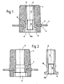
- a rubber buffer according to the invention is shown in a first embodiment as a central longitudinal section in FIG. 1, the two parts of the rubber buffer according to the invention according to FIG. 1 are shown as central longitudinal sections in FIG. 2, namely the rubber spring element and the threaded bushing.
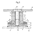
- 3 shows a further embodiment of the rubber buffer according to the invention in the installed state and thus the device according to the invention is again shown as a central longitudinal section.
- the rubber spring element 1 consists of an elastic material, in particular rubber, which is why rubber is used in connection with the invention when an elastic material is meant, that is to say, for example, an elastomer can replace the actual rubber.
- the rubber spring element is cylindrical and preferably tapered slightly tapering towards the upper end in the drawing. Near the other, lower in the drawing and consequently the end with the somewhat larger diameter, an annular groove is provided in the rubber spring element 1, the edges of which are slightly turned outward in a lip shape. An annular flange 2 is fixed in this annular groove, which is consequently superimposed by the upper annular groove lip 3 and is underlaid by the lower annular groove lip 4.
- the ring flange 2 consists of metal or a plastic with corresponding properties.
- a likewise essentially cylindrical longitudinal hole 5 is provided concentrically around the longitudinal axis of the rubber spring element 1. This longitudinal hole ends in the solution according to Fig.
- the extension is preferably a polygon, preferably a square.
- the diameter of the basic contour of the extension 6, in the case of a polygon, the diameter of the largest crisis corresponds at least approximately to the inside diameter of the first-mentioned ring flange 2, the outside diameter of which is significantly larger than the (largest) outside diameter of the rubber spring element 1.
- the ring groove for receiving the first-mentioned ring flange 2 lies between the inner surface of the extension 6 or the opening of the hole 5 into the extension 6 and a second ring groove 7. While the ring groove for the ring flange 2 has a rectangular cross-section around the ring flange without play and even with a predetermined bias, the second annular groove 7 has an arcuate cross section.
- a sleeve 8 is rotatably inserted, the upper portion 11 has a slightly larger inner diameter than the lower portion 12, which is provided with a screw thread 12a.
- the sleeve 8 has a radial flange 9 at the lower end to prevent rotation and to bear against the underside of the sleeve 8, whose outer contour and diameter corresponds to the outer contour and the diameter of the extension 6.
- the sleeve 8 is provided with an annular bead 10 with a spherical cross section, which is assigned to the flange 9 in the manner in which the annular groove 7 is associated with the extension 6 and whose cross section corresponds approximately to the cross section of the annular groove 7.
- the rubber spring element 1 is expanded to such an extent that the sleeve 8 can be inserted and is held in the rubber spring element 1 with a press fit after the expansion has ended (FIG. 1).
- the annular bead 10 lies in the annular groove 7, the radial flange 9 lies in the extension 6 in such a way that its inner end surface rests on the inner surface of the extension 6.
- the annular flange 2 and the radial flange 9 do not overlap in the radial direction, or at least to a small extent.
- the radial flange 9 has a significantly larger diameter than in the embodiment according to FIG.
- the rubber spring element 1 has no extension 6 of the longitudinal hole 5, and the radial flange 9 rests on the entire lower end face of the rubber spring element 1 and projects with a circular edge beyond the likewise circular end face of the rubber spring element 1.
- a plate-shaped first component 14 of relatively low mass is to be fixed in relation to any second component 13 of relatively large mass, for example the second component 13 is intended to be part of a vehicle bodywork which is to be made bullet-proof with an armor plate as a plate-shaped first component 14.
- An appropriate plurality of devices according to the invention are used for the determination, only one of which is shown and described in the installed state.
- the component 13 has a hole 15 and a ring 16 of a predetermined height is welded onto the component 14 on the side facing the component 13. Hole 13 and ring 16 are assigned to each other with the same axis.
- the device according to the invention with the flange 9 and the lower end of the rubber spring element 1 is inserted so far that the ring flange 2 on the upper edge of the ring 13 lie and is fixed in this position relative to the component 14 by ring flange 2 and ring 16, for example, permanently glued to one another or releasably connected to one another, for example by ring 16 at the upper end facing inwards and ring flange 2 having corresponding recesses, so that when inserted the cams can pass axially through the recesses and after rotation of the device according to the invention about its longitudinal axis the cams of the ring 16 lie over the non-recessed sections of the ring flange 2 and
- an annular disc 19 is placed on the top of the rubber spring element 1, but this may also have been previously placed on the rubber spring element and connected to it, for example glued.
- the outer diameter of the disk 19 is significantly larger than the diameter of the hole 15 of the component 13, while the inner diameter of the annular disk 18 corresponds approximately to the diameter of the section 11 of the longitudinal hole 5 of the sleeve 8.
- the screw 20 is inserted into the longitudinal hole 5 and screwed into its threaded section 12 until the head of the screw 20 is in the hole 15 has largely disappeared, with the interposition of a spring washer 21 resting on the annular disk 19 and by determining the distance between the radial flange 9 and the annular flange 2 or the first component 14 relative to the second component 13, the position of the lighter component 14 relative to the heavier component 13 is determined is and determines the bias in the rubber spring element 1.
- the outer diameter of the rubber spring element 1 in the area between the ring flange 2 and the end face of the spring element 1 or radial flange 9 closer to it is larger than the outer diameter of the rubber spring element 1 in the area between the ring flange 2 and the other end face of the rubber spring element 1.
- the component 14 is adjustable relative to the component 13 from a defined position. Since there is no metallic connection to each other, the two parts are vibration and temperature insulated from each other. Energy that strikes the component 14 vertically is absorbed in the rubber spring element 1 up to a relatively high value and is not passed on to the component 14.
- the component 14 can be fixed on the component 13 after appropriate preparation of the component 14 solely from the outside A of the component 13, the component 14 does not have to be interrupted in the area of the fastening be so that the connection is particularly suitable for releasably assigning an armor plate 14 to a vehicle structure 13.
- the device can absorb shear forces without the risk of damaging it. In the event of a fire, the rubber spring element 1 may burn, but the attachment of the component 14 to the component 13 would also be retained in principle.
Abstract
Description
Aufgabe der Erfindung ist es, einen Gummipuffer aufzuzeigen, der in besonders zweckmäßiger Weise dazu verwendet werden kann, schwingend zu lagernde Teile aufzunehmen oder als Abstandshalter zwischen gegeinander bewegliche Flächen eingebaut zu werden. Aufgabe der Erfindung ist es vor allem, eine für diesen Zweck geeignete Einrichtung zu schaffen. Schließlich zeigt die Erfindung eine besonders zweckmäßige Anwendungsmöglichkeit auf.The object of the invention is to show a rubber buffer which can be used in a particularly expedient manner to accommodate parts which are to be mounted in a vibrating manner or to be installed as spacers between surfaces which can be moved against one another. The primary object of the invention is to provide a device suitable for this purpose. Finally, the invention shows a particularly useful application.
Die Merkmale der Erfindung ergeben sich aus dem Kennzeichnungsteil des Anspruches 1 und den Unteransprüchen.The features of the invention result from the characterizing part of claim 1 and the subclaims.
Die Erfindung wird nachfolgend anhand der Zeichnung beschrieben. In der Zeichung ist in Fig. 1 ein erfindungsgemäßer Gummipuffer in einer ersten Ausführungsform als Mittellängsschnitt dargestellt, in Fig.2 sind die beiden Teile des erfindungsgemäßen Gummipuffers gemäß Fig.1 als Mittellängsschnitte dargestellt, nämlich das Gummifederelement und die Gewindebuchse. In Fig.3 ist eine weitere Ausführungsform des erfindungsgemäßen Gummipuffers im eingebauten Zustand und damit die erfindungsgemäße Einrichtung wiederum als Mittellängsschnitt dargestellt. Das Gummifederelement 1 besteht aus einem elastischen Material, insbesondere Gummi- weshalb im Zusammenhang mit der Erfindung von Gummi gesprochen wird, wenn ein elastisches Material gemeint ist, also beispielsweise auch ein Elastomer an die Stelle von eigentlichem Gummi treten kann.The invention is described below with reference to the drawing. In the drawing, a rubber buffer according to the invention is shown in a first embodiment as a central longitudinal section in FIG. 1, the two parts of the rubber buffer according to the invention according to FIG. 1 are shown as central longitudinal sections in FIG. 2, namely the rubber spring element and the threaded bushing. 3 shows a further embodiment of the rubber buffer according to the invention in the installed state and thus the device according to the invention is again shown as a central longitudinal section. The rubber spring element 1 consists of an elastic material, in particular rubber, which is why rubber is used in connection with the invention when an elastic material is meant, that is to say, for example, an elastomer can replace the actual rubber.
Das Gummifederelement ist zylindrisch und vorzugsweise schwach kegelig nach dem in der Zeichnung oberen Ende hin sich verjüngend ausgebildet. Nahe dem anderen, in der Zeichnung unteren und demzufolge Ende mit dem etwas größeren Durchmesser ist in dem Gummifederelement 1 eine Ringnut vorgesehen, deren Ränder etwas nach außen lippenförmig aufgestülpt sind. In dieser Ringnut ist ein Ringflansch 2 festgelegt, der demzufolge von der oberen Ringnutlippe 3 überlagert und von der unteren Ringnutlippe 4 unterlegt wird. Der Ringflansch 2 besteht aus Metall oder einem Kunststoff mit entsprechenden Eigenschaften. Konzentrisch um die Längsachse des Gummifederelementes 1 ist ein ebenfalls im wesentlichen zylinderischen Längsloch 5 vorgesehen. Dieses Längsloch endet bei der Lösung nach Fig.1,2 am in der Zeichnung unteren Ende in einer Erweiterung 6, die nach diesem Ende des Gummifederelementes hin ohne nochmalige Verengung, d.h. mit gleichbleibendem Durchmesser offen ist. Während das Loch 5 rund ist, ist die Erweiterung vorzugsweise ein Viel- vorzugsweise Vierkant. Der Durchmesser der Grundkontur der Erweiterung 6, bei einem Vielkant der Durchmesser des Größtkrises entspricht zumindest etwa dem Innendurchmesser des erstgenannten Ringflansches 2, dessen Außendurchmesser deutlich größer als der (größte) Außendurchmesser der Gummifederelementes 1 ist.The rubber spring element is cylindrical and preferably tapered slightly tapering towards the upper end in the drawing. Near the other, lower in the drawing and consequently the end with the somewhat larger diameter, an annular groove is provided in the rubber spring element 1, the edges of which are slightly turned outward in a lip shape. An
Die Ringnut zur Aufnahme des erstgenannten Ringflansches 2 liegt zwischen der Innenfläche der Erweiterung 6 bzw. der Einmündung des Loches 5 in die Erweiterung 6 und einer zweiten Ringnut 7. Während die Ringnut für den Ringflansch 2 rechteckigen Querschnitt hat, um den Ringflansch spiellos und sogar mit einer vorgegebenen Vorspannung aufzunehmen, hat die zweite Ringnut 7 einen bogenförmigen Querschnitt.The ring groove for receiving the first-mentioned
In das Längsloch 5 ist eine Hülse 8 drehfest eingesetzt, deren oberer Abschnitt 11 einen etwas größeren Innendurchmesser hat als der untere Abschnitt 12, der mit einem Schraubgewinde 12a versehen ist. Die Hülse 8 hat am unteren Ende als Verdrehsicherung und zur Anlage an der Unterseite der Hülse 8 einen Radialflansch 9, dessen Außenkontur und Durchmesser der Außenkontur und dem Durchmesser der Erweiterung 6 entspricht. Außerdem ist die Hülse 8 mit einem im Querschnitt balligen Ringwulst 10 versehen, der dem Flansch 9 in der Weise zugeordnet ist, wie die Ringnut 7 der Erweiterung 6 zugeordnet ist und dessen Querschnitt in etwa dem Querschnitt der Ringnut 7 entspricht.In the
Zum Zusammenbau der beiden Teile des Puffers wird das Gummifederelement 1 soweit aufgeweitet, daß die Hülse 8 eingeführt werden kann und nach Beendigung der Aufweitung mit Preßsitz in dem Gummifederelement 1 gehalten ist (Fig.1). Der Ringwulst 10 liegt in der Ringnut 7, der Radialflansch 9 liegt in der Erweiterung 6 derart, daß seine innere Endfläche an der Innenfläche der Erweiterung 6 anliegt.To assemble the two parts of the buffer, the rubber spring element 1 is expanded to such an extent that the sleeve 8 can be inserted and is held in the rubber spring element 1 with a press fit after the expansion has ended (FIG. 1). The
Bei dieser Ausführungsform des erfindungsgemäßen Gummipuffers überdecken sich Ringflansch 2 und Radialflansch 9 in radialer Richtung nicht oder allenfalls in geringem Maße.In this embodiment of the rubber buffer according to the invention, the
Bei der zweiten Ausführungsform (Fig.3) des erfindungsgemäßen Gummipuffers hat der Radialflansch 9 einen deutlich größeren Durchmeser als bei der Ausführungsform gemäß Fig.1,2. Außerdem weist das Gummifederelement 1 keine Erweiterung 6 des Längsloches 5 auf, und der Radialflansch 9 liegt auf der gesamten unteren Stirnseite des Gummifederelementes 1 auf und ragt mit einem kreisförmigen Rand über die ebenfalls kreisförmige Stirnfläche des Gummifederelementes 1 hinaus.In the second embodiment (FIG. 3) of the rubber buffer according to the invention, the
Der Einbau des erfindungsgemäßen Gummipuffers als Teil einer erfindungsgemäßen Einrichtung wird nachfolgend anhand der Ausführungsform gemäß Fig.3 beschrieben.The installation of the rubber buffer according to the invention as part of a device according to the invention is described below with reference to the embodiment according to FIG. 3.
Ein plattenförmiges erstes Bauteil 14 relativ geringer Masse soll gegenüber einem beliebigen zweiten Bauteil 13 relativ großer Masse festgelegt werden, wobei es sich beispielsweise bei dem zweiten Bauteil 13 um einen Teil einer Fahrzeugkarrosserie handeln soll, die mit einer Panzerplatte als plattenförmigem, ersten Bauteil 14 beschußsicher gemacht sein soll. Für die Festlegung dient eine angemessene Mehrzahl von erfindungsgemäßen Einrichtungen, von denen jedoch nur eine im Einbauzustand dargestellt und beschrieben ist.A plate-shaped
Im Bereich des Einbaues der Einrichtung weist das Bauteil 13 ein Loch 15 auf und ist auf der dem Bauteil 13 zugekehrten Seite auf dem Bauteil 14 ein Ring 16 vorgegebener Höhe angeschweißt. Loch 13 und Ring 16 sind achsgleich einander zugeordnet. In den von dem Ring 16 umschlossenen Freiraum wird, noch ehe das Bauteil 14 dem Bauteil 13 zugeordnet ist, die erfindungsgemäße Einrichtung mit dem Flansch 9 und dem unteren Ende des Gummifederelementes 1 soweit eingeführt, daß der Ringflansch 2 auf dem oberen Rand des Ringes 13 zu liegen kommt und in dieser Lage relativ zum Bauteil 14 festgelegt wird, indem Ringflansch 2 und Ring 16 beispielsweise miteinander dauerhaft verklebt werden oder lösbar miteinander verbunden werden, indem beispielsweise der Ring 16 am oberen Ende nach innen gerichtete Nocken und der Ringflansch 2 entsprechende Aussparungen aufweisen, so daß beim Einsetzen die Nocken durch die Aussparungen axial hindurchtreten können und nach einer Drehung der erfindungsgemäßen Vorrichtung um ihre Längsachse die Nocken des Ringes 16 über den nicht ausgesparten Abschnitten des Ringflansches 2 liegen und beide Teile in dieser Position mit Schrauben 17 miteinander verbunden werden können, oder indem die Wandstärke des Ringes 16 so bemessen ist, daß er Gewindelöcher aufweisen kann, in die die Schrauben 17 eingeschraubt werden, während sie mit ihren Köpfen über Durchgangslöchern in dem Ringflansch 2 auf dessen Oberseite aufliegen. Im Fall der einen oder anderen lösbaren Verbindung ist zwischen der Oberseite des Ringflansches 2 und den Unterseiten der Schraubenköpfe 17 eine Unterlegscheibe 18 eingelegt.In the area where the device is installed, the
Ist auf diese Weise die Einrichtung aus dem Gummifederelement 1, der Hülse 8 und dem Ringflansch 2 dem Bauteil 14 in einer der beschriebenen oder einer anderen Weise lösbar oder nicht lösbar zugeordnet, so wird auf die Oberseite des Gummifederelementes 1 eine Ringscheibe 19 aufgelegt, die aber auch bereits vorher auf das Gummifederelement aufgelegt und mit dieser verbunden, beispielsweise verklebt worden sein kann. Der Außendurchmesser der Scheibe 19 ist deutlich größer als der Durchmesser des Loches 15 des Bauteiles 13, während der Innendurchmesser der Ringscheibe 18 etwa dem Durchmesser des Abschnittes 11 des Längsloches 5 der Hülse 8 entspricht. Ist die insoweit vorbereitete erfindungsgemäße Einrichtung mit dem ersten Bauteil 14 über die Scheibe 19 an das zweite Bauteil 13 angelegt, so wird die Schraube 20 in das Längsloch 5 eingeführt und in dessen Gewindeabschnitt 12 solange eingeschraubt, bis der Kopf der Schraube 20 in dem Loch 15 weitestgehend verschwunden ist, unter Zwischenschaltung einer Federscheibe 21 auf der Ringscheibe 19 aufliegt und durch Festlegung des Abstandes zwischen dem Radialflansch 9 und dem Ringflansch 2 bzw. des ersten Bauteiles 14 gegenüber dem zweiten Bauteil 13 die Lage des leichteren Bauteiles 14 gegenüber dem schwereren Bauteil 13 festgelegt ist und die Vorspannung in dem Gummifederelement 1 bestimmt. Zumindest durch die aufgebrachte axiale Vorspannung ist der Außendurchmesser des Gummifederelementes 1 im Bereich zwischen Ringflansch 2 und ihm näherer Stirnseite des Federelementes 1 bzw. Radialflansch 9 größer als der Außendurchmesser des Gummifederelementes 1 im Bereich zwischen dem Ringflansch 2 und der anderen Stirnseite des Gummifederelementes 1. Soweit es die Vorspannung zuläßt, ist das Bauteil 14 relativ zum Bauteil 13 aus einer definierten Lage heraus verstellbar. Da keine metallische Verbindung zueinander besteht, sind die beiden Teile gegeneinander schwingungs- und temperatur-isoliert. Auf das Bauteil 14 senkrecht auftreffende Energie wird in dem Gummifederelement 1 bis zu einem relativ hohen Wert aufgenommen und nicht in das Bauteil 14 weitergeleitet. Die Festlegung des Bauteiles 14 am Bauteil 13 kann nach entsprechender Vorbereitung des Bauteiles 14 allein von der Außenseite A des Bauteiles 13 aus erfolgen, das Bauteil 14 muß im Bereich der Befestigung nicht unterbrochen sein, so daß die Verbindung in besonderem Maße dafür geeignet ist, eine Panzerplatte 14 lösbar einer Fahrzeugstruktur 13 zuzuordnen. Die Einrichtung kann Scherkräfte aufnehmen, ohne daß die Gefahr besteht, daß sie beschädigt wird. Im Fall eines Brandes kann zwar das Gummifederelement 1 verbrennen die Befestigung des Bauteiles 14 an dem Bauteil 13 würde aber auch dann grundsätzlich erhalten bleiben.In this way, the device from the rubber spring element 1, the sleeve 8 and the
Claims (20)
daß das Gummifederelement (1) zumindest etwa zylindrische Form hat und eine in seiner Längsrichtung verlaufende, durchgehende, zylindrische Öffnung (5) aufweist, daß in dieser Öffnung die Gewindehülse (8) fest angeordnet ist, die mit einem Radialflansch (9) an ihrem einen Ende an der zugehörigen, dem ersten Bauteil (14) zugewandten Stirnseite des Gummifederelementes anliegt, daß nahe diesem Ende in dem Gummifederelement ein Ringflansch (2) gehalten ist, der mit dem ersten Bauteil (14) fest oder lösbar verbunden ist, wobei zwischen dem Radialflansch und dem ersten Bauteil ein Abstand in Längsrichtung des Gummifederelementes besteht und daß in den Gewindeabschnitt (12) der Gewindehülse von der anderen, dem zweiten Bauteil (13) zugewandten Stirnseite des Gummifederelementes her eine Schraube (20) eingeschraubt ist, die durch eine Öffnung (15) im zweiten Bauteil (13) hindurchgeführt ist und über den Ringflansch das Gummifederelement mit der anderen Stirnseite an der Innenseite des zweiten Bauteils unter axialer Vorspannung anlegt.1. Device for the elastic connection of a flat, first component of low mass with a second, any component of relatively large mass using a rubber spring element which is detachably connected to the second component, fixed or detachably connected to the first component, the connection with the aid of a Screw that can be screwed into a threaded sleeve received by the rubber spring element, characterized in that
that the rubber spring element (1) has at least approximately cylindrical shape and has a continuous cylindrical opening (5) running in its longitudinal direction, that in this opening the threaded sleeve (8) is fixedly arranged, which has a radial flange (9) on one End rests on the associated end face of the rubber spring element facing the first component (14), that an annular flange (2) is held near this end in the rubber spring element, which ring is fixed or detachably connected to the first component (14), between the radial flange and there is a distance in the longitudinal direction of the rubber spring element from the first component and that a screw (20) is screwed into the threaded section (12) of the threaded sleeve from the other end face of the rubber spring element facing the second component (13), said screw being screwed through an opening (15 ) is passed through in the second component (13) and, via the ring flange, rests the rubber spring element with the other end face on the inside of the second component under axial prestress.
dadurch gekennzeichnet,
daß die Schraube (20) mit Ihrem Kopf in der Öffnung (15) des zweiten Bauteiles (13) liegt und das Gummifederelement (1) über eine Scheibe (19) an die Innenseite des zweiten Bauteiles (13) anlegt.2. Device according to claim 1,
characterized,
that the screw (20) lies with its head in the opening (15) of the second component (13) and the rubber spring element (1) abuts the inside of the second component (13) via a washer (19).
gekennzeichnet durch einen axialen Abstand zwischen der Gewindehülse (8) und der Scheibe (19).3. Device according to claims 1 and 2,
characterized by an axial distance between the threaded sleeve (8) and the washer (19).
dadurch gekennzeichnet,
daß der Ringflansch (2) lösbar mit einem Ring (16) verbunden ist, der dem ersten Bauteil (14) zugeordnet ist und den unterhalb des Ringflansches (2) liegenden Teil des Gummifederelementes (1) mit dem Radialflansch (9) umschließt.4. Device according to one of claims 1-3,
characterized,
that the ring flange (2) is detachably connected to a ring (16) which is assigned to the first component (14) and which surrounds the part of the rubber spring element (1) lying below the ring flange (2) with the radial flange (9).
dadurch gekennzeichnet,
daß das zylindrische Gummifederelement (1) und die zylindrische Gewindehülse (8) achsgleich angeordnet und verdrehfest miteinander verbunden sind und daß das Gummifederelement einen Ringflansch (2) aufnimmt, dessen Innendurchmesser größer als der Außendurchmesser der Gewindehülse und kleiner als der Außendurchmesser des Gummifederelementes ist, während sein Außendurchmesser größer als der Außendurchmesser des Gummifederelementes ist.5. rubber buffer with a threaded sleeve inserted into a rubber spring element, in particular for use in a device according to at least one of claims 1 to 4,
characterized,
that the cylindrical rubber spring element (1) and the cylindrical threaded sleeve (8) are arranged coaxially and non-rotatably connected to each other and that the rubber spring element receives an annular flange (2), the inner diameter of which is larger than the outer diameter of the threaded sleeve and smaller than the outer diameter of the rubber spring element, while its outer diameter is larger than the outer diameter of the rubber spring element.
dadurch gekennzeichnet,
daß der Ringflansch (2) aus Metall oder einem entsprechend starren bzw. entsprechend begrenzt verformbaren Kunststoff besteht.6. rubber buffer according to claim 5,
characterized,
that the ring flange (2) consists of metal or a correspondingly rigid or correspondingly deformable plastic.
dadurch gekennzeichnet,
daß Gummifederelement (1) den Ringflansch (2) auf dessen Ober- und Unterseite mit je einer lippenförmigen, ringförmigen Ausstülpung (3,4) überlagert bzw. unterlegt.7. rubber buffer according to claim 5 or 6,
characterized,
that rubber spring element (1) overlaps or underlays the annular flange (2) on the top and bottom thereof with a lip-shaped, annular protuberance (3, 4).
dadurch gekennzeichnet,
daß der Abstand des Ringflansches (2) vom einen Ende des Gummifederelementes (1) deutlich kleiner ist als vom anderen Ende des Gummifederelementes.8. rubber buffer according to one of claims 5 to 7,
characterized,
that the distance of the ring flange (2) from one end of the rubber spring element (1) is significantly smaller than from the other end of the rubber spring element.
dadurch gekennzeichnet,
daß die Gewindehülse (8) am einen Ende einen nach außen gerichteten Radialflansch (9) aufweist, der am entsprechenden einen Ende des Gummifederelementes (1) anliegt.9. rubber buffer according to one of claims 5 to 8,
characterized,
that the threaded sleeve (8) has at one end an outwardly directed radial flange (9) which abuts the corresponding one end of the rubber spring element (1).
dadurch gekennzeichnet,
daß die Gewindehülse (8) mit dem Radialflansch (2) in einer Erweiterung (6) des Aufnahmeloches (5) des Gummifederelementes (1) liegt.10. rubber buffer according to claim 9,
characterized,
that the threaded sleeve (8) with the radial flange (2) lies in an extension (6) of the receiving hole (5) of the rubber spring element (1).
dadurch gekennzeichnet,
daß die Stirnseite des Gummifederelementes (1), an der die Gewindehülse (8) mit ihrem Radialflansch (9) anliegt, die Stirnseite des Gummifederelementes ist, dem der Ringflansch (2) näher ist.11. Rubber buffer according to one of claims 9 to 10,
characterized,
that the end face of the rubber spring element (1) against which the threaded sleeve (8) rests with its radial flange (9) is the end face of the rubber spring element to which the ring flange (2) is closer.
dadurch gekennzeichnet,
daß das Aufnahmeloch (5) des Gummifederelementes (1) für die Längsbohrung (11,12) der Gewindehülse (8) nach beiden Enden des Gummifederelementes hin offen ist.12. rubber buffer according to one of claims 5 to 11,
characterized,
that the receiving hole (5) of the rubber spring element (1) for the longitudinal bore (11, 12) of the threaded sleeve (8) is open towards both ends of the rubber spring element.
dadurch gekennzeichnet,
daß der Radialflansch (9) der Gewindebuchse (8) zwischen dem erstgenannten Ringflansch (8) und dem Ende des Gummifederelementes (1) liegt, dem der erstgenannte Ringflansch näher liegt.13. rubber buffer according to one of claims 5 to 12,
characterized,
that the radial flange (9) of the threaded bushing (8) lies between the first-mentioned ring flange (8) and the end of the rubber spring element (1), which is closer to the first-mentioned ring flange.
dadurch gekennzeichnet,
daß der Außendurchmesser des Radialflansches (9) dem Durchmesser der Erweiterung (6) des Aufnahmeloches (5) und zumindest etwa dem Innendurchmesser des erstgenannten Ringflansches (2) entspricht.14. rubber buffer according to claims 5 and 9 to 11,
characterized,
that the outer diameter of the radial flange (9) corresponds to the diameter of the enlargement (6) of the receiving hole (5) and at least approximately the inner diameter of the first-mentioned ring flange (2).
dadurch gekennzeichnet,
daß der Durchmesser des Gummifederelementes im Bereich zwischen dem Ringflansch (2) und dem näheren Ende des Gummifederelementes größer ist, als der Durchmesser des Gummifederelementes im Bereich zwischen dem Ringflansch und dem entfernteren Ende des Gummifederelementes und der Außendurchmesser des Radialflansches (9) deutlich größer ist als der größere Außendurchmesser des Gummifederelementes.15. rubber buffer according to claims 5 and 9,
characterized,
that the diameter of the rubber spring element in the area between the ring flange (2) and the nearer end of the rubber spring element is larger than the diameter of the rubber spring element in the area between the ring flange and the more distant end of the rubber spring element and the outer diameter of the radial flange (9) is significantly larger than the larger outside diameter of the rubber spring element.
dadurch gekennzeichnet,
daß der erstgenannte Ringflansch (2) zwischen dem Radialflansch (9) der Gewindehülse (8) und einem Ringwulst (10) der Gewindehülse liegt, wobei der Ringwulst von einer entsprechenden Ringnut (7) des Gummifederelementes (1) aufgenommen ist.16. rubber buffer according to claim 5 and at least one of claims 8 to 14,
characterized,
that the first-mentioned ring flange (2) between the radial flange (9) of the threaded sleeve (8) and an annular bead (10) Threaded sleeve is located, the annular bead being received by a corresponding annular groove (7) of the rubber spring element (1).
dadurch gekennzeichnet,
daß der Radialflansch (9) der Gewindehülse (8) und die Erweiterung (6) des Aufnahmeloches (5) des Gummifederelementes (1) gleich dimensionierte Vielecke sind.17. A rubber buffer according to claims 1 and 10 and at least one of claims 7 to 12 in relation to claim 6,
characterized,
that the radial flange (9) of the threaded sleeve (8) and the extension (6) of the receiving hole (5) of the rubber spring element (1) are polygons of the same dimensions.
dadurch gekennzeichnet,
daß die Gewindehülse (8) mit Preßsitz in dem Aufnahmeloch (5) des Gummifederelementes (1) sitzt.18. Rubber buffer according to one of claims 1 to 17,
characterized,
that the threaded sleeve (8) sits with a press fit in the receiving hole (5) of the rubber spring element (1).
dadurch gekennzeichnet,
daß die Längsbohrung der Gewindehülse (8) zwei Abschnitte (11,12) mit unterschiedlichen Durchmessern hat, von denen der Abschnitt mit dem kleineren Durchmesser (12) dem Ende des Gummifederelementes (1) zugeordnet ist, dem der erste Ringflansch (2) und der Radialflansch (9) der Gewindebuchse (8) näher liegen und dieser Abschnitt mit einem Schraubgewinde versehen ist.19. Rubber buffer according to one of claims 1 to 18,
characterized,
that the longitudinal bore of the threaded sleeve (8) has two sections (11, 12) with different diameters, of which the section with the smaller diameter (12) is assigned to the end of the rubber spring element (1) to which the first ring flange (2) and Radial flange (9) of the threaded bushing (8) are closer and this section is provided with a screw thread.
Applications Claiming Priority (2)
| Application Number | Priority Date | Filing Date | Title |
|---|---|---|---|
| DE8707802U | 1987-06-01 | ||
| DE8707802U DE8707802U1 (en) | 1987-06-01 | 1987-06-01 |
Publications (3)
| Publication Number | Publication Date |
|---|---|
| EP0293631A2 true EP0293631A2 (en) | 1988-12-07 |
| EP0293631A3 EP0293631A3 (en) | 1990-05-02 |
| EP0293631B1 EP0293631B1 (en) | 1993-11-10 |
Family
ID=6808709
Family Applications (1)
| Application Number | Title | Priority Date | Filing Date |
|---|---|---|---|
| EP88107316A Expired - Lifetime EP0293631B1 (en) | 1987-06-01 | 1988-05-06 | Device for connecting a first constructional part of relatively low mass to a second constructional part of relatively heavy mass and application of such a device |
Country Status (2)
| Country | Link |
|---|---|
| EP (1) | EP0293631B1 (en) |
| DE (2) | DE8707802U1 (en) |
Cited By (2)
| Publication number | Priority date | Publication date | Assignee | Title |
|---|---|---|---|---|
| EP0874175A2 (en) * | 1997-04-25 | 1998-10-28 | Alps Electric Co., Ltd. | Anti-vibration mechanism and disk drive device using the same |
| WO2002006696A1 (en) * | 2000-07-14 | 2002-01-24 | Basf Aktiengesellschaft | Spring element |
Citations (8)
| Publication number | Priority date | Publication date | Assignee | Title |
|---|---|---|---|---|
| GB482260A (en) * | 1936-03-05 | 1938-03-21 | Hugh Compton Lord | Cushion joints or mountings |
| FR951846A (en) * | 1946-08-28 | 1949-11-04 | Ford | Elastic mounting |
| US2830780A (en) * | 1953-06-30 | 1958-04-15 | Schloss Fred | Low frequency noise and shock isolation mount |
| FR1260978A (en) * | 1960-06-18 | 1961-05-12 | Goodrich Co B F | Elastic support |
| US3809427A (en) * | 1972-10-03 | 1974-05-07 | Bennett Equipment Corp | Vehicle body mount |
| DE2310560A1 (en) * | 1973-03-02 | 1974-09-05 | Continental Gummi Werke Ag | MEMBRANE SHAPED SPRING ELEMENT |
| US3881767A (en) * | 1973-09-12 | 1975-05-06 | Gen Motors Corp | Vehicle impact energy absorption and suspension system |
| JPS5586936A (en) * | 1979-11-14 | 1980-07-01 | Showa Electric Wire & Cable Co Ltd | Manufacturing method of multistage anti-vibration rubber |
-
1987
- 1987-06-01 DE DE8707802U patent/DE8707802U1/de not_active Expired
-
1988
- 1988-05-06 DE DE88107316T patent/DE3885510D1/en not_active Expired - Fee Related
- 1988-05-06 EP EP88107316A patent/EP0293631B1/en not_active Expired - Lifetime
Patent Citations (8)
| Publication number | Priority date | Publication date | Assignee | Title |
|---|---|---|---|---|
| GB482260A (en) * | 1936-03-05 | 1938-03-21 | Hugh Compton Lord | Cushion joints or mountings |
| FR951846A (en) * | 1946-08-28 | 1949-11-04 | Ford | Elastic mounting |
| US2830780A (en) * | 1953-06-30 | 1958-04-15 | Schloss Fred | Low frequency noise and shock isolation mount |
| FR1260978A (en) * | 1960-06-18 | 1961-05-12 | Goodrich Co B F | Elastic support |
| US3809427A (en) * | 1972-10-03 | 1974-05-07 | Bennett Equipment Corp | Vehicle body mount |
| DE2310560A1 (en) * | 1973-03-02 | 1974-09-05 | Continental Gummi Werke Ag | MEMBRANE SHAPED SPRING ELEMENT |
| US3881767A (en) * | 1973-09-12 | 1975-05-06 | Gen Motors Corp | Vehicle impact energy absorption and suspension system |
| JPS5586936A (en) * | 1979-11-14 | 1980-07-01 | Showa Electric Wire & Cable Co Ltd | Manufacturing method of multistage anti-vibration rubber |
Non-Patent Citations (1)
| Title |
|---|
| PATENT ABSTRACTS OF JAPAN, Band 4, Nr. 128 (M-31)[610], 9. September 1980; & JP-A-55 86 936 (SHOWA DENSEN DENRAN K.K.) 01-07-1980 * |
Cited By (5)
| Publication number | Priority date | Publication date | Assignee | Title |
|---|---|---|---|---|
| EP0874175A2 (en) * | 1997-04-25 | 1998-10-28 | Alps Electric Co., Ltd. | Anti-vibration mechanism and disk drive device using the same |
| EP0874175A3 (en) * | 1997-04-25 | 2000-04-12 | Alps Electric Co., Ltd. | Anti-vibration mechanism and disk drive device using the same |
| CN1111864C (en) * | 1997-04-25 | 2003-06-18 | 阿尔卑斯电气株式会社 | Vibration proof mechanism and adopt the disk drive device of this vibration proof mechanism |
| WO2002006696A1 (en) * | 2000-07-14 | 2002-01-24 | Basf Aktiengesellschaft | Spring element |
| US6857626B2 (en) | 2000-07-14 | 2005-02-22 | Basf Aktiengesellschaft | Spring element |
Also Published As
| Publication number | Publication date |
|---|---|
| DE3885510D1 (en) | 1993-12-16 |
| EP0293631B1 (en) | 1993-11-10 |
| DE8707802U1 (en) | 1987-07-23 |
| EP0293631A3 (en) | 1990-05-02 |
Similar Documents
| Publication | Publication Date | Title |
|---|---|---|
| DE2718170C3 (en) | Fastening clips for covered cover plates, in particular for motor vehicles | |
| EP0543046B1 (en) | Screw unit | |
| EP0937311B1 (en) | Device for fixing a distance sensor to an automobile | |
| DE4406270C1 (en) | Spring washer for securing screws, nuts or the like | |
| EP1104852A1 (en) | Vibration damping device for detachably connecting two parts with a rotatable pin a retaining spring and a vibration dampening ring | |
| WO2000060207A1 (en) | Device for fixing a glass panel to a support at the side of a building | |
| DE2054998A1 (en) | Body frame connector for motor vehicles | |
| DE3132855A1 (en) | Rosette lower part | |
| EP3153725B1 (en) | Method and device for fixing a plastic component to a carrying component | |
| DE3739663A1 (en) | Adjustable shock-absorbing leg for motor vehicles | |
| DE3822322C2 (en) | Impact absorber with a predetermined breaking point | |
| DE3207922C1 (en) | Pivot mounting for a door-holding hinge of a door stop for motor-vehicle doors | |
| DE3138534C2 (en) | ||
| DE2109812C3 (en) | Holder for elastic fastening of facing panels to walls or floors in rooms | |
| EP0293631B1 (en) | Device for connecting a first constructional part of relatively low mass to a second constructional part of relatively heavy mass and application of such a device | |
| EP0047961B1 (en) | Ball-neck coupling for motor vehicles | |
| DE3811401C2 (en) | ||
| DE1683207B1 (en) | Fastening device for building cladding that can be changed at a distance | |
| DE69720665T2 (en) | Suspension device for a motor vehicle | |
| DE4136230C2 (en) | Bumper system for motor vehicles | |
| DE102012112362B3 (en) | Valve with a fastening device | |
| DE19647607C2 (en) | Device for fixing double-skin insulating glass panes on supporting structures | |
| DE4136598A1 (en) | Rubber metal buffer element for insulating attachments - allows screwless fixing of items using blind rivet and rivet hole | |
| EP1096156B1 (en) | Preassembled securing screw | |
| DE2946993C2 (en) |
Legal Events
| Date | Code | Title | Description |
|---|---|---|---|
| PUAI | Public reference made under article 153(3) epc to a published international application that has entered the european phase |
Free format text: ORIGINAL CODE: 0009012 |
|
| AK | Designated contracting states |
Kind code of ref document: A2 Designated state(s): CH DE FR GB LI |
|
| RIN1 | Information on inventor provided before grant (corrected) | ||
| PUAL | Search report despatched |
Free format text: ORIGINAL CODE: 0009013 |
|
| AK | Designated contracting states |
Kind code of ref document: A3 Designated state(s): CH DE FR GB LI |
|
| 17P | Request for examination filed |
Effective date: 19901025 |
|
| 17Q | First examination report despatched |
Effective date: 19920428 |
|
| GRAA | (expected) grant |
Free format text: ORIGINAL CODE: 0009210 |
|
| AK | Designated contracting states |
Kind code of ref document: B1 Designated state(s): CH DE FR GB LI |
|
| ET | Fr: translation filed | ||
| GBT | Gb: translation of ep patent filed (gb section 77(6)(a)/1977) |
Effective date: 19931111 |
|
| REF | Corresponds to: |
Ref document number: 3885510 Country of ref document: DE Date of ref document: 19931216 |
|
| PLBE | No opposition filed within time limit |
Free format text: ORIGINAL CODE: 0009261 |
|
| STAA | Information on the status of an ep patent application or granted ep patent |
Free format text: STATUS: NO OPPOSITION FILED WITHIN TIME LIMIT |
|
| 26N | No opposition filed | ||
| PGFP | Annual fee paid to national office [announced via postgrant information from national office to epo] |
Ref country code: GB Payment date: 20000508 Year of fee payment: 13 |
|
| PGFP | Annual fee paid to national office [announced via postgrant information from national office to epo] |
Ref country code: CH Payment date: 20000510 Year of fee payment: 13 |
|
| PGFP | Annual fee paid to national office [announced via postgrant information from national office to epo] |
Ref country code: FR Payment date: 20000530 Year of fee payment: 13 |
|
| PG25 | Lapsed in a contracting state [announced via postgrant information from national office to epo] |
Ref country code: GB Free format text: LAPSE BECAUSE OF NON-PAYMENT OF DUE FEES Effective date: 20010506 |
|
| PG25 | Lapsed in a contracting state [announced via postgrant information from national office to epo] |
Ref country code: LI Free format text: LAPSE BECAUSE OF NON-PAYMENT OF DUE FEES Effective date: 20010605 Ref country code: CH Free format text: LAPSE BECAUSE OF NON-PAYMENT OF DUE FEES Effective date: 20010605 |
|
| PGFP | Annual fee paid to national office [announced via postgrant information from national office to epo] |
Ref country code: DE Payment date: 20010608 Year of fee payment: 14 |
|
| GBPC | Gb: european patent ceased through non-payment of renewal fee |
Effective date: 20010506 |
|
| REG | Reference to a national code |
Ref country code: CH Ref legal event code: PL |
|
| PG25 | Lapsed in a contracting state [announced via postgrant information from national office to epo] |
Ref country code: FR Free format text: LAPSE BECAUSE OF NON-PAYMENT OF DUE FEES Effective date: 20020131 |
|
| PG25 | Lapsed in a contracting state [announced via postgrant information from national office to epo] |
Ref country code: DE Free format text: LAPSE BECAUSE OF NON-PAYMENT OF DUE FEES Effective date: 20021203 |