EP0293081A1 - Disposable peristaltic pump cassette system - Google Patents
Disposable peristaltic pump cassette system Download PDFInfo
- Publication number
- EP0293081A1 EP0293081A1 EP88303734A EP88303734A EP0293081A1 EP 0293081 A1 EP0293081 A1 EP 0293081A1 EP 88303734 A EP88303734 A EP 88303734A EP 88303734 A EP88303734 A EP 88303734A EP 0293081 A1 EP0293081 A1 EP 0293081A1
- Authority
- EP
- European Patent Office
- Prior art keywords
- cassette
- roller head
- irrigation
- aspiration system
- tubing
- Prior art date
- Legal status (The legal status is an assumption and is not a legal conclusion. Google has not performed a legal analysis and makes no representation as to the accuracy of the status listed.)
- Granted
Links
- 230000002572 peristaltic effect Effects 0.000 title claims description 23
- 238000001802 infusion Methods 0.000 claims abstract description 39
- 230000002262 irrigation Effects 0.000 claims abstract 26
- 238000003973 irrigation Methods 0.000 claims abstract 26
- 239000012530 fluid Substances 0.000 claims description 14
- 238000004891 communication Methods 0.000 claims description 8
- 238000005086 pumping Methods 0.000 claims description 8
- 230000001747 exhibiting effect Effects 0.000 claims 2
- 239000007788 liquid Substances 0.000 description 11
- 230000000994 depressogenic effect Effects 0.000 description 7
- 239000003978 infusion fluid Substances 0.000 description 6
- 230000000881 depressing effect Effects 0.000 description 4
- 238000000034 method Methods 0.000 description 4
- 239000000463 material Substances 0.000 description 3
- 238000001356 surgical procedure Methods 0.000 description 3
- 238000005520 cutting process Methods 0.000 description 2
- 238000002406 microsurgery Methods 0.000 description 2
- 239000002245 particle Substances 0.000 description 2
- 238000007789 sealing Methods 0.000 description 2
- 239000006260 foam Substances 0.000 description 1
- 230000036512 infertility Effects 0.000 description 1
- 238000004519 manufacturing process Methods 0.000 description 1
- 238000005259 measurement Methods 0.000 description 1
- 229920001296 polysiloxane Polymers 0.000 description 1
- 238000003825 pressing Methods 0.000 description 1
- 230000000284 resting effect Effects 0.000 description 1
- 230000000717 retained effect Effects 0.000 description 1
- 238000003860 storage Methods 0.000 description 1
- 230000007704 transition Effects 0.000 description 1
Images


Classifications
-
- F—MECHANICAL ENGINEERING; LIGHTING; HEATING; WEAPONS; BLASTING
- F04—POSITIVE - DISPLACEMENT MACHINES FOR LIQUIDS; PUMPS FOR LIQUIDS OR ELASTIC FLUIDS
- F04B—POSITIVE-DISPLACEMENT MACHINES FOR LIQUIDS; PUMPS
- F04B43/00—Machines, pumps, or pumping installations having flexible working members
- F04B43/12—Machines, pumps, or pumping installations having flexible working members having peristaltic action
- F04B43/1253—Machines, pumps, or pumping installations having flexible working members having peristaltic action by using two or more rollers as squeezing elements, the rollers moving on an arc of a circle during squeezing
-
- A—HUMAN NECESSITIES
- A61—MEDICAL OR VETERINARY SCIENCE; HYGIENE
- A61F—FILTERS IMPLANTABLE INTO BLOOD VESSELS; PROSTHESES; DEVICES PROVIDING PATENCY TO, OR PREVENTING COLLAPSING OF, TUBULAR STRUCTURES OF THE BODY, e.g. STENTS; ORTHOPAEDIC, NURSING OR CONTRACEPTIVE DEVICES; FOMENTATION; TREATMENT OR PROTECTION OF EYES OR EARS; BANDAGES, DRESSINGS OR ABSORBENT PADS; FIRST-AID KITS
- A61F9/00—Methods or devices for treatment of the eyes; Devices for putting-in contact lenses; Devices to correct squinting; Apparatus to guide the blind; Protective devices for the eyes, carried on the body or in the hand
- A61F9/007—Methods or devices for eye surgery
- A61F9/00709—Instruments for removing foreign bodies
-
- A—HUMAN NECESSITIES
- A61—MEDICAL OR VETERINARY SCIENCE; HYGIENE
- A61M—DEVICES FOR INTRODUCING MEDIA INTO, OR ONTO, THE BODY; DEVICES FOR TRANSDUCING BODY MEDIA OR FOR TAKING MEDIA FROM THE BODY; DEVICES FOR PRODUCING OR ENDING SLEEP OR STUPOR
- A61M1/00—Suction or pumping devices for medical purposes; Devices for carrying-off, for treatment of, or for carrying-over, body-liquids; Drainage systems
- A61M1/71—Suction drainage systems
- A61M1/72—Cassettes forming partially or totally the fluid circuit
-
- A—HUMAN NECESSITIES
- A61—MEDICAL OR VETERINARY SCIENCE; HYGIENE
- A61M—DEVICES FOR INTRODUCING MEDIA INTO, OR ONTO, THE BODY; DEVICES FOR TRANSDUCING BODY MEDIA OR FOR TAKING MEDIA FROM THE BODY; DEVICES FOR PRODUCING OR ENDING SLEEP OR STUPOR
- A61M1/00—Suction or pumping devices for medical purposes; Devices for carrying-off, for treatment of, or for carrying-over, body-liquids; Drainage systems
- A61M1/71—Suction drainage systems
- A61M1/77—Suction-irrigation systems
-
- A—HUMAN NECESSITIES
- A61—MEDICAL OR VETERINARY SCIENCE; HYGIENE
- A61M—DEVICES FOR INTRODUCING MEDIA INTO, OR ONTO, THE BODY; DEVICES FOR TRANSDUCING BODY MEDIA OR FOR TAKING MEDIA FROM THE BODY; DEVICES FOR PRODUCING OR ENDING SLEEP OR STUPOR
- A61M1/00—Suction or pumping devices for medical purposes; Devices for carrying-off, for treatment of, or for carrying-over, body-liquids; Drainage systems
- A61M1/80—Suction pumps
- A61M1/82—Membrane pumps, e.g. bulbs
-
- A—HUMAN NECESSITIES
- A61—MEDICAL OR VETERINARY SCIENCE; HYGIENE
- A61M—DEVICES FOR INTRODUCING MEDIA INTO, OR ONTO, THE BODY; DEVICES FOR TRANSDUCING BODY MEDIA OR FOR TAKING MEDIA FROM THE BODY; DEVICES FOR PRODUCING OR ENDING SLEEP OR STUPOR
- A61M3/00—Medical syringes, e.g. enemata; Irrigators
- A61M3/02—Enemata; Irrigators
- A61M3/0201—Cassettes therefor
-
- F—MECHANICAL ENGINEERING; LIGHTING; HEATING; WEAPONS; BLASTING
- F04—POSITIVE - DISPLACEMENT MACHINES FOR LIQUIDS; PUMPS FOR LIQUIDS OR ELASTIC FLUIDS
- F04B—POSITIVE-DISPLACEMENT MACHINES FOR LIQUIDS; PUMPS
- F04B43/00—Machines, pumps, or pumping installations having flexible working members
- F04B43/12—Machines, pumps, or pumping installations having flexible working members having peristaltic action
-
- A—HUMAN NECESSITIES
- A61—MEDICAL OR VETERINARY SCIENCE; HYGIENE
- A61M—DEVICES FOR INTRODUCING MEDIA INTO, OR ONTO, THE BODY; DEVICES FOR TRANSDUCING BODY MEDIA OR FOR TAKING MEDIA FROM THE BODY; DEVICES FOR PRODUCING OR ENDING SLEEP OR STUPOR
- A61M1/00—Suction or pumping devices for medical purposes; Devices for carrying-off, for treatment of, or for carrying-over, body-liquids; Drainage systems
- A61M1/71—Suction drainage systems
- A61M1/74—Suction control
- A61M1/741—Suction control with means for varying suction manually
- A61M1/7411—Suction control with means for varying suction manually by changing the size of a vent
-
- A—HUMAN NECESSITIES
- A61—MEDICAL OR VETERINARY SCIENCE; HYGIENE
- A61M—DEVICES FOR INTRODUCING MEDIA INTO, OR ONTO, THE BODY; DEVICES FOR TRANSDUCING BODY MEDIA OR FOR TAKING MEDIA FROM THE BODY; DEVICES FOR PRODUCING OR ENDING SLEEP OR STUPOR
- A61M2205/00—General characteristics of the apparatus
- A61M2205/12—General characteristics of the apparatus with interchangeable cassettes forming partially or totally the fluid circuit
-
- A—HUMAN NECESSITIES
- A61—MEDICAL OR VETERINARY SCIENCE; HYGIENE
- A61M—DEVICES FOR INTRODUCING MEDIA INTO, OR ONTO, THE BODY; DEVICES FOR TRANSDUCING BODY MEDIA OR FOR TAKING MEDIA FROM THE BODY; DEVICES FOR PRODUCING OR ENDING SLEEP OR STUPOR
- A61M2205/00—General characteristics of the apparatus
- A61M2205/27—General characteristics of the apparatus preventing use
- A61M2205/273—General characteristics of the apparatus preventing use preventing reuse, e.g. of disposables
-
- A—HUMAN NECESSITIES
- A61—MEDICAL OR VETERINARY SCIENCE; HYGIENE
- A61M—DEVICES FOR INTRODUCING MEDIA INTO, OR ONTO, THE BODY; DEVICES FOR TRANSDUCING BODY MEDIA OR FOR TAKING MEDIA FROM THE BODY; DEVICES FOR PRODUCING OR ENDING SLEEP OR STUPOR
- A61M2210/00—Anatomical parts of the body
- A61M2210/06—Head
- A61M2210/0612—Eyes
Definitions
- This invention relates to peristaltic pumps and, in particular, to peristaltic pump systems with disposable cassettes adaptable for use in ophthalmic microsurgery.
- the control console interfaces with the cassette to provide a source of vacuum for a suction line connected between the cassette and the surgical instrument, and control means for controlling the application of suction and infusion fluid for the instrument.
- a collection bottle Connected to the cassette and in fluid communication with the suction line is a collection bottle which collects the aspirated liquid and debris from the surgical site. For each surgical procedure a new cassette and collection bottle are mounted on the console and the cassette and bottle are disposed of after the procedure, thereby insuring that a completely sterile fluid system is used for each procedure.
- the console of the patented system includes a diaphragm vacuum pump which provides the source of suction for the cassette.
- Another mechanism which is capable of supplying fluid pressure for medical apparatus is the peristaltic pump, which is desirable for its ability to provide liquid suction.
- a peristaltic pump generally includes a motor driven head containing a number of rollers. A section of collapsible tubing is securely mounted around the roller head by a clamping mechanism. As the roller head turns, individual rollers sequentially compress the tubing and squeeze liquid through it in the direction of rotation of the roller head.
- Peristaltic pumping systems are often preferred over diaphragm pumps by physicians due to their more gentle application of suction.
- a diaphragm pump When a diaphragm pump is activated during surgery, it provides a sudden increase in vacuum pressure at the surgical site.
- the sudden vacuum pressure can cause the hand-held surgical instrument to immediately "grab” onto nearby tissue.
- the vacuum pressure can cause tissue material to be drawn to the instrument, and the "grabbing" action can unintentionally damage nearby tissue.
- the peristaltic pump will provide a gradual increase in vacuum pressure as the roller head starts to rotate. So long as the peristaltic pump is only drawing liquid into the instrument, there will be only a very slight negative pressure at the tip of the instrument.
- Tissue does not move to the instrument; rather, the instrument must be moved to the tissue before the low suction level begins to grab onto tissue.
- the suction port grabs onto tissue, a partial or total occlusion will occur. At that time the suction in the line will build until the tissue is drawn away from the surgical site and removed.
- a peristaltic pump When a peristaltic pump is used in an infusion/aspiration system, the previously described need for sterility of the fluid system is still present. It is desirable for a disposable system for the peristaltic pump to provide all of the fluid control required in an infusion/aspiration system.
- the disposable system should be economical to produce so it can be disposed of after use without incurring a large expense.
- the disposable system should also be compact so as to require a minimal storage area in a hospital or other medical facility.
- a peristaltic pumping system for infusion/aspiration procedures which includes a disposable pump cassette.
- the system includes a console with a roller head, means for mounting the cassette over the roller head, and interrupter bars for occluding tubing in the cassette.
- An infusion fluid line passes through the cassette, and is aligned with an interrupter bar in the console.
- the interrupter bar is selectably controlled to control the flow of infusion liquid to the surgical site.
- a suction line is connected to the cassette and is curved around an arcuate opening in the cassette which is located around the roller head. Rotation of the roller head will thereby draw liquid from the surgical site through the suction line.
- a pressure sensing port is connected to the suction line of the cassette.
- the pressure sensing port connects to a pressure sensor within the console, which monitors the suction pressure.
- a constructed embodiment of the cassette of the present invention is very compact, measuring about 3.5 inches by 4 inches by one-half inch thick, and is economical to manufacture and assemble.
- a peristaltic pump module 10 constructed in accordance with the principles of the present invention is shown.
- a constructed embodiment of this module has been built as a modular add-on to the SITE TXR* system.
- This mainframe system includes a chassis which can accommodate a number of modules that perform different functions for the ophthalmic surgeon, including the control of surgical cutting instruments and infusion and aspiration.
- the module shown in FIGURE l is representative of one of these modules which provides infusion and peristaltic pump aspiration.
- a concentric switch includes a center knob 32 which turns the module on and is adjustable to set the maximum suction level to be applied by the peristaltic pump. As the knob 32 is adjusted the numbers displayed by the preset vacuum display 34 will vary to indicate the setting of the maximum vacuum.
- the outer knob 36 is adjustable to one of three settings: mm Hg, in. H2O, and in. Hg.
- the setting of knob 36 illuminates one of three corresponding lights 38a, 38b, or 38c, which inform the user as to the units in which the vacuum measurements are being displayed by displays 34 and 40.
- the display 40 constantly displays the vacuum level at the inlet (suction) line to the peristaltic pump.
- a pressure sensor accesses the suction line through a port 22.
- Three pushbuttons 42a, 42b, and 42c provide control of the liquid infusion line.
- the "auto" pushbutton 42c When the "auto" pushbutton 42c is depressed, the infusion line is opened automatically whenever a control pedal (not shown) is depressed to start the pump, and is automatically occluded by the extension of a solenoid actuated interrupter bar through opening 26 when the control pedal is released.
- the other two pushbuttons provide manual control of the infusion line.
- When “closed” pushbutton 42a is depressed the interrupter bar extends to occlude the infusion line, and when "open” pushbutton 42b is depressed the interrupter bar retracts to open the line
- the control functions of pushbuttons 42a and 42b operate independently of the control pedal.
- the pump speed and hence the rate at which the vacuum level is developed by the pump, is set by depressing one of pushbuttons 30.
- Each pushbutton controls the suction rate, as measured in cubic centimeters of flow per minute through an unblocked suction line. Two types of suction control are available.
- the pump When the "fixed suction" switch 44 is set, the pump will immediately begin pumping at the preset suction rate when the control pedal is depressed.
- the "linear suction" switch 46 When the "linear suction" switch 46 is set, the operator can accelerate the suction rate up to the preset rate by controllably depressing the control pedal.
- the pump mechanism includes a brushless DC motor and gearbox located within the module which rotates a pump head 12. Evenly spaced around the pump head are six rollers 14. The pump head is turned in a clockwise direction by the motor so that the rollers will sequentially and smoothly squeeze the pump tubing as they pass along the upper quadrant of the pump head location.
- the pump cassette to be described below, is affixed in an area outlined by 48.
- the cassette is supported at the bottom by the placement of tabs at the bottom corners of the cassette in two retaining brackets 20a and 20b.
- the cassette is held in place by a cam bar 18 at the top of the cassette.
- the cam bar is secured between the sides of a latch 16, which is pivotally connected to latch supports 17a and 17b above the area 48.
- the latch When the cassette is placed in position with its tabs located in the brackets 20a and 20b, the latch may be swung down so that the cam bar engages the upper edge of the cassette.
- the latch is then pressed firmly against the front surface of the cassette, causing the cam bar to roll to the center of the cassette top which presses the suction tubing of the cassette against the pump head.
- the cam bar distributes pressure equally across the top of the mounted cassette.
- a second solenoid actuated interrupter bar controllably extends through opening 28 in the front panel to selectively open or occlude a vent line to the suction line of the cassette.
- FIGURES 2 - 4 views of the outside of a cassette 50 suitable for use with the module 10 are shown.
- FIGURE 2 illustrates the front surface 51 of the cassette.
- the cassette is characterized by an oval opening 56 which accommodates the pump head.
- the width and arc of the opening 56 are sized to be just slightly larger than the pump head.
- an inlet luer 68 of the infusion line exits the cassette through tubing 64.
- the tubing 64 is connected to a barbed fitting within the cassette. This connection is protected by a molded guard 66 which projects from the front 51 of the cassette. The guard 66 is also shown in FIGURE 4.
- the infusion tubing 64 terminates in a luer 81, by which the tubing may be connected to the infusion port of an infusion/aspiration handpiece or a surgical cutting instrument.
- a suction tubing line 60 has a molded adapter piece 80 connected at its free end for connection to the suction, or aspiration, port of the handpiece or instrument.
- Tubing 60 is similarly connected to a barbed fitting within the cassette which is protected by a molded guard 62.
- the suction line passes through the cassette and makes a transition to a pump tubing segment 58.
- the tubing segment 58 enters the opening 56 through an aperture in the interior wall of the opening, passes along the inside wall along its upper arc, and exits the opening through an aperture in the interior wall on the opposite end of the arc from which it entered.
- the tubing segment is made of a material suitable for use in a peristaltic pump, such as silicone. In a constructed embodiment, this tubing segment has a 1/8 inch inner diameter and a 1/4 inch outer diameter.
- the tubing segment 58 exits the cassette through a hole in the bottom, from which it leads to a means for disposing of aspirated material such as a drain bag.
- corner tabs 70a and 70b are formed along each vertical side of the cassette 50.
- corner tabs 70a and 70b fit snugly into the retaining brackets 20a and 20b of the module 10.
- FIGURE 3 shows the back surface 53 of the cassette 50, including the previously described infusion line inlet luer 68, the opening 56, and pump tubing segment 58. Also shown are an aperture 76 through which the interrupter bar of opening 26 enters the cassette, and an aperture 78 for passage of the interrupter bar of opening 28. A vent line tubing segment is visible through aperture 78, and an infusion line tubing segment is visible through aperture 76. There is a hole 94 through the back of the cassette for passage of a pressure sensing port 82, which mates with the port 22 when the cassette is mounted on the module 10. The port 82 is surrounded by a foam sealing gasket 84.
- FIGURE 4 is a bottom view of the cassette 50, which is seen to be comprised of a front half 52 and a back half 54. Guards 66 and 62 which extend from the front surface 51 are shown at the top of the drawing. Aperture 74 is provided for passage of tubing segment 58, which for clarity is not represented in FIGURE 4. Aperture 72 is an opening for the vent line. On either side of the cassette bottom the corner tabs 70a and 70b may be seen.
- FIGURE 5 the interior of the back cassette half 54 is shown, with tubing segments and a junction block 150 drawn in phantom for ease of illustration.
- the infusion luer 68 enters the top of the cassette through a semicircular aperture in a block 90.
- the block 90 includes a rectangular opening 92 which retains a collar of the luer 68 to hold the luer in place.
- An infusion line tubing segment 140 extends from the luer 68 to the junction block 150.
- the tubing segment 140 passes over the interrupter bar aperture 76, and is maintained in this position by four molded guides 77a-77d.
- Vent tubing segment 174 extends from the junction block 150 to the aperture 72 and passes over the interrupter bar aperture 78.
- the pump tubing segment 58 is retained in its intended position by a molded upper guide 100 and the opposite ends of a molded lower guide 102.
- a curved, molded protrusion 104 spans the two guides proximate the junction block 150 to serve as a portion of an integral clamp which secures the tubing segment 58 on its junction block fitting.
- a molded bracket with holes 106 and 108 at the ends of the location of protrusion 104 mates with pins in the front cassette half to secure the integral tubing clamp.
- a portion of the upper guide 100 is seen to be contiguous with the upper arc of the opening 56.
- This portion of the guide serves two further purposes: it forms the upper interior wall of the opening 56, and it is the surface against which the tubing segment 58 is compressed by the pump head.
- the central portion of the lower guide 102 similarly is contiguous with the perimeter of the opening 56, and likewise forms the side and lower arcuate interior walls of the opening. It may be seen that the spaces between the two guides at their intersections with the opening perimeter form the apertures through which the pump tubing segment 58 enters and exits the opening 56.
- holes 122 Located at the upper two corners of the back cassette half 54 and just above each of the tabs 70a and 70b are holes 122 which mate with pins of the front cassette half 52.
- FIGURE 7 shows the interior of the front cassette half 52.
- a block 90′ with an opening 92′ mates with block 90 of the back cassette half to capture the luer 68 and its collar.
- a protrusion 86 forms an anvil surface for occluding tubing segment 140.
- the interrupter bar entering the cassette through aperture 76 will squeeze and thereby occlude the infusion line tubing segment 140 between the interrupter bar and the protrusion 86.
- Below the protrusion 86 are two holes through which the molded guards 62 and 66 on the front surface of the cassette may be seen. Below the hole surrounded by guard 62 for the suction line is a protrusion forming an anvil surface 88.
- the interrupter bar entering aperture 78 occludes the vent tubing segment 174 between the protrusion 88 and the interrupter bar.
- Curved protrusion 114 extends to form the second half of the integral clamp which secures tubing segment 58 on its junction block fitting when the two cassette halves are mated together.
- Pins 110 and 112 fit into holes 106 and 108 of the molded bracket in the back cassette half to secure the integral clamp for the pump tubing segment.
- a protrusion 134 fits between the ends of the guides 100 and 102 where the tubing segment 58 leaves the two guides.
- a reinforced support wall 130 Located around the upper arc of the opening 56 is a reinforced support wall 130.
- the support wall 130 is spaced slightly above the perimeter of the opening so that the upper guide 100 of the back cassette half will fit flush against surface 132 of the support wall.
- the support wall thus supports the upper arcuate portion of the guide 100 where it opposes the compressive forces of the pump head rollers as the tubing segment 58 is compressed.
- pins 120 Located at the upper corners of the front cassette half and just above the tab locations are pins 120, which mate with the holes 122 in the back cassette half. It may be seen that when the two cassette halves are mated together, they are fastened to each other by the four pins 120, pins 110 and 112, and their respective holes.
- FIGURE 6 illustrates the cassette tubing segments and junction block which were shown in phantom in FIGURE 5, and in the same configuration.
- FIGURE 6 clearly shows the collar 98 of the infusion line female luer 68 which fits into the rectangular openings 92, 92′ of the cassette halves.
- the phantom lines 76′ indicate the location of aperture 76 behind the infusion line tubing segment 140 in an assembled cassette.
- the infusion line tubing segment 140 is connected to a luer 152 on the junction block 150, and the vent tubing segment 174 is connected to a luer 156 on the junction block.
- the location of aperture 78 relative to the vent tubing segment in an assembled cassette is indicated by phantom lines 78′.
- the pump tubing segment 58 is connected to a fitting 154 on the junction block.
- the fitting 154 has a narrow diameter neck, about which the integral clamp of the cassette secures the tubing segment to the fitting 154.
- Barbed fittings 160 and 162 extend normal to the plane of the drawing for connection to infusion tubing 64 and suction tubing 60.
- the fittings 160 and 162 are more clearly shown in FIGURE 6a, which is a cross-sectional view of the junction block 150.
- FIGURE 6a the fluid passageways through the junction block 150 can be seen.
- a passageway 142 for the infusion line enters the junction block through fitting 152 on the back of the block as it is oriented in FIGURE 6a, and continues through the barbed fitting 160.
- a suction line passageway 166 passes through the barbed fitting 162 and continues through the fitting 154.
- the extension of passageway 166 to the bottom of the junction block in FIGURE 6a forms the pressure sensing port 82.
- the pressure sensing port 82 is surrounded by a raised mounting surface 164 for the sealing gasket 84 of FIGURE 3.
- the diameter of surface 164, shown in phantom in FIGURE 6, is sized to just fit into the hole 94 in the back half of the cassette (FIGURES 3 and 5).
- FIGURE 8 illustrates a side view of the cassette 50 when mounted for operation on the module 10.
- the mounted cassette is supported at the bottom by the placement of the corner tabs 70a and 70b in the retaining brackets 20a and 20b. This placement locates the cassette in its 30 correct horizontal position on the module so that the cassette can be positioned with its back surface 53 flush against the front panel 11 of the module. In this position the pump head 12 extends through opening 56.
- the cassette is slightly raised from its final vertical alignment, as the tubing segment 58 is resting uncompressed between the pump head 12 and the guide wall 100.
- the latch 16 is pivoted downward over the cassette. This causes the cam bar 18 to first contact the upper front edge of the cassette, then to forcibly roll on to the top of the cassette, as shown in FIGURE 8.
- the cam bar 18 thus presses the cassette downward with the corner tabs 70a and 70b firmly seated in the retaining brackets, and at the same time compresses tubing segment 58 between the guide wall 100 and the rollers 14 of the pump head 12.
- the interrupter bar apertures 26 and 28 of the module are then aligned with their corresponding apertures 76 and 78 on the back of the cassette.
- the pressure sensing ports 22 and 82 are likewise aligned.
- the pump cassette system is now ready for operation.
- the user sets the preset vacuum level with the knob 32 and its units of display with the knob 36.
- the suction rate is set by pressing one of pushbuttons 30, and the mode of suction control is set by setting one of switches 44 and 46.
- the infusion line may be controlled automatically by depressing pushbutton 42c, or pushbutton 42a may be pressed to close the infusion line until it is needed.
- the fluid lines are connected by connecting a source of infusion liquid to the female luer 68. Generally, this will be a bag or bottle of liquid suspended above the module. Luer 81 and adapter 80 of tubing lines 64 and 60 are connected to the infusion and suction ports of the handpiece or surgical instrument, and the system may then be primed with liquid.
- the pump head continues to rotate so long as the pump is freely pumping liquid.
- the pump head rotation stops until the actual vacuum level falls to a predetermined level, such as 80% of the preset maximum level.
- a predetermined level such as 80% of the preset maximum level.
- the pump head resumes its rotation to aspirate the tissue particles through the suction tubing line and away from the surgical site.
- the infusion tubing segment 140 is occluded and the interrupter bar extending through aperture 78 of the cassette is momentarily retracted, opening the vent tubing segment 174 and equalizing the suction line vacuum to atmospheric pressure.
- the handpiece or instrument can then be moved about the surgical site without exposing the patient to any residual vacuum pressures in the suction line.
- the pump head may be momentarily rotated counterclockwise by depressing a button adjacent to the control pedal to expel any blockage from the tip of the handpiece or surgical instrument.
Abstract
Description
- This invention relates to peristaltic pumps and, in particular, to peristaltic pump systems with disposable cassettes adaptable for use in ophthalmic microsurgery.
- In ophthalmic microsurgery, commonly employed surgical instruments such as electro-mechanical or pneumatically driven cutters and phacoemulsification instruments require a source of liquid to infuse a surgical site, and a source of negative pressure to evacuate the infusion liquid and debris from the site. Systems which perform these liquid flow functions for microsurgical instruments are commercially available, and are known as infusion/aspiration systems. One such system which has gained widespread acceptance is the SITE TXR* system, the fundamental principles of which are described in U.S. Patent 4,493,695. That patent describes a cassette assembly which mounts on a modular control console. The control console interfaces with the cassette to provide a source of vacuum for a suction line connected between the cassette and the surgical instrument, and control means for controlling the application of suction and infusion fluid for the instrument. Connected to the cassette and in fluid communication with the suction line is a collection bottle which collects the aspirated liquid and debris from the surgical site. For each surgical procedure a new cassette and collection bottle are mounted on the console and the cassette and bottle are disposed of after the procedure, thereby insuring that a completely sterile fluid system is used for each procedure.
- The console of the patented system includes a diaphragm vacuum pump which provides the source of suction for the cassette. Another mechanism which is capable of supplying fluid pressure for medical apparatus is the peristaltic pump, which is desirable for its ability to provide liquid suction. A peristaltic pump generally includes a motor driven head containing a number of rollers. A section of collapsible tubing is securely mounted around the roller head by a clamping mechanism. As the roller head turns, individual rollers sequentially compress the tubing and squeeze liquid through it in the direction of rotation of the roller head.
- Peristaltic pumping systems are often preferred over diaphragm pumps by physicians due to their more gentle application of suction. When a diaphragm pump is activated during surgery, it provides a sudden increase in vacuum pressure at the surgical site. The sudden vacuum pressure can cause the hand-held surgical instrument to immediately "grab" onto nearby tissue. The vacuum pressure can cause tissue material to be drawn to the instrument, and the "grabbing" action can unintentionally damage nearby tissue. The peristaltic pump will provide a gradual increase in vacuum pressure as the roller head starts to rotate. So long as the peristaltic pump is only drawing liquid into the instrument, there will be only a very slight negative pressure at the tip of the instrument. Tissue does not move to the instrument; rather, the instrument must be moved to the tissue before the low suction level begins to grab onto tissue. When the suction port grabs onto tissue, a partial or total occlusion will occur. At that time the suction in the line will build until the tissue is drawn away from the surgical site and removed.
- When a peristaltic pump is used in an infusion/aspiration system, the previously described need for sterility of the fluid system is still present. It is desirable for a disposable system for the peristaltic pump to provide all of the fluid control required in an infusion/aspiration system. The disposable system should be economical to produce so it can be disposed of after use without incurring a large expense. The disposable system should also be compact so as to require a minimal storage area in a hospital or other medical facility.
- In accordance with the principles of the present invention a peristaltic pumping system for infusion/aspiration procedures is provided which includes a disposable pump cassette. The system includes a console with a roller head, means for mounting the cassette over the roller head, and interrupter bars for occluding tubing in the cassette. An infusion fluid line passes through the cassette, and is aligned with an interrupter bar in the console. The interrupter bar is selectably controlled to control the flow of infusion liquid to the surgical site. A suction line is connected to the cassette and is curved around an arcuate opening in the cassette which is located around the roller head. Rotation of the roller head will thereby draw liquid from the surgical site through the suction line.
- In a preferred embodiment of the present invention, a pressure sensing port is connected to the suction line of the cassette. The pressure sensing port connects to a pressure sensor within the console, which monitors the suction pressure. A constructed embodiment of the cassette of the present invention is very compact, measuring about 3.5 inches by 4 inches by one-half inch thick, and is economical to manufacture and assemble.
- In the drawings:
- FIGURE 1 illustrates a peristaltic pump module constructed in accordance with the principles of the present invention;
- FIGURE 2 is a front plan view of a peristaltic pump cassette suitable for use with the module of FIGURE 1;
- FIGURE 3 is a rear plan view of the cassette of FIGURE 2;
- FIGURE 4 is a bottom plan view of the cassette of FIGURE 1;
- FIGURE 5 is an internal view of the back half of the cassette of FIGURE 2;
- FIGURE 6 is a view of the junction block and associated tubing segments shown in FIGURE 5;
- FIGURE 6a is a cross-sectional view taken along
line 6a-6a of FIGURE 6; - FIGURE 7 is an internal view of the front half of the cassette of FIGURE 2; and
- FIGURE 8 is a side view of the cassette of FIGURES 2 - 7 when mounted on the module of FIGURE 1.
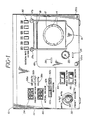
- Referring to FIGURE 1, a
peristaltic pump module 10 constructed in accordance with the principles of the present invention is shown. A constructed embodiment of this module has been built as a modular add-on to the SITE TXR* system. This mainframe system includes a chassis which can accommodate a number of modules that perform different functions for the ophthalmic surgeon, including the control of surgical cutting instruments and infusion and aspiration. The module shown in FIGURE l is representative of one of these modules which provides infusion and peristaltic pump aspiration. - On the
front panel 11 of the module are a number of controls and displays. A concentric switch includes acenter knob 32 which turns the module on and is adjustable to set the maximum suction level to be applied by the peristaltic pump. As theknob 32 is adjusted the numbers displayed by thepreset vacuum display 34 will vary to indicate the setting of the maximum vacuum. Theouter knob 36 is adjustable to one of three settings: mm Hg, in. H₂O, and in. Hg. The setting ofknob 36 illuminates one of threecorresponding lights displays display 40 constantly displays the vacuum level at the inlet (suction) line to the peristaltic pump. A pressure sensor accesses the suction line through aport 22. - Three
pushbuttons pushbutton 42c is depressed, the infusion line is opened automatically whenever a control pedal (not shown) is depressed to start the pump, and is automatically occluded by the extension of a solenoid actuated interrupter bar through opening 26 when the control pedal is released. The other two pushbuttons provide manual control of the infusion line. When "closed" pushbutton 42a is depressed, the interrupter bar extends to occlude the infusion line, and when "open"pushbutton 42b is depressed the interrupter bar retracts to open the line The control functions ofpushbuttons 42a and 42b operate independently of the control pedal. - The pump speed, and hence the rate at which the vacuum level is developed by the pump, is set by depressing one of
pushbuttons 30. Each pushbutton controls the suction rate, as measured in cubic centimeters of flow per minute through an unblocked suction line. Two types of suction control are available. When the "fixed suction"switch 44 is set, the pump will immediately begin pumping at the preset suction rate when the control pedal is depressed. When the "linear suction" switch 46 is set, the operator can accelerate the suction rate up to the preset rate by controllably depressing the control pedal. - The pump mechanism includes a brushless DC motor and gearbox located within the module which rotates a
pump head 12. Evenly spaced around the pump head are sixrollers 14. The pump head is turned in a clockwise direction by the motor so that the rollers will sequentially and smoothly squeeze the pump tubing as they pass along the upper quadrant of the pump head location. - The pump cassette, to be described below, is affixed in an area outlined by 48. The cassette is supported at the bottom by the placement of tabs at the bottom corners of the cassette in two retaining
brackets cam bar 18 at the top of the cassette. The cam bar is secured between the sides of alatch 16, which is pivotally connected to latchsupports area 48. When the cassette is placed in position with its tabs located in thebrackets - A second solenoid actuated interrupter bar controllably extends through opening 28 in the front panel to selectively open or occlude a vent line to the suction line of the cassette.
- Referring to FIGURES 2 - 4, views of the outside of a
cassette 50 suitable for use with themodule 10 are shown. FIGURE 2 illustrates thefront surface 51 of the cassette. The cassette is characterized by anoval opening 56 which accommodates the pump head. The width and arc of theopening 56 are sized to be just slightly larger than the pump head. - Located at the top of the cassette is an
inlet luer 68 of the infusion line. The infusion line exits the cassette throughtubing 64. Thetubing 64 is connected to a barbed fitting within the cassette. This connection is protected by a moldedguard 66 which projects from thefront 51 of the cassette. Theguard 66 is also shown in FIGURE 4. Theinfusion tubing 64 terminates in aluer 81, by which the tubing may be connected to the infusion port of an infusion/aspiration handpiece or a surgical cutting instrument. - A
suction tubing line 60 has a moldedadapter piece 80 connected at its free end for connection to the suction, or aspiration, port of the handpiece or instrument.Tubing 60 is similarly connected to a barbed fitting within the cassette which is protected by a moldedguard 62. The suction line passes through the cassette and makes a transition to apump tubing segment 58. Thetubing segment 58 enters theopening 56 through an aperture in the interior wall of the opening, passes along the inside wall along its upper arc, and exits the opening through an aperture in the interior wall on the opposite end of the arc from which it entered. The tubing segment is made of a material suitable for use in a peristaltic pump, such as silicone. In a constructed embodiment, this tubing segment has a 1/8 inch inner diameter and a 1/4 inch outer diameter. - The
tubing segment 58 exits the cassette through a hole in the bottom, from which it leads to a means for disposing of aspirated material such as a drain bag. - Along each vertical side of the
cassette 50, the body of the cassette is thinned to formcorner tabs brackets module 10. - FIGURE 3 shows the
back surface 53 of thecassette 50, including the previously described infusionline inlet luer 68, theopening 56, and pumptubing segment 58. Also shown are anaperture 76 through which the interrupter bar of opening 26 enters the cassette, and anaperture 78 for passage of the interrupter bar ofopening 28. A vent line tubing segment is visible throughaperture 78, and an infusion line tubing segment is visible throughaperture 76. There is ahole 94 through the back of the cassette for passage of apressure sensing port 82, which mates with theport 22 when the cassette is mounted on themodule 10. Theport 82 is surrounded by afoam sealing gasket 84. - FIGURE 4 is a bottom view of the
cassette 50, which is seen to be comprised of afront half 52 and aback half 54.Guards front surface 51 are shown at the top of the drawing.Aperture 74 is provided for passage oftubing segment 58, which for clarity is not represented in FIGURE 4.Aperture 72 is an opening for the vent line. On either side of the cassette bottom thecorner tabs - Referring to FIGURE 5, the interior of the
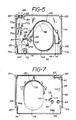
back cassette half 54 is shown, with tubing segments and ajunction block 150 drawn in phantom for ease of illustration. Theinfusion luer 68 enters the top of the cassette through a semicircular aperture in ablock 90. Theblock 90 includes arectangular opening 92 which retains a collar of theluer 68 to hold the luer in place. An infusionline tubing segment 140 extends from theluer 68 to thejunction block 150. Thetubing segment 140 passes over theinterrupter bar aperture 76, and is maintained in this position by four molded guides 77a-77d.Vent tubing segment 174 extends from thejunction block 150 to theaperture 72 and passes over theinterrupter bar aperture 78. - The
pump tubing segment 58 is retained in its intended position by a moldedupper guide 100 and the opposite ends of a moldedlower guide 102. A curved, moldedprotrusion 104 spans the two guides proximate thejunction block 150 to serve as a portion of an integral clamp which secures thetubing segment 58 on its junction block fitting. A molded bracket withholes protrusion 104 mates with pins in the front cassette half to secure the integral tubing clamp. - A portion of the
upper guide 100 is seen to be contiguous with the upper arc of theopening 56. This portion of the guide serves two further purposes: it forms the upper interior wall of theopening 56, and it is the surface against which thetubing segment 58 is compressed by the pump head. The central portion of thelower guide 102 similarly is contiguous with the perimeter of theopening 56, and likewise forms the side and lower arcuate interior walls of the opening. It may be seen that the spaces between the two guides at their intersections with the opening perimeter form the apertures through which thepump tubing segment 58 enters and exits theopening 56. - Located at the upper two corners of the
back cassette half 54 and just above each of thetabs holes 122 which mate with pins of thefront cassette half 52. - FIGURE 7 shows the interior of the
front cassette half 52. Ablock 90′ with anopening 92′ mates withblock 90 of the back cassette half to capture theluer 68 and its collar. Aprotrusion 86 forms an anvil surface for occludingtubing segment 140. The interrupter bar entering the cassette throughaperture 76 will squeeze and thereby occlude the infusionline tubing segment 140 between the interrupter bar and theprotrusion 86. Below theprotrusion 86 are two holes through which the moldedguards guard 62 for the suction line is a protrusion forming ananvil surface 88. The interrupterbar entering aperture 78 occludes thevent tubing segment 174 between theprotrusion 88 and the interrupter bar. - Curved protrusion 114 extends to form the second half of the integral clamp which secures
tubing segment 58 on its junction block fitting when the two cassette halves are mated together.Pins holes protrusion 134 fits between the ends of theguides tubing segment 58 leaves the two guides. - Located around the upper arc of the
opening 56 is a reinforcedsupport wall 130. Thesupport wall 130 is spaced slightly above the perimeter of the opening so that theupper guide 100 of the back cassette half will fit flush againstsurface 132 of the support wall. The support wall thus supports the upper arcuate portion of theguide 100 where it opposes the compressive forces of the pump head rollers as thetubing segment 58 is compressed. - Located at the upper corners of the front cassette half and just above the tab locations are
pins 120, which mate with theholes 122 in the back cassette half. It may be seen that when the two cassette halves are mated together, they are fastened to each other by the fourpins 120, pins 110 and 112, and their respective holes. - FIGURE 6 illustrates the cassette tubing segments and junction block which were shown in phantom in FIGURE 5, and in the same configuration. FIGURE 6 clearly shows the
collar 98 of the infusion linefemale luer 68 which fits into therectangular openings aperture 76 behind the infusionline tubing segment 140 in an assembled cassette. The infusionline tubing segment 140 is connected to a luer 152 on thejunction block 150, and thevent tubing segment 174 is connected to aluer 156 on the junction block. The location ofaperture 78 relative to the vent tubing segment in an assembled cassette is indicated byphantom lines 78′. - The
pump tubing segment 58 is connected to a fitting 154 on the junction block. The fitting 154 has a narrow diameter neck, about which the integral clamp of the cassette secures the tubing segment to the fitting 154.Barbed fittings infusion tubing 64 andsuction tubing 60. Thefittings junction block 150. - In FIGURE 6a, the fluid passageways through the
junction block 150 can be seen. Apassageway 142 for the infusion line enters the junction block through fitting 152 on the back of the block as it is oriented in FIGURE 6a, and continues through thebarbed fitting 160. A suction line passageway 166 passes through thebarbed fitting 162 and continues through the fitting 154. The extension of passageway 166 to the bottom of the junction block in FIGURE 6a forms thepressure sensing port 82. Thepressure sensing port 82 is surrounded by a raised mountingsurface 164 for the sealinggasket 84 of FIGURE 3. The diameter ofsurface 164, shown in phantom in FIGURE 6, is sized to just fit into thehole 94 in the back half of the cassette (FIGURES 3 and 5). - FIGURE 8 illustrates a side view of the
cassette 50 when mounted for operation on themodule 10. The mounted cassette is supported at the bottom by the placement of thecorner tabs brackets back surface 53 flush against thefront panel 11 of the module. In this position thepump head 12 extends throughopening 56. The cassette is slightly raised from its final vertical alignment, as thetubing segment 58 is resting uncompressed between thepump head 12 and theguide wall 100. - To lower the cassette to its intended vertical alignment with the module, the
latch 16 is pivoted downward over the cassette. This causes thecam bar 18 to first contact the upper front edge of the cassette, then to forcibly roll on to the top of the cassette, as shown in FIGURE 8. Thecam bar 18 thus presses the cassette downward with thecorner tabs tubing segment 58 between theguide wall 100 and therollers 14 of thepump head 12. Theinterrupter bar apertures corresponding apertures pressure sensing ports - The pump cassette system is now ready for operation. Referring to FIGURE 1, the user sets the preset vacuum level with the
knob 32 and its units of display with theknob 36. The suction rate is set by pressing one ofpushbuttons 30, and the mode of suction control is set by setting one ofswitches 44 and 46. The infusion line may be controlled automatically by depressingpushbutton 42c, or pushbutton 42a may be pressed to close the infusion line until it is needed. - The fluid lines are connected by connecting a source of infusion liquid to the
female luer 68. Generally, this will be a bag or bottle of liquid suspended above the module.Luer 81 andadapter 80 oftubing lines - In operation with automatic infusion line control, where the control pedal is depressed the infusion line interrupter bar retracts to open the infusion line tubing segment. This occlusion control technique is the same as that used by the interrupter bars described in U.S. Patent 4,493,695. Infusion liquid then flows through
tubing segment 140, thejunction block passageway 142, thebarbed luer 160, and into theinfusion tubing 64. Further depression of the control pedal causes the pump head to begin rotating, either immediately at its selected rate when fixed suction is set, or at a controlled accelerating rate to the selected rate if linear suction is called for. Suction then begins to build in thesuction tubing line 60, and is continuously monitored at theport 82 of the junction block by the module's internal pressure sensor. The pump head continues to rotate so long as the pump is freely pumping liquid. When the actual vacuum level reaches the preset vacuum level, as would occur if the suction port of the instrument or handpiece becomes fully occluded with particles of tissue, the pump head rotation stops until the actual vacuum level falls to a predetermined level, such as 80% of the preset maximum level. At this point the pump head resumes its rotation to aspirate the tissue particles through the suction tubing line and away from the surgical site. Thus, there is no buildup of substantial suction pressure at the handpiece or instrument tip until an occlusion of the suction line occurs. This prevents the application of undesired suction pressures to the patient at the surgical site, and eliminates any tendency of the hand-held instrument to "grab" tissue, as would happen if continual suction were applied. The physician thus is more easily able to precisely control the instrument during the surgical procedure. - When the depressed control pedal is released by the physician, the
infusion tubing segment 140 is occluded and the interrupter bar extending throughaperture 78 of the cassette is momentarily retracted, opening thevent tubing segment 174 and equalizing the suction line vacuum to atmospheric pressure. The handpiece or instrument can then be moved about the surgical site without exposing the patient to any residual vacuum pressures in the suction line. If desired, the pump head may be momentarily rotated counterclockwise by depressing a button adjacent to the control pedal to expel any blockage from the tip of the handpiece or surgical instrument.
Claims (20)
roller head means for performing peristaltic and
removable cassette means for retaining a tubing section which cooperates with said roller head means in the performance of peristaltic pumping, said cassette means having an aperture passing therethrough for engaging said roller head means so that said cassette radially surrounds said roller head means with said tubing section located between said roller head means and an interior wall of said cassette defining said aperture, said cassette further including a selectably occludable infusion line passing therethrough.
a control system having an outer panel;
roller head means, located on said outer panel, for performing peristaltic pumping; and
a disposable pump cassette, suitable for mounting on said outer panel so as to engage said roller head means, and including a tubing section located between said roller head means and an arcuate surface of said cassette when said cassette engages said roller head means, said cassette further including a selectably occludable infusion line which passes therethrough.
wherein said outer panel further includes means for selectively occluding said vent tubing line and means for connecting a sensor in fluid communication with said suction sensing port.
a controller, including roller head means for performing peristaltic pumping, and actuator means for controllably occluding a vent line; and
a disposable cassette, including a pump tubing section and a vent line tubing section in fluid communication with said pump tubing section, said cassette being suitable for engaging said roller head means with said pump tubing section located between said roller head means and a wall of said cassette, and said vent line tubing section opposing said actuator means when said cassette engages said roller head means, wherein said vent tubing section may be selectively occluded when compressed between said actuator means and said cassette.
wherein said controller further includes actuator means for controllably occluding an infusion line; and
wherein said cassette includes a selectively occludable infusion line.
a console, including roller head means for performing peristaltic pumping, bracket means for engaging a pump tubing cassette, and latch means for applying a compressive force to a pump tubing cassette; and
a pump tubing cassette, including an opening for engaging said roller head means, a pump tubing section located in said opening and opposing a wall of said cassette, and tab means, located on a first side of said cassette for engaging said bracket means,
wherein said latch means applies a compressive force to a second side of said cassette to maintain the engagement of said tab means and said bracket means, and to compress said pump tubing section between said wall and said roller head means.
a disposable cassette having an opening for engaging a roller head, a pump tubing section located in said opening and opposing a wall of said opening, tab means located on one side of said cassette for engaging bracket means for mounting said cassette on a roller head console, and an irrigation tubing segment extending through said cassette.
a disposable cassette having a body exhibiting a thickness, and exhibiting major dimensions located in a plane defined by the height and width of said cassette body, an opening in said body for engaging a roller head, a pump tubing section extending through at least a portion of said opening and opposing a wall thereof, an irrigation tubing segment extending through said cassette with an occludable portion of said irrigation tubing segment located parallel to said plane, and a suction measuring line in fluid communication with said pump tubing section and having an opening in a plane which is parallel to said plane of said cassette body.
Applications Claiming Priority (2)
| Application Number | Priority Date | Filing Date | Title |
|---|---|---|---|
| US07/043,120 US4798580A (en) | 1987-04-27 | 1987-04-27 | Disposable peristaltic pump cassette system |
| US43120 | 1987-04-27 |
Publications (2)
| Publication Number | Publication Date |
|---|---|
| EP0293081A1 true EP0293081A1 (en) | 1988-11-30 |
| EP0293081B1 EP0293081B1 (en) | 1992-06-17 |
Family
ID=21925606
Family Applications (1)
| Application Number | Title | Priority Date | Filing Date |
|---|---|---|---|
| EP88303734A Expired - Lifetime EP0293081B1 (en) | 1987-04-27 | 1988-04-26 | Disposable peristaltic pump cassette system |
Country Status (7)
| Country | Link |
|---|---|
| US (1) | US4798580A (en) |
| EP (1) | EP0293081B1 (en) |
| JP (1) | JP2839501B2 (en) |
| KR (1) | KR960005813B1 (en) |
| AU (1) | AU603436B2 (en) |
| CA (1) | CA1310239C (en) |
| DE (1) | DE3872053T2 (en) |
Cited By (15)
| Publication number | Priority date | Publication date | Assignee | Title |
|---|---|---|---|---|
| WO1991015149A1 (en) * | 1990-04-04 | 1991-10-17 | Cableries & Trefileries De Cossonay S.A. | Device for continuously irrigating and draining human or animal body tissues or cavities |
| EP0459113A1 (en) * | 1990-05-04 | 1991-12-04 | Joseph Bertoncini | Peristaltic pump and method for adjustable flow regulation |
| WO1993000941A2 (en) * | 1991-07-09 | 1993-01-21 | Haemonetics Corporation | Blood processor with disposable cassette |
| WO1993024082A1 (en) * | 1992-06-03 | 1993-12-09 | Allergan, Inc. | Tubing management system |
| WO1994003729A1 (en) * | 1992-08-05 | 1994-02-17 | Government Of The United States As Represented By The Secretary, Department Of Health And Human Services | Miniature mechanical vacuum pump |
| EP0601313A2 (en) * | 1992-11-06 | 1994-06-15 | GRIESHABER & CO. AG SCHAFFHAUSEN | Device for microsurgery on the eye of a living creature |
| US5591127A (en) * | 1994-01-28 | 1997-01-07 | Barwick, Jr.; Billie J. | Phacoemulsification method and apparatus |
| EP0944404A1 (en) * | 1996-10-25 | 1999-09-29 | Arthur D. Little, Inc. | Fluid flow control system incorporating a disposable pump cartridge |
| US6059765A (en) * | 1998-02-26 | 2000-05-09 | Allergan Sales, Inc. | Fluid management system with vertex chamber |
| US6585683B2 (en) | 2001-09-19 | 2003-07-01 | Advanced Medical Optics, Inc. | Tubing management manifold with tubing captures |
| US7934912B2 (en) | 2007-09-27 | 2011-05-03 | Curlin Medical Inc | Peristaltic pump assembly with cassette and mounting pin arrangement |
| US8062008B2 (en) | 2007-09-27 | 2011-11-22 | Curlin Medical Inc. | Peristaltic pump and removable cassette therefor |
| US8083503B2 (en) | 2007-09-27 | 2011-12-27 | Curlin Medical Inc. | Peristaltic pump assembly and regulator therefor |
| WO2018054833A2 (en) | 2016-09-20 | 2018-03-29 | Medela Holding Ag | Suctioning and supply device with drive unit and connecting part |
| US11644026B2 (en) | 2016-09-20 | 2023-05-09 | Medela Holding Ag | Device for suctioning bodily fluids and for supplying a substance |
Families Citing this family (156)
| Publication number | Priority date | Publication date | Assignee | Title |
|---|---|---|---|---|
| US5157603A (en) * | 1986-11-06 | 1992-10-20 | Storz Instrument Company | Control system for ophthalmic surgical instruments |
| US5125891A (en) * | 1987-04-27 | 1992-06-30 | Site Microsurgical Systems, Inc. | Disposable vacuum/peristaltic pump cassette system |
| US5201711A (en) * | 1987-09-30 | 1993-04-13 | Sherwood Medical Company | Safety interlock system for medical fluid pumps |
| US4904168A (en) * | 1988-12-28 | 1990-02-27 | United Sonics, Inc. | Cassette assembly for ophthalmic surgery system |
| US5163900A (en) * | 1989-03-16 | 1992-11-17 | Surgin Surgical Instrumentation, Inc. | Disposable cassette systems |
| US5134994A (en) * | 1990-02-12 | 1992-08-04 | Say Sam L | Field aspirator in a soft pack with externally mounted container |
| US5106366A (en) * | 1990-03-08 | 1992-04-21 | Nestle, S.A. | Medical fluid cassette and control system |
| US5094820A (en) * | 1990-04-26 | 1992-03-10 | Minnesota Mining And Manufacturing Company | Pump and calibration system |
| US5147313A (en) * | 1990-10-22 | 1992-09-15 | Entracare Corporation | Medical fluid delivery system with uniquely configured pump unit and fluid delivery set |
| US5236004A (en) * | 1991-04-03 | 1993-08-17 | Sherwood Medical Company | Ambulatory support device for a fluid delivery system |
| US5213483A (en) * | 1991-06-19 | 1993-05-25 | Strato Medical Corporation | Peristaltic infusion pump with removable cassette and mechanically keyed tube set |
| US5267956A (en) * | 1992-02-05 | 1993-12-07 | Alcon Surgical, Inc. | Surgical cassette |
| US5499969A (en) * | 1992-02-05 | 1996-03-19 | Nestle S.A. | Microsurgical cassette |
| WO1993017729A1 (en) * | 1992-03-03 | 1993-09-16 | Alcon Surgical, Inc. | System and apparatus for controlling fluid flow from a surgical handpiece |
| US5947167A (en) * | 1992-05-11 | 1999-09-07 | Cytologix Corporation | Dispensing assembly with interchangeable cartridge pumps |
| US20040191128A1 (en) * | 1992-05-11 | 2004-09-30 | Cytologix Corporation | Slide stainer with heating |
| US5645114A (en) * | 1992-05-11 | 1997-07-08 | Cytologix Corporation | Dispensing assembly with interchangeable cartridge pumps |
| US5316452A (en) * | 1992-05-11 | 1994-05-31 | Gilbert Corporation | Dispensing assembly with interchangeable cartridge pumps |
| US6180061B1 (en) | 1992-05-11 | 2001-01-30 | Cytologix Corporation | Moving platform slide stainer with heating elements |
| US5342181A (en) * | 1992-06-15 | 1994-08-30 | Datascope Investment Corp. | Single roller blood pump and pump/oxygenator system using same |
| US5230704A (en) * | 1992-06-26 | 1993-07-27 | Biomedical Dynamics Corporation | Suction/irrigation instrument having reusable handle with disposable fluid path |
| US5324180A (en) * | 1992-09-04 | 1994-06-28 | Allergan, Inc. | Surgical instrument with drawer loading cassette system |
| US5685821A (en) * | 1992-10-19 | 1997-11-11 | Arthrotek | Method and apparatus for performing endoscopic surgical procedures |
| US5403277A (en) * | 1993-01-12 | 1995-04-04 | Minnesota Mining And Manufacturing Company | Irrigation system with tubing cassette |
| US5626563A (en) * | 1993-01-12 | 1997-05-06 | Minnesota Mining And Manufacturing Company | Irrigation system with tubing cassette |
| US5342293A (en) * | 1993-06-22 | 1994-08-30 | Allergan, Inc. | Variable vacuum/variable flow phacoemulsification method |
| US5447417A (en) * | 1993-08-31 | 1995-09-05 | Valleylab Inc. | Self-adjusting pump head and safety manifold cartridge for a peristaltic pump |
| US5423749A (en) * | 1993-11-18 | 1995-06-13 | Minnesota Mining And Manufacturing Company | Cardioplegia administration system and method |
| US5464391A (en) * | 1994-03-03 | 1995-11-07 | Northgate Technologies Inc. | Irrigation system for a surgical site |
| US5609575A (en) * | 1994-04-11 | 1997-03-11 | Graseby Medical Limited | Infusion pump and method with dose-rate calculation |
| US5460490A (en) * | 1994-05-19 | 1995-10-24 | Linvatec Corporation | Multi-purpose irrigation/aspiration pump system |
| US5624394A (en) * | 1994-10-28 | 1997-04-29 | Iolab Corporation | Vacuum system and a method of operating a vacuum system |
| US5810766A (en) * | 1995-02-28 | 1998-09-22 | Chiron Vision Corporation | Infusion/aspiration apparatus with removable cassette |
| US5637093A (en) * | 1995-03-06 | 1997-06-10 | Sabratek Corporation | Infusion pump with selective backlight |
| US5620312A (en) * | 1995-03-06 | 1997-04-15 | Sabratek Corporation | Infusion pump with dual-latching mechanism |
| US5795327A (en) * | 1995-03-06 | 1998-08-18 | Sabratek Corporation | Infusion pump with historical data recording |
| US5904668A (en) * | 1995-03-06 | 1999-05-18 | Sabratek Corporation | Cassette for an infusion pump |
| US5628619A (en) * | 1995-03-06 | 1997-05-13 | Sabratek Corporation | Infusion pump having power-saving modes |
| USD380260S (en) * | 1995-03-06 | 1997-06-24 | Sabratek Corporation | Infusion pump |
| US5569188A (en) * | 1995-04-11 | 1996-10-29 | Mackool; Richard J. | Apparatus for controlling fluid flow through a surgical instrument and the temperature of an ultrasonic instrument |
| US5693008A (en) * | 1995-06-07 | 1997-12-02 | Cobe Laboratories, Inc. | Dialysis blood tubing set |
| US5588815A (en) * | 1995-11-15 | 1996-12-31 | Alcon Laboratories, Inc. | Surgical cassette loading and unloading system |
| US5800396A (en) * | 1995-11-15 | 1998-09-01 | Alcon Laboratories, Inc. | Surgical cassette adapter |
| US5899674A (en) * | 1995-12-01 | 1999-05-04 | Alcon Laboratories, Inc. | Indentification system for a surgical cassette |
| US6059544A (en) * | 1995-12-01 | 2000-05-09 | Alcon Laboratories, Inc. | Identification system for a surgical cassette |
| CA2186805C (en) * | 1995-12-01 | 2001-03-27 | Christopher C. Jung | Apparatus and method for sensing fluid level |
| US5676530A (en) * | 1996-01-24 | 1997-10-14 | Alcon Laboratories, Inc. | Surgical cassette latching mechanism |
| US6171298B1 (en) | 1996-05-03 | 2001-01-09 | Situs Corporation | Intravesical infuser |
| US5718238A (en) * | 1996-09-11 | 1998-02-17 | Storz Instrument Company | Fluid collection cassette identification scheme |
| US6179829B1 (en) | 1997-08-28 | 2001-01-30 | Bausch & Lomb Surgical, Inc. | Foot controller for microsurgical system |
| US6280406B1 (en) | 1997-09-12 | 2001-08-28 | Gambro, Inc | Extracorporeal blood processing system |
| US7776014B2 (en) | 1998-01-29 | 2010-08-17 | Peter Visconti | Disposable surgical suction/irrigation trumpet valve tube cassette |
| US6183693B1 (en) * | 1998-02-27 | 2001-02-06 | Cytologix Corporation | Random access slide stainer with independent slide heating regulation |
| US6468242B1 (en) | 1998-03-06 | 2002-10-22 | Baxter International Inc. | Medical apparatus with patient data recording |
| US6183461B1 (en) | 1998-03-11 | 2001-02-06 | Situs Corporation | Method for delivering a medication |
| US6290690B1 (en) | 1999-06-21 | 2001-09-18 | Alcon Manufacturing, Ltd. | Simultaneous injection and aspiration of viscous fluids in a surgical system |
| US6740074B2 (en) | 1999-08-31 | 2004-05-25 | Alcon, Inc. | Liquid venting surgical cassette |
| US6962488B2 (en) * | 1999-11-10 | 2005-11-08 | Alcon, Inc. | Surgical cassette having an aspiration pressure sensor |
| US20040253129A1 (en) * | 1999-08-31 | 2004-12-16 | Sorensen Gary P. | Liquid venting surgical cassette |
| US6902542B2 (en) * | 2002-05-28 | 2005-06-07 | Alcon, Inc. | Identification system for a surgical cassette |
| US6293926B1 (en) | 1999-11-10 | 2001-09-25 | Alcon Universal Ltd. | Peristaltic pump and cassette |
| US6261283B1 (en) | 1999-08-31 | 2001-07-17 | Alcon Universal Ltd. | Liquid venting surgical system and cassette |
| US20030225366A1 (en) * | 1999-08-31 | 2003-12-04 | Morgan Michael D. | Liquid venting surgical cassette |
| DE19960668C1 (en) * | 1999-12-15 | 2001-08-16 | W O M Gmbh Physikalisch Medizi | Hose cassette for a peristaltic pump |
| US6497676B1 (en) * | 2000-02-10 | 2002-12-24 | Baxter International | Method and apparatus for monitoring and controlling peritoneal dialysis therapy |
| KR100379734B1 (en) * | 2000-12-15 | 2003-04-11 | 메딕스얼라인 주식회사 | apparatus for the treatment of intussusception |
| US20030125662A1 (en) * | 2002-01-03 | 2003-07-03 | Tuan Bui | Method and apparatus for providing medical treatment therapy based on calculated demand |
| US7070578B2 (en) * | 2002-04-25 | 2006-07-04 | Alcon, Inc. | Surgical cassette latching mechanism |
| US6908451B2 (en) | 2002-04-25 | 2005-06-21 | Alcon, Inc. | Liquid venting surgical system |
| US7153286B2 (en) * | 2002-05-24 | 2006-12-26 | Baxter International Inc. | Automated dialysis system |
| US7175606B2 (en) * | 2002-05-24 | 2007-02-13 | Baxter International Inc. | Disposable medical fluid unit having rigid frame |
| US20030217957A1 (en) * | 2002-05-24 | 2003-11-27 | Bowman Joseph H. | Heat seal interface for a disposable medical fluid unit |
| US20030220607A1 (en) * | 2002-05-24 | 2003-11-27 | Don Busby | Peritoneal dialysis apparatus |
| US7087036B2 (en) * | 2002-05-24 | 2006-08-08 | Baxter International Inc. | Fail safe system for operating medical fluid valves |
| US6764761B2 (en) * | 2002-05-24 | 2004-07-20 | Baxter International Inc. | Membrane material for automated dialysis system |
| US20030225363A1 (en) * | 2002-05-28 | 2003-12-04 | Raphael Gordon | Surgical cassette |
| US7238164B2 (en) * | 2002-07-19 | 2007-07-03 | Baxter International Inc. | Systems, methods and apparatuses for pumping cassette-based therapies |
| US7527608B2 (en) * | 2002-08-12 | 2009-05-05 | Lma North America, Inc. | Medication infusion and aspiration system and method |
| US20040092800A1 (en) * | 2002-11-11 | 2004-05-13 | Mackool Richard J. | System for instructing removal of cataract tissue |
| US7168930B2 (en) * | 2003-09-29 | 2007-01-30 | Bausch & Lomb Incorporated | Peristaltic pump with air venting via the movement of a pump head or a backing plate during surgery |
| US7445436B2 (en) * | 2003-09-29 | 2008-11-04 | Bausch & Lomb Incorporated | Peristaltic pump with a moveable pump head |
| US7662139B2 (en) * | 2003-10-30 | 2010-02-16 | Deka Products Limited Partnership | Pump cassette with spiking assembly |
| US8158102B2 (en) * | 2003-10-30 | 2012-04-17 | Deka Products Limited Partnership | System, device, and method for mixing a substance with a liquid |
| US7461968B2 (en) * | 2003-10-30 | 2008-12-09 | Deka Products Limited Partnership | System, device, and method for mixing liquids |
| US8029454B2 (en) | 2003-11-05 | 2011-10-04 | Baxter International Inc. | High convection home hemodialysis/hemofiltration and sorbent system |
| US20050209563A1 (en) * | 2004-03-19 | 2005-09-22 | Peter Hopping | Cassette-based dialysis medical fluid therapy systems, apparatuses and methods |
| US7758491B2 (en) * | 2004-04-05 | 2010-07-20 | Genesee Biomedical, Inc. | Method and apparatus for the surgical treatment of congestive heart failure |
| EP1662142A1 (en) * | 2004-11-26 | 2006-05-31 | Debiotech S.A. | Peristaltic pump |
| US20060216172A1 (en) * | 2004-12-16 | 2006-09-28 | Fitzgerald Matthew J | Peristaltic pump cartridge with tube standoff |
| US20070073250A1 (en) * | 2005-07-08 | 2007-03-29 | Schneiter James A | Implantable port |
| US8398582B2 (en) * | 2005-10-27 | 2013-03-19 | Novartis Ag | Fluid pressure sensing chamber |
| US8202243B2 (en) * | 2005-10-27 | 2012-06-19 | Novartis Ag | Fluid pressure sensing chamber |
| US20070098579A1 (en) * | 2005-10-27 | 2007-05-03 | Alcon, Inc. | Fluid pressure sensing chamber |
| US20070106301A1 (en) * | 2005-11-09 | 2007-05-10 | Alcon, Inc. | Sclerotomy adapter |
| US8011905B2 (en) * | 2005-11-17 | 2011-09-06 | Novartis Ag | Surgical cassette |
| US8182241B2 (en) * | 2005-12-20 | 2012-05-22 | G.H. Stenner & Co., Inc. | Peristaltic pumping mechanism having a removable cover and replaceable tubing, rollers and pumping mechanism |
| US7942853B2 (en) * | 2006-01-11 | 2011-05-17 | Alcon, Inc. | Fluid chamber |
| US7775780B2 (en) * | 2006-01-24 | 2010-08-17 | Alcon, Inc. | Surgical cassette |
| US20070180904A1 (en) * | 2006-02-06 | 2007-08-09 | Alcon, Inc. | Fluid level sensor |
| US20070180903A1 (en) * | 2006-02-09 | 2007-08-09 | Alcon, Inc. | Acoustic fluid level sensor |
| DE102006008325B4 (en) * | 2006-02-20 | 2013-09-12 | W.O.M. World Of Medicine Ag | Hose cassette for a peristaltic pump |
| US8079836B2 (en) * | 2006-03-01 | 2011-12-20 | Novartis Ag | Method of operating a peristaltic pump |
| US8343100B2 (en) | 2006-03-29 | 2013-01-01 | Novartis Ag | Surgical system having a non-invasive flow sensor |
| US9579429B2 (en) * | 2006-03-29 | 2017-02-28 | Novartis Ag | Surgical cassette with compliant clamping zone |
| US8251944B2 (en) | 2006-03-29 | 2012-08-28 | Novartis Ag | Surgical system having a cassette with an acoustic coupling |
| US7712802B2 (en) * | 2006-06-12 | 2010-05-11 | Alcon, Inc. | Cassette clamping mechanism |
| US7786457B2 (en) * | 2006-06-28 | 2010-08-31 | Alcon, Inc. | Systems and methods of non-invasive level sensing for a surgical cassette |
| US20080015515A1 (en) * | 2006-06-29 | 2008-01-17 | Mark Alan Hopkins | Top and bottom clamping for a surgical cassette |
| JP5415950B2 (en) | 2006-07-25 | 2014-02-12 | アルコン,インコーポレイティド | Surgical console operable to play multimedia content |
| US8465467B2 (en) * | 2006-09-14 | 2013-06-18 | Novartis Ag | Method of controlling an irrigation/aspiration system |
| WO2008060995A1 (en) | 2006-11-09 | 2008-05-22 | Advanced Medical Optics, Inc. | Reversible peristaltic pump and other structures for reflux in eye surgery |
| US7872746B2 (en) | 2006-12-22 | 2011-01-18 | Alcon, Inc. | Single light source uniform parallel light curtain |
| US8870812B2 (en) * | 2007-02-15 | 2014-10-28 | Baxter International Inc. | Dialysis system having video display with ambient light adjustment |
| US7998115B2 (en) * | 2007-02-15 | 2011-08-16 | Baxter International Inc. | Dialysis system having optical flowrate detection |
| US8361023B2 (en) * | 2007-02-15 | 2013-01-29 | Baxter International Inc. | Dialysis system with efficient battery back-up |
| US7731689B2 (en) | 2007-02-15 | 2010-06-08 | Baxter International Inc. | Dialysis system having inductive heating |
| US8558964B2 (en) | 2007-02-15 | 2013-10-15 | Baxter International Inc. | Dialysis system having display with electromagnetic compliance (“EMC”) seal |
| US9889239B2 (en) | 2007-03-23 | 2018-02-13 | Allegiance Corporation | Fluid collection and disposal system and related methods |
| AU2008232361B2 (en) | 2007-03-23 | 2013-05-16 | Allegiance Corporation | Fluid collection and disposal system and related methods |
| US8177776B2 (en) * | 2007-04-20 | 2012-05-15 | Doheny Eye Institute | Independent surgical center |
| US20100174415A1 (en) | 2007-04-20 | 2010-07-08 | Mark Humayun | Sterile surgical tray |
| US8323271B2 (en) * | 2007-04-20 | 2012-12-04 | Doheny Eye Institute | Sterile surgical tray |
| US8568391B2 (en) | 2007-04-20 | 2013-10-29 | Doheny Eye Institute | Sterile surgical tray |
| US8550310B2 (en) * | 2007-12-05 | 2013-10-08 | Bunn-O-Matic Corporation | Peristaltic pump |
| US8272857B2 (en) | 2008-02-22 | 2012-09-25 | Medtronic Xomed, Inc. | Method and system for loading of tubing into a pumping device |
| US8062513B2 (en) | 2008-07-09 | 2011-11-22 | Baxter International Inc. | Dialysis system and machine having therapy prescription recall |
| US9514283B2 (en) | 2008-07-09 | 2016-12-06 | Baxter International Inc. | Dialysis system having inventory management including online dextrose mixing |
| DE102009000299A1 (en) * | 2009-01-19 | 2010-07-22 | Robert Bosch Gmbh | peristaltic pump |
| DK2427228T3 (en) | 2009-05-06 | 2013-05-13 | Alcon Res Ltd | Multi segmented peristaltic pump and cartridge |
| US8388582B2 (en) | 2009-08-12 | 2013-03-05 | Medrad, Inc. | Systems and methods for operating interventional catheters using a common operating console and adaptive interface components |
| US9072540B2 (en) | 2009-08-12 | 2015-07-07 | Boston Scientific Limited | Adaptive tubing cassettes for use in connection with interventional catheter assemblies |
| AU2010226877B2 (en) * | 2009-09-24 | 2014-11-27 | Itt Manufacturing Enterprises, Inc. | Disposable pump head |
| US20110137231A1 (en) * | 2009-12-08 | 2011-06-09 | Alcon Research, Ltd. | Phacoemulsification Hand Piece With Integrated Aspiration Pump |
| DE102009058279B4 (en) | 2009-12-11 | 2016-05-12 | W. O. M. World of Medicine GmbH | Peristaltic peristaltic pump |
| US9239049B2 (en) | 2010-07-16 | 2016-01-19 | Boston Scientific Limited | Peristaltic pump having a self-closing occlusion bed |
| US8760637B2 (en) | 2010-08-30 | 2014-06-24 | Alcon Research, Ltd. | Optical sensing system including electronically switched optical magnification |
| US9700457B2 (en) * | 2012-03-17 | 2017-07-11 | Abbott Medical Optics Inc. | Surgical cassette |
| DE102012012525A1 (en) | 2012-06-26 | 2014-01-02 | Karl Storz Gmbh & Co. Kg | Pumping system, peristaltic pump and tube cassette as well as method for configuring a pumping system |
| DE102012105918A1 (en) * | 2012-07-03 | 2014-01-09 | B. Braun Avitum Ag | Multi-connector and medical device for extracorporeal blood treatment with multi-connector detection |
| DE102012105926A1 (en) * | 2012-07-03 | 2014-01-09 | B. Braun Avitum Ag | Hose roller pump with swiveling hose holder, and medical device for extracorporeal blood treatment |
| DE102012105919A1 (en) | 2012-07-03 | 2014-06-12 | B. Braun Avitum Ag | Tubular roller pump with pivoting lid and medical device for extracorporeal blood treatment with tube roller pump |
| US9445943B2 (en) | 2012-12-11 | 2016-09-20 | Alcon Research, Ltd. | Phacoemulsification hand piece with integrated aspiration and irrigation pump |
| US9713660B2 (en) | 2012-12-21 | 2017-07-25 | Alcon Research, Ltd. | Cassette clamp mechanism |
| US9962288B2 (en) | 2013-03-07 | 2018-05-08 | Novartis Ag | Active acoustic streaming in hand piece for occlusion surge mitigation |
| US9545337B2 (en) | 2013-03-15 | 2017-01-17 | Novartis Ag | Acoustic streaming glaucoma drainage device |
| US9693896B2 (en) | 2013-03-15 | 2017-07-04 | Novartis Ag | Systems and methods for ocular surgery |
| US9126219B2 (en) | 2013-03-15 | 2015-09-08 | Alcon Research, Ltd. | Acoustic streaming fluid ejector |
| US9750638B2 (en) | 2013-03-15 | 2017-09-05 | Novartis Ag | Systems and methods for ocular surgery |
| US9915274B2 (en) | 2013-03-15 | 2018-03-13 | Novartis Ag | Acoustic pumps and systems |
| US9962226B2 (en) | 2013-11-28 | 2018-05-08 | Alcon Pharmaceuticals Ltd. | Ophthalmic surgical systems, methods, and devices |
| JP2016538077A (en) | 2013-11-28 | 2016-12-08 | アルコン ファーマシューティカルズ リミティド | Ophthalmic surgery system, method and apparatus |
| CN111544671B (en) * | 2014-09-10 | 2023-09-08 | 3M创新知识产权公司 | Therapeutic device with integrated fluid conductor and noise attenuation |
| WO2017062874A1 (en) | 2015-10-09 | 2017-04-13 | Deka Products Limited Partnership | Fluid pumping and bioreactor system |
| WO2017112916A1 (en) | 2015-12-24 | 2017-06-29 | Hologic, Inc. | Uterine distension fluid management system with peristaltic pumps |
| US11299705B2 (en) | 2016-11-07 | 2022-04-12 | Deka Products Limited Partnership | System and method for creating tissue |
| US11179516B2 (en) | 2017-06-22 | 2021-11-23 | Baxter International Inc. | Systems and methods for incorporating patient pressure into medical fluid delivery |
Citations (2)
| Publication number | Priority date | Publication date | Assignee | Title |
|---|---|---|---|---|
| US4493695A (en) * | 1982-06-01 | 1985-01-15 | Site Microsurgical Systems, Inc. | Opthalmic microsurgical system cassette assembly |
| WO1986006964A1 (en) * | 1985-05-21 | 1986-12-04 | Coopervision, Inc. | Cassette for surgical irrigation and aspiration |
Family Cites Families (18)
| Publication number | Priority date | Publication date | Assignee | Title |
|---|---|---|---|---|
| US3723030A (en) * | 1971-03-03 | 1973-03-27 | Buchler Instr Division | Peristaltic pump with stacked components |
| US3841799A (en) * | 1971-08-23 | 1974-10-15 | East West Med Prod | Medical cassette pump |
| US4168707A (en) * | 1977-06-13 | 1979-09-25 | Douvas Nicholas G | Control apparatus for microsurgical instruments |
| US4187057A (en) * | 1978-01-11 | 1980-02-05 | Stewart-Naumann Laboratories, Inc. | Peristaltic infusion pump and disposable cassette for use therewith |
| US4256437A (en) * | 1978-02-01 | 1981-03-17 | Stewart Naumann Laboratories, Inc. | Peristaltic infusion pump and method |
| US4256442A (en) * | 1979-04-18 | 1981-03-17 | Baxter Travenol Laboratories, Inc. | Improved pressure plate movement system for a peristaltic pump |
| US4526515A (en) * | 1979-12-06 | 1985-07-02 | Baxter Travenol Laboratories, Inc. | Fluid pumping assembly including a prepackaged fluid circuit module |
| US4424011A (en) * | 1980-12-22 | 1984-01-03 | Triune Automated Painting Systems | Painting applicator with remote supply |
| US4515589A (en) * | 1981-03-23 | 1985-05-07 | Austin Jon W | Peristaltic pumping method and apparatus |
| US4445826A (en) * | 1982-01-22 | 1984-05-01 | Polaroid Corporation | Peristaltic pump apparatus |
| US4482347A (en) * | 1982-08-12 | 1984-11-13 | American Hospital Supply Corporation | Peristaltic fluid-pumping apparatus |
| US4537561A (en) * | 1983-02-24 | 1985-08-27 | Medical Technology, Ltd. | Peristaltic infusion pump and disposable cassette for use therewith |
| US4685902A (en) * | 1983-08-24 | 1987-08-11 | Becton, Dickinson And Company | Disposable reservoir cassette |
| EP0226622A4 (en) * | 1985-06-05 | 1988-08-23 | Coopervision Inc | Connecting fitting of a fluid flow control system. |
| US4666598A (en) * | 1985-06-25 | 1987-05-19 | Cobe Laboratories, Inc. | Apparatus for use with fluid flow transfer device |
| US4599055A (en) * | 1985-06-25 | 1986-07-08 | Cobe Laboratories, Inc. | Peristaltic pump |
| US4735558A (en) * | 1986-04-08 | 1988-04-05 | Staar Surgical Company | Peristaltic pump latching mechanism |
| US4714464A (en) * | 1986-10-27 | 1987-12-22 | Entravision, Inc. | Mechanism for coupling the aspirant line of an irrigation/aspiration machine to the pressure monitoring section |
-
1987
- 1987-04-27 US US07/043,120 patent/US4798580A/en not_active Expired - Lifetime
-
1988
- 1988-04-26 JP JP63101505A patent/JP2839501B2/en not_active Expired - Fee Related
- 1988-04-26 DE DE8888303734T patent/DE3872053T2/en not_active Expired - Fee Related
- 1988-04-26 CA CA000565123A patent/CA1310239C/en not_active Expired - Fee Related
- 1988-04-26 AU AU15150/88A patent/AU603436B2/en not_active Ceased
- 1988-04-26 EP EP88303734A patent/EP0293081B1/en not_active Expired - Lifetime
- 1988-04-27 KR KR1019880004758A patent/KR960005813B1/en not_active IP Right Cessation
Patent Citations (2)
| Publication number | Priority date | Publication date | Assignee | Title |
|---|---|---|---|---|
| US4493695A (en) * | 1982-06-01 | 1985-01-15 | Site Microsurgical Systems, Inc. | Opthalmic microsurgical system cassette assembly |
| WO1986006964A1 (en) * | 1985-05-21 | 1986-12-04 | Coopervision, Inc. | Cassette for surgical irrigation and aspiration |
Cited By (25)
| Publication number | Priority date | Publication date | Assignee | Title |
|---|---|---|---|---|
| WO1991015149A1 (en) * | 1990-04-04 | 1991-10-17 | Cableries & Trefileries De Cossonay S.A. | Device for continuously irrigating and draining human or animal body tissues or cavities |
| US5246422A (en) * | 1990-04-04 | 1993-09-21 | Ferton Holding | Device for continuously irrigating and draining human or animal body tissues or cavities |
| EP0459113A1 (en) * | 1990-05-04 | 1991-12-04 | Joseph Bertoncini | Peristaltic pump and method for adjustable flow regulation |
| US5318413A (en) * | 1990-05-04 | 1994-06-07 | Biomedical Research And Development Laboratories, Inc. | Peristaltic pump and method for adjustable flow regulation |
| WO1993000941A2 (en) * | 1991-07-09 | 1993-01-21 | Haemonetics Corporation | Blood processor with disposable cassette |
| WO1993000941A3 (en) * | 1991-07-09 | 1993-03-18 | Haemonetics Corp | Blood processor with disposable cassette |
| US5273517A (en) * | 1991-07-09 | 1993-12-28 | Haemonetics Corporation | Blood processing method and apparatus with disposable cassette |
| WO1993024082A1 (en) * | 1992-06-03 | 1993-12-09 | Allergan, Inc. | Tubing management system |
| WO1994003729A1 (en) * | 1992-08-05 | 1994-02-17 | Government Of The United States As Represented By The Secretary, Department Of Health And Human Services | Miniature mechanical vacuum pump |
| EP0601313A2 (en) * | 1992-11-06 | 1994-06-15 | GRIESHABER & CO. AG SCHAFFHAUSEN | Device for microsurgery on the eye of a living creature |
| EP0601313A3 (en) * | 1992-11-06 | 1994-08-17 | Grieshaber & Co Ag | Device for microsurgery on the eye of a living creature. |
| US5454783A (en) * | 1992-11-06 | 1995-10-03 | Grieshaber & Co Ag Schaffhausen | Apparatus for microsurgical operations on the eye of a living being |
| US5591127A (en) * | 1994-01-28 | 1997-01-07 | Barwick, Jr.; Billie J. | Phacoemulsification method and apparatus |
| US5700240A (en) * | 1994-01-28 | 1997-12-23 | Barwick, Jr.; Billie John | Phacoemulsification system having ultrasonic power controlled by aspiration vacuum sensor |
| EP0944404A1 (en) * | 1996-10-25 | 1999-09-29 | Arthur D. Little, Inc. | Fluid flow control system incorporating a disposable pump cartridge |
| EP0944404A4 (en) * | 1996-10-25 | 2001-08-29 | Little Inc A | Fluid flow control system incorporating a disposable pump cartridge |
| US6059765A (en) * | 1998-02-26 | 2000-05-09 | Allergan Sales, Inc. | Fluid management system with vertex chamber |
| US6585683B2 (en) | 2001-09-19 | 2003-07-01 | Advanced Medical Optics, Inc. | Tubing management manifold with tubing captures |
| US7934912B2 (en) | 2007-09-27 | 2011-05-03 | Curlin Medical Inc | Peristaltic pump assembly with cassette and mounting pin arrangement |
| US8062008B2 (en) | 2007-09-27 | 2011-11-22 | Curlin Medical Inc. | Peristaltic pump and removable cassette therefor |
| US8083503B2 (en) | 2007-09-27 | 2011-12-27 | Curlin Medical Inc. | Peristaltic pump assembly and regulator therefor |
| WO2018054833A2 (en) | 2016-09-20 | 2018-03-29 | Medela Holding Ag | Suctioning and supply device with drive unit and connecting part |
| EP3610899A1 (en) | 2016-09-20 | 2020-02-19 | Medela Holding AG | Extraction and supply device with drive unit and connection piece |
| US11090417B2 (en) | 2016-09-20 | 2021-08-17 | Medela Holding Ag | Suctioning and supply device with drive unit and connecting part |
| US11644026B2 (en) | 2016-09-20 | 2023-05-09 | Medela Holding Ag | Device for suctioning bodily fluids and for supplying a substance |
Also Published As
| Publication number | Publication date |
|---|---|
| AU603436B2 (en) | 1990-11-15 |
| CA1310239C (en) | 1992-11-17 |
| DE3872053T2 (en) | 1993-02-25 |
| DE3872053D1 (en) | 1992-07-23 |
| AU1515088A (en) | 1988-10-27 |
| KR960005813B1 (en) | 1996-05-01 |
| EP0293081B1 (en) | 1992-06-17 |
| KR880012198A (en) | 1988-11-26 |
| JPS63290564A (en) | 1988-11-28 |
| US4798580A (en) | 1989-01-17 |
| JP2839501B2 (en) | 1998-12-16 |
Similar Documents
| Publication | Publication Date | Title |
|---|---|---|
| EP0293081B1 (en) | Disposable peristaltic pump cassette system | |
| US5125891A (en) | Disposable vacuum/peristaltic pump cassette system | |
| US5195960A (en) | Disposable vacuum/peristaltic pump cassette system | |
| US5106366A (en) | Medical fluid cassette and control system | |
| EP0733375B1 (en) | Surgical cassette valve arrangement | |
| US5499969A (en) | Microsurgical cassette | |
| EP0768899B1 (en) | Drawer loading cassette system for surgical instrument | |
| US5282787A (en) | Fluid transfer system incorporating disposable cassette | |
| US7763000B2 (en) | Wound treatment apparatus having a display | |
| EP1233808B1 (en) | Wound treatment apparatus | |
| US4963131A (en) | Disposable cassette for ophthalmic surgery applications | |
| EP2650027B1 (en) | Wound treatment apparatus | |
| US6824533B2 (en) | Wound treatment apparatus | |
| WO1993017729A1 (en) | System and apparatus for controlling fluid flow from a surgical handpiece |
Legal Events
| Date | Code | Title | Description |
|---|---|---|---|
| PUAI | Public reference made under article 153(3) epc to a published international application that has entered the european phase |
Free format text: ORIGINAL CODE: 0009012 |
|
| AK | Designated contracting states |
Kind code of ref document: A1 Designated state(s): DE FR GB IT |
|
| 17P | Request for examination filed |
Effective date: 19890512 |
|
| 17Q | First examination report despatched |
Effective date: 19901029 |
|
| GRAA | (expected) grant |
Free format text: ORIGINAL CODE: 0009210 |
|
| AK | Designated contracting states |
Kind code of ref document: B1 Designated state(s): DE FR GB IT |
|
| REF | Corresponds to: |
Ref document number: 3872053 Country of ref document: DE Date of ref document: 19920723 |
|
| ET | Fr: translation filed | ||
| ITF | It: translation for a ep patent filed |
Owner name: SOCIETA' ITALIANA BREVETTI S.P.A. |
|
| PLBE | No opposition filed within time limit |
Free format text: ORIGINAL CODE: 0009261 |
|
| STAA | Information on the status of an ep patent application or granted ep patent |
Free format text: STATUS: NO OPPOSITION FILED WITHIN TIME LIMIT |
|
| 26N | No opposition filed | ||
| REG | Reference to a national code |
Ref country code: GB Ref legal event code: 732E |
|
| REG | Reference to a national code |
Ref country code: GB Ref legal event code: IF02 |
|
| PGFP | Annual fee paid to national office [announced via postgrant information from national office to epo] |
Ref country code: GB Payment date: 20020315 Year of fee payment: 15 |
|
| PGFP | Annual fee paid to national office [announced via postgrant information from national office to epo] |
Ref country code: FR Payment date: 20020404 Year of fee payment: 15 |
|
| PGFP | Annual fee paid to national office [announced via postgrant information from national office to epo] |
Ref country code: DE Payment date: 20020430 Year of fee payment: 15 |
|
| PG25 | Lapsed in a contracting state [announced via postgrant information from national office to epo] |
Ref country code: GB Free format text: LAPSE BECAUSE OF NON-PAYMENT OF DUE FEES Effective date: 20030426 |
|
| PG25 | Lapsed in a contracting state [announced via postgrant information from national office to epo] |
Ref country code: DE Free format text: LAPSE BECAUSE OF NON-PAYMENT OF DUE FEES Effective date: 20031101 |
|
| GBPC | Gb: european patent ceased through non-payment of renewal fee | ||
| PG25 | Lapsed in a contracting state [announced via postgrant information from national office to epo] |
Ref country code: FR Free format text: LAPSE BECAUSE OF NON-PAYMENT OF DUE FEES Effective date: 20031231 |
|
| REG | Reference to a national code |
Ref country code: FR Ref legal event code: ST |
|
| PG25 | Lapsed in a contracting state [announced via postgrant information from national office to epo] |
Ref country code: IT Free format text: LAPSE BECAUSE OF NON-PAYMENT OF DUE FEES;WARNING: LAPSES OF ITALIAN PATENTS WITH EFFECTIVE DATE BEFORE 2007 MAY HAVE OCCURRED AT ANY TIME BEFORE 2007. THE CORRECT EFFECTIVE DATE MAY BE DIFFERENT FROM THE ONE RECORDED. Effective date: 20050426 |